EP4559613A1 - Schweissmaschine zum längsschweissen von metallischen werkstücken, insbesondere knüppeln - Google Patents
Schweissmaschine zum längsschweissen von metallischen werkstücken, insbesondere knüppeln Download PDFInfo
- Publication number
- EP4559613A1 EP4559613A1 EP24213105.0A EP24213105A EP4559613A1 EP 4559613 A1 EP4559613 A1 EP 4559613A1 EP 24213105 A EP24213105 A EP 24213105A EP 4559613 A1 EP4559613 A1 EP 4559613A1
- Authority
- EP
- European Patent Office
- Prior art keywords
- transformer
- welding machine
- power
- carriage
- transformers
- Prior art date
- Legal status (The legal status is an assumption and is not a legal conclusion. Google has not performed a legal analysis and makes no representation as to the accuracy of the status listed.)
- Pending
Links
Images


Classifications
-
- B—PERFORMING OPERATIONS; TRANSPORTING
- B23—MACHINE TOOLS; METAL-WORKING NOT OTHERWISE PROVIDED FOR
- B23K—SOLDERING OR UNSOLDERING; WELDING; CLADDING OR PLATING BY SOLDERING OR WELDING; CUTTING BY APPLYING HEAT LOCALLY, e.g. FLAME CUTTING; WORKING BY LASER BEAM
- B23K11/00—Resistance welding; Severing by resistance heating
- B23K11/24—Electric supply or control circuits therefor
- B23K11/241—Electric supplies
- B23K11/246—Electric supplies for flash welding
-
- B—PERFORMING OPERATIONS; TRANSPORTING
- B23—MACHINE TOOLS; METAL-WORKING NOT OTHERWISE PROVIDED FOR
- B23K—SOLDERING OR UNSOLDERING; WELDING; CLADDING OR PLATING BY SOLDERING OR WELDING; CUTTING BY APPLYING HEAT LOCALLY, e.g. FLAME CUTTING; WORKING BY LASER BEAM
- B23K37/00—Auxiliary devices or processes, not specially adapted for a procedure covered by only one of the other main groups of this subclass
- B23K37/02—Carriages for supporting the welding or cutting element
- B23K37/0282—Carriages forming part of a welding unit
-
- B—PERFORMING OPERATIONS; TRANSPORTING
- B23—MACHINE TOOLS; METAL-WORKING NOT OTHERWISE PROVIDED FOR
- B23K—SOLDERING OR UNSOLDERING; WELDING; CLADDING OR PLATING BY SOLDERING OR WELDING; CUTTING BY APPLYING HEAT LOCALLY, e.g. FLAME CUTTING; WORKING BY LASER BEAM
- B23K11/00—Resistance welding; Severing by resistance heating
- B23K11/04—Flash butt welding
-
- B—PERFORMING OPERATIONS; TRANSPORTING
- B23—MACHINE TOOLS; METAL-WORKING NOT OTHERWISE PROVIDED FOR
- B23K—SOLDERING OR UNSOLDERING; WELDING; CLADDING OR PLATING BY SOLDERING OR WELDING; CUTTING BY APPLYING HEAT LOCALLY, e.g. FLAME CUTTING; WORKING BY LASER BEAM
- B23K11/00—Resistance welding; Severing by resistance heating
- B23K11/24—Electric supply or control circuits therefor
-
- B—PERFORMING OPERATIONS; TRANSPORTING
- B23—MACHINE TOOLS; METAL-WORKING NOT OTHERWISE PROVIDED FOR
- B23K—SOLDERING OR UNSOLDERING; WELDING; CLADDING OR PLATING BY SOLDERING OR WELDING; CUTTING BY APPLYING HEAT LOCALLY, e.g. FLAME CUTTING; WORKING BY LASER BEAM
- B23K11/00—Resistance welding; Severing by resistance heating
- B23K11/30—Features relating to electrodes
- B23K11/31—Electrode holders and actuating devices therefor
-
- B—PERFORMING OPERATIONS; TRANSPORTING
- B23—MACHINE TOOLS; METAL-WORKING NOT OTHERWISE PROVIDED FOR
- B23K—SOLDERING OR UNSOLDERING; WELDING; CLADDING OR PLATING BY SOLDERING OR WELDING; CUTTING BY APPLYING HEAT LOCALLY, e.g. FLAME CUTTING; WORKING BY LASER BEAM
- B23K11/00—Resistance welding; Severing by resistance heating
- B23K11/36—Auxiliary equipment
-
- B—PERFORMING OPERATIONS; TRANSPORTING
- B23—MACHINE TOOLS; METAL-WORKING NOT OTHERWISE PROVIDED FOR
- B23K—SOLDERING OR UNSOLDERING; WELDING; CLADDING OR PLATING BY SOLDERING OR WELDING; CUTTING BY APPLYING HEAT LOCALLY, e.g. FLAME CUTTING; WORKING BY LASER BEAM
- B23K37/00—Auxiliary devices or processes, not specially adapted for a procedure covered by only one of the other main groups of this subclass
- B23K37/02—Carriages for supporting the welding or cutting element
- B23K37/0211—Carriages for supporting the welding or cutting element travelling on a guide member, e.g. rail, track
- B23K37/0229—Carriages for supporting the welding or cutting element travelling on a guide member, e.g. rail, track the guide member being situated alongside the workpiece
-
- B—PERFORMING OPERATIONS; TRANSPORTING
- B23—MACHINE TOOLS; METAL-WORKING NOT OTHERWISE PROVIDED FOR
- B23K—SOLDERING OR UNSOLDERING; WELDING; CLADDING OR PLATING BY SOLDERING OR WELDING; CUTTING BY APPLYING HEAT LOCALLY, e.g. FLAME CUTTING; WORKING BY LASER BEAM
- B23K37/00—Auxiliary devices or processes, not specially adapted for a procedure covered by only one of the other main groups of this subclass
- B23K37/02—Carriages for supporting the welding or cutting element
- B23K37/0258—Electric supply or control circuits therefor
-
- B—PERFORMING OPERATIONS; TRANSPORTING
- B23—MACHINE TOOLS; METAL-WORKING NOT OTHERWISE PROVIDED FOR
- B23K—SOLDERING OR UNSOLDERING; WELDING; CLADDING OR PLATING BY SOLDERING OR WELDING; CUTTING BY APPLYING HEAT LOCALLY, e.g. FLAME CUTTING; WORKING BY LASER BEAM
- B23K37/00—Auxiliary devices or processes, not specially adapted for a procedure covered by only one of the other main groups of this subclass
- B23K37/04—Auxiliary devices or processes, not specially adapted for a procedure covered by only one of the other main groups of this subclass for holding or positioning work
- B23K37/0426—Fixtures for other work
- B23K37/0435—Clamps
-
- H—ELECTRICITY
- H01—ELECTRIC ELEMENTS
- H01F—MAGNETS; INDUCTANCES; TRANSFORMERS; SELECTION OF MATERIALS FOR THEIR MAGNETIC PROPERTIES
- H01F38/00—Adaptations of transformers or inductances for specific applications or functions
- H01F38/08—High-leakage transformers or inductances
- H01F38/085—Welding transformers
-
- H—ELECTRICITY
- H01—ELECTRIC ELEMENTS
- H01F—MAGNETS; INDUCTANCES; TRANSFORMERS; SELECTION OF MATERIALS FOR THEIR MAGNETIC PROPERTIES
- H01F38/00—Adaptations of transformers or inductances for specific applications or functions
- H01F2038/006—Adaptations of transformers or inductances for specific applications or functions matrix transformer consisting of several interconnected individual transformers working as a whole
Definitions
- the present invention relates a welding machine for longitudinal metal objects.
- such a welding machine is of the flash type and is adapted to process longitudinal metal objects, such as billets, bars or blooms.
- the welding machine is usually arranged upstream of a rolling mill and welds together the head and tail of two consecutive longitudinal products along a transport line, in particular a roller line.
- the individual metal products coming directly from the casting apparatus or storage warehouses are welded together so that they can be rolled seamlessly.
- Such metal products are typically semi-finished ferrous products, such as, billets, bars or blooms, for example.
- the welding is carried out by joining the tail of a product to the head of the next product.
- the welding is done according to a technique known as flash welding, i.e., through electrical discharges generated by electric power supplies connected to the products to be welded.
- a controlled current flow is caused to flow through the two faces of metal products which must be welded together. This passage of current creates energy that brings the two faces to the melt temperature (“Flashing” step). When the two faces are completely molten, the current flow is interrupted, and the two surfaces are crushed together so as to amalgamate them together until they are completely joined. (“Upsetting” step).
- the welding machine is provided with gripping means adapted to hold the products in place during welding. Normally, the gripping means also operate as conductors of the electric welding current.
- such gripping means typically comprise clamps, which directly contact the products to be welded.
- the clamps which hold the head and tail of the products to be welded are brought close to each other by hydraulic or electric cylinders, referred to as upsetting cylinders. This operation is required to join the ends to be welded, eliminate any inclusions and air bubbles, and compensate for the loss of material caused by the melting, and allow the actual adhesion between the two components being welded.
- a known type of flash welding machine comprises a carriage movable along a track positioned on a segment of the transport line of longitudinal metal objects.
- the machine further comprises two separate structures, both mounted on-board the carriage and each equipped with a pair of clamps. Such structures are substantially parallel to each other and inclined at an angle of about 45° with respect to the plane defined by the machine carriage.
- the transformer provided with conductors connected to the two structures to supply electric current to the tail and head of the two products to be welded by means of the respective clamps, is arranged above the inclined upper surfaces of the two structures.
- the transformer group required to deliver these energy volumes is characterized by dimensions and weights which:
- transformer group requires to be positioned as close as possible to the welding clamps. This aspect is dictated by the following reasons:
- the problem of machine accessibility for the operators was addressed in international application WO2021/156738A1 .
- the suggested solution is to move the transformers from the top of the gripping structures to a side position, defined by a cantilevered carriage appendage extending outside the main structure of the carriage itself on which the clamp structures are housed and which is delimited by two beams parallel to the sliding direction of the longitudinal metal products to be welded.
- Such an arrangement of transformers allows freeing the access to the top of the gripping structures. This makes it easy to maintain the welding machine (in particular, the clamp structures) with the possibility to operate with aids, such as cranes and overhead cranes, for moving heavy bodies.
- the welding machine 1 is of the flash welding type and is adapted to process longitudinal metal objects, such as billets, bars or blooms.
- the welding machine 1 is intended to be installed upstream of a rolling mill on a transport line (in particular, a roller line) of longitudinal metal products which move along an advancement direction X.
- the welding machine 1 is adapted to weld together the tail T of a first longitudinal metal product M1 to the head H of a second longitudinal metal product M2 moving consecutively along said advancement direction X.
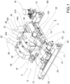
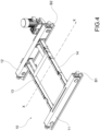
- the welding machine 1 comprises a carriage 10 which acts as a movable support base for the entire welding machine 1 and is adapted to slide along the advancement direction X to follow the movement of the longitudinal objects.
- the carriage 10 comprises two beams 11, 12, which are provided with wheels 17 adapted to slide the carriage 10 parallel to said advancement direction X along a track B1, B2 (only a segment of which being shown in figure 4 ).
- the two beams 11, 12 are transversely connected to each other by at least two connection beams 13 and 14 to form a framework on which the remaining part of the welding machine 1 rests.
- the carriage 10 is provided with motor means 16, kinematically connected to the wheels 17.
- the motor means comprise an electric gear motor with pinion-rack type coupling on two tracks B1 and B2.
- the carriage 10 can comprise an appendage 15 extending in a cantilevered manner outside said framework transversely to said advancement direction X for housing one or more components of the welding machine.
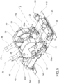
- the welding machine 1 comprises a first structure 20 which is supported by said carriage 10 and defines in a portion thereof a first passage seat 20a for the longitudinal metal products advancing along said transport line.
- the welding machine 1 also comprises a second structure 30 which is slidingly supported by said carriage 10, to slide parallel to the advancement direction X with respect to both the first structure 20 and the carriage 10 itself.
- Such a second structure 30 defines in a portion thereof a second passage seat 30a for the longitudinal metal products which advance along said transport line.
- Such a second passage seat 30a is aligned with said first passage seat 20a along said advancement direction X.
- the two structures 20 and 30 are connected to each other by two support beams 110 and 120, parallel to the advancement direction X.
- the two support beams 110 and 120 are fixedly anchored to the two beams 11, 12 of the carriage 10.
- the first structure 20 is fixedly anchored to the two support beams 110, 120, while the second structure 30 is slidingly connected to the two support beams 110, 120 by means of linear guides 111, 121 to slide parallel to the advancement direction X with respect to the first structure 20.
- the two structures 20 and 30 are connected by means of one or more actuators 131, 132 (e.g., hydraulic cylinders) adapted to impose a relative motion between the two structures parallel to the advancement axis X.
- actuators 131, 132 e.g., hydraulic cylinders
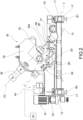
- the two structures 20 and 30 are mutually positioned so that there is a gap 2 therebetween.
- an inlet E and an outlet U for the longitudinal objects can be identified.
- the first structure 20 (fixed) is arranged close to the outlet U, while the second structure 30 (movable) is arranged close to the inlet E.
- the welding machine 1 further comprises:
- the first gripping means comprise two clamps 21, 22, which are mutually opposed with respect to the first passage seat 20a and between which the longitudinal metal object slides.
- a first clamp 21 lower clamp
- a second clamp 22 upper clamp
- the two clamps 21 and 22 are movable with respect to each other so as to be moved closer and farther apart so as to apply a reversible gripping action to the longitudinal object.
- the lower clamp 21 is fixed
- the upper clamp 22 is movable along an axis Z1 incident to the advancement axis X.
- the machine 1 is provided with a first linear actuator 26 (e.g., a hydraulic, pneumatic or electric cylinder), which is supported by the first structure 20 and is adapted to move the upper clamp 22 along said axis Z1.
- a first linear actuator 26 e.g., a hydraulic, pneumatic or electric cylinder
- the second gripping means also comprise two clamps 31, 32, which are mutually opposed with respect to the second passage seat 30a and between which the longitudinal metal object slides.
- a second clamp 31 lower clamp
- a second clamp 32 upper clamp
- the two clamps 31 and 32 are movable with respect to each other so as to be moved closer and farther apart so as to apply a reversible gripping action to the longitudinal object.
- the lower clamp 31 is fixed, while the upper clamp 32 is movable along an axis Z2 incident to the advancement axis X.
- the machine 1 is provided with a second linear actuator 36 (e.g., a hydrodynamic, pneumatic or electric cylinder), which is supported by the second structure 30 and is adapted to move the upper clamp 32 along said axis Z2.
- a second linear actuator 36 e.g., a hydrodynamic, pneumatic or electric cylinder
- said first structure 20 and said second structure 30 each extend longitudinally transversely to said advancement direction X between two respective longitudinally opposite support portions 23, 24 and 33, 34 at which each structure 20, 30 is connected to the carriage 10 by means of the aforesaid support beams 110 and 120.
- each structure also comprises a frame 25, 35 which is arranged between the respective support portions 23, 24 and 33, 34 and is configured to house the actuator 26, 36 of the respective gripping means 21, 22 and 31, 32.
- the welding machine can also comprise a first guide device 27 and a second guide device 37 which are arranged at the outlet and inlet of the welding machine, respectively, and are adapted to support and guide longitudinal metal objects through the welding machine 1 close to the first and second passage seats.
- first guide device 27 is supported by the first structure 20, while the second guide device 37 is supported by the second structure 30.
- each guide device 27, 37 defines lead-in and guide channel 28', 38', at the bottom of which at least one sliding roller 28",38" is positioned.
- both such guide devices are movable in height to vary the height position with which they support the longitudinal metal objects passing through the welding machine 1.
- each guide device 27, 37 is provided with respective movement means 29, 39, which in particular comprise a support guide 29',39' and an actuator 29", 39" (e.g., a pneumatic or hydraulic cylinder).
- the welding machine 1 further comprises a power group 40 which can be supplied with mains voltage and is provided with conductors 210; 221, 222, connected to the first gripping means 21, 22 and to the second gripping means 31, 32, respectively, for supplying electric current to the tail and head of two longitudinal objects.
- a power group 40 which can be supplied with mains voltage and is provided with conductors 210; 221, 222, connected to the first gripping means 21, 22 and to the second gripping means 31, 32, respectively, for supplying electric current to the tail and head of two longitudinal objects.
- the conductors can be rigid or flexible depending on whether they need to ensure an electrical connection with fixed or variable distance.
- Said power group 40 comprises:
- the rectifier 43 is integrated into the transformer 42.
- Two longitudinal metal objects M1 and M2 slide in sequence along the advancement axis X passing through the welding machine 1 at the two passage seats 20a and 30a.
- the two billets M1 and M2 slide supported by the two guide devices 27 and 37 (preferably arranged one at the inlet and one at the outlet of the machine) that in this step of the welding process are in a raised position to avoid friction between the billets and the lower clamps 21 and 31 of the first and second gripping means during their transit.
- the two billets continue to move until the tail T of the first billet M1 and the head H of the second billet M2 approach the centre of the gap 2 existing between the two structures 20 and 30.
- the head and tail of the billets are now in mutual contact.
- the upper clamp 22 of the first gripping means (supported by the first (fixed) structure 20) and the upper clamp 32 of the second gripping means (supported by the second movable structure 30) slide downward by means of the actuation of the respective linear actuators (hydraulic cylinders 26 and 36) along axis Z1 and axis Z2, respectively, until they block the two billets M1 and M2 by pressing them against the respective two lower clamps 21 and 31.
- the guide devices 27 and 37 are taken to the lowered position by the operation of the respective actuators 29" and 39" so that they do not interfere with the blocking of the billets between the upper and lower clamps.
- the carriage 10 supporting the whole machine is moved according to a rectilinear motion and parallel to the advancement axis X of the billets.
- the flashing step can now begin.
- the upsetting step can follow.
- the current flow is stopped when the preset melting level of the two billet faces is reached.
- the movable structure (the second structure 30), which is supported by the two linear guides positioned parallel to axis X, is fed by means of two hydraulic cylinders 131 and 132, which are fixed to the fixed structure (the first structure 20).
- the axial centres of the two hydraulic cylinders 131 and 132 are aligned on an axis Y which intersects the axis X and is situated in particular at about 65° from the perpendicular of axis X.
- the two cylinders are equidistant with respect to axis X.
- the movement of the movable structure 30 parallel to axis X and in the direction of the fixed structure 20 generates the pressure between the two faces of the billets, ensuring their joining.
- the two upper clamps 22 and 32 are returned to the initial position. Simultaneously, the two guide devices 27 and 37 are raised so as to support the billets from the previous contact with the two lower clamps 21 and 31.
- the movement means 16 of the carriage 10 reverse the travel direction and return the welding machine to a preset starting position, waiting for a new welding cycle.
- both hydraulic cylinders 131 and 132 simultaneously push the movable structure 30 back to the initial position thereof away from the fixed structure 20.
- the inverter 41 is a single-phase or poly-phase inverter with variable frequency, and said control unit 50 is programmed to operate said inverter 41 at frequencies above 700 Hz.
- Said at least one transformer 42 is sized to deliver a predetermined nominal power Pn at a predetermined nominal supply frequency fn.
- the predetermined nominal power Pn of the transformer 42 is lower than said predetermined operating power Pex and said nominal supply frequency fn is lower than 700 Hz.
- Said at least one transformer 42 is sized to deliver, at frequencies above 700 Hz, an actual power Pe equal to or greater than said predetermined operating power Pex.
- the predetermined nominal power Pn of transformer 42 is at least equal to said predetermined operating power Pex and said nominal supply frequency fn is above 700Hz.
- Said at least one transformer 42 is sized to deliver, at frequencies above 700 Hz, an actual power Pe greater than said predetermined operating power Pex.
- the welding machine 1 is thus capable of operating using transformers of small dimensions and low weight.
- the small size of the transformer results in a reduction of the spaces occupied by such a transformer and thus greater availability of free space to ensure the accessibility of operators to the welding machine.
- the welding machine 1 thus exhibits increased accessibility but without requiring significant increases in size.
- the welding machine for longitudinal metal objects also has no significantly higher construction costs than similar known machines.
- the transformer 42 (sized to deliver nominal power Pn less than Pex, at a nominal frequency fn less than 700 Hz) is forced to deliver power equal to or greater than Pex by operating it at a frequency above the nominal frequency fn.
- the electric power demand for welding is thus met by using a smaller transformer.
- such a mode has the disadvantage of increasing transformer losses, thus being inefficient.
- the transformer 42 (sized to deliver a nominal power Pn at least equal to Pex, at a nominal frequency fn greater than 700 Hz) can be operated at the nominal frequency fn by delivering the required power or be forced to deliver power greater than Pex by operating at a frequency greater than the nominal frequency fn.
- the electric power demand for welding is thus met by using a smaller transformer.
- Such a mode when it involves operating the transformer at the nominal frequency, also has the advantage of minimizing the transformer losses, thus being much more efficient.
- a transformer consists of a ring (core) made of ferromagnetic material (typically thin sheets of silicon steel) on which two windings are wound: the "primary,” consisting of n1 turns and the “secondary” consisting of n2 turns. Therefore, this is a double dipole. If the primary is supplied by a voltage generator v1 ("primary voltage"), so that a current i1 (“primary current”) flows through the primary, and the secondary is left open, so that the current i2 (“secondary current”) is zero, a magnetic induction field will be established in the ring (to which the "main” flux ⁇ shown in Figure 10 corresponds).
- the induction field lines also concatenate with the secondary winding, so that if i1 varies over time, by the Faraday's law (or electromagnetic induction law), a voltage v2 ("secondary voltage") will be induced at the secondary terminals. If the secondary is connected to a load (such as a resistor), current will thus circulate thereon. Therefore, by means of the transformer, is thus possible to transfer the electric power from the primary winding to the secondary one, without resorting to any electrical connection between the two windings; instead, the power transfer occurs through the magnetic field which is mainly present in the core of the transformer and is capable of exchanging energy with both circuits.
- a load such as a resistor
- the f.e.m. of a transformer at a given flux intensity increases with frequency.
- the transformers can be physically more compact because a given core can transfer more power without reaching saturation, and fewer turns are needed to obtain the same impedance.
- the problem of ensuring adequate accessibility to a welding machine is thus essentially solved by reducing the dimensions and weight of the transformer and not (or not necessarily) by changing the arrangement of the transformer itself on the welding machine.
- control unit 50 is programmed to cause said inverter 41 to operate at frequencies between 700 and 2000 Hz.
- control unit 50 is programmed to cause said inverter 41 to operate at frequencies between 900 and 1100 Hz and even more frequently at a frequency equal to about 1000 Hz.
- the size of the power group (transformer(s)) is so small that the placement thereof inside the welding machine is not limiting in terms of occupied space. This benefits the freedom of positioning of the transformer(s), increasing the accessibility and ease of maintenance of the machine.
- the power group (transformer(s)) can also be arranged inside the machine, as close as possible to the welding clamps, so as to minimize the length of the conductors connecting them to the clamps and thus reducing the electrical impedance generated by the conductors.
- the welding machine is powered by the distribution network or cell systems.
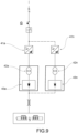
- the power group 40 can comprise a single transformer 42 (as shown in figures 6 , 7 and 8 ) or a plurality of transformers (42a, ... 42n) connected together in parallel (as shown in figure 9 ).
- Each transformer 42a,...42n is powered by a variable-frequency inverter 41a,...41n dedicated thereto and is electrically connected to the gripping means 21,22 and 31,32 preferably by means of a rectifier 43a,...43n dedicated thereto.
- Each of said transformers is sized to deliver a predetermined nominal power Pna,...Pnn at a predetermined nominal supply frequency fn.
- the transformers are sized according to two possible alternatives, similar to the case of a single transformer.
- the sum of the nominal powers Pna,... Pnn of said plurality of transformers is less than said predetermined operating power Pex to be generated during welding and said predetermined nominal supply frequency fn is less than 700Hz.
- Said plurality of transformers is sized to deliver as a whole at frequencies above 700HZ an actual power Pe equal to or greater than said predetermined operating power Pex.
- the sum of the nominal powers Pna,...Pnn of said plurality of transformers is at least equal to said predetermined operating power Pex to be generated during welding and said predetermined nominal supply frequency fn is greater than 700 Hz.
- Said plurality of transformers is sized to deliver as a whole at frequencies above said nominal supply frequency fn an actual power Pe greater than said predetermined operating power Pex.
- said predetermined operating power Pex has a value between 200 and 2000 kVA.
- each of said one or more transformers 42,42a, ...42n has a weight between 150 and 700kg.
- each of said one or more transformers 42,42a, ...42n has:
- the power group 40 can comprise a system adapted to provide a voltage boost during welding.
- such a system can be obtained by means of a device in the primary circuit of the transformer adapted to select a preset number of turns, referred to as active turns. Specifically, such a device must decrease the number of active turns of the primary circuit as compared to those of the secondary in order to have a voltage boost at the output of the transformer.
- the system adapted to provide the voltage boost can be achieved by means of a circuit element capable of varying the transformer primary circuit voltage.
- a circuit element capable of varying the transformer primary circuit voltage.
- such an element is capable of increasing the voltage of the inverter, which is upstream of the transformer, resulting in an increase in the voltage on the primary Vp.
- step-up converter is capable of increasing the voltage of the inverter, which is upstream of the transformer, resulting in an increase in the voltage on the primary Vp.
- the system provides a voltage boost between 1 and 1.8 times the nominal welding voltage.
- the system provides a voltage boost preferably equal to 1.4 times the nominal welding voltage value.
- the power factor on the power grid will have a value between 0.92 and 1.
- the problem of ensuring and adequate accessibility to a welding machine is substantially solved by reducing the dimensions and weight of the transformer and not (or not necessarily) by changing the arrangement of the transformer itself on the welding machine.
- the transformer or transformers has/have significantly small dimensions and low weights, they can be arranged in the welding machine substantially unconstrained.
- said at least one transformer 42 or said plurality of transformers 42a, ... 42n can be arranged behind the frames 25, 35 of said two structures 20, 30 with respect to said two passage seats 20a,30a.
- said at least one transformer 42 or said plurality of transformers 42a, ... 42n is arranged at the support portions 24, 34 of said structures 20,30.
- said at least one transformer 42 or said plurality of transformers 42a, ... 42n is arranged at the support portion 24 of the fixed structure 20.
- said at least one transformer 42 or said plurality of transformers 42a, ... 42n is arranged on the top of the frame 25, 35 of said first 20 or said second 30 structure. Preferably, they are arranged on the top of the frame 25 of the fixed structure 20.
- said at least one transformer 42 or said plurality of transformers 42a, ... 42n can be arranged in front of the frames 25, 35 of said two structures 20, 30 with respect to said two passage seats 20a,30a.
- said at least one transformer 42 or said plurality of transformers 42a, ... 42n is arranged at the support portions 23, 33 of said structures 20,30.
- said at least one transformer 42 or said plurality of transformers 42a, ... 42n is arranged at the support portion 23 of the fixed structure 20.
- said at least one transformer 42 or said plurality of transformers 42a, ... 42n can be arranged on an outer side of the frame 25, 35 of one of said two structures 20, 30, where outer side of a structure means the wall of the frame of a structure opposite to the wall facing the gap 2 between said two structures 20, 30.
- the carriage 10 comprises a framework which is delimited transversely to the advancement direction X by the two beams 11, 12.
- said framework is sized to support the two structures 20 and 30 within the size thereof in plan.
- the carriage can comprise an appendage 15 extending in a cantilevered manner outside said framework transversely to said advancement direction X, preferably behind the two frames 25, 35.
- Said at least one transformer 42 or said plurality of transformers 42a, ... 42n can be arranged on said appendage 15.
- the size of appendage 15 can also be minimized.
- the invention provides several advantages, some of which have already been described.
- the welding machine 1 for longitudinal metal objects according to the invention exhibits increased accessibility without requiring significant increases in size.
- the welding machine 1 for longitudinal metal objects according to the invention maintains adequate operating functionality.
- the welding machine 1 for longitudinal metal objects according to the invention is easy and convenient to manage.
- the welding machine 1 for longitudinal metal objects according to the invention has no significantly higher construction costs than similar known machines.
Landscapes
- Engineering & Computer Science (AREA)
- Mechanical Engineering (AREA)
- Physics & Mathematics (AREA)
- Optics & Photonics (AREA)
- Power Engineering (AREA)
- Arc Welding In General (AREA)
- Resistance Welding (AREA)
Applications Claiming Priority (1)
| Application Number | Priority Date | Filing Date | Title |
|---|---|---|---|
| IT202300024789 | 2023-11-22 |
Publications (1)
| Publication Number | Publication Date |
|---|---|
| EP4559613A1 true EP4559613A1 (de) | 2025-05-28 |
Family
ID=89898123
Family Applications (1)
| Application Number | Title | Priority Date | Filing Date |
|---|---|---|---|
| EP24213105.0A Pending EP4559613A1 (de) | 2023-11-22 | 2024-11-14 | Schweissmaschine zum längsschweissen von metallischen werkstücken, insbesondere knüppeln |
Country Status (5)
| Country | Link |
|---|---|
| US (1) | US20250162059A1 (de) |
| EP (1) | EP4559613A1 (de) |
| JP (1) | JP2025084718A (de) |
| KR (1) | KR20250076437A (de) |
| CN (1) | CN120023442A (de) |
Families Citing this family (1)
| Publication number | Priority date | Publication date | Assignee | Title |
|---|---|---|---|---|
| ES2980908T3 (es) * | 2020-02-03 | 2024-10-03 | Danieli Off Mecc | Máquina de soldar |
Citations (9)
| Publication number | Priority date | Publication date | Assignee | Title |
|---|---|---|---|---|
| JPH09267183A (ja) * | 1996-03-29 | 1997-10-14 | Kawasaki Steel Corp | フラッシュバット溶接機の制御装置 |
| US6107594A (en) * | 1997-04-16 | 2000-08-22 | Nkk Corporation | Flash butt welding device |
| JP2003033883A (ja) * | 2001-07-18 | 2003-02-04 | Nkk Corp | 大断面部材用フラッシュ溶接電源 |
| CN102522905A (zh) * | 2011-11-28 | 2012-06-27 | 镇江市黄墟锚链有限公司 | 链条电阻焊设备的中频直流电源及中频直流电阻焊方法 |
| CN108746961A (zh) * | 2018-04-27 | 2018-11-06 | 温岭市电焊设备厂 | 闪光中频逆变直流焊轨机 |
| EP3232453B1 (de) * | 2016-04-14 | 2019-06-12 | Robert Bosch Gmbh | Transformatoranordnung |
| EP3693981A1 (de) * | 2019-02-08 | 2020-08-12 | Robert Bosch GmbH | Bauteil und transformatoranordnung zum widerstandsschweissen |
| EP3812055A1 (de) * | 2019-10-24 | 2021-04-28 | Danieli & C. Officine Meccaniche S.p.A. | Schweissmaschine und entsprechendes verfahren |
| WO2021156738A1 (en) | 2020-02-03 | 2021-08-12 | Danieli & C. Officine Meccaniche S.P.A. | Welding machine |
-
2024
- 2024-11-14 EP EP24213105.0A patent/EP4559613A1/de active Pending
- 2024-11-21 US US18/954,820 patent/US20250162059A1/en active Pending
- 2024-11-21 JP JP2024202889A patent/JP2025084718A/ja active Pending
- 2024-11-22 CN CN202411678126.4A patent/CN120023442A/zh active Pending
- 2024-11-22 KR KR1020240167966A patent/KR20250076437A/ko active Pending
Patent Citations (9)
| Publication number | Priority date | Publication date | Assignee | Title |
|---|---|---|---|---|
| JPH09267183A (ja) * | 1996-03-29 | 1997-10-14 | Kawasaki Steel Corp | フラッシュバット溶接機の制御装置 |
| US6107594A (en) * | 1997-04-16 | 2000-08-22 | Nkk Corporation | Flash butt welding device |
| JP2003033883A (ja) * | 2001-07-18 | 2003-02-04 | Nkk Corp | 大断面部材用フラッシュ溶接電源 |
| CN102522905A (zh) * | 2011-11-28 | 2012-06-27 | 镇江市黄墟锚链有限公司 | 链条电阻焊设备的中频直流电源及中频直流电阻焊方法 |
| EP3232453B1 (de) * | 2016-04-14 | 2019-06-12 | Robert Bosch Gmbh | Transformatoranordnung |
| CN108746961A (zh) * | 2018-04-27 | 2018-11-06 | 温岭市电焊设备厂 | 闪光中频逆变直流焊轨机 |
| EP3693981A1 (de) * | 2019-02-08 | 2020-08-12 | Robert Bosch GmbH | Bauteil und transformatoranordnung zum widerstandsschweissen |
| EP3812055A1 (de) * | 2019-10-24 | 2021-04-28 | Danieli & C. Officine Meccaniche S.p.A. | Schweissmaschine und entsprechendes verfahren |
| WO2021156738A1 (en) | 2020-02-03 | 2021-08-12 | Danieli & C. Officine Meccaniche S.P.A. | Welding machine |
Also Published As
| Publication number | Publication date |
|---|---|
| KR20250076437A (ko) | 2025-05-29 |
| CN120023442A (zh) | 2025-05-23 |
| US20250162059A1 (en) | 2025-05-22 |
| JP2025084718A (ja) | 2025-06-03 |
Similar Documents
| Publication | Publication Date | Title |
|---|---|---|
| RU2709494C1 (ru) | Компактная линия гомогенизации непрерывным отжигом | |
| EP4559613A1 (de) | Schweissmaschine zum längsschweissen von metallischen werkstücken, insbesondere knüppeln | |
| US6248984B1 (en) | Method and apparatus for joining metal pieces | |
| CS275610B6 (en) | Device for induction heating | |
| KR102082712B1 (ko) | 가동 가압 부재를 갖는 스폿 용접 전극 및 그것을 사용한 스폿 용접 방법 | |
| EP3714074B1 (de) | Heizvorrichtung und entsprechende vorrichtung und verfahren | |
| US20150257207A1 (en) | Transverse flux strip heating with dc edge saturation | |
| CN104673988A (zh) | 一种感应加热退火机床 | |
| AU734645B2 (en) | System, apparatus, and method for heating metal products in an oscillating induction furnace | |
| EP0495993B2 (de) | Verfahren und vorrichtung zum verbinden von knüppeln | |
| EP2886237B1 (de) | Schweissvorrichtung und -verfahren zum herstellen eines widerstandsgeschweissten rohres | |
| IT201700020203A1 (it) | Apparato di riscaldamento per prodotti metallici | |
| KR920000514B1 (ko) | 전자 부양 주조 장치 | |
| CN215587494U (zh) | 一种热轧不锈钢退火酸洗线 | |
| SE506294C2 (sv) | Anordning för sammanfogning av två av plåt framställda arbetsstycken | |
| CN107020453A (zh) | 一种激光‑电弧‑磁场复合焊接的励磁移动平台 | |
| KR102888852B1 (ko) | 횡류 유도에 의한 제품 가열 장치 | |
| JP2001006862A (ja) | 電磁誘導加熱装置 | |
| WO1997048515A1 (en) | Method and installation for butt welding two sheet sections, and coil for use therewith | |
| CN108115252A (zh) | 自动焊接机器人装置 | |
| JP4533231B2 (ja) | 鋼帯の製造設備及び溶融めっき設備 | |
| JPH07144203A (ja) | 鋼片の接合方法 | |
| JP2014136237A (ja) | 溶接方法と溶接装置 | |
| JPH07201461A (ja) | 薄板誘導加熱装置 |
Legal Events
| Date | Code | Title | Description |
|---|---|---|---|
| PUAI | Public reference made under article 153(3) epc to a published international application that has entered the european phase |
Free format text: ORIGINAL CODE: 0009012 |
|
| STAA | Information on the status of an ep patent application or granted ep patent |
Free format text: STATUS: THE APPLICATION HAS BEEN PUBLISHED |
|
| AK | Designated contracting states |
Kind code of ref document: A1 Designated state(s): AL AT BE BG CH CY CZ DE DK EE ES FI FR GB GR HR HU IE IS IT LI LT LU LV MC ME MK MT NL NO PL PT RO RS SE SI SK SM TR |
|
| STAA | Information on the status of an ep patent application or granted ep patent |
Free format text: STATUS: REQUEST FOR EXAMINATION WAS MADE |