EP4099876B1 - Beverage preparation machine with capsule recognition - Google Patents
Beverage preparation machine with capsule recognition Download PDFInfo
- Publication number
- EP4099876B1 EP4099876B1 EP21702285.4A EP21702285A EP4099876B1 EP 4099876 B1 EP4099876 B1 EP 4099876B1 EP 21702285 A EP21702285 A EP 21702285A EP 4099876 B1 EP4099876 B1 EP 4099876B1
- Authority
- EP
- European Patent Office
- Prior art keywords
- capsule
- machine
- colour
- type
- sample
- Prior art date
- Legal status (The legal status is an assumption and is not a legal conclusion. Google has not performed a legal analysis and makes no representation as to the accuracy of the status listed.)
- Active
Links
- 239000002775 capsule Substances 0.000 title claims description 501
- 235000013361 beverage Nutrition 0.000 title claims description 87
- 238000002360 preparation method Methods 0.000 title description 26
- 238000000605 extraction Methods 0.000 claims description 108
- 239000013598 vector Substances 0.000 claims description 87
- 239000007788 liquid Substances 0.000 claims description 82
- 239000004615 ingredient Substances 0.000 claims description 37
- 235000016213 coffee Nutrition 0.000 claims description 12
- 235000013353 coffee beverage Nutrition 0.000 claims description 12
- 238000000034 method Methods 0.000 claims description 12
- 239000003086 colorant Substances 0.000 claims description 11
- 235000013616 tea Nutrition 0.000 claims description 8
- 239000008267 milk Substances 0.000 claims description 7
- 235000013336 milk Nutrition 0.000 claims description 7
- 210000004080 milk Anatomy 0.000 claims description 7
- 235000014347 soups Nutrition 0.000 claims description 6
- 235000008452 baby food Nutrition 0.000 claims description 5
- 235000019219 chocolate Nutrition 0.000 claims description 5
- 235000020278 hot chocolate Nutrition 0.000 claims description 3
- 241001122767 Theaceae Species 0.000 claims 1
- 239000000463 material Substances 0.000 description 15
- 240000007154 Coffea arabica Species 0.000 description 11
- 235000013350 formula milk Nutrition 0.000 description 8
- XLYOFNOQVPJJNP-UHFFFAOYSA-N water Substances O XLYOFNOQVPJJNP-UHFFFAOYSA-N 0.000 description 8
- 244000269722 Thea sinensis Species 0.000 description 6
- 238000003780 insertion Methods 0.000 description 6
- 230000037431 insertion Effects 0.000 description 6
- 239000002699 waste material Substances 0.000 description 6
- 244000299461 Theobroma cacao Species 0.000 description 5
- 101150068479 chrb gene Proteins 0.000 description 5
- 238000013500 data storage Methods 0.000 description 4
- 230000003750 conditioning effect Effects 0.000 description 3
- 230000010354 integration Effects 0.000 description 3
- 230000005055 memory storage Effects 0.000 description 3
- 238000004806 packaging method and process Methods 0.000 description 3
- 229920003023 plastic Polymers 0.000 description 3
- 239000004411 aluminium Substances 0.000 description 2
- 229910052782 aluminium Inorganic materials 0.000 description 2
- XAGFODPZIPBFFR-UHFFFAOYSA-N aluminium Chemical compound [Al] XAGFODPZIPBFFR-UHFFFAOYSA-N 0.000 description 2
- RYYVLZVUVIJVGH-UHFFFAOYSA-N caffeine Chemical compound CN1C(=O)N(C)C(=O)C2=C1N=CN2C RYYVLZVUVIJVGH-UHFFFAOYSA-N 0.000 description 2
- 235000020291 caffè lungo Nutrition 0.000 description 2
- 238000004364 calculation method Methods 0.000 description 2
- 238000004140 cleaning Methods 0.000 description 2
- 238000012937 correction Methods 0.000 description 2
- 238000001514 detection method Methods 0.000 description 2
- 235000015114 espresso Nutrition 0.000 description 2
- 239000012530 fluid Substances 0.000 description 2
- 230000006870 function Effects 0.000 description 2
- 230000003100 immobilizing effect Effects 0.000 description 2
- 230000001939 inductive effect Effects 0.000 description 2
- 238000001802 infusion Methods 0.000 description 2
- 230000003287 optical effect Effects 0.000 description 2
- 230000002093 peripheral effect Effects 0.000 description 2
- 239000000843 powder Substances 0.000 description 2
- 230000008569 process Effects 0.000 description 2
- 238000012546 transfer Methods 0.000 description 2
- 206010001488 Aggression Diseases 0.000 description 1
- LPHGQDQBBGAPDZ-UHFFFAOYSA-N Isocaffeine Natural products CN1C(=O)N(C)C(=O)C2=C1N(C)C=N2 LPHGQDQBBGAPDZ-UHFFFAOYSA-N 0.000 description 1
- 235000005764 Theobroma cacao ssp. cacao Nutrition 0.000 description 1
- 235000005767 Theobroma cacao ssp. sphaerocarpum Nutrition 0.000 description 1
- 230000004913 activation Effects 0.000 description 1
- 230000016571 aggressive behavior Effects 0.000 description 1
- 235000001046 cacaotero Nutrition 0.000 description 1
- 229960001948 caffeine Drugs 0.000 description 1
- VJEONQKOZGKCAK-UHFFFAOYSA-N caffeine Natural products CN1C(=O)N(C)C(=O)C2=C1C=CN2C VJEONQKOZGKCAK-UHFFFAOYSA-N 0.000 description 1
- 235000015109 caffè americano Nutrition 0.000 description 1
- 235000015115 caffè latte Nutrition 0.000 description 1
- 235000015116 cappuccino Nutrition 0.000 description 1
- 235000020965 cold beverage Nutrition 0.000 description 1
- 230000000295 complement effect Effects 0.000 description 1
- 239000012141 concentrate Substances 0.000 description 1
- 230000006378 damage Effects 0.000 description 1
- 239000003085 diluting agent Substances 0.000 description 1
- 230000007613 environmental effect Effects 0.000 description 1
- 238000002474 experimental method Methods 0.000 description 1
- 239000000796 flavoring agent Substances 0.000 description 1
- 235000019634 flavors Nutrition 0.000 description 1
- 235000021554 flavoured beverage Nutrition 0.000 description 1
- 238000010438 heat treatment Methods 0.000 description 1
- 238000010348 incorporation Methods 0.000 description 1
- 230000000977 initiatory effect Effects 0.000 description 1
- 230000003993 interaction Effects 0.000 description 1
- 235000020307 latte macchiato Nutrition 0.000 description 1
- 238000004519 manufacturing process Methods 0.000 description 1
- 238000005259 measurement Methods 0.000 description 1
- 230000007246 mechanism Effects 0.000 description 1
- 229910052751 metal Inorganic materials 0.000 description 1
- 239000002184 metal Substances 0.000 description 1
- 238000002156 mixing Methods 0.000 description 1
- 230000003071 parasitic effect Effects 0.000 description 1
- 230000002572 peristaltic effect Effects 0.000 description 1
- 238000012545 processing Methods 0.000 description 1
- 235000020288 ristretto Nutrition 0.000 description 1
- 238000001228 spectrum Methods 0.000 description 1
- 239000000126 substance Substances 0.000 description 1
Images


Classifications
-
- A—HUMAN NECESSITIES
- A47—FURNITURE; DOMESTIC ARTICLES OR APPLIANCES; COFFEE MILLS; SPICE MILLS; SUCTION CLEANERS IN GENERAL
- A47J—KITCHEN EQUIPMENT; COFFEE MILLS; SPICE MILLS; APPARATUS FOR MAKING BEVERAGES
- A47J31/00—Apparatus for making beverages
- A47J31/44—Parts or details or accessories of beverage-making apparatus
- A47J31/4492—Means to read code provided on ingredient pod or cartridge
Definitions
- the field of the invention pertains to beverage preparation machines using capsules of an ingredient of the beverage to be prepared.
- the field of the invention pertains in particular to beverage preparation machines using capsules and configured to automatically recognize a type of a capsule inserted in the machine in order for example to adapt the beverage preparation parameters to the recognized capsule type.
- a "beverage” is meant to include any human-consumable liquid substance, such as tea, coffee, hot or cold chocolate, milk, soup, baby food, etc.
- a "capsule” is meant to include any pre-portioned beverage ingredient, such as a flavouring ingredient, within an enclosing packaging of any material, in particular an airtight packaging, e.g. plastic, aluminium, recyclable and/or biodegradable packagings, and of any shape and structure, including soft pods or rigid cartridges containing the ingredient.
- the capsule may contain an amount of ingredient for preparing a single beverage portion or a plurality of beverage portions.
- Certain beverage preparation machines use capsules containing ingredients to be extracted or to be dissolved and/or ingredients that are stored and dosed automatically in the machine or else are added at the time of preparation of the drink.
- Some beverage machines possess filling means that include a pump for liquid, usually water, which pumps the liquid from a source of water that is cold or indeed heated through heating means, e.g. a thermoblock or the like.
- Brewing devices have been developed to facilitate insertion of a "fresh" capsule and removal of the capsule upon use.
- the brewing devices comprise two parts relatively movable from a configuration for inserting/removing a capsule to a configuration for brewing the ingredient in the capsule.
- the actuation of the movable part of the brewing device may be manual as disclosed in WO 2009/043630 , WO 01/15581 , WO 02/43541 , WO 2010/015427 , WO 2010/128109 , WO 2011/144719 and WO 2012/032019 .
- the actuation of the movable part of the brewing device may be motorized.
- a system is for example disclosed in EP 1 767 129 .
- the user does not have to provide any manual effort to open or close the brewing device.
- the brewing device has a capsule insertion passage provided with a safety door assembled to the movable part of the brewing device via a switch for detecting an undesired presence of a finger in the passage during closure and prevent injuries by squeezing.
- Alternative covers for a capsule insertion passage are disclosed WO 2012/093107 and WO 2013/127906 .
- Different motorization systems are disclosed in WO 2012/025258 , WO 2012/025259 and WO 2013/127476 .
- WO 2019/154527 A1 discloses a beverage preparation machine, comprising an extraction unit for extracting a beverage ingredient capsule to form said beverage, e.g. a unit having a first part and a second part that are relatively movable between a distant position for inserting and/or removing a capsule and a closed position, such as a closed position in which the first and second parts delimit an extraction chamber, for securing and extracting such capsule, optionally at least one of the parts has a capsule opener e.g.
- one or more capsule piercers and/or at least one of the parts has an opening for an inflow of liquid to be mixed with an ingredient contained in such capsule; a control unit for controlling the extraction unit to extract such capsule, such as a control unit powered by the mains e.g. via an electric cord; an outlet for dispensing the beverage formed by extracting such capsule to a user-receptacle, such as a cup or a mug, located in a receptacle placing area, such as on a receptacle support e.g. an external placement support on which such machine is located or a machine support e.g.
- a capsule recognition module for recognizing a type of a capsule inserted in the machine, the capsule recognition module comprising a sensor for sensing a property of at least part of such capsule and determining a sample value representative of the property of such capsule; wherein the capsule recognition module is configured to compare the sample value to a plurality of reference values, wherein each reference value corresponds to a type of capsule, by, for each reference value of the plurality of reference values, computing a score representative of a probability of a match between the sample value and the reference value; wherein the capsule recognition module is configured to, if a determination of the capsule type can be made with sufficient certainty, for example if a single reference value results in a score indicating a probability of match higher than a predefined threshold, determine that such capsule is of the type corresponding to the respective reference value.
- the invention relates to a machine for preparing a beverage.
- the beverage preparation machine can be an in-home or out of home machine.
- the machine may be for the preparation of coffee, tea, chocolate, cacao, milk, soup, baby food, etc.
- the beverage preparation typically includes the mixing of a plurality of beverage ingredients, e.g. water and milk powder, and/or the infusion of a beverage ingredient, such as an infusion of ground coffee or tea with water.
- a beverage ingredient such as an infusion of ground coffee or tea with water.
- One or more of such ingredients may be supplied in loose and/or agglomerate powder form and/or in liquid form, in particular in a concentrate form.
- a carrier or diluents liquid, e.g. water may be mixed with such ingredient to form the beverage.
- a predetermined amount of beverage is formed and dispensed on user-request, which corresponds to a portion (e.g. a serving).
- the volume of such portion may be in the range of 25 to 200 ml and even up to 300 or 400 ml, e.g.
- a coffee machine may be configured for dispensing espressos, e.g. an adjustable volume of 20 to 60 ml per portion, and/or for dispensing lungos, e.g. a volume in the range of 70 to 150 ml per portion.
- the machine of the invention has a unit for extracting a beverage ingredient capsule to form the beverage.
- the unit has a first part and a second part that are relatively movable between a distant position for inserting and/or removing a capsule and a closed position for securing and extracting such capsule. In the closed position the first and second parts typically delimit an extraction chamber.
- the capsule can comprise a capsule body, e.g. a generally straight or tapered body.
- the capsule can have a circular peripheral annulus flange, e.g. a flexible or rigid flange, extending from a peripheral part, e.g. an edge or face, of the capsule body.
- the capsule may contain a flavoring ingredient for preparing tea, coffee, hot chocolate, cold chocolate, milk, soup or baby food.
- At least one part of the first and second parts may delimit a cavity for receiving the ingredient e.g. within a capsule, such as a tapered cavity, e.g. a conical or pyramidal cavity, or a straight cavity, e.g. a cylindrical or trapezoidal cavity.
- a cavity for receiving the ingredient e.g. within a capsule, such as a tapered cavity, e.g. a conical or pyramidal cavity, or a straight cavity, e.g. a cylindrical or trapezoidal cavity.
- a cavity may extend along an axis that is generally collinear with a direction of relative movement of the first and second parts.
- the extraction chamber is then delimited on one side by such cavity.
- first and second parts may be delimited by another cavity or include an extraction plate, such as a plate provided with piercing elements for opening a flow-through face of the capsule or a non-intrusive plate for cooperating with a pre-opened or a self-opening flow-through face of the capsule.
- an extraction plate such as a plate provided with piercing elements for opening a flow-through face of the capsule or a non-intrusive plate for cooperating with a pre-opened or a self-opening flow-through face of the capsule.
- At least one of these parts can have a capsule opener e.g. one or more capsule piercers.
- the capsule can also include a self-opening mechanism.
- Self-opening capsules are for instance disclosed in CH 605 293 and WO 03/059778 .
- the first and second parts may include a capsule opener such as blades and/or a tearing tool, e.g. a plate with a tearing profile, for instance as known from Nespresso TM machines or as disclosed in EP 0 512 470 , EP 2 068 684 and WO 2014/076041 and the references cited therein.
- a capsule opener such as blades and/or a tearing tool, e.g. a plate with a tearing profile, for instance as known from Nespresso TM machines or as disclosed in EP 0 512 470 , EP 2 068 684 and WO 2014/076041 and the references cited therein.
- At least one of the parts may have an opening for an inflow of liquid to be mixed with an ingredient contained in such capsule.
- the machine includes a control unit for controlling the extracting unit to extract such capsule.
- the control unit can be powered by the mains e.g. via an electric cord.
- the machine has an outlet for dispensing the beverage formed by extracting such capsule to a user-receptacle, such as a cup or a mug, located in a receptacle placing area.
- a user-receptacle such as a cup or a mug
- a flavoured beverage may be prepared by circulating (by means of a liquid driver, e.g. a pump) a carrier liquid, such as water, into the capsule to flavour the liquid by exposure to a flavouring ingredient held in the capsule, e.g. along an extraction direction that may be generally parallel to the direction of relative movement of the first and second parts or to a longitudinal or central direction of the extraction.
- a liquid driver e.g. a pump
- a carrier liquid such as water
- the user receptacle can be placed on a receptacle support to collect the beverage.
- the receptacle support can be formed by an external placement support on which such machine is located.
- the receptacle support may be formed by a support comprised by the machine, e.g. a movable or removable machine support.
- the receptacle placing area can be associated with a machine recipient support for supporting such user-recipient under the outlet.
- the support can be: associated with a drip tray e.g. a drip tray supporting the support; and/or movable relative to the housing vertically under the outlet and/or away from under the outlet for enabling a placement of user-recipients of different heights under the outlet.
- EP 0 549 887 EP 1 440 639 , EP 1 731 065 , EP 1 867 260 , US 5,161,455 , US 5,353,692 , WO 2009/074557 , WO 2009/074559 , WO 2009/135869 , WO 2011/154492 , WO 2012/007313 , WO 2013/186339 , WO 2016/096705 , WO 2016/096706 and WO 2016/096707 .
- the outlet can be fixed to or formed by or mounted to or mounted in:
- the machine is provided with a machine head as disclosed in WO 2017/037212 and in WO 2017/037215 .
- waste receptacles for carrying out the present invention are disclosed in EP 1867260 , WO 2009/074559 , WO 2009/135869 , WO 2010/128109 , WO 2011/086087 , WO 2011/086088 , PCT/EP2017/050237 and WO 2017/037212 .
- the directing fluid guide can be entirely confined in the main body and/or the machine head.
- the extraction unit can include a capsule feeder for feeding a capsule to the extraction chamber, the feeder having a capsule dispenser with a release configuration for releasing such capsule from the feeder towards the extraction chamber and a retain configuration for retaining such capsule away from the extraction chamber.
- the capsule dispenser can be formed by a mechanical and/or magnetic capsule gate such as a capsule holder e.g. having a shape complementary to and matching at least part of an outer shape of such capsule.
- the capsule holder may have a capsule gate that is movable, such as pivotable and/or translatable, between a position obstructing a transfer towards the extraction chamber and a position clearing the transfer towards the extraction chamber.
- the capsule holder may have an actuator for passing from the retain configuration to the release configuration and vice versa, such as an actuator controlled by the control unit.
- the capsule dispenser may be passed from the release configuration to the retain configuration so that access towards the extraction chamber is only provided when needed to release a capsule.
- the capsule feeder may include a passage for guiding such capsule to the extraction chamber into a predetermined capsule orientation for its entry into the extraction chamber such as a passage associated with capsule immobilizer for immobilizing such capsule between the first and second parts in their distant position prior to relatively moving them into their closed position.
- the interaction between the first and second parts (and optionally the capsule guiding passage) and an ingredient capsule may be of the type disclosed in WO 2005/004683 , WO 2007/135135 , WO 2007/135136 , WO 2008/037642 and WO 2013/026856 .
- the control unit may control the capsule dispenser to release such capsule from the feeder when the first and second parts are in the distant position or moving towards the distant position, for an entry of such capsule into the extraction chamber when the first and second parts are brought back into their closed position.
- the control unit may control the capsule dispenser to retain such capsule at the feeder and away from the extraction chamber when the first and second parts are:
- the capsule feeder may include or be associated with a capsule sensor connected to the control unit, the control unit being configured to bring or maintain the capsule dispenser in its retain configuration when the capsule sensor senses no such capsule on or at the capsule dispenser.
- capsule sensors are for example disclosed in WO 2012/123440 , WO 2014/147128 , WO 2015/173285 , WO 2015/173289 , WO 2015/173292 , WO 2016/005352 and WO 2016/005417 .
- the control unit can be configured to control the actuator so that the first and second parts are moved by the actuator: from the closed position into the distant position and from the distant position into the closed position after a predetermined period of time starting for example from a beverage preparation triggering event such as for example capsule detection, capsule recognition, user actuation of the machine's user interface, etc., or a combination thereof, for instance a predetermined period of time in the range of 3 to 15 sec, such as 5 to 12 sec, e.g. 7 to 10 sec.
- a beverage preparation triggering event such as for example capsule detection, capsule recognition, user actuation of the machine's user interface, etc., or a combination thereof, for instance a predetermined period of time in the range of 3 to 15 sec, such as 5 to 12 sec, e.g. 7 to 10 sec.
- Examples of such parts that are relatively moved by an actuator e.g. a motor are disclosed in EP 1767129 , WO 2012/025258 , WO 2012/025259 , WO 2013/127476 and WO 2014/056641 .
- first part and the second part are relatively movable generally along a straight axis by the actuator from the closed to the distant positions and/or vice versa.
- the machine may include a liquid supplier for supplying liquid, e.g. water, into the extraction chamber, the liquid supplier being connected to and controlled by the control unit to supply such liquid into the extraction chamber and to interrupt such supply, automatically and/or manually via a user-interface connected to the control unit and/or when a removal of such receptacle is detected by the detecting arrangement.
- the liquid supplier includes one or more of: a source of said liquid, such as a liquid tank or a liquid connector for connection to an external liquid provider; one or more liquid tubes for guiding such liquid to the extraction chamber; a liquid driver, such as a pump e.g.
- a solenoid pump reciprocating piston pump
- a peristaltic pump for driving such liquid into extraction chamber
- a thermal conditioner e.g. a heater and/or a cooler, such as an inline thermal conditioner, e.g. an inline flow conditioner, for thermally conditioning such liquid.
- liquid sources e.g. tanks or connectors
- suitable liquid sources e.g. tanks or connectors
- the thermal conditioner may be a boiler or a thermoblock or an on demand heater (ODH), for instance an ODH type disclosed in EP 1 253 844 , EP 1 380 243 and EP 1 809 151 .
- ODH on demand heater
- the control unit may be configured to control the liquid supplier to supply automatically the liquid into the extraction chamber when:
- the control unit can be configured to control the liquid supplier not to supply automatically the liquid into the extraction chamber when the first and second parts have reached their closed position without any (for instance detected or recognised) capsule housed in the extraction chamber.
- the control unit is configured to control the liquid supplier to supply the liquid into the extraction chamber upon sensing a corresponding manual user-input on a user-interface connected to the control unit.
- the control unit may have an end-of-extraction management program which is run automatically when the liquid supply is interrupted (e.g. when a predetermined extraction process is over or is detected as faulty) to:
- the parts may remain into their distant position for a predetermined period of time, such as a period of time in the range of 1 to 6 sec. e.g. 2 to 4 sec, for allowing an insertion of a new capsule inbetween the first and second parts prior to relatively moving them into their closed position with the new capsule housed in the extraction chamber for an extraction of the new capsule.
- a predetermined period of time such as a period of time in the range of 1 to 6 sec. e.g. 2 to 4 sec, for allowing an insertion of a new capsule inbetween the first and second parts prior to relatively moving them into their closed position with the new capsule housed in the extraction chamber for an extraction of the new capsule.
- a user can request the dispensing of two (or more) portions of beverages (e.g. a double expresso) into the same user-recipient.
- the machine comprises:
- Selecting at least two reference values, i.e. at least two corresponding types of capsules, as a result of the capsule recognition process if no determination can be made with sufficient certainty allows avoiding extracting a capsule with inappropriate extraction parameters following of an error in the recognition process.
- Selecting at least two reference values having the highest probability of matching the sample value i.e. selecting at least two types having the highest probability of corresponding to the type of the recognised capsule, allows for example presenting such at least two types to a user that may then select manually the type that actually correspond to the type of the capsule.
- the capsule recognition module is configured to select three reference values out of the plurality of reference values, the three reference values being the three reference values from the plurality of reference values that resulted in the three scores indicating the highest probability of match with the sample value.
- the machine further comprises a user interface for displaying information to a user of the machine and receiving inputs from a user of the machine, wherein the machine is configured to display on the user interface information about the at least two types of capsule corresponding to the at least two selected reference values.
- the user interface is preferably configured to allow a user of said machine selecting one of the at least two types of capsule.
- the machine is preferably configured to control the extraction unit to extract such capsule using extraction parameters specifically adapted to a type of capsule selected by a user.
- the capsule recognition module is a colour recognition module
- the sensor is a colour sensor
- the sample value is a sample colour vector characterizing a sample colour
- the reference values are reference colour vectors each characterizing a reference colour, each reference colour corresponding to a type of capsule.
- the colour recognition module is for example configured to compare the sample colour to each reference colour of the plurality of reference colours by:
- the colour recognition module is for example configured to compute the sample chromaticity vector from the sample colour vector.
- the sample colour vector and the reference colour vector are preferably three-dimensional RGB vectors.
- the colour recognition module is for example configured to compute the score by computing a luminosity level of the sample colour and weighting the colour distance and the chromaticity distance by respective balance factors determined on the basis of the luminosity level.
- the machine preferably comprises a capsule recognition position.
- the machine further comprises a capsule detector for detecting the presence of a capsule located on or approaching a capsule feeder of the machine and triggering capsule recognition by the capsule recognition module.
- the invention relates to a combination of such a machine and a capsule, e.g. such capsule being in the machine's extraction chamber or such capsule being handled by a capsule feeder of the machine.
- the invention relates to a method of preparing and dispensing a beverage from a capsule in such a machine, the method comprising:
- the invention relates to a use of a capsule for such a machine, forming such a combination or carrying out such a method, whereby a type of the capsule is recognised by:
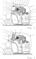
- Figs 1 to 8 illustrate an exemplary embodiment of a beverage machine 1 according to the invention for preparing and dispensing a beverage 2, such as tea, coffee, hot chocolate, cold chocolate, milk, soup or baby food.
- the ingredient may be supplied in the form of an ingredient capsule 3, e.g. of the type described above under the header "Field of the Invention".
- Figs 1 to 8 illustrates a beverage preparation sequence in machine 1 from the supply of an ingredient capsule 3 to the removal of capsule 3 upon beverage preparation.
- Machine 1 includes an extraction unit 10 for extracting beverage ingredient capsule 3 to form beverage 2.
- Extraction unit 10 for example has a first part 11 and a second part 12 that are relatively movable between a distant position for inserting and/or removing capsule 3 and a closed position, such as a closed position in which first and second parts 11,12 delimit an extraction chamber 100, for securing and extracting such capsule 3.
- at least one of parts 11,12 has a capsule opener e.g. one or more capsule piercers and/or at least one of said parts 11,12 has an opening for an inflow of liquid to be mixed with an ingredient contained in such capsule 3.
- Machine 1 includes a control unit 40, schematically illustrated in Figs. 2-8 , for controlling extraction unit 10 to extract capsule 3.
- Control unit 40 may be powered by the mains, e.g. via an electric cord 45, or by a DC source, e.g. battery such as a car battery or portable battery or machine battery.
- Machine 1 has an outlet 20 for dispensing beverage 2 formed by extracting such capsule 3 to a user-receptacle 4, such as a cup or a mug, located in a receptacle placing area to collect beverage 2.
- a user-receptacle 4 such as a cup or a mug
- Such area may be on a receptacle support 5,6 e.g. an external placement support 5 on which such machine 1 is located or a machine support 6 e.g. a movable or removable machine support 6, e.g. a machine support 6 that is located on or above an external placement support 5.
- outlet 20 is for example fixed to or formed by or mounted to or mounted in a machine head 21 that has a deployed position in which outlet 20 is located above the receptacle placing area and a collapsed position in which outlet 20 is retracted within an external machine main housing 14.
- Machine head 21 may be driven inwards into and outwards out of the housing 14 by at least one of the first and second parts 11,12 or by an actuator controlled by the control unit.
- Outlet 20 can be fixed to or formed by or mounted to or mounted in a movable beverage guide 22 that has a beverage dispensing configuration illustrated for example on Fig. 6 to dispense beverage 2 to the receptacle placing area and a beverage stop configuration visible for example in Fig. 2 to prevent dispensing of beverage to the receptacle placing area, e.g. by draining residual beverage from guide 22 over a guide edge 23 to a waste receptacle 60.
- Guide 22 can be driven between the dispensing configuration and the stop configuration by at least one of first and second parts 11,12 or by a (or the above) machine head 21 or by an actuator controlled by the control unit.
- Extraction unit 10 includes an actuator 13 configured to relatively move first and second parts 11,12 between their relatively distant and closed positions.
- Actuator 13 is connected to control unit 40 and controlled thereby to relatively move first and second parts 11,12.
- Control unit 40 is connected to an input device for initiating and/or controlling the extraction unit 10.
- the input device comprises for example a user interface 41 and a capsule recognition module 8 to recognise a type of a capsule 3 ready to be inserted into the extraction unit 10.
- the input device optionally further comprises a capsule sensor for sensing the presence of a capsule 3 located in and/or approaching the extraction unit 10.
- Extraction unit 10 may include a capsule feeder 15 for feeding a capsule 3 to extraction chamber 100.
- the capsule feeder 15 can have a capsule dispenser 151 with a release configuration for releasing the capsule 3 from the capsule feeder 15 towards the extraction chamber 100 and a retain configuration for retaining the capsule 3 away from the extraction chamber 100.
- the capsule feeder 15 can include a mechanical and/or magnetic capsule gate such as a capsule holder 151 e.g. matching at least part of an outer shape of the capsule 3.
- the capsule feeder 15 can have a passage 152 ( Fig. 4 ) for guiding the capsule 3 to the extraction chamber 100 into a predetermined capsule orientation for its entry into the extraction chamber 100, such as a passage 152 associated with a capsule immobilizer for immobilizing the capsule 3 between the first and second parts 11,12 in their distant position ( Fig. 5 ) prior to moving them relatively to each other into their closed position ( Fig. 6 ).
- a passage 152 for guiding the capsule 3 to the extraction chamber 100 into a predetermined capsule orientation for its entry into the extraction chamber 100, such as a passage 152 associated with a capsule immobilizer for immobilizing the capsule 3 between the first and second parts 11,12 in their distant position ( Fig. 5 ) prior to moving them relatively to each other into their closed position ( Fig. 6 ).
- the control unit 40 may control the capsule dispenser 151 to release the capsule 3 from the feeder 15 when the first and second parts 11,12 are in the distant position ( Fig. 4 ) or when they are moving towards the distant position, for an entry of the capsule 3 into the extraction chamber 100 when the first and second parts 11,12 are brought back into their closed position ( Fig. 6 ).
- Control unit 40 may control capsule dispenser 151 to retain the capsule 3 at the feeder 15 and away from the extraction chamber 100 when the first and second parts 11,12 are: in the closed position or moving thereto ( Fig. 2 ); or in the distant position and about to move to the closed position so as to leave insufficient time for the capsule 3, if it were released from the dispenser 151, to be received into the extraction chamber 100 prior to the first and second parts 11,12 reaching the closed position.
- the capsule feeder 15 may include or be associated with a capsule sensor connected to the control unit 40, which is for example configured to bring or maintain the capsule dispenser 151 in its retain configuration when the capsule sensor senses no capsule 3 on or at the capsule dispenser 151 ( Fig. 7 ).
- the control unit 40 may be configured to control the actuator 13 so that the first and second parts 11,12 are moved by the actuator 13 from the distant position into the closed position after a predetermined period of time has lapsed starting from a beverage preparation triggering event such as for example capsule detection, capsule recognition, user actuation of the machine's user interface, or reaching the distant position, or a combination thereof ( Figs 2 to 6 );
- a beverage preparation triggering event such as for example capsule detection, capsule recognition, user actuation of the machine's user interface, or reaching the distant position, or a combination thereof ( Figs 2 to 6 );
- the predetermined period of time is in the range of 3 to 15 sec, such as 5 to 12 sec, e.g. 7 to 10 sec.
- the extraction unit 10 may include a liquid supplier 50,51,52,53,54 for supplying liquid, e.g. water, into the extraction chamber 100 ( Fig. 2 ).
- the liquid supplier 50,51,52,53,54 can be connected to and controlled by the control unit 40 to supply liquid into the extraction chamber 100 and to interrupt such supply, for example automatically and/or manually via a user-interface 41 connected to the control unit 40.
- the liquid supplier 50,51,52,53,54 includes one or more of: a source of liquid 50, such as a liquid tank or a liquid connector for connection to an external liquid provider; one or more liquid tubes 51,52 for guiding the liquid to the extraction chamber 100; a liquid driver 53, such as a pump, for driving the liquid into the extraction chamber 100; and a thermal conditioner 54, e.g. a heater and/or a cooler, such as an inline thermal conditioner, e.g. an inline flow conditioner, for thermally conditioning the liquid.
- a source of liquid 50 such as a liquid tank or a liquid connector for connection to an external liquid provider
- liquid tubes 51,52 for guiding the liquid to the extraction chamber 100
- a liquid driver 53 such as a pump
- a thermal conditioner 54 e.g. a heater and/or a cooler, such as an inline thermal conditioner, e.g. an inline flow conditioner, for thermally conditioning the liquid.
- an inline thermal conditioner e.g. an inline flow conditioner
- the control unit 40 can be configured to control the liquid supplier 50,51,52,53,54 to supply automatically the liquid into the extraction chamber 100 when the first and second parts 11,12 have reached their closed position with the capsule 3 housed in the extraction chamber 100 upon moving the first and second parts 11,12 from the distant to the closed positions so as to combine the liquid with an ingredient contained in the capsule 3 and form the beverage 2 for dispensing via the outlet 20. See Fig. 6 .
- the control unit 40 may be configured to control the liquid supplier 50,51,52,53,54 to supply automatically the liquid into the extraction chamber 100 when the first and second parts 11,12 have reached their closed position without any capsule housed in the extraction chamber 100 so as to rinse or clean at least part of the extraction unit 10 and optionally the outlet 20.
- the liquid supplier 50,51,52,53,54 is configured to supply liquid at a rinsing or cleaning temperature that is different to the temperature of such liquid for forming a beverage, e.g. by brewing.
- the control unit 40 can be configured to control the liquid supplier 50,51,52,53,54 not to supply automatically liquid into the extraction chamber 100 when the first and second parts 11,12 have reached their closed position without any capsule housed in the extraction chamber 100.
- the control unit 40 is configured to control the liquid supplier 50,51,52,53,54 to supply the liquid into the extraction chamber 100 upon sensing a corresponding manual user-input on a user-interface 41 connected to control unit 40.
- the machine 1 includes a capsule recognition module 8 connected to the control unit 40 and configured to recognize a type of a capsule 3 fed or ready to be fed to the extraction chamber 100.
- the capsule recognition module 8 recognizes a type of a capsule 3 by sensing a property of at least part of the surface of the capsule, and determining a sample value representative of this property for the capsule 3 to be recognized.
- the sensed property is for example a material of at least part of the capsule, an electrical property of at least part of the capsule such as for example a resistivity, an optical property, such as for example a colour, of at least part of the surface of the capsule 3, etc.
- the sample value is for example the name of a material, a resistivity value, an impedance value, a luminance value, a colour vector, for example a RGB colour vector, etc.
- the type can be selected from a plurality of capsule types extractible in extraction chamber 100 and each associated with a reference value of the sensed property.
- the corresponding reference values are preferably stored in an internal or external data storage means connected or connectable with the control unit 40.
- the capsule recognition module 8 compares the sample value to a plurality of reference values, each reference value corresponding to a type of capsule that can be extracted in the machine 1. As will be explained later in details for example in the case of capsule colour recognition, the capsule recognition module 8 computes for each reference value a score representative of a probability of a match between the reference value and the sample value, i.e. of a match between the corresponding capsule type and the actual type of the capsule to be recognised.
- the capsule recognition module 8 preferably determines that the capsule to be recognised is of the type corresponding to the respective reference value.
- the capsule recognition module 8 preferably selects at least two reference values, for example three, four or more reference values.
- the capsule recognition module 8 for example selects for displaying to a user the at least two reference values, for example the three, four five or more reference values, that resulted in a score indicating a highest probability of a match with the sample value.
- the capsule recognition module 8 may select a predefined group of at least two reference values that correspond to capsule types that are difficult to distinguish from each other by the capsule recognition module.
- the capsule recognition module for example selects a predefined group of reference values comprising the reference value that resulted in a score indicating the highest probability of match with the sample value.
- Information about the capsule types corresponding to the at least two capsule types selected by the capsule recognition module 8 are preferably displayed to a user of the machine.
- the information for example comprises a name of each selected capsule type, a picture of each selected capsule type, etc.
- the machine's user interface preferably comprises a display, for example a screen, to display the corresponding information to the user.
- the user interface is furthermore preferably configured to allow a user selecting one of the displayed capsule types, for example by pushing a corresponding button of the user interface, by selecting the corresponding displayed information on a touch screen, etc.
- the machine for example the capsule recognition module 8 automatically selects one of the displayed capsule type, for example the capsule type of the displayed capsule types whose reference value resulted in the score indicating the highest probability of a match with the sample value, the capsule type corresponding to a capsule type commonly consumed on the machine, etc.
- the control unit 40 is preferably configured to control the liquid supplier 50,51,52,53,54 according to a liquid supply program associated with the selected type of capsule, such as a liquid supply program with one or more adjusted supplied liquid parameters selected from a liquid temperature, flow, pressure and volume that is/are constant or variable during an extraction of the recognised capsule 3.
- a liquid supply program associated with the selected type of capsule, such as a liquid supply program with one or more adjusted supplied liquid parameters selected from a liquid temperature, flow, pressure and volume that is/are constant or variable during an extraction of the recognised capsule 3.
- the capsule recognition module 8 is preferably positioned in the vicinity of the capsule feeder 15, and more particularly, near, around and/or in the capsule dispenser 151, preferably in the immediate vicinity of a defined capsule recognition position.
- the control unit 40 may have an end-of-extraction management program which is run automatically when the liquid supply is interrupted (e.g. when a predetermined extraction process is over or is detected as faulty) to:
- the first and second parts 11,12 may remain into their distant position for a predetermined period of time, such as a period of time in the range of 1 to 6 sec. e.g. 2 to 4 sec, for allowing an insertion of a new capsule 3 inbetween the first and second parts 11,12 prior to relatively moving them into their closed position with new capsule 3 housed in the extraction chamber 100 for an extraction of the new capsule 3.
- a predetermined period of time such as a period of time in the range of 1 to 6 sec. e.g. 2 to 4 sec, for allowing an insertion of a new capsule 3 inbetween the first and second parts 11,12 prior to relatively moving them into their closed position with new capsule 3 housed in the extraction chamber 100 for an extraction of the new capsule 3.
- the recognition module 8 is configured to determine a type of a capsule 3 inserted in or placed on the machine 1, for example of a capsule 3 placed by a user on the capsule feeder 15, preferably at a capsule recognition position, by recognising a property of the capsule 3, for example a colour of at least part of the capsule 3.
- Machine 1 typically allows extracting capsules of different types in order to prepare different beverages and/or different beverage styles.
- the different types of capsules extractible in the extraction chamber 100 for example correspond to different ingredients contained therein and/or different ingredient conditioning.
- each type of capsule corresponds to a particular type of coffee, which differs from the coffee contained in capsules of other types for example, but not exclusively, in one or more of its origin, its roasting degree, its grounding level, its quantity contained in the capsule and/or its caffeine content.
- different types of capsules extractible in the machine 1 correspond to ingredients for the preparation of different beverages, such as for example coffee, milk, soup, baby milk, tea, cold beverages, etc.
- each type of capsule is associated to a specific reference value of the sensed property.
- each type of capsule is for example associated to a reference colour of at least part of the capsule 3 thereby allowing for example a user visually differentiating capsules of different types.
- Reference values are preferably stored in an internal or external data storage means connected or connectable with control unit 40 and/or with recognition module 8.
- data representative of the reference colours for example reference colour vectors, typically one reference colour vector per reference colour, is preferably stored in internal or external data storage means connected or connectable with control unit 40 and/or with recognition module 8.
- the machine 1 may be configured to extract each capsule 3 using preparation parameters specific to the particular type of the capsule 3.
- the preparation parameters for example include one or more of: a carrier liquid temperature, a carrier liquid volume, an extraction time, a carrier liquid pressure, a carrier liquid type, a number of successive preparation phases, etc.
- the preparation parameters for use with each type of capsule extractible in the machine 1 are preferably stored in an internal or external data storage means connected or connectable with the control unit 40 and/or with the colour recognition module 8. The appropriate preparation parameters are selected on the basis of the type of the capsule 3 selected by the user or by the capsule recognition module 8 and used by the control unit 40 for controlling the extraction of the recognised capsule 3.
- the machine 1 may also be configured to store and/or to transmit to an external server information about the type of each capsule extracted in the machine, in order for example to monitor the capsule consumption at the machine 1.
- Figures 9 and 10 illustrate a preferred embodiment of the invention, wherein the capsule recognition module is a colour recognition module 8.
- the colour recognition module 8 comprises a source of light 82, for example a white LED or any other appropriate source of light, preferably with known and definite spectrum, and a colour sensor 81, for example a RGB sensor.
- the colour recognition module 8 further preferably comprises a controller 83, for example but not exclusively an ASIC or a programmable microcontroller, for controlling the source of light 82 and the colour sensor 81, for example for switching the source of light 82 on and off and/or for receiving and handling the signals from the colour sensor 81.
- the source of light 82, the colour sensor 81 and the controller 83 are preferably attached, for example soldered, to an electronic board 80, typically a PCB, providing them in a known manner with the necessary power and data connections and/or interconnections.
- the controller 83 is preferably connected to and controlled by the control unit 40 of the machine 1.
- the colour recognition module 8 further comprises a light guide 89 for guiding light emitted by the source of light 82 towards a target location and for limiting the light received by the colour sensor 81 preferably to the light reflected by an object located at the target location, for example at the capsule recognition position, in order to avoid sensing parasitic light, for example environmental light.
- the light guide 89 is for example in the form of a cover associated with, for example attached to, the electronic board 80 and at least partly covering the source of light 82 and/or the colour sensor 81.
- the cover comprises for example openings or other guiding means for guiding the light to and from the target location.
- cavities are formed in the cover above each of the colour sensor 81 and the source of light 82, which are open on their upper side.
- the inner walls of the cavities are preferably shaped in order to avoid reflections within the cavities that may lead to faulty lightning of the object located at the target location and/or faulty colour sensing of the light reflected by said object.
- the machine 1 comprises a capsule detector 84 for detecting a capsule located on or approaching the capsule feeder.
- the capsule detector 84 is for example comprised in the colour recognition module 8, preferably attached to, for example soldered on, the electronic board 80. Other dispositions of the capsule detector are however possible within the frame of the invention.
- the capsule detector 84 may be of any appropriate type, for example a presence and/or movement detector, such as an infrared (IR) detector, an inductive and/or resistive detector, a mechanical switching element, etc.
- the capsule detector 84 is for example controlled by the controller 83 of the colour recognition module 8 or directly controlled by the control unit of the machine.
- the machine 1 further comprises a material detector, which is not represented on the figures, for detecting a material of a capsule located on or approaching the capsule feeder.
- the material detector is for example an inductor or a resistive element recognizing a metallic body of a capsule.
- the output of the material detector is for example sent to the controller 83 and used in conjunction with the output of the colour recognition module 8 as an additional criterion for determining a type of the capsule located on or approaching the capsule feeder, for example located in the capsule recognition position.
- the material detector may be an additional detector in addition to the optional capsule detector 84.
- a single detector for example an inductive, capacitive or resistive detector, may be used as capsule detector and material detector.
- Fig. 10 shows a capsule 3 placed in the capsule feeder 15 of the machine, typically in a defined capsule recognition position, before its introduction into the machine's extraction chamber.
- the colour recognition module 8 is preferably associated with or part of the capsule feeder 15.
- the colour recognition module 8 is for example attached to the capsule holder 151 and positioned such that the light emitted by the source of light 82 is directed towards the surface of a capsule 3 placed in the capsule feeder 15, for example at the capsule recognition position, and such that at least part of the light of the source of light 82 that is reflected by the surface of the capsule 3 is directed towards the colour sensor 81.
- the colour recognition module 8 is attached under the capsule receiving surface of the capsule holder 151.
- a window is formed in the preferably opaque material of the capsule holder 151, which cooperates with the openings of the light guide 89 of the colour recognition module 8 for allowing light emitted by the source of light 82 to reach at least a part of the surface of a capsule 3 placed on the capsule holder 151, and for allowing light reflected by said surface to be received by the colour sensor 81.
- the window formed in the preferably opaque material of the capsule holder 151 is preferably covered by a translucent material in order to protect the elements of the colour recognition module 8, in particular the colour sensor 81, the source of light 82 and the optional capsule detector 84, from external mechanical aggressions such as, but not exclusively, dirt, objects inserted in the window of the capsule holder 151, etc.
- the capsule receiving surface of the capsule holder 151 is covered with a semi-transparent skin 153 made for example of a rigid semi-transparent plastic material and shaped, for example moulded, to match the shape of the surface of the capsule 3 in order to provide a stable position to the capsule 3 when correctly placed on the capsule holder 151.
- the cover 153 is furthermore lightly tinted in order to at least partly hide the colour recognition module 8 and its elements to the view of a user of the machine while not significantly impairing colour sensing of the capsule 3 by the colour recognition module 8.
- the optional capsule detector 84 detects the presence of the capsule 3 and sends a corresponding signal to the controller 83 and/or to the machine's control unit, which activate the source of light 82 to illuminate at least part of the surface of the capsule 3 located on the capsule holder 151, preferably at the capsule recognition position.
- the colour sensor 81 is in turn activated to sense a sample colour of the capsule 3 from the light reflected by said surface and received by the colour sensor 81.
- the sample colour is then compared with each reference colour, for example by the controller 83 of the colour recognition module 8 and/or by the machine's control unit, in order to determine a score indicative of a probability of a match between said sample colour and the corresponding reference colour.
- the recognition module 8 in particular the source of light 82 and the colour sensor 81, is activated by a user actuation for example of the machine's user interface, for example by the activation of a beverage preparation command.
- the colour sensor 81 is an RGB (Red Green Blue) sensor that provides three raw values Rr, Gr, Br representing the primary colour repartition in incoming light received by photodiodes of the sensor. These three raw values are typically the result of the integration over a fixed period of time of the received light in the corresponding frequency ranges.
- the integration time is for example set to 200ms.
- the output values Rr, Gr, Br are for example represented on 19 bits and can take a value between 0 and 524287.
- Fig. 11 schematically illustrates an embodiment of the capsule recognition method of the invention, wherein the capsule recognition module is a colour recognition module as described above.
- the colour sensor 81 senses as explained above a sample colour of at least part of the surface of a capsule located in the machine's capsule feeder, preferably in a capsule recognition position, and generates a raw sample colour vector of three raw values Rr, Gr, Br representative of the sensed sample colour.
- the raw sample colour vector is corrected with one or more calibration vectors specific to the individual machine, in particular to the actual characteristics of its colour recognition module, and stored in a memory storage of or accessible to the colour recognition module, for example in a memory storage 84 of or accessible to the controller 83.
- the calibration vectors for example comprise a black balance calibration vector and a white balance calibration vector that are generated for each machine preferably at the end of the machine production line, once the machine, or at least the capsule feeder with the colour recognition module, is fully functional.
- a reference colour sample for example a reference black sample
- the colour sensor 81 that generates a calibration vector, for example a black balance calibration vector Bref, with the corresponding three raw values generated by the sensor as a result of the sensing step, for example Bref red , Bref green and Bref blue .
- the same procedure is then preferably repeated with another reference colour sample, for example with a reference white sample, in order to generate a second calibration vector, for example a white balance calibration vector Wref (Wref red , Wref green , Wref blue ) .
- the calibration vectors are then stored in the memory storage 84.
- Correcting the raw sample colour vector with machine specific calibration vectors, in particular with a black balance calibration vector and a white balance calibration vector, generated as explained above allows compensating potentially large variations in colour sensing between individual machines, due for example to variations in the characteristics of each machine's source of light, colour sensor, skin transparency, light guide efficiency, etc. Correcting the raw sample colour vector from these machine specific variations allows achieving reliable and consistent capsule colour recognition across all machines.
- the correction calculation is the calculation of the normalised distance of each primary colour raw value of the raw sample colour vector between the corresponding calibration values of the two calibration vectors, with an output range of for example 0 to 1000.
- a next step 73 the previously corrected sample colour vector (R,G,B) is compared, for example by the controller 83, to each reference colour vector stored in a look-up table 85 of or accessible to the controller 83, and a score representing the amount of difference between the sample colour vector and the at least one reference colour vector is computed.
- the look-up table comprises a plurality of reference colour vector, typically one reference colour vector per known type of capsule.
- the sample colour vector is preferably compared individually to each reference colour vector of the look-up table 85 and a score is computed for each comparison.
- the reference colour vector which gives for example the lowest score represents the closest capsule type, i.e. the capsule type that has the highest probability of matching the type of the capsule to be recognised.
- the colour recognition module 8 preferably selects at least two reference colour vectors, for example three, four or more reference colour vectors.
- the capsule recognition module 8 for example selects for displaying to a user the at least two reference colour vectors, for example the three, four five or more reference colour vectors, that resulted in a score indicating a highest probability of a match with the sample colour vector.
- the capsule recognition module 8 may select a predefined group of at least two reference colour vectors that correspond to capsule types that are difficult to distinguish from each other by the colour recognition module 8.
- the colour recognition module for example selects a predefined group of reference colour vectors comprising the reference colour vector that resulted in a score indicating the highest probability of match with the sample colour vector.
- Information about the capsule types corresponding to the at least two capsule types selected by the capsule recognition module 8 are preferably displayed to a user of the machine.
- the information for example comprises a name of each selected capsule type, a picture of each selected capsule type, etc.
- the machine's user interface preferably comprises a display, for example a screen, to display the corresponding information to the user.
- the user interface is furthermore preferably configured to allow a user selecting one of the displayed capsule types, for example by pushing a corresponding button of the user interface, by selecting the corresponding displayed information on a touch screen, etc.
- the machine for example the capsule recognition module 8 automatically selects one of the displayed capsule type, for example the capsule type of the displayed capsule types whose reference colour vector resulted in the score indicating the highest probability of a match with the sample colour vector, the capsule type corresponding to a capsule type commonly consumed on the machine, etc.
- the score is for example computed by: computing a colour distance between the sample colour vector and the reference colour vector; computing a chromaticity distance between a sample chromaticity vector of the sample colour and a reference chromaticity vector of the reference colour; adding the colour distance and the chromaticity distance, each distance being optionally weighted by a respective factor depending on the luminosity of the sample colour, as will be explained further below.
- the colour distance is preferably computed as the Euclidian distance between the sample colour vector and the reference colour vector.
- the chromaticity distance is preferably computed as the Euclidian distance between a sample chromaticity vector of the sample colour and a chromaticity reference vector of the reference colour.
- the chromaticity vectors are not sensitive to luminosity variations of the same colour, which may be frequent in the intended normal use of the colour recognition module of the invention, due for example to variations in ambient lightning around the beverage preparation machine, variations in the intensity of the source of light 82, etc. Using chromaticity vectors for comparing colours is thus generally more robust than using colour vectors.
- the BalanceColour weighting factor is higher for sample colours of low luminosity than it is for sample colours of high luminosity, while the BalanceChroma weighting factor is lower for sample colours of low luminosity than it is for sample colours of high luminosity.
- the sample colour is compared in the comparison step 73 to each reference colour stored in the lookup table 85 or otherwise known to the beverage preparation machine and a score is computed as a result of each comparison.
- a type of capsule is selected that corresponding to the reference colour vector that resulted in the lowest score. If no determination of the capsule type can be made with sufficient certainty, more than one type of capsule are displayed or otherwise presented to a user of the machine 3, for example on the basis of the criteria explained before. The user selects one of the presented types and the selected type is used as output of the selection step 74.
- the selection is made automatically by the machine, for example by the controller, that for example selects the type corresponding to the reference colour vector that resulted in the lowest score or the type that is most often extracted in the machine.
- the type of the sensed capsule is thus determined to be the type selected as a result of the selection step 74.
- the result of the selection step 74 i.e. the selected type of the capsule, is then preferably transmitted to the control unit of the beverage preparation machine, which will open the passage 152 to allow the insertion of the capsule 3 in the extraction chamber 100, and control the various elements of the machine 1, in particular the thermal conditioner 54 and the liquid driver 53, to prepare a beverage 2 using parameters specifically adapted to the selected type of capsule.
- the raw colour vector correction step 72, the comparison step 73 and the selection step 74 where described above as being performed essentially by the controller 83 of the colour recognition module 8.
- Other calculators of the machine 1 may however perform one or more of the above steps. In particular, some or all of the above steps may be performed for example by the colour sensor 81 and/or by the control unit 40 of the beverage preparation machine 1.
- the result of the colour recognition method is further combined with the output of an optional material detector as an additional criterion to identify a type of capsule, in order for example to discriminate between capsules having the same or very similar colours, but being made of different materials, for example aluminium and plastic or paper, and possibly containing different ingredients requiring different processing by the machine.
- the invention was described above in detail in the case of a colour recognition module sensing a colour of at least part of the surface of a capsule to be recognised.
- the method of the invention may however be applied to any type of capsule recognition module sensing a property of a capsule to be recognised and comparing it to reference property values, including for example a code reading module, a metal recognition module, an electrical property detector, an optical property detector, etc.
Applications Claiming Priority (2)
| Application Number | Priority Date | Filing Date | Title |
|---|---|---|---|
| EP20155755 | 2020-02-05 | ||
| PCT/EP2021/052605 WO2021156336A1 (en) | 2020-02-05 | 2021-02-04 | Beverage preparation machine with capsule recognition |
Publications (2)
| Publication Number | Publication Date |
|---|---|
| EP4099876A1 EP4099876A1 (en) | 2022-12-14 |
| EP4099876B1 true EP4099876B1 (en) | 2024-02-14 |
Family
ID=69500666
Family Applications (1)
| Application Number | Title | Priority Date | Filing Date |
|---|---|---|---|
| EP21702285.4A Active EP4099876B1 (en) | 2020-02-05 | 2021-02-04 | Beverage preparation machine with capsule recognition |
Country Status (9)
| Country | Link |
|---|---|
| US (1) | US20230038172A1 (pt) |
| EP (1) | EP4099876B1 (pt) |
| JP (1) | JP2023512514A (pt) |
| CN (1) | CN115003199A (pt) |
| AU (1) | AU2021217766A1 (pt) |
| BR (1) | BR112022013134A2 (pt) |
| CA (1) | CA3166462A1 (pt) |
| PT (1) | PT4099876T (pt) |
| WO (1) | WO2021156336A1 (pt) |
Family Cites Families (109)
| Publication number | Priority date | Publication date | Assignee | Title |
|---|---|---|---|---|
| CH605293A5 (pt) | 1976-12-17 | 1978-09-29 | Nestle Sa | |
| US4377049A (en) | 1980-05-22 | 1983-03-22 | Pepsico Inc. | Capacitive switching panel |
| US4458735A (en) | 1982-09-30 | 1984-07-10 | Medetec Industries, Inc. | Dispensing arrangement for a beverage such as a milkshake |
| US4554419A (en) | 1983-12-02 | 1985-11-19 | The Coca-Cola Company | Touch selection panel for a vending machine |
| JPS6282496A (ja) | 1985-10-05 | 1987-04-15 | サンデン株式会社 | 無人店舗装置 |
| DE3615158C2 (de) | 1986-05-05 | 1990-11-15 | Cafina Ag | Verfahren zur Zubereitung einer Mehrzahl von Kaffeeportionen |
| FR2624844B1 (fr) | 1987-12-18 | 1990-07-20 | Andries Eric | Appareil pour la confection de boissons constituees de melanges d'ingredients, notamment de cocktails |
| TW199884B (pt) | 1991-05-08 | 1993-02-11 | Sociere Des Produits Nestle S A | |
| US5161455A (en) | 1991-05-15 | 1992-11-10 | Bunn-O-Matic Corporation | Combination coffee and tea brewer |
| JP2960590B2 (ja) | 1991-09-27 | 1999-10-06 | 東芝機械株式会社 | 発泡飲料の自動定量注出装置 |
| DE4137324C1 (pt) | 1991-11-13 | 1993-02-04 | Cis Elektrogeraete Ag, Hinwil, Ch | |
| CH682798A5 (de) | 1991-11-15 | 1993-11-30 | Salvis Ag | Kaffeemaschine. |
| IT1252633B (it) | 1991-12-05 | 1995-06-19 | Gianmauro Zani | Macchina da caffe' compatta per caffe' espresso e per caffe' a caduta di acqua calda per filtrazione altrimenti detto caffe' all'americana. |
| US5731981A (en) | 1992-06-08 | 1998-03-24 | Azbar, Inc. | Beverage dispensing system for bar |
| US5372061A (en) | 1993-04-14 | 1994-12-13 | Avanti Espresso U.S.A., Inc. | Espresso/cappuccino apparatus and method |
| US5353692A (en) | 1993-09-29 | 1994-10-11 | Unidynamics Corporation | Hot beverage brewing apparatus |
| US5375508A (en) | 1993-12-29 | 1994-12-27 | Bunn-O-Matic Corporation | Digital brewer control |
| US5744793A (en) | 1994-02-28 | 1998-04-28 | Electro-Pro, Inc. | Triangulation position-detection and integrated dispensing valve |
| DE4429353A1 (de) | 1994-08-19 | 1996-02-22 | Joachim Koeninger | Universeller Einschenkautomat sowie Aufbau und Steuerung desselben |
| IT1280833B1 (it) | 1995-03-31 | 1998-02-11 | Enrico Marogna | Dispositivo per il controllo della macinatura del caffe', macchina macinadosatrice provvista di tale dispositivo e procedimento per il |
| US5685435A (en) | 1995-05-08 | 1997-11-11 | Mars Incorporated | Method and apparatus for automatic bulk vending |
| US5959869A (en) | 1996-12-03 | 1999-09-28 | The Coca-Cola Company | Vending machine controller and system |
| US5836236A (en) | 1997-03-03 | 1998-11-17 | Rolfes; Patrick J. | Coffee brewer and hot water dispenser |
| US6082419A (en) | 1998-04-01 | 2000-07-04 | Electro-Pro, Inc. | Control method and apparatus to detect the presence of a first object and monitor a relative position of the first or subsequent objects such as container identification and product fill control |
| AT410377B (de) | 1998-07-27 | 2003-04-25 | Dosy Star Electronics Vertrieb | Getränkeausgabevorrichtung |
| US6182555B1 (en) | 1999-04-07 | 2001-02-06 | Red River Tea Company | Apparatus and methods for brewing and dispensing beverages |
| US6759072B1 (en) | 1999-08-14 | 2004-07-06 | The Procter + Gamble Co. | Methods and systems for utilizing delayed dilution, mixing and filtration for providing customized beverages on demand |
| DE69922195T2 (de) | 1999-08-31 | 2005-05-04 | Société des Produits Nestlé S.A. | Vorrichtung zum Extrahieren einer Substanz für die Zubereitung eines Getränkes |
| US6354341B1 (en) | 1999-11-10 | 2002-03-12 | Shurflo Pump Manufacturing Co., Inc. | Rapid comestible fluid dispensing apparatus and method |
| US6459854B1 (en) | 2000-01-24 | 2002-10-01 | Nestec S.A. | Process and module for heating liquid |
| ES2224998T3 (es) | 2000-11-28 | 2005-03-16 | Societe Des Produits Nestle S.A. | Dispositivo de percolacion. |
| DE10154046A1 (de) | 2001-11-02 | 2003-05-22 | Miele & Cie | Haushaltsgerät |
| DE20200419U1 (de) | 2002-01-12 | 2002-05-29 | Wik Far East Ltd | Elektrisches, im Betrieb stationäres Haushalts- oder Körperpflegegerät |
| NZ544594A (en) | 2002-01-16 | 2007-09-28 | Nestle Sa | Method of improving hygiene in the preparation of a beverage |
| DK1380243T3 (da) | 2002-07-12 | 2008-08-25 | Nestec Sa | Indretning til opvarmning af en væske |
| WO2004030435A2 (en) | 2002-10-02 | 2004-04-15 | Automated Beverage Technologies Ltd | Dispenser |
| JP2006517167A (ja) | 2002-10-04 | 2006-07-20 | ランサー・パートナーシップ・リミテッド | 多銘柄の冷飲料ディスペンサ |
| GB2397503B (en) | 2003-01-24 | 2005-03-02 | Kraft Foods R & D Inc | Machine for the preparation of beverages |
| GB2397510A (en) | 2003-01-24 | 2004-07-28 | Kraft Foods R & D Inc | Cartridge and machine for the preparation of beverages |
| EP1495702A1 (fr) | 2003-07-10 | 2005-01-12 | Nestec S.A. | Dispositif pour l'extraction d'une capsule |
| WO2005046408A1 (en) | 2003-11-07 | 2005-05-26 | Bunn-O-Matic Corporation | Adjustable volume brewer |
| EP1634520A1 (fr) | 2004-09-13 | 2006-03-15 | Nestec S.A. | Dispositif de chauffage d'un liquide et procede pour chauffer un liquide |
| ATE499866T1 (de) | 2004-11-11 | 2011-03-15 | Nestec Sa | Selbstreinigender mischkopf für milchgetränke und maschinen mit einem solchen mischkopf |
| CA2590304C (en) | 2004-12-14 | 2014-06-10 | Nestec S.A. | Device and method for controlling the filling of a cup in a drinks vending machine such as a coffee machine |
| EP1676509A1 (en) | 2004-12-30 | 2006-07-05 | Rhea Vendors S.p.A. | Process and apparatus for controlling the preparation of brewed beverages |
| EP1855571A2 (en) | 2005-02-28 | 2007-11-21 | Coffee Nation Ltd. | Apparatus for preparing beverages |
| ATE440529T1 (de) | 2005-06-07 | 2009-09-15 | Nestec Sa | Schaumspender mit milchgefäb, abnehmbarer düse und tropfenfangvorrichtung für empfänger von unterschiedlicher híhe |
| CH697974B1 (de) | 2005-07-01 | 2009-04-15 | Saeco Ipr Ltd | Bedienungsvorrichtung für Heissgetränkeautomaten. |
| MX2007014288A (es) | 2005-07-01 | 2008-02-07 | Saeco Ipr Ltd | Dispositivo para operar maquinas automaticas expendedoras de bebidas calientes. |
| DE602005010583D1 (de) | 2005-09-27 | 2008-12-04 | Nestec Sa | Extraktionsmodul für eine auf Kapseln basierte Getränkemaschine |
| DE202006019039U1 (de) | 2005-12-19 | 2007-03-08 | Mayer, Martin | Getränkespender |
| PT1859714E (pt) | 2006-05-24 | 2009-03-25 | Nestec Sa | Dispositivo de infusão e sistema de infusão de cápsulas com um porta-cápsulas para facilitar introdução e remoção de cápsulas |
| DE602006009232D1 (de) | 2006-05-24 | 2009-10-29 | Nestec Sa | Brühvorrichtung für Kapsel mit Verschlussmechanismus mit variablem Übersetzungsverhältnis |
| ES2456273T3 (es) | 2006-06-16 | 2014-04-21 | Nestec S.A. | Composiciones de revestimiento |
| US8844428B2 (en) | 2006-09-26 | 2014-09-30 | Nestec S.A. | Extraction system for the preparation of a beverage from a cartridge |
| DE102007008590A1 (de) | 2007-02-16 | 2008-08-21 | Siemens Ag | Kapselungsgehäuse einer Elektroenergieübertragungsanordnung |
| GB2447024A (en) | 2007-02-27 | 2008-09-03 | Kraft Foods R & D Inc | A dispensing machine for hot or cold drinks |
| PT2287502E (pt) | 2007-05-16 | 2012-05-29 | Nestec Sa | Máquina de preparação de bebidas |
| ES2375852T3 (es) | 2007-05-16 | 2012-03-06 | Nestec S.A. | Módulo de producción de bebidas y método de funcionamiento de un módulo de producción de bebidas. |
| CN103169378B (zh) | 2007-10-04 | 2016-09-07 | 雀巢产品技术援助有限公司 | 饮料冲煮单元 |
| EP2070454B1 (en) | 2007-12-12 | 2015-07-15 | Nestec S.A. | Beverage production machines comprising a plurality of core units |
| PL2227121T3 (pl) | 2007-12-12 | 2011-09-30 | Nestec Sa | Pojemnik na zużyte kapsułki lub zbiorniczki dla maszyn do ciekłych produktów spożywczych lub napojów |
| WO2009135869A2 (en) | 2008-05-07 | 2009-11-12 | Nestec S.A. | Used capsule collector for beverage devices |
| CN102046053B (zh) | 2008-05-28 | 2014-11-05 | 雀巢产品技术援助有限公司 | 用于液体饮料制备设备的泵 |
| CN102089733A (zh) | 2008-07-09 | 2011-06-08 | 雀巢产品技术援助有限公司 | 用于饮料机器的人机工程学界面屏 |
| US8915177B2 (en) | 2008-08-08 | 2014-12-23 | Nestec S.A. | Beverage machine with carrying handle and configurable appearance and side functions |
| CA2736927A1 (en) | 2008-10-03 | 2010-04-08 | Nestec S.A. | User-friendly interface for a beverage machine |
| CA2754848C (en) | 2009-03-23 | 2018-06-05 | Nestec S.A. | Pump mount in a beverage preparation machine |
| CA2760989A1 (en) | 2009-05-06 | 2010-11-11 | Nestec S.A. | Beverage machines with simplified servicing |
| BR112012007796A2 (pt) | 2009-10-05 | 2016-08-30 | Nestec Sa | dispositivo de extração de cartucho |
| EP2485629B1 (en) | 2009-10-05 | 2014-01-08 | Nestec S.A. | Ergonomic capsule extraction device |
| BR112012017529A2 (pt) | 2010-01-15 | 2019-09-24 | Nestec Sa | suporte ergonômico para ingrediente e coordenação de unidade de serviço |
| EP2523587B1 (en) | 2010-01-15 | 2013-10-02 | Nestec S.A. | Ergonomic service unit for beverage preparation machines |
| EP2542128B1 (en) | 2010-03-05 | 2014-09-10 | Nestec S.A. | Reduction of pump nuisance |
| EP2571404B2 (en) | 2010-05-21 | 2017-10-25 | Nestec S.A. | Ergonomic handle & user-interface |
| JP5881683B2 (ja) | 2010-05-21 | 2016-03-09 | ネステク ソシエテ アノニム | 人間工学的なディスペンサインターフェース |
| US8839832B2 (en) | 2010-06-09 | 2014-09-23 | Nestec S.A. | Ergonomic service arrangement for beverage machine |
| BR112013000787A2 (pt) | 2010-07-12 | 2016-05-24 | Nestec Sa | suporte de xícara seguro para máquina de bebidas |
| CH705749B1 (fr) | 2010-08-27 | 2014-03-14 | Nestec Sa | Machine à boisson à unité d'infusion motirisée commandée par capsule, son procédé de fonctionnement et utilisation d'une capsule pour cette commande. |
| BR112013005516A2 (pt) | 2010-09-07 | 2016-05-03 | Nestec Sa | manípulo ergonômico com interface do usuário |
| CN103260486B (zh) | 2010-12-01 | 2016-08-31 | 雀巢产品技术援助有限公司 | 具有液滴收集器的饮料制备机器 |
| ES2739825T3 (es) | 2011-01-03 | 2020-02-04 | Nestle Sa | Máquina de bebidas con una tapa para una entrada de ingrediente |
| PT2685874T (pt) | 2011-03-14 | 2018-07-23 | Nestle Sa | Máquina automática de bebidas |
| JP2014509537A (ja) | 2011-03-23 | 2014-04-21 | ネステク ソシエテ アノニム | カバーおよび原材料入口を有する飲料マシン |
| CN103763999B (zh) | 2011-08-25 | 2017-11-14 | 雀巢产品技术援助有限公司 | 料盒定位系统 |
| ES2647686T3 (es) | 2011-08-25 | 2017-12-26 | Nestec S.A. | Cámara de cartucho de sistema de extracción |
| PT2797465E (pt) | 2011-12-30 | 2015-10-06 | Nestec Sa | Máquina de bebidas com múltiplos sistemas |
| AU2012371223A1 (en) | 2012-02-28 | 2014-09-18 | Nestec S.A. | Capsule-controlled motorized brewing unit |
| EP2633789A1 (en) | 2012-02-28 | 2013-09-04 | Nestec S.A. | Beverage preparation machine with drop management |
| RU2624186C2 (ru) | 2012-02-28 | 2017-06-30 | Нестек С.А. | Крышка входа для ингредиента с управляемым влагоудалением |
| PT2861109T (pt) | 2012-06-15 | 2018-06-27 | Nestec Sa | Máquina de bebidas com inibidor de vibração |
| BR112015007596A2 (pt) | 2012-10-09 | 2017-07-04 | Nestec Sa | máquina de bebidas |
| RU2653522C2 (ru) | 2012-11-13 | 2018-05-10 | Нестек С.А. | Открыватель для проделывания больших отверстий в капсулах |
| AU2014234313B2 (en) | 2013-03-22 | 2017-11-09 | Société des Produits Nestlé S.A. | Capsule provided with a code and automated beverage preparation system |
| WO2015086371A1 (en) | 2013-12-11 | 2015-06-18 | Nestec S.A. | Beverage machine with a pivotable capsule gate |
| DK3143552T3 (da) | 2014-05-13 | 2021-06-28 | Nestle Sa | Beholder og kode i system til tilberedelse af en drikkevare eller et levenedsmiddel |
| US10433670B2 (en) | 2014-05-13 | 2019-10-08 | Societe Des Produits Nestle S.A. | Container and code of system for preparing a beverage or foodstuff |
| HUE055446T2 (hu) | 2014-05-13 | 2021-11-29 | Nestle Sa | Tárolóeszköz és kód ital vagy élelmiszer készítésére szolgáló összeállításhoz |
| PT3166456T (pt) | 2014-07-09 | 2019-01-11 | Nestle Sa | Acessório para abastecer automaticamente uma máquina de bebida com líquido a partir de uma rede de distribuição |
| BR112016029107B1 (pt) | 2014-07-09 | 2021-11-03 | Soci | Unidade de processamento de cápsula, máquina para o preparo de bebidas, método de processamento de uma cápsula e uso de uma cápsula |
| WO2016005417A1 (en) | 2014-07-09 | 2016-01-14 | Nestec S.A. | Capsule processing unit of beverage preparation machine |
| WO2016083488A1 (en) | 2014-11-27 | 2016-06-02 | Nestec S.A. | Liquid dispensing machine with compact drop stop |
| CN107105930B (zh) | 2014-12-18 | 2021-09-07 | 雀巢产品有限公司 | 收集器接收器上的可移除杯支承件平台 |
| WO2016096707A1 (en) | 2014-12-18 | 2016-06-23 | Nestec S.A. | Beverage machine with self-positioning cup-support |
| EP3232875A1 (en) | 2014-12-18 | 2017-10-25 | Nestec S.A. | Beverage machine with slidingly connectable cup-support |
| RU2720564C2 (ru) | 2015-09-04 | 2020-05-12 | Сосьете Де Продюи Нестле С.А. | Устройство для приготовления напитка с эргономичным пользовательским интерфейсом |
| WO2017037212A1 (en) | 2015-09-04 | 2017-03-09 | Nestec S.A. | Beverage machine with ergonomic outlet |
| EP3275346A1 (en) * | 2016-07-25 | 2018-01-31 | Nestec S.A. | Electronic device and system for personalized beverage preparation |
| US20200397184A1 (en) * | 2018-02-09 | 2020-12-24 | Societe Des Produits Nestle S,A. | Beverage preparation machine with capsule recognition |
-
2021
- 2021-02-04 PT PT217022854T patent/PT4099876T/pt unknown
- 2021-02-04 WO PCT/EP2021/052605 patent/WO2021156336A1/en unknown
- 2021-02-04 BR BR112022013134A patent/BR112022013134A2/pt not_active Application Discontinuation
- 2021-02-04 EP EP21702285.4A patent/EP4099876B1/en active Active
- 2021-02-04 CA CA3166462A patent/CA3166462A1/en active Pending
- 2021-02-04 CN CN202180010796.7A patent/CN115003199A/zh active Pending
- 2021-02-04 AU AU2021217766A patent/AU2021217766A1/en active Pending
- 2021-02-04 JP JP2022545932A patent/JP2023512514A/ja active Pending
- 2021-02-04 US US17/760,122 patent/US20230038172A1/en active Pending
Also Published As
| Publication number | Publication date |
|---|---|
| WO2021156336A1 (en) | 2021-08-12 |
| PT4099876T (pt) | 2024-03-20 |
| BR112022013134A2 (pt) | 2022-09-06 |
| JP2023512514A (ja) | 2023-03-27 |
| EP4099876A1 (en) | 2022-12-14 |
| CA3166462A1 (en) | 2021-08-12 |
| AU2021217766A1 (en) | 2022-06-30 |
| CN115003199A (zh) | 2022-09-02 |
| US20230038172A1 (en) | 2023-02-09 |
Similar Documents
| Publication | Publication Date | Title |
|---|---|---|
| EP3638085B1 (en) | Beverage preparation machine with capsule recognition | |
| JP7475348B2 (ja) | カプセルを認識する飲料調製マシン | |
| AU2018408335B2 (en) | Beverage preparation machine with capsule recognition | |
| EP4099876B1 (en) | Beverage preparation machine with capsule recognition | |
| US20230066001A1 (en) | Beverage preparation machine with capsule recognition | |
| RU2773110C2 (ru) | Устройство для приготовления напитка с распознаванием капсулы | |
| RU2801239C2 (ru) | Устройство для приготовления напитка с распознаванием капсулы |
Legal Events
| Date | Code | Title | Description |
|---|---|---|---|
| STAA | Information on the status of an ep patent application or granted ep patent |
Free format text: STATUS: UNKNOWN |
|
| STAA | Information on the status of an ep patent application or granted ep patent |
Free format text: STATUS: THE INTERNATIONAL PUBLICATION HAS BEEN MADE |
|
| PUAI | Public reference made under article 153(3) epc to a published international application that has entered the european phase |
Free format text: ORIGINAL CODE: 0009012 |
|
| STAA | Information on the status of an ep patent application or granted ep patent |
Free format text: STATUS: REQUEST FOR EXAMINATION WAS MADE |
|
| 17P | Request for examination filed |
Effective date: 20220905 |
|
| AK | Designated contracting states |
Kind code of ref document: A1 Designated state(s): AL AT BE BG CH CY CZ DE DK EE ES FI FR GB GR HR HU IE IS IT LI LT LU LV MC MK MT NL NO PL PT RO RS SE SI SK SM TR |
|
| DAV | Request for validation of the european patent (deleted) | ||
| DAX | Request for extension of the european patent (deleted) | ||
| GRAP | Despatch of communication of intention to grant a patent |
Free format text: ORIGINAL CODE: EPIDOSNIGR1 |
|
| STAA | Information on the status of an ep patent application or granted ep patent |
Free format text: STATUS: GRANT OF PATENT IS INTENDED |
|
| INTG | Intention to grant announced |
Effective date: 20230614 |
|
| P01 | Opt-out of the competence of the unified patent court (upc) registered |
Effective date: 20230527 |
|
| GRAJ | Information related to disapproval of communication of intention to grant by the applicant or resumption of examination proceedings by the epo deleted |
Free format text: ORIGINAL CODE: EPIDOSDIGR1 |
|
| STAA | Information on the status of an ep patent application or granted ep patent |
Free format text: STATUS: REQUEST FOR EXAMINATION WAS MADE |
|
| GRAP | Despatch of communication of intention to grant a patent |
Free format text: ORIGINAL CODE: EPIDOSNIGR1 |
|
| STAA | Information on the status of an ep patent application or granted ep patent |
Free format text: STATUS: GRANT OF PATENT IS INTENDED |
|
| INTC | Intention to grant announced (deleted) | ||
| INTG | Intention to grant announced |
Effective date: 20230906 |
|
| GRAS | Grant fee paid |
Free format text: ORIGINAL CODE: EPIDOSNIGR3 |
|
| GRAA | (expected) grant |
Free format text: ORIGINAL CODE: 0009210 |
|
| STAA | Information on the status of an ep patent application or granted ep patent |
Free format text: STATUS: THE PATENT HAS BEEN GRANTED |
|
| AK | Designated contracting states |
Kind code of ref document: B1 Designated state(s): AL AT BE BG CH CY CZ DE DK EE ES FI FR GB GR HR HU IE IS IT LI LT LU LV MC MK MT NL NO PL PT RO RS SE SI SK SM TR |
|
| REG | Reference to a national code |
Ref country code: GB Ref legal event code: FG4D |
|
| REG | Reference to a national code |
Ref country code: CH Ref legal event code: EP |
|
| REG | Reference to a national code |
Ref country code: DE Ref legal event code: R096 Ref document number: 602021009383 Country of ref document: DE |
|
| REG | Reference to a national code |
Ref country code: IE Ref legal event code: FG4D |
|
| REG | Reference to a national code |
Ref country code: PT Ref legal event code: SC4A Ref document number: 4099876 Country of ref document: PT Date of ref document: 20240320 Kind code of ref document: T Free format text: AVAILABILITY OF NATIONAL TRANSLATION Effective date: 20240315 |
|
| REG | Reference to a national code |
Ref country code: NL Ref legal event code: FP |