EP4099003A1 - Automatisierte defekterkennung und -abbildung für optische filter - Google Patents
Automatisierte defekterkennung und -abbildung für optische filter Download PDFInfo
- Publication number
- EP4099003A1 EP4099003A1 EP22187617.0A EP22187617A EP4099003A1 EP 4099003 A1 EP4099003 A1 EP 4099003A1 EP 22187617 A EP22187617 A EP 22187617A EP 4099003 A1 EP4099003 A1 EP 4099003A1
- Authority
- EP
- European Patent Office
- Prior art keywords
- optical filter
- passband
- under test
- stopband
- illumination
- Prior art date
- Legal status (The legal status is an assumption and is not a legal conclusion. Google has not performed a legal analysis and makes no representation as to the accuracy of the status listed.)
- Pending
Links
Images


Classifications
-
- G—PHYSICS
- G01—MEASURING; TESTING
- G01N—INVESTIGATING OR ANALYSING MATERIALS BY DETERMINING THEIR CHEMICAL OR PHYSICAL PROPERTIES
- G01N21/00—Investigating or analysing materials by the use of optical means, i.e. using sub-millimetre waves, infrared, visible or ultraviolet light
- G01N21/84—Systems specially adapted for particular applications
- G01N21/88—Investigating the presence of flaws or contamination
- G01N21/8806—Specially adapted optical and illumination features
-
- G—PHYSICS
- G01—MEASURING; TESTING
- G01M—TESTING STATIC OR DYNAMIC BALANCE OF MACHINES OR STRUCTURES; TESTING OF STRUCTURES OR APPARATUS, NOT OTHERWISE PROVIDED FOR
- G01M11/00—Testing of optical apparatus; Testing structures by optical methods not otherwise provided for
- G01M11/02—Testing optical properties
- G01M11/0242—Testing optical properties by measuring geometrical properties or aberrations
- G01M11/0278—Detecting defects of the object to be tested, e.g. scratches or dust
-
- G—PHYSICS
- G01—MEASURING; TESTING
- G01M—TESTING STATIC OR DYNAMIC BALANCE OF MACHINES OR STRUCTURES; TESTING OF STRUCTURES OR APPARATUS, NOT OTHERWISE PROVIDED FOR
- G01M11/00—Testing of optical apparatus; Testing structures by optical methods not otherwise provided for
- G01M11/02—Testing optical properties
- G01M11/0285—Testing optical properties by measuring material or chromatic transmission properties
-
- G—PHYSICS
- G01—MEASURING; TESTING
- G01N—INVESTIGATING OR ANALYSING MATERIALS BY DETERMINING THEIR CHEMICAL OR PHYSICAL PROPERTIES
- G01N21/00—Investigating or analysing materials by the use of optical means, i.e. using sub-millimetre waves, infrared, visible or ultraviolet light
- G01N21/84—Systems specially adapted for particular applications
- G01N21/88—Investigating the presence of flaws or contamination
- G01N21/95—Investigating the presence of flaws or contamination characterised by the material or shape of the object to be examined
- G01N21/958—Inspecting transparent materials or objects, e.g. windscreens
-
- G—PHYSICS
- G01—MEASURING; TESTING
- G01N—INVESTIGATING OR ANALYSING MATERIALS BY DETERMINING THEIR CHEMICAL OR PHYSICAL PROPERTIES
- G01N21/00—Investigating or analysing materials by the use of optical means, i.e. using sub-millimetre waves, infrared, visible or ultraviolet light
- G01N21/84—Systems specially adapted for particular applications
- G01N21/88—Investigating the presence of flaws or contamination
- G01N21/95—Investigating the presence of flaws or contamination characterised by the material or shape of the object to be examined
- G01N2021/9511—Optical elements other than lenses, e.g. mirrors
-
- G—PHYSICS
- G01—MEASURING; TESTING
- G01N—INVESTIGATING OR ANALYSING MATERIALS BY DETERMINING THEIR CHEMICAL OR PHYSICAL PROPERTIES
- G01N21/00—Investigating or analysing materials by the use of optical means, i.e. using sub-millimetre waves, infrared, visible or ultraviolet light
- G01N21/17—Systems in which incident light is modified in accordance with the properties of the material investigated
- G01N21/25—Colour; Spectral properties, i.e. comparison of effect of material on the light at two or more different wavelengths or wavelength bands
- G01N21/255—Details, e.g. use of specially adapted sources, lighting or optical systems
-
- G—PHYSICS
- G01—MEASURING; TESTING
- G01N—INVESTIGATING OR ANALYSING MATERIALS BY DETERMINING THEIR CHEMICAL OR PHYSICAL PROPERTIES
- G01N2201/00—Features of devices classified in G01N21/00
- G01N2201/06—Illumination; Optics
- G01N2201/061—Sources
-
- G—PHYSICS
- G01—MEASURING; TESTING
- G01N—INVESTIGATING OR ANALYSING MATERIALS BY DETERMINING THEIR CHEMICAL OR PHYSICAL PROPERTIES
- G01N2201/00—Features of devices classified in G01N21/00
- G01N2201/06—Illumination; Optics
- G01N2201/068—Optics, miscellaneous
Definitions
- the following relates to the optical filter arts, optical characterization arts, and related arts, and to applications using same.
- Optical filters are used in a wide range of optical applications, such as astronomy, still and video cameras and other imaging devices, televisions, computer monitors, cellular telephone screens, and other display devices, optical sensors such as motion sensors, gesture sensors, and the like, and so forth. Depending on the application, such filters can range in size up to a square meter or larger in area.
- an optical filter generally has a passband for which the filter transmits light, and a stopband (or blocking band) for which the filter does not transmit light.
- the passband is usually relatively narrow and most of the design-basis optical spectrum lies outside of the passband and is blocked. Passband filters with two or more separate passbands are also known.
- the passband includes all wavelengths of the design-basis spectrum below (or above) a cutoff wavelength or frequency.
- Filters can be further optically characterized by parameters such as the transmission in the passband and the stopband, passband full-width-at-half-maximum (FWHM), the slope of the transition at the edge(s) between the passband and the stopband, and so forth.
- FWHM passband full-width-at-half-maximum
- Optical filters can employ various designs.
- a common type of optical filter is an interference filter, in which a stack of optical layers are arranged with thicknesses and refractive indices that are precisely designed so that reflected and transmitted light rays within the stack constructively combine within the passband and destructively combine in the stopband.
- An interference filter can provide steep passband edges, high passband transmission (approaching 99% or higher) and very low transmission in the stopband (near 0% transmission).
- the stack of layers is typically formed on an optically transparent substrate (e.g. glass) by a technique such as sputter deposition, thermal vacuum evaporation, or the like which is performed in a vacuum chamber or other controlled atmosphere.
- the manufactured filter is typically visually inspected for defects, and its filter characteristics are measured, usually by spectral measurement over the design-basis wavelength range, to confirm the filter specification is met (e.g. passband center wavelength and FWHM, cutoff slope, et cetera).
- Filter characterization is usually performed for each manufactured filter because for filters with demanding specifications filter characteristics can change significantly (enough to be out-of-specification) in response to even small errors in layer thicknesses or refractive indices. Since thickness non-uniformity over the area of the filter can occur, the filter spectral characterization may be repeated at several different areas. Those filters which pass inspection and meet the filter specification are delivered to the customer, or alternatively may first be mounted in a filter frame or optical sub-system before delivery.
- a test device for characterizing point flaws of an optical filter under test including pinholes and point defects.
- the test device comprises: a passband illumination source configured to illuminate the optical filter under test with passband illumination whose spectral range at least overlaps a passband of the optical filter under test; a stopband illumination source configured to illuminate the optical filter under test with stopband illumination whose spectral range lies entirely outside of the passband of the optical filter under test; and a two-dimensional array of photodetectors arranged to detect the passband illumination after passing through the optical filter under test and to detect the stopband illumination after passing through the optical filter under test.
- a test method for characterizing point flaws of an optical filter under test including pinholes and point defects.
- the test method comprises performing a passband test and performing a stopband test.
- the passband test includes illuminating the optical filter under test with passband illumination whose spectral range at least overlaps a passband of the optical filter under test, and acquiring a passband map of the optical filter under test using a two-dimensional array of photodetectors while illuminating the optical filter under test with the passband illumination, and identifying point defects of the optical filter under test as low intensity locations of the passband map.
- the stopband test includes illuminating the optical filter under test with stopband illumination whose spectral range lies entirely outside of the passband of the optical filter under test, and acquiring a stopband map of the optical filter under test using the two-dimensional array of photodetectors while illuminating the optical filter under test with the stopband illumination, and identifying pinholes of the optical filter under test as high intensity locations of the stopband map.
- a test device for characterizing point flaws of an optical filter under test including pinholes and point defects.
- the test device comprises: means for illuminating the optical filter under test with passband illumination whose spectral range at least overlaps a passband of the optical filter under test; means for acquiring a passband map of the optical filter under test using a two dimensional array of photodetectors while illuminating the optical filter under test with the passband illumination; means for illuminating the optical filter under test with stopband illumination whose spectral range lies entirely outside of the passband of the optical filter under test; and means for acquiring a stopband map of the optical filter under test using the two dimensional array of photodetectors while illuminating the optical filter under test with the stopband illumination.
- optical spectrum As used herein, and as is conventional in the art, terms such as “optical spectrum”, “optical”, “wavelength”, “frequency”, “light”, “light beam”, and so forth are not limited to the visible spectrum but rather for a given filter may extend into, or reside entirely within, the infrared and/or ultraviolet spectral regions.
- a pinhole is a point at which the optical stack is not present or is defective so that it does not stop light.
- a pinhole may be formed due to the presence of a particle or contamination or surface roughness on the substrate prior to the stack deposition, or may be formed post-deposition as a scratch or other abrasion. Since the substrate is transparent, light passes through a pinhole regardless of whether the wavelength of the light is in the passband or the stopband.
- a defect is a particle or contaminant which occludes light in the passband (and may also occlude light in the stopband, but this is of little consequence).
- point flaw or "pinhole”, or “point defect” is intended to indicate a flawed area that is much smaller than the total area of the filter, and in particular is small enough that the point flaw would have negligible impact if the filter were used to filter a light beam having an beam cross-section area comparable to the area of the filter (e.g. 6-inch filter used to filter a 2-inch diameter or larger light beam).
- the disclosed test for point flaws is designed to detect both pinholes and point defects, and to distinguish between them. To do this, it applies illumination in the passband, which should transmit entirely through the optical filter. Any place where light is not transmitted is therefore a passband-point defect. To detect these point defects, a two-dimensional array is used to simultaneously measure the transmitted light across the entire area of the optical filter.
- the test applies illumination in the stopband, which should be entirely blocked by the optical filter. Any place where light is transmitted is therefore a pinhole.
- the same two-dimensional array is used (assuming it has sufficiently broadband detectors to detect light both in the passband and the stop band) to simultaneously measure the transmitted light (or lack thereof) across the entire area of the optical filter.
- the disclosed test for point flaws in some embodiments employs illumination at only two wavelengths: one in the passband, and one in the stopband. This is not sufficient to perform filter spectral characterization, but it is sufficient to test for pinholes and point defects.
- the test for point flaws makes the following assumptions: a pinhole will pass light anywhere in the stopband, and a point defect will block light anywhere in the passband. As such, it is sufficient to perform the test using one wavelength (or a band of wavelengths) in the passband, and using one wavelength (or a band of wavelengths) in the stopband.
- the testing device includes a passband illumination source 10 comprising a light emitting element 12 such as an incandescent lamp, fluorescent lamp, light emitting diode (LED), laser, or so forth.
- the passband illumination source 10 may optionally include further components such as one or more optional beam-forming optical elements 14 (e.g. an illustrative collimating lens or set of lenses) and one or more optional spectrum-shaping elements such as an illustrative trimming filter 16 .
- the passband illumination source 10 is configured to output passband illumination 18 with a beam area encompassing the area of the filter F under test, and whose spectral range lies entirely within (or at least overlaps) the passband of the filter F under test.
- the light emitting element is an LED whose light is collimated by the lens 14 .
- the LED produces a substantially monochromatic output which is chosen to be in the passband of the filter F , and the filter 16 is either omitted or used to remove any tail from the primarily monochromatic output of the LED.
- the light emitting element 12 is a halogen lamp producing a broadband output and the filter 16 is a bandpass filter whose passband is within the passband of the filter F under test.
- the testing device further includes a stopband illumination source 20 comprising a light emitting element 22 such as an incandescent lamp, fluorescent lamp, light emitting diode (LED), laser, or so forth.
- the stopband illumination source 20 may optionally include further components such as one or more optional beam-forming optical elements 24 (e.g. an illustrative collimating lens or set of lenses) and one or more optional spectrum-shaping elements such as an illustrative trimming filter 26 .
- the stopband illumination source 20 is configured to output stopband illumination 28 with a beam area encompassing the area of the filter F under test, and whose spectral range lies entirely outside of the passband of the filter F under test and within the stopband of the filter F under test.
- the light emitting element is an LED whose light is collimated by the lens 24 .
- the LED produces a substantially monochromatic output which is chosen to be in the stopband of the filter F
- the filter 26 is either omitted or used to remove any portion of the spectrum that lies within the passband of the filter F from the primarily monochromatic output of the LED.
- the light emitting element 22 is a halogen lamp producing a broadband output and the filter 26 is a bandpass filter whose passband is entirely outside the passband of the filter F and preferably entirely within the stopband of the filter F .
- the testing device of FIGURE 1 further includes a photodetector element 30 which includes a two-dimensional array of photodetectors 32 .
- the photodetectors 32 are broadband detectors insofar as they are at least capable of detecting both the passband illumination 18 and the stopband illumination 28 .
- An optical multiplexing component or sub-system 34 is configured to couple the passband illumination 18 and the stopband illumination 28 to illuminate the filter F under test in a transmission geometry in which the illumination 18 , 28 passes through the filter F under test (if it is transmissive for the light) and impinges on the array of photodetectors 32 .
- the optical multiplexing component or sub-system 34 is a beam splitter/combiner, although more complex multiplexing arrangements are contemplated.
- the array of photodetectors 32 is preferably wide enough to span the active area of the filter F under test. If the filter F is too large to be accommodated by the area of the array of photodetectors 32 then a mechanical stage can be used to position various areas of the filter F under test allowing the entire surface to be mapped.
- the spatial resolution of the point flaw characterization is determined by the size of the photodetectors 32 , i.e. for a given area an array of a higher number of smaller photodetectors provides better spatial resolution than an array of a smaller number of larger photodetectors.
- Each individual photodetector of the array of photodetectors 32 may thus be considered a pixel of an image generated by the array of photodetectors 32 .
- the array of photodetectors 32 may be an array of charge-coupled devices (CCDs) and the photodetector element 30 is then a CCD camera.
- the photodetector element 30 could be a CMOS imager with a CMOS detector array. These are merely illustrative examples.
- the filter F under test is placed parallel with and in close proximity to the array of photodetectors 32 . Indeed in one embodiment it is contemplated to orient the array of photodetectors 32 and to lay the filter F directly on top of the array of photodetectors 32 . This approach is suitable if the active area of the filter F under test is of a size comparable with the area of the array of photodetectors 32 . On the other hand, if these areas are different then the array of photodetectors 32 may be spaced apart from the filter F under test and suitable intervening magnifying/imaging optics (not shown) employed to form an image (optionally with size magnification or reduction) of the filter on the array of photodetectors.
- a collimated geometry for the illumination 18 , 28 (or another illumination geometry with specific directional, angular, convergence, divergence, or other characteristics) is contemplated.
- the filter F may include collimating entrance/exit apertures, and/or an interference filter having a narrow operational angular range, or so forth, and for such a filter-under-test the geometry/characteristics of the illumination 18, 28 should match those of the illumination that will be applied to the filter in its intended application.
- the testing device of FIGURE 1 still further includes an electronic controller 40, e.g. an illustrative computer, which is programmed to turn the illumination sources 10, 20 on or off and to read data from the photodetector element 30. Control of the illumination sources 10, 20 may be achieved by turning the respective light emitting elements 12, 22 on or off as appropriate, or by operating an optical shutter (not shown).
- the electronic controller preferably includes a display component 42, such as the illustrative computer display, for displaying results of the point flaw test performed on the filter F by the testing device of FIGURE 1 . These results may, for example, include a spatial map of the active area of the optical filter F point flaws indicated by suitable symbols, or an actual image produced by the array of detectors 32, i.e.
- the displayed results may also include statistical values, for example a count of point flaws per unit area, or the total count of point flaws over the entire active area of the filter F. Moreover, since as will be described the testing distinguishes between pinholes and point defects, these may be separately displayed as separate maps and count values.
- a testing process is described for characterizing point flaws in the optical filter F using the testing device of FIGURE 1 .
- the filter F under test is mounted in the testing apparatus of FIGURE 1 , e.g. by placing the filter in contact with the array of photodetectors in an embodiment in which the array is horizontal, or using suitable mounting brackets or clamps in other embodiments.
- a passband test 50 is performed followed by a stopband test 52. It will be appreciated that the order of these two tests can be reversed, i.e. the stopband test 52 could be performed first followed by the passband test 50.
- Each test 50, 52 is described in sequel in the following.
- the illustrative passband test 50 includes operations Op2, Op3, Op4, Op5.
- the passband illumination 18 is applied without the stopband illumination 28.
- the control device 40 turns on (unshutters) the passband illumination source 10 and turns off (or shutters off) the stopband illumination source 20.
- the optical multiplexing component or sub-system 34 illuminates the filter F under test with only the passband illumination 18. Since the spectral extent of this passband illumination 18 is within (or overlaps) the passband of the filter F under test, the entire active area of the filter F should transmit the illumination 18 (or the spectral portion thereof in the filter passband) to the array of photodetectors 32.
- the electronic control device 40 reads the photodetector element 30, and more particularly the array of photodetectors 32, in order to acquire a passband map which should be entirely bright (i.e. illuminated) in the absence of any point defects.
- the electronic control device 40 processes the in order to acquire a passband map to identify any point defects.
- a straightforward approach for this processing is to threshold the intensity output of each photodetector (i.e. each pixel of the passband map) and, in operation Op5, any detector output (i.e. pixel value) that falls below the point defect threshold intensity is labeled as a point defect.
- operation Op4 may employ more complex processing, such as first computing the point defect threshold intensity based on the average measured photodetector intensity (i.e. average pixel intensity over the image) obtained in the operation Op3. Assuming that point defects are low in number and of low density, this average intensity will be close to the intensity transmitted by a "good" region of the filter F , and so the point defect threshold intensity can be set below this average value, e.g. to 50% of the average value in some embodiments.
- the operation Op5 may further include a grouping or connectivity analysis of the pixels identified as point defects, in which contiguous groups of pixels indicated as being point defects by the thresholding operation Op4 are grouped together and labeled as a single (larger) point defect.
- the illustrative stopband test 52 includes operations Op6 , Op7 , Op8 , Op9.
- operation Op6 the stopband illumination 28 is applied without the passband illumination 18.
- the control device 40 turns on (unshutters) the stopband illumination source 20 and turns off (or shutters off) the passband illumination source 10.
- the optical multiplexing component or sub-system 34 illuminates the filter F under test with only the stopband illumination 28. Since the spectral extent of this stopband illumination 18 is entirely outside of the passband of the filter F under test, and preferably entirely within the stopband of the filter F, the illumination 28 should be entirely blocked over the entire active area of the filter F.
- the electronic control device 40 reads the photodetector element 30, and more particularly the array of photodetectors 32, to acquire a stopband map which should be entirely dark (i.e. unilluminated) in the absence of any pinholes.
- the electronic control device 40 processes the stopband map to identify any pinholes.
- a straightforward approach for this processing is to threshold the intensity output of each photodetector (i.e. each pixel of the stopband map) and, in operation Op9, any detector output (i.e. pixel value) that is above the pinhole threshold intensity is labeled as a pinhole.
- operation Op8 may employ more complex processing, such as first computing the pinhole threshold intensity based on the average measured photodetector intensity (i.e. average pixel intensity over the image) obtained in the operation Op3. Assuming that pinholes are low in number and of low density, this average intensity will be close to zero, and the pinhole threshold intensity can be set a few percent above this near-zero average value.
- the operation Op9 may further include a grouping or connectivity analysis of the pixels identified as pinholes, in which contiguous groups of pixels indicated as being pinholes by the thresholding operation Op8 are grouped together and labeled as a single (larger) pinhole.
- the operations Op4 , Op5 , Op8 , and Op9 should be performed only for those detector elements of the array of detector elements 32 that are mapping the active area of the filter F. That is, if the active area of the filter F (or the magnified or reduced active area of the image of the filter F at the array 32 ) is smaller than the area of the array 32, then those detectors outside this area are ignored.
- the active area can be identified in various ways, such as by a pre-calibration of the area or by identifying the active area boundary in the passband and/or stopband images. For example, if the filter is opaque outside of its active area, then in the passband image the boundary of the active area will be defined by a sharp transition from illuminated to unilluminated, and this can be detected to identify the edges of the active area.
- the output of the passband test 50 is a map of the point defects, while the output of the stopband test 52 is a map of the pinholes.
- This information is input to a reporting/grading operation Op10 which may optionally also receive information from other filter tests such as a filter spectral characterization test 54 (e.g. spectral measurements over the design-basis spectrum performed at one or more locations of the filter F using a spectral characterization apparatus that is different from the point flaws testing device of FIGURE 1 ).
- a filter spectral characterization test 54 e.g. spectral measurements over the design-basis spectrum performed at one or more locations of the filter F using a spectral characterization apparatus that is different from the point flaws testing device of FIGURE 1 .
- the operation Op10 may report results in a variety of ways, such as by displaying maps of point defects and pinholes, respectively, on the display component 42, and/or computing a percentage of the pixels of the passband and stopband maps acquired in respective operations Op3 , Op7 which are labeled as point defects and pinholes respectively, or so forth.
- the operation Op10 may additionally grade the filter F under test, for example assigning a passing grade to the filter F only if (1) the results of the filter spectral characterization test 54 meet the filter specification and (2) the count of point defects is below a maximum value (which may be specified as part of the filter specification) and (3) the count of pinholes is below a maximum value (which again may be specified as part of the filter specification).
- Other factors for grading the filter F under test may include the size of the largest point defect and of the largest pinhole (obtainable if the respective operations Op5 , Op9 include aggregation of contiguous labeled pixels), with the filter F failing if one or both of these sizes exceeds some maximum allowable size
- the filter F under test is a single wafer or substrate that contains a large number of small filter elements.
- the filter F under test may be a wafer-level filter that, in a later stage of processing, will be diced or separated into a large number of individual (small) filter elements.
- the map identifies those filter elements with and without defects, so that they can be separated during subsequent processing (e.g., discarding those filter elements identified as defective in the wafer-level testing performed in accord with FIGURE 2 using the system of FIGURE 1 ).
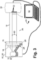
- the testing device of FIGURE 3 includes most of the same components as that of FIGURE 1 , and in particular includes passband illumination source 10 comprising light emitting element 12, optional beam-forming optical element(s) 14, and optional spectrum-shaping element(s) 16 cooperatively producing output passband illumination 18; and stopband illumination source 20 comprising light emitting element 22, optional beam-forming optical element(s) 24, and optional spectrum-shaping element(s) 26 cooperatively producing output stopband illumination 28; and photodetector element 30 with two-dimensional array of photodetectors 32; and electronic controller 40 with display component 42.
- passband illumination source 10 comprising light emitting element 12, optional beam-forming optical element(s) 14, and optional spectrum-shaping element(s) 16 cooperatively producing output passband illumination 18
- stopband illumination source 20 comprising light emitting element 22, optional beam-forming optical element(s) 24, and optional spectrum-shaping element(s) 26 cooperatively producing output stopband illumination 28
- photodetector element 30 with two-dimensional array of photodetectors 32
- electronic controller 40
- the testing device of FIGURE 3 omits the optical multiplexing component or sub-system 34 in favor of a laterally offset arrangement of the two illumination sources 10, 20 which produces the respective passband illumination 18 and stopband illumination 28 whose beam widths overlap over a common beam area 60 that is large enough to span the entire active area of the filter F under test.
- the two illumination sources 10, 20 may optionally share one or more beam-forming elements and/or one or more spectrum-shaping elements.
- the testing system of FIGURE 3 can be employed using the same method as that described previously with reference to FIGURE 2 .
- FIGURES 1 and 3 are merely illustrative examples, and other optical configurations can be employed to selectively apply the passband illumination 18 from the passband illumination source 10, or the stopband illumination 28 from the stopband illumination source 20, to the optical filter F under test.
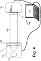
- a single illumination source 110 replaces both illumination sources 10, 20.
- the single illumination source 110 again includes a light emitting element 112, optional beam-forming optical element(s) 114, and optional spectrum-shaping element(s) 116 that cooperatively produce output illumination 118 which illuminates the filter F under test and, after transmission (where it occurs in view of the passband/stopband configuration of the filter F as further impacted by any point flaws) is detected by the photodetector element 30 with two-dimensional array of photodetectors 32 and analyzed by the electronic controller 40 with display component 42.
- the test device configuration of FIGURE 4 with its single illumination source 110 can be employed in various ways, some non-limiting examples of which are set forth in the following.
- the light emitting element 112 is switchable between emitting illumination 118 in the passband of the filter F under test and in the stopband of the filter F under test.
- the test device of FIGURE 4 can execute the point flaws test method of FIGURE 2 , except that operation Op2 entails switching the light emitting element 112 to emit passband illumination and operation Op6 entails switching the light emitting element 112 to emit stopband illumination.
- the light emitting element 112 emits broadband illumination over a spectral range that encompasses (or at least overlaps) both the passband and the stopband of the optical filter F under test.
- the spectrum-shaping element(s) 116 include a switchable spectral filter that selectively emits light in the passband or stopband of the filter F.
- the switchable spectrum-shaping element(s) 116 include a rotating filter wheel 116 w with a passband filter section 116p and a stopband filter section 116s.
- the output illumination which illuminates the filter F under test is the passband illumination 118p ( FIGURE 5 ); whereas, when rotation of the filter wheel 116 w brings the stopband filter section 116 S into intersection with broadband illumination from the broadband light emitting element 112, the output illumination which illuminates the filter F under test is the stopband illumination 118s ( FIGURE 6 ).
- the configuration also can perform the method of FIGURE 2 , except that when using the apparatus of FIGURES 4-6 the operation Op2 is effectuated by rotation of the filter wheel 116 w into the position shown in FIGURE 5 and the operation Op6 is effectuated by rotation of the filter wheel 116 w into the position shown in FIGURE 6 .
- the filter wheel 116 w rotates continuously and in an open-loop fashion, and operations Op2 , Op6 are performed by real-time analysis of the integrated signal output by the photodetector element 30 - with the filter wheel 116 w in the position of FIGURE 5 the summed output of the array of photodetectors 32 will be high and in this state operation Op3 is performed to acquire the passband map, while when the filter wheel 116 w rotates to the position of FIGURE 6 the summed output of the array of photodetectors 32 will be low and in this state operation Op7 is performed to acquire the stopband map.
- the illustrative filter wheel 116 w has two sections 116p, 116s each spanning 180° of the filter wheel 116 w , in other embodiments there may be, e.g. four alternating sections: a passband filter section spanning 90° followed by a stopband filter section spanning 90° followed by a passband filter section spanning 90° followed by a stopband filter section spanning 90°.
- one instance of the test device of FIGURE 4 is used to perform only the test 50 for pinholes, in which case the single illumination source 110 is suitably equivalent to the passband illumination source 10 of FIGURES 1 and 3 ; and, another instance of the test device of FIGURE 4 is used to perform only the test 52 for point defects, in which case the single illumination source 110 is suitably equivalent to the stopband illumination source 20 of FIGURES 1 and 3 .
- the filter F under test is suitably first inserted into the passband test device to perform the passband test, and then inserted into the stopband test device to perform the stopband test (or, this test order may be reversed).
- the test device should be configured to not simultaneously apply both the passband illumination and the stopband illumination.
- the optical filter F under test is illuminated with only the passband illumination (via operation Op2 ) during the passband test 50; and similarly the optical filter F under test is illuminated with only the stopband illumination (via operation Op6 ) during the stopband test 52.
- the passband illumination should have a spectral range that at least overlaps a passband of the optical filter under test; and similarly the stopband illumination should have a spectral range that lies entirely outside of the passband of the optical filter under test (and preferably lies within the design-basis spectrum of the optical filter under test).
- the passband illumination and/or the stopband illumination may be monochromatic.
- the two-dimensional array of photodetectors 32 is arranged to detect the passband illumination after passing through the filter under test and to detect the stopband illumination after passing through the filter under test.
- test devices disclosed herein for characterizing for point flaws of an optical filter under test does not acquire any spectral data for the optical filter under test, and hence the point flaws test is efficient.
- another test device used to perform the filter spectral characterization operation 54 does acquire spectral data for the optical filter under test - this other test device typically acquires spectral data at one, or at most a few, discrete points over the area of the filter under test, and hence is not efficient at detecting or characterizing point flaws of the filter under test. It is thus appreciated that the disclosed test devices for characterizing point flaws (e.g.
- devices of FIGURES 1 , 3 , or 4 performing the method of FIGURE 2 or a variant thereof) operate synergistically with a conventional optical filter spectral characterization test device (e.g., including a spectrometer or spectrograph) to more completely characterize the optical filter under test respective to both to confirm the filter specification is met (e.g. passband center wavelength and FWHM, cutoff slope, et cetera) and to ensure the optical filter is not defective due to a high number, density, and/or size of point flaws (stopband light-transmissive pinholes and/or passband light-blocking point defects).
- a conventional optical filter spectral characterization test device e.g., including a spectrometer or spectrograph
Applications Claiming Priority (3)
| Application Number | Priority Date | Filing Date | Title |
|---|---|---|---|
| US201562170310P | 2015-06-03 | 2015-06-03 | |
| EP16729170.7A EP3304057A1 (de) | 2015-06-03 | 2016-06-03 | Automatisierte defekterkennung und -abbildung für optische filter |
| PCT/US2016/035697 WO2016196917A1 (en) | 2015-06-03 | 2016-06-03 | Automated defect detection and mapping for optical filters |
Related Parent Applications (1)
| Application Number | Title | Priority Date | Filing Date |
|---|---|---|---|
| EP16729170.7A Division EP3304057A1 (de) | 2015-06-03 | 2016-06-03 | Automatisierte defekterkennung und -abbildung für optische filter |
Publications (1)
| Publication Number | Publication Date |
|---|---|
| EP4099003A1 true EP4099003A1 (de) | 2022-12-07 |
Family
ID=56121234
Family Applications (2)
| Application Number | Title | Priority Date | Filing Date |
|---|---|---|---|
| EP22187617.0A Pending EP4099003A1 (de) | 2015-06-03 | 2016-06-03 | Automatisierte defekterkennung und -abbildung für optische filter |
| EP16729170.7A Pending EP3304057A1 (de) | 2015-06-03 | 2016-06-03 | Automatisierte defekterkennung und -abbildung für optische filter |
Family Applications After (1)
| Application Number | Title | Priority Date | Filing Date |
|---|---|---|---|
| EP16729170.7A Pending EP3304057A1 (de) | 2015-06-03 | 2016-06-03 | Automatisierte defekterkennung und -abbildung für optische filter |
Country Status (4)
| Country | Link |
|---|---|
| US (1) | US9927369B2 (de) |
| EP (2) | EP4099003A1 (de) |
| CN (2) | CN107667287B (de) |
| WO (1) | WO2016196917A1 (de) |
Families Citing this family (9)
| Publication number | Priority date | Publication date | Assignee | Title |
|---|---|---|---|---|
| DE102016103070A1 (de) * | 2016-02-22 | 2017-08-24 | Texmag Gmbh Vertriebsgesellschaft | Inspektions- und/oder Bahnbeobachtungsvorrichtung, Verwendung einer Anordnung als Hintergrundblende oder Durchlichtsender in der Inspektions- und/oder der Bahnbeobachtungsvorrichtung und Verfahren zum Betreiben der Inspektions- und/oder Bahnbeobachtungsvorrichtung |
| JP7005620B2 (ja) * | 2016-12-09 | 2022-01-21 | フォームファクター, インコーポレイテッド | Cmos画像走査デバイスを試験するためのled光源プローブカード技術 |
| CN108387367A (zh) * | 2018-03-07 | 2018-08-10 | 宁波吉欧光电科技有限公司 | 一种光敏二极管的测试方法 |
| US11067389B2 (en) * | 2018-03-13 | 2021-07-20 | Kla Corporation | Overlay metrology system and method |
| CN109990978B (zh) * | 2019-04-10 | 2022-03-25 | 深圳市金视达光电有限公司 | 一种镜头ir波长的检测设备 |
| CN110007291B (zh) * | 2019-04-16 | 2021-07-02 | 深圳市速腾聚创科技有限公司 | 一种接收系统和激光雷达 |
| CN110148141B (zh) * | 2019-05-21 | 2023-07-25 | 东莞市瑞图新智科技有限公司 | 一种丝印滤光片小片检测计数方法及设备 |
| CN110676155B (zh) * | 2019-09-27 | 2021-12-10 | 上海中欣晶圆半导体科技有限公司 | 一种检测抛光硅片表面浅在缺陷的方法 |
| CN112033648B (zh) * | 2020-09-10 | 2022-03-08 | 重庆理工大学 | 滤光片的截止深度检测方法 |
Citations (13)
| Publication number | Priority date | Publication date | Assignee | Title |
|---|---|---|---|---|
| EP0515273A1 (de) * | 1991-05-23 | 1992-11-25 | Automobiles Peugeot | Optische Vorrichtung zur Erkennung von Farbtönen an Fenstern |
| JPH06208017A (ja) * | 1993-01-11 | 1994-07-26 | Sony Corp | カラーフィルターの欠陥検査方法および欠陥検査装置 |
| EP0711988A2 (de) * | 1994-11-10 | 1996-05-15 | TZN Forschungs- und Entwicklungszentrum Unterlüss GmbH | Messgerät zur Überprüfung von Graufiltern |
| US6088112A (en) * | 1998-06-27 | 2000-07-11 | Hyundai Electronics Industries Co., Ltd. | Image sensor having test patterns for measuring characteristics of color filters |
| US20030184741A1 (en) * | 2002-03-29 | 2003-10-02 | Dainippon Screen Mfg. Co., Ltd. | Color filter inspection apparatus |
| JP2004117062A (ja) * | 2002-09-24 | 2004-04-15 | Seiko Epson Corp | 電気光学パネル用基板の検査方法、電気光学パネル用基板の製造方法、電気光学パネル用基板、電気光学装置および電子機器 |
| JP2005148670A (ja) * | 2003-11-20 | 2005-06-09 | Seiko Epson Corp | 液晶パネルの検査画像作成方法及び装置並びに外観検査方法及び装置 |
| US7068430B1 (en) * | 2003-05-06 | 2006-06-27 | Semrock, Inc. | Method of making highly discriminating optical edge filters and resulting products |
| US20070247619A1 (en) * | 2006-04-24 | 2007-10-25 | Icf Technology Limited | Inspecting system for color filters |
| US20090097030A1 (en) * | 2007-10-16 | 2009-04-16 | Hon Hai Precision Industry Co., Ltd. | System and method for checking filter segment arrangement of a color filter in a color wheel |
| US20090190134A1 (en) * | 2004-07-30 | 2009-07-30 | Toru Shirai | Method and apparatus for inspecting color filter |
| JP2010256113A (ja) * | 2009-04-23 | 2010-11-11 | Toppan Printing Co Ltd | カラーフィルタの外観検査方法及び外観検査装置 |
| US20140299745A1 (en) * | 2009-12-07 | 2014-10-09 | Uti Limited Partnership | Apparatus, system, and method for emission filter |
Family Cites Families (8)
| Publication number | Priority date | Publication date | Assignee | Title |
|---|---|---|---|---|
| US5786891A (en) * | 1997-03-11 | 1998-07-28 | Lucent Technologies Inc. | Method and apparatus for detecting defects in an optical fiber coating |
| CN100334471C (zh) * | 2005-09-02 | 2007-08-29 | 中国科学院上海技术物理研究所 | 具有多腔结构的窄带滤光片列阵 |
| CN100547374C (zh) * | 2006-06-01 | 2009-10-07 | 友达光电股份有限公司 | 用于一彩色滤光片的检测系统及方法 |
| WO2007145223A1 (ja) * | 2006-06-12 | 2007-12-21 | Sharp Kabushiki Kaisha | 起伏検査装置、起伏検査方法、起伏検査装置の制御プログラム、記録媒体 |
| JP4597946B2 (ja) * | 2006-06-12 | 2010-12-15 | シャープ株式会社 | 端部傾斜角測定方法、起伏を有する被検査物の検査方法および検査装置 |
| US8958156B1 (en) * | 2007-05-30 | 2015-02-17 | Semrock, Inc. | Interference filter for non-zero angle of incidence spectroscopy |
| WO2011019974A2 (en) * | 2009-08-14 | 2011-02-17 | Arizona Board Of Regents, For And On Behalf Of Arizona State University | Method and system for aligning color filter array |
| KR20150007719A (ko) * | 2013-07-12 | 2015-01-21 | 동우 화인켐 주식회사 | 편광판의 검사 방법 |
-
2016
- 2016-06-03 CN CN201680032192.1A patent/CN107667287B/zh active Active
- 2016-06-03 CN CN202110500354.2A patent/CN113218966A/zh active Pending
- 2016-06-03 US US15/172,592 patent/US9927369B2/en active Active
- 2016-06-03 WO PCT/US2016/035697 patent/WO2016196917A1/en unknown
- 2016-06-03 EP EP22187617.0A patent/EP4099003A1/de active Pending
- 2016-06-03 EP EP16729170.7A patent/EP3304057A1/de active Pending
Patent Citations (13)
| Publication number | Priority date | Publication date | Assignee | Title |
|---|---|---|---|---|
| EP0515273A1 (de) * | 1991-05-23 | 1992-11-25 | Automobiles Peugeot | Optische Vorrichtung zur Erkennung von Farbtönen an Fenstern |
| JPH06208017A (ja) * | 1993-01-11 | 1994-07-26 | Sony Corp | カラーフィルターの欠陥検査方法および欠陥検査装置 |
| EP0711988A2 (de) * | 1994-11-10 | 1996-05-15 | TZN Forschungs- und Entwicklungszentrum Unterlüss GmbH | Messgerät zur Überprüfung von Graufiltern |
| US6088112A (en) * | 1998-06-27 | 2000-07-11 | Hyundai Electronics Industries Co., Ltd. | Image sensor having test patterns for measuring characteristics of color filters |
| US20030184741A1 (en) * | 2002-03-29 | 2003-10-02 | Dainippon Screen Mfg. Co., Ltd. | Color filter inspection apparatus |
| JP2004117062A (ja) * | 2002-09-24 | 2004-04-15 | Seiko Epson Corp | 電気光学パネル用基板の検査方法、電気光学パネル用基板の製造方法、電気光学パネル用基板、電気光学装置および電子機器 |
| US7068430B1 (en) * | 2003-05-06 | 2006-06-27 | Semrock, Inc. | Method of making highly discriminating optical edge filters and resulting products |
| JP2005148670A (ja) * | 2003-11-20 | 2005-06-09 | Seiko Epson Corp | 液晶パネルの検査画像作成方法及び装置並びに外観検査方法及び装置 |
| US20090190134A1 (en) * | 2004-07-30 | 2009-07-30 | Toru Shirai | Method and apparatus for inspecting color filter |
| US20070247619A1 (en) * | 2006-04-24 | 2007-10-25 | Icf Technology Limited | Inspecting system for color filters |
| US20090097030A1 (en) * | 2007-10-16 | 2009-04-16 | Hon Hai Precision Industry Co., Ltd. | System and method for checking filter segment arrangement of a color filter in a color wheel |
| JP2010256113A (ja) * | 2009-04-23 | 2010-11-11 | Toppan Printing Co Ltd | カラーフィルタの外観検査方法及び外観検査装置 |
| US20140299745A1 (en) * | 2009-12-07 | 2014-10-09 | Uti Limited Partnership | Apparatus, system, and method for emission filter |
Also Published As
| Publication number | Publication date |
|---|---|
| CN113218966A (zh) | 2021-08-06 |
| US20160356724A1 (en) | 2016-12-08 |
| CN107667287A (zh) | 2018-02-06 |
| US9927369B2 (en) | 2018-03-27 |
| WO2016196917A1 (en) | 2016-12-08 |
| EP3304057A1 (de) | 2018-04-11 |
| CN107667287B (zh) | 2021-05-25 |
Similar Documents
| Publication | Publication Date | Title |
|---|---|---|
| US9927369B2 (en) | Automated defect detection and mapping for optical filters | |
| EP1943502B1 (de) | Vorrichtungen und verfahren zur überprüfung einer verbundstruktur auf defekte | |
| CN107110782B (zh) | 宽带隙半导体基板的缺陷检查方法和缺陷检查装置 | |
| CN109540853B (zh) | 用于样本的缺陷检测及光致发光测量的系统及方法 | |
| EP3164723B1 (de) | Verfahren für fehlererkennung in werkstücken | |
| EP2609418B1 (de) | Defektkontroll- und photolumineszenz-messsystem | |
| US8426223B2 (en) | Wafer edge inspection | |
| KR102003781B1 (ko) | 초분광영상화 기법을 이용한 글라스(Glass) 결함 검출 장치 | |
| US9766179B2 (en) | Chemical characterization of surface features | |
| US9747520B2 (en) | Systems and methods for enhancing inspection sensitivity of an inspection tool | |
| US20150009320A1 (en) | Visually inspecting optical fibers | |
| EP3532429A1 (de) | Optische messtechnik mit hohem durchsatz und hoher auflösung für reflektierende und durchlässige nanophotonische vorrichtungen | |
| US11538722B2 (en) | Optical diagnostics of semiconductor process using hyperspectral imaging | |
| JP7163060B2 (ja) | 迅速な複合材製造の高速度低ノイズインプロセスハイパースペクトル非破壊評価のためのシステム及び方法 | |
| KR20170049266A (ko) | 비전검사장치 및 비전검사방법 | |
| WO2014153344A1 (en) | Inspection system including parallel imaging paths with multiple and selectable spectral bands | |
| US9500582B2 (en) | Method for detecting buried layers | |
| JP2020529618A5 (de) | ||
| JP7136064B2 (ja) | 被検査体の表面検査装置および被検査体の表面検査方法 | |
| KR101403926B1 (ko) | 곡면 검사장치 | |
| KR101146922B1 (ko) | 웨이퍼 검사용 광학 검출모듈 | |
| JP2009079979A (ja) | 周期性パターン試料検査装置 | |
| JP2007205743A (ja) | 着色膜厚ムラ検査方法および装置 |
Legal Events
| Date | Code | Title | Description |
|---|---|---|---|
| PUAI | Public reference made under article 153(3) epc to a published international application that has entered the european phase |
Free format text: ORIGINAL CODE: 0009012 |
|
| STAA | Information on the status of an ep patent application or granted ep patent |
Free format text: STATUS: THE APPLICATION HAS BEEN PUBLISHED |
|
| AC | Divisional application: reference to earlier application |
Ref document number: 3304057 Country of ref document: EP Kind code of ref document: P |
|
| AK | Designated contracting states |
Kind code of ref document: A1 Designated state(s): AL AT BE BG CH CY CZ DE DK EE ES FI FR GB GR HR HU IE IS IT LI LT LU LV MC MK MT NL NO PL PT RO RS SE SI SK SM TR |
|
| STAA | Information on the status of an ep patent application or granted ep patent |
Free format text: STATUS: REQUEST FOR EXAMINATION WAS MADE |
|
| 17P | Request for examination filed |
Effective date: 20230606 |
|
| P01 | Opt-out of the competence of the unified patent court (upc) registered |
Effective date: 20230530 |
|
| RBV | Designated contracting states (corrected) |
Designated state(s): AL AT BE BG CH CY CZ DE DK EE ES FI FR GB GR HR HU IE IS IT LI LT LU LV MC MK MT NL NO PL PT RO RS SE SI SK SM TR |