EP4098538B1 - Vertäuungsvorrichtung - Google Patents
Vertäuungsvorrichtung Download PDFInfo
- Publication number
- EP4098538B1 EP4098538B1 EP20916575.2A EP20916575A EP4098538B1 EP 4098538 B1 EP4098538 B1 EP 4098538B1 EP 20916575 A EP20916575 A EP 20916575A EP 4098538 B1 EP4098538 B1 EP 4098538B1
- Authority
- EP
- European Patent Office
- Prior art keywords
- connecting member
- weight structure
- seabed
- mooring
- floating body
- Prior art date
- Legal status (The legal status is an assumption and is not a legal conclusion. Google has not performed a legal analysis and makes no representation as to the accuracy of the status listed.)
- Active
Links
Images







Classifications
-
- B—PERFORMING OPERATIONS; TRANSPORTING
- B63—SHIPS OR OTHER WATERBORNE VESSELS; RELATED EQUIPMENT
- B63B—SHIPS OR OTHER WATERBORNE VESSELS; EQUIPMENT FOR SHIPPING
- B63B21/00—Tying-up; Shifting, towing, or pushing equipment; Anchoring
- B63B21/50—Anchoring arrangements or methods for special vessels, e.g. for floating drilling platforms or dredgers
-
- B—PERFORMING OPERATIONS; TRANSPORTING
- B63—SHIPS OR OTHER WATERBORNE VESSELS; RELATED EQUIPMENT
- B63B—SHIPS OR OTHER WATERBORNE VESSELS; EQUIPMENT FOR SHIPPING
- B63B21/00—Tying-up; Shifting, towing, or pushing equipment; Anchoring
- B63B21/24—Anchors
- B63B21/26—Anchors securing to bed
- B63B21/29—Anchors securing to bed by weight, e.g. flukeless weight anchors
-
- Y—GENERAL TAGGING OF NEW TECHNOLOGICAL DEVELOPMENTS; GENERAL TAGGING OF CROSS-SECTIONAL TECHNOLOGIES SPANNING OVER SEVERAL SECTIONS OF THE IPC; TECHNICAL SUBJECTS COVERED BY FORMER USPC CROSS-REFERENCE ART COLLECTIONS [XRACs] AND DIGESTS
- Y02—TECHNOLOGIES OR APPLICATIONS FOR MITIGATION OR ADAPTATION AGAINST CLIMATE CHANGE
- Y02E—REDUCTION OF GREENHOUSE GAS [GHG] EMISSIONS, RELATED TO ENERGY GENERATION, TRANSMISSION OR DISTRIBUTION
- Y02E10/00—Energy generation through renewable energy sources
- Y02E10/70—Wind energy
- Y02E10/727—Offshore wind turbines
Definitions
- the present disclosure relates to a mooring device, and more particularly, to a mooring device used to moor a floating offshore wind power generator and capable of minimizing the length of a connecting member required for mooring in deep water and minimizing an installation area as well as firmly and stably mooring a floating body.
- FIGS. 1 and 2 two types of methods have been used to fix a floating body in a floating offshore wind power generators according to the related art.
- one of the two types is a catenary type according to which a plurality of anchors 2 are drawn in various directions and deeply inserted into a seabed 1, and each of the anchors 2 is diagonally connected to a floating body 4 (a floating body of so-called spar type or semi-submersible type) by using a mooring chain 3 (or a mooring rope).
- the other one type is a taut type according to which the anchor 2 is fixed to the seabed 1 and by extending the mooring chain 3 (or a mooring rope) in a direction perpendicular to the anchor 2 to maintain tension, a floating body (so-called tension lag platform (TLP) type) is moored.
- TLP tension lag platform
- KR 100,976,615 , FR 2,669,295 , KR 101,292,236 and GB 2,500,322 disclose background art.
- the present disclosure pertaining to a mooring device used to moor a floating offshore wind power generator is devised to resolve the foregoing issues and aims to provide a mooring device capable of minimizing the length of a connecting member required for mooring in deep water and minimizing an installation area as well as firmly and stably mooring a floating body.
- a mooring device includes: a weight structure which sinks by gravity to be seated on a seabed; an anchor portion which is settled on the seabed to anchor a floating body; and a connecting member which includes one end portion connected to the floating body and the other end portion connected to the anchor portion, and has an extension direction that is changed by passing through a direction changing portion provided in the weight structure.
- the direction changing portion includes: a rotating portion arranged to be rotatable around a rotation shaft provided in the weight structure; a holding portion provided at one end portion of the rotating portion and configured to hold inward and extend the connecting member; and a fixer provided at the other end portion of the rotating portion and fixed in the seabed when the rotating portion is rotated by tension of the connecting member.
- a connecting member is connected and extends in the vertical direction from a weight structure to a floating body (e.g., a floating body for a floating offshore wind power generator) by a direction changing portion provided at the weight structure and extends and is anchored in a direction adjoining the seabed from the weight structure to an anchor portion, the technical stability and economic efficiency may be improved remarkably.
- the connecting member required for mooring may be minimized, and as the connecting member is connected vertically from the floating body to the weight structure, an area required for installation of the floating offshore wind power generator may be minimized as well.
- the grip force by the anchor portion may be secured sufficiently, which lead to the effect of firmly and stably mooring the floating body.
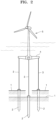
- FIG. 3 is a diagram of a mooring device according to an embodiment of the present disclosure
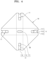
- FIG. 4 is a plan view of FIG. 3
- FIG. 5 is a front view of a mooring device according to another embodiment of the present disclosure
- FIG. 6 is a plan view of FIG. 5
- FIGS. 7 to 9 are diagrams illustrating an embodiment in which a fixing portion is coupled to a weight structure.
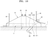
- FIG. 10 is a diagram illustrating an embodiment in which a different type of direction changing portion is applied
- FIG. 11 is a diagram illustrating an embodiment in which another type of weight structure is applied.
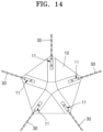
- FIGS. 12 to 15 are diagrams illustrating modification examples of a shape of a weight structure.
- a mooring device 100 relates to a device configured to moor a floating body which floats on a water surface.
- the mooring device 100 of the present disclosure may be used to fix a floating offshore wind power generator which floats on a water surface.
- the mooring device 100 may include a weight structure 10, an anchor portion 20, and a connecting member 30.
- the weight structure 10 may sink by gravity and be seated on a seabed.
- the weight structure 10 may have a weight sufficient to fix a floating body such as a floating offshore wind power generator.
- the weight structure 10 may be made of reinforced concrete or steel concrete. However, the material of the weight structure 10 is not limited to the foregoing, and the weight structure 10 may include various materials.
- a lug 50 for refloat and installation may be formed on the weight structure 10.
- the weight structure 10 may include a direction changing portion 11 configured to change an extension direction of the connecting member 30.
- the direction changing portion 11 may be arranged in such a manner that a part of the connecting member 30 extending upwards from the direction changing portion 11 is arranged downwards vertically from the floating body, and a part of the connecting member 30 directed towards the seabed by the direction changing portion 11 extends in the horizontal direction.
- the anchor portion 20 may be arranged to be settled on the seabed and anchor the floating body. According to the embodiment, a plurality of anchor portions 20 may be provided to be settled on the seabed and moor the floating body, together with the weight structure 10.
- the connecting member 30 may be component connecting the anchor portion 20 to the floating body.
- a chain, a wire rope, etc., which are commonly employed in a mooring device, may be used as the connecting member 30.
- One end portion of the connecting member 30 may be connected to the floating body, and the other end portion may be connected to the anchor portion 20.
- the extension direction of the connecting member 30 may be changed when the connecting member 30 passes through the direction changing portion 11 provided at the weight structure 10.
- the weight structure 10 may have a structure of a regular polygon.
- the direction changing portion 11 may change the extension direction of the connecting member 30 to a direction towards each vertex of the regular polygon from the center of the regular polygon. That is, the extension direction of the connecting member 30 extending downwards vertically may be changed to a direction towards a lateral side of the weight structure 10 by the direction changing portion 11.
- the direction changing portion 11 may change the extension direction of the connecting member 30 to the horizontal direction.
- the weight structure 10 may be formed in a shape of a square, and the connecting member 30 may proceed in a direction of an arrow by the direction changing portion 11.
- the shape of the weight structure 10 may be modified to a triangle, a quadrangle, a pentagon, a hexagon, etc.
- a plurality of direction changing portions 11 may be provided at the weight structure 10, and each of connecting members 30 may be provided to pass through each direction changing portion 11.
- the direction changing portion 11 may include a first opening 111, a second opening 112, and a wheel portion 113.
- the first opening 111 may be a part opened in an upward direction, and the connecting member 30 may extend upwards vertically through the first opening 111.
- the second opening 112 may be a part opened in a lateral direction, and the connecting member 30 may extend horizontally in the lateral direction through the second opening 112.
- the wheel portion 113 may be arranged between the first opening 111 and the second opening 112 and configured to change the extension direction of the connecting member 30.
- the wheel portion 113 may be in contact with the connecting member 30. That is, the direction of the connecting member 30 may be turned and changed at the wheel portion 113.
- the extension direction of the connecting member 30 may be changed by the direction changing portion 11 of the weight structure 10.
- the connecting member 30 may extend downwards vertically from the floating body to the weight structure 10.
- the connecting member 30 may extend horizontally from the weight structure 10 to the anchor portion 20.
- Such structure may implement both of the catenary type mooring method and the taut type mooring method simultaneously and thus be able to provide advantages of both types of the mooring method.
- the catenary type is a type according to which a mooring chain (or a mooring rope) is arranged diagonally from a floating body to a seabed to moor the floating body.
- a length of the chain or a rope required for mooring may increase in the deep water. Accordingly, not only the expense for such chain or rope increases, but also an occupied or used area of a floating offshore wind power generator may also increase, and fishery activities by fishing vessels may be directly disturbed.
- the taut type is a type according to which a mooring chain (or a mooring rope) is arranged vertically from the floating body to the seabed to moor the floating body.
- a mooring chain or a mooring rope
- the chain should be fixed securely to the seabed vertically, and strong tensile force needs to be maintained, which may be technically challenging.
- the connecting member 30 may be arranged vertically from the floating body to the direction changing portion 11 by the weight structure 10 which sinks to the seabed by gravity. Accordingly, the present disclosure may provide the advantage of the taut type mooring method. That is, as the connecting member 30 is arranged vertically, the cost necessary for the expensive connecting member 30 may be saved, and an occupied or used area of a public water surface required for a floating offshore wind power generator may be reduced. Moreover, the fishery activities of fishing vessels may not be overly disturbed.
- the connecting member 30 may extend adjoining the seabed from the direction changing portion 11 to the anchor portion 20.
- the connecting member 30 extends adjoining the seabed, and the anchor portion 20 is coupled to an end portion of the connecting member 30, the tensile force at an anchor point may work horizontally instead of vertically or diagonally. Accordingly, the stability of the mooring device 100 may be enhanced by increasing the fixation force.
- the connecting member 30 may extend adjoining the seabed, and one end of portion of the connecting member 30 is coupled to the anchor portion 20, sufficient fixation force may be secured in the deep water.
- the present disclosure may provide the effect of convenient construction or installation without employing a separate complex fixing device for improving the fixation force as in the taut type mooring method. That is, the mooring device 100 according to the present disclosure may resolve the technical issue concerning a fixing device used to fix a mooring device when a floating offshore wind power generator of tension leg platform (TLP) type, which requires vertical tensile force, is deployed.
- TLP tension leg platform
- FIGS. 5 to 11 are diagrams of the mooring device 100 according to another embodiment of the present disclosure.
- components acting or functioning the same as in FIG. 3 are denoted by the same reference numerals as in FIG. 3 , and any redundant description thereon is omitted.
- the mooring device 100 may have a different direction changing portion, compared to the embodiment of FIG. 3 .
- the rest of the components are substantially identical to the components of FIG. 3 .
- the direction changing portion 11 according to the embodiment may be formed in a tubular shape of which an inlet portion 114 opened in an upward direction and an outlet portion 115 opened in a lateral direction are connected to each other so that connecting member 30 passes through the direction changing portion 11.
- An inside of the tubular shape has a gentle curved surface so that the connecting member 30 may come out therethrough.
- the lug 50 for refloat and installation may be formed on the weight structure 10.
- the extension direction of the connecting member 30 may be changed when the connecting member 30 passes through the direction changing portion 11 having the tubular shape.
- the feature of extending vertically from the inlet portion 114 to the floating body and extending in a direction adjoining the seabed from the outlet portion 115 to the anchor portion 20 is the same in both direction changing portions.
- the actions and effects according to the embodiment are substantially identical to those of the embodiment according to FIG. 3 .
- a fixing portion 40 may be further provided to fix the weight structure 10 onto the seabed.
- the fixing portion 40 may protrude from a bottom surface of the weight structure 10 to be inserted into and fixed onto the seabed.
- the fixing portion 40 may include an insert portion 41 and a screw portion 42.
- the insert portion 41 may protrude from the bottom surface of the weight structure 10 to be inserted into the seabed.
- the screw portion 42 may be a spiral wing coupled to an outer circumferential surface of the insert portion 41 and be provided to facilitate the insertion of the fixing portion 40 into the seabed and to prevent the fixing portion 40 from being easily detached from the seabed. Accordingly, the fixing portion 40 having a shape of a screw may provide the effect of sufficiently improving the grip power while enduring the tensile force due to the buoyant force caused by the floating body.
- the fixing portion 40 may be formed in a pile type. Similar to the screw type, the pile type may also endure the strong tensile force formed by the buoyant force of the floating body and improve the grip force.
- a plurality of fixing portions 40 may be provided on the edge bottom surface of the weight structure 10.
- the fixing portion 40 formed in a corn shape at the edge of the weight structure 10 may improve the grip force of the weight structure 10 in the vertical direction and endure the tensile force when the connecting member 30 extends in a direction adjoining the seabed from the lateral side of the weight structure 10.
- FIG. 10 illustrates an embodiment in which the direction changing portion 11 is configured differently, compared to FIG. 3 .
- the direction changing portion 11 applied to the embodiment may include a rotating portion 61, a holding portion 62, and a fixer 63.
- the rotating portion is provided to be rotatable around a rotation shaft 60 provided in the weight structure 10.
- the rotating portion 61 may include a shaft hole 611 into which the rotation shaft 60 is inserted, a first rotation bar 612 and a second rotation bar 613 which extend from the shaft hole 611 in an opposite direction from each other.
- the holding portion 62 is provided at one end portion of the rotating portion 61 to hold inward and extend the connecting member 30.
- the holding portion 62 may be provided at an end portion of the first rotation bar 612.
- the connecting member 30 extending from the holding portion 62 towards the floating body may extend in the vertical direction.
- the extension direction of the connecting member 30 extending from the holding portion 62 towards the seabed may be changed from the vertical direction to be directed towards the seabed.
- the fixer 63 is provided at the other end portion of the rotating portion 61 and is fixed in the seabed when the rotating portion 61 is rotated by the tension of the connecting member 30.
- the fixer 63 may be coupled to one end of the second rotation bar 613 and be formed in a shape of a hook, and the second rotation bar 613 may burrow into the seabed and fix the weight structure 10 onto the seabed.
- the fixing portion 40 of rotating type may fix the weight structure 10 in the vertical direction and facilitate the bearing of the tensile force caused by the connecting member 30 pulled by the anchor portion 20 in the lateral direction.
- FIG. 11 illustrates an embodiment in which the weight structure 10 is configured differently, compared to FIG. 3 .
- the weight structure 10 applied to the embodiment may include a body portion 71 and a setting portion 72.
- a space portion 73 filled with an auxiliary weight may be formed at a center portion of the body portion 71.
- the body portion 71 may be formed in a cylindrical shape including a space therein.
- the shape of the body portion 71 is not limited to the cylindrical shape, and the body portion 71 may have any other shapes as long as it includes the space portion 73.
- the space portion 73 may be filled with rocks or a concrete weight 74.
- the fixing portion 40 may be applied to the seabed.
- the lugs 50 for installation and refloat may be arranged apart from each other on an upper surface of the body portion 71.
- the setting portion 72 may be radially coupled to an outer circumferential surface of the body portion 71 and may be seated on the seabed. A contact area between the body portion 71 and the seabed may be increased by the setting portion 72.
- the direction changing portion 11 may be formed at the setting portion 72.
- the configuration of the direction changing portion 11 may employ one of the forms applied to the embodiments.
Landscapes
- Chemical & Material Sciences (AREA)
- Engineering & Computer Science (AREA)
- Combustion & Propulsion (AREA)
- Mechanical Engineering (AREA)
- Ocean & Marine Engineering (AREA)
- Wind Motors (AREA)
Claims (1)
- Vertäuungsvorrichtung, umfassend:eine Gewichtsstruktur (10), die durch die Schwerkraft sinkt, um auf einem Meeresboden zu liegen;einen Ankerabschnitt (20), der auf dem Meeresboden aufgesetzt wird, um einen Schwimmkörper zu verankern; undein Verbindungselement (30), das einen Endabschnitt, der mit dem Schwimmkörper verbunden ist, und den anderen Endabschnitt beinhaltet, der mit dem Ankerabschnitt (20) verbunden ist, wobei das Verbindungselement (30) eine Ausdehnungsrichtung aufweist, die durch Passieren eines Richtungsänderungsabschnitts (11) geändert wird, der in der Gewichtsstruktur (10) bereitgestellt ist,dadurch gekennzeichnet, dass der Richtungsänderungsabschnitt umfasst:einen sich drehenden Abschnitt (61), der angeordnet ist, um um eine Drehwelle (60) drehbar zu sein, die in der Gewichtsstruktur bereitgestellt ist;einen Halteabschnitt (62), der an einem Endabschnitt des sich drehenden Abschnitts (61) bereitgestellt ist und dazu konfiguriert ist, das Verbindungselement (30) nach innen zu halten, sodass sich das Verbindungselement ausdehnt; undeinen Fixierer (63), der an dem anderen Endabschnitt des sich drehenden Abschnitts (61) bereitgestellt und in dem Meeresboden fixiert ist, wenn der sich drehende Abschnitt (61) durch die Spannung des Verbindungselements (30) gedreht wird.
Applications Claiming Priority (2)
| Application Number | Priority Date | Filing Date | Title |
|---|---|---|---|
| KR1020200010492A KR102209053B1 (ko) | 2020-01-29 | 2020-01-29 | 계류 장치 |
| PCT/KR2020/003279 WO2021153845A1 (ko) | 2020-01-29 | 2020-03-09 | 계류 장치 |
Publications (3)
| Publication Number | Publication Date |
|---|---|
| EP4098538A1 EP4098538A1 (de) | 2022-12-07 |
| EP4098538A4 EP4098538A4 (de) | 2024-03-27 |
| EP4098538B1 true EP4098538B1 (de) | 2025-06-11 |
Family
ID=74239235
Family Applications (1)
| Application Number | Title | Priority Date | Filing Date |
|---|---|---|---|
| EP20916575.2A Active EP4098538B1 (de) | 2020-01-29 | 2020-03-09 | Vertäuungsvorrichtung |
Country Status (3)
| Country | Link |
|---|---|
| EP (1) | EP4098538B1 (de) |
| KR (1) | KR102209053B1 (de) |
| WO (1) | WO2021153845A1 (de) |
Families Citing this family (7)
| Publication number | Priority date | Publication date | Assignee | Title |
|---|---|---|---|---|
| FR3121654B1 (fr) * | 2021-04-09 | 2023-04-21 | Pinarello Yacht Services | Dispositif de corps-mort pour l’amarrage de navires. |
| KR102413710B1 (ko) * | 2021-08-09 | 2022-06-28 | 주식회사 포어시스 | 개량형 버킷 앵커의 제조방법 및 설치방법 |
| KR102774959B1 (ko) * | 2022-05-20 | 2025-03-05 | 세호엔지니어링 주식회사 | 부유식 해양 구조물 계류용 앵커장치 |
| NL2032466B1 (en) * | 2022-07-12 | 2024-01-25 | Itrec Bv | Installation follower for installing plate anchors for floating wind turbines of a wind farm |
| US12291310B1 (en) | 2023-09-19 | 2025-05-06 | Terasun Co. Ltd. | Floating platform, anchor container structure, floating structure, and installation method for installing floating platform on water |
| JP7432975B1 (ja) * | 2023-09-19 | 2024-02-19 | 株式会社テラサン | 浮体式プラットフォーム、アンカー容器体、浮体、浮体式プラットフォームを水上に設置するための設置方法 |
| CN118668745B (zh) * | 2024-07-08 | 2025-03-04 | 天津理工大学 | 海上漂浮式光伏工程自适应栅栏式锚固基础及其应用方法 |
Family Cites Families (12)
| Publication number | Priority date | Publication date | Assignee | Title |
|---|---|---|---|---|
| FR2669295B1 (fr) * | 1990-11-21 | 1993-03-12 | Deshais Sophie | Ancre additionnelle pour ligne de mouillage comportant une ancre principale. |
| DE4310859C2 (de) | 1993-04-02 | 2002-11-28 | Bosch Gmbh Robert | Verfahren und Vorrichtung zur Positionierung einer Drosselklappe eines Kraftfahrzeuges |
| JP2520659Y2 (ja) * | 1993-06-11 | 1996-12-18 | 祥永 桜井 | 横置き係留用アンカー |
| KR200249015Y1 (ko) * | 2001-07-11 | 2001-11-17 | 홍광선 | 정박용 닻 |
| KR100976615B1 (ko) * | 2010-04-09 | 2010-08-17 | 부경엔지니어링주식회사 | 수질측정용 부이장치 |
| KR20120073100A (ko) * | 2010-12-24 | 2012-07-04 | 윤삼걸 | 부력체와 도르레를 이용한 해양생물 관측 장치 및 그 고정방법 |
| GB201206197D0 (en) * | 2012-04-05 | 2012-05-23 | Greenstick Energy Ltd | A mooring device |
| KR101292236B1 (ko) * | 2012-09-28 | 2013-07-31 | 신웅종합개발 주식회사 | 해상 구조물의 앵커 블록 |
| KR101722182B1 (ko) * | 2015-07-09 | 2017-03-31 | 삼성중공업 주식회사 | 앵커 장치 |
| KR101722212B1 (ko) * | 2015-07-24 | 2017-03-31 | 삼성중공업 주식회사 | 앵커 |
| KR101731278B1 (ko) * | 2016-02-18 | 2017-04-28 | 주식회사 인진 | 블럭형 파력 발전 장치 및 그 설치 방법 |
| KR102027577B1 (ko) * | 2017-12-27 | 2019-10-01 | 삼성중공업 주식회사 | 계류 장치 |
-
2020
- 2020-01-29 KR KR1020200010492A patent/KR102209053B1/ko active Active
- 2020-03-09 EP EP20916575.2A patent/EP4098538B1/de active Active
- 2020-03-09 WO PCT/KR2020/003279 patent/WO2021153845A1/ko not_active Ceased
Also Published As
| Publication number | Publication date |
|---|---|
| EP4098538A1 (de) | 2022-12-07 |
| WO2021153845A1 (ko) | 2021-08-05 |
| EP4098538A4 (de) | 2024-03-27 |
| KR102209053B1 (ko) | 2021-01-28 |
Similar Documents
| Publication | Publication Date | Title |
|---|---|---|
| EP4098538B1 (de) | Vertäuungsvorrichtung | |
| ES2503065T3 (es) | Sistema y procedimiento de módulo de turbina eólica flotante de eje vertical | |
| US9803328B2 (en) | Floatable support structure for an offshore wind turbine or other device | |
| US12202574B2 (en) | Buoyant structure for receiving a tower of a wind turbine in offshore deployment | |
| US20180170490A1 (en) | Floating wind turbine assembly, as well as a method for mooring such a floating wind turbine assembly | |
| CA2637358C (en) | Mooring system | |
| WO2022231511A1 (en) | A buoyant structure for receiving a tower of a wind turbine in offshore deployment | |
| US9499241B2 (en) | Floating offshore structures | |
| KR20130046192A (ko) | 해양 부유 구조물 및 이를 이용한 해상 부유식 풍력 발전장치 | |
| KR20180108195A (ko) | 부유식 해상 풍력발전설비 | |
| KR20200099387A (ko) | 세굴방지장치 | |
| JP6420971B2 (ja) | 水上風力発電装置用の基礎構造、水上風力発電装置および水上風力発電装置の製造方法 | |
| US20250313310A1 (en) | Asymmetric floating wind turbine installation | |
| KR200251484Y1 (ko) | 선박 정박용 닻 | |
| KR20250018394A (ko) | 계류 시스템 | |
| KR20130048643A (ko) | 해양 부유 구조물 및 이를 이용한 해양 부유식 풍력 발전장치 | |
| CN117284432A (zh) | 一种半潜式风电平台 | |
| JP2014533218A (ja) | 係留構成、及び、水中において浮体式ユニットを係留するとともに係留を解除する方法 | |
| US20250229870A1 (en) | Single shared anchor mooring systems and installation method for floating offshore wind turbines | |
| JP2020084813A (ja) | 浮体式洋上風力発電システム | |
| KR200266222Y1 (ko) | 정박용 앵커 | |
| KR200479276Y1 (ko) | 선박 및 해상부유구조물 정박용 닻 | |
| KR200297860Y1 (ko) | 정박용 앵커 | |
| KR20170011118A (ko) | 앵커 | |
| KR101607471B1 (ko) | 해류로부터 에너지를 발생시키기 위한 조립체 |
Legal Events
| Date | Code | Title | Description |
|---|---|---|---|
| STAA | Information on the status of an ep patent application or granted ep patent |
Free format text: STATUS: THE INTERNATIONAL PUBLICATION HAS BEEN MADE |
|
| PUAI | Public reference made under article 153(3) epc to a published international application that has entered the european phase |
Free format text: ORIGINAL CODE: 0009012 |
|
| STAA | Information on the status of an ep patent application or granted ep patent |
Free format text: STATUS: REQUEST FOR EXAMINATION WAS MADE |
|
| 17P | Request for examination filed |
Effective date: 20220704 |
|
| AK | Designated contracting states |
Kind code of ref document: A1 Designated state(s): AL AT BE BG CH CY CZ DE DK EE ES FI FR GB GR HR HU IE IS IT LI LT LU LV MC MK MT NL NO PL PT RO RS SE SI SK SM TR |
|
| DAV | Request for validation of the european patent (deleted) | ||
| DAX | Request for extension of the european patent (deleted) | ||
| A4 | Supplementary search report drawn up and despatched |
Effective date: 20240222 |
|
| RIC1 | Information provided on ipc code assigned before grant |
Ipc: B63B 21/29 20060101ALI20240216BHEP Ipc: B63B 21/50 20060101AFI20240216BHEP |
|
| GRAP | Despatch of communication of intention to grant a patent |
Free format text: ORIGINAL CODE: EPIDOSNIGR1 |
|
| STAA | Information on the status of an ep patent application or granted ep patent |
Free format text: STATUS: GRANT OF PATENT IS INTENDED |
|
| INTG | Intention to grant announced |
Effective date: 20250122 |
|
| GRAS | Grant fee paid |
Free format text: ORIGINAL CODE: EPIDOSNIGR3 |
|
| GRAA | (expected) grant |
Free format text: ORIGINAL CODE: 0009210 |
|
| STAA | Information on the status of an ep patent application or granted ep patent |
Free format text: STATUS: THE PATENT HAS BEEN GRANTED |
|
| AK | Designated contracting states |
Kind code of ref document: B1 Designated state(s): AL AT BE BG CH CY CZ DE DK EE ES FI FR GB GR HR HU IE IS IT LI LT LU LV MC MK MT NL NO PL PT RO RS SE SI SK SM TR |
|
| REG | Reference to a national code |
Ref country code: GB Ref legal event code: FG4D |
|
| REG | Reference to a national code |
Ref country code: CH Ref legal event code: EP |
|
| REG | Reference to a national code |
Ref country code: IE Ref legal event code: FG4D |
|
| REG | Reference to a national code |
Ref country code: DE Ref legal event code: R096 Ref document number: 602020052768 Country of ref document: DE |
|
| PG25 | Lapsed in a contracting state [announced via postgrant information from national office to epo] |
Ref country code: ES Free format text: LAPSE BECAUSE OF FAILURE TO SUBMIT A TRANSLATION OF THE DESCRIPTION OR TO PAY THE FEE WITHIN THE PRESCRIBED TIME-LIMIT Effective date: 20250611 Ref country code: FI Free format text: LAPSE BECAUSE OF FAILURE TO SUBMIT A TRANSLATION OF THE DESCRIPTION OR TO PAY THE FEE WITHIN THE PRESCRIBED TIME-LIMIT Effective date: 20250611 |
|
| REG | Reference to a national code |
Ref country code: LT Ref legal event code: MG9D |
|
| PG25 | Lapsed in a contracting state [announced via postgrant information from national office to epo] |
Ref country code: GR Free format text: LAPSE BECAUSE OF FAILURE TO SUBMIT A TRANSLATION OF THE DESCRIPTION OR TO PAY THE FEE WITHIN THE PRESCRIBED TIME-LIMIT Effective date: 20250912 Ref country code: NO Free format text: LAPSE BECAUSE OF FAILURE TO SUBMIT A TRANSLATION OF THE DESCRIPTION OR TO PAY THE FEE WITHIN THE PRESCRIBED TIME-LIMIT Effective date: 20250911 |
|
| REG | Reference to a national code |
Ref country code: NL Ref legal event code: MP Effective date: 20250611 |
|
| PG25 | Lapsed in a contracting state [announced via postgrant information from national office to epo] |
Ref country code: BG Free format text: LAPSE BECAUSE OF FAILURE TO SUBMIT A TRANSLATION OF THE DESCRIPTION OR TO PAY THE FEE WITHIN THE PRESCRIBED TIME-LIMIT Effective date: 20250611 |
|
| PG25 | Lapsed in a contracting state [announced via postgrant information from national office to epo] |
Ref country code: HR Free format text: LAPSE BECAUSE OF FAILURE TO SUBMIT A TRANSLATION OF THE DESCRIPTION OR TO PAY THE FEE WITHIN THE PRESCRIBED TIME-LIMIT Effective date: 20250611 |
|
| PG25 | Lapsed in a contracting state [announced via postgrant information from national office to epo] |
Ref country code: RS Free format text: LAPSE BECAUSE OF FAILURE TO SUBMIT A TRANSLATION OF THE DESCRIPTION OR TO PAY THE FEE WITHIN THE PRESCRIBED TIME-LIMIT Effective date: 20250911 |
|
| PG25 | Lapsed in a contracting state [announced via postgrant information from national office to epo] |
Ref country code: LV Free format text: LAPSE BECAUSE OF FAILURE TO SUBMIT A TRANSLATION OF THE DESCRIPTION OR TO PAY THE FEE WITHIN THE PRESCRIBED TIME-LIMIT Effective date: 20250611 |
|
| PG25 | Lapsed in a contracting state [announced via postgrant information from national office to epo] |
Ref country code: NL Free format text: LAPSE BECAUSE OF FAILURE TO SUBMIT A TRANSLATION OF THE DESCRIPTION OR TO PAY THE FEE WITHIN THE PRESCRIBED TIME-LIMIT Effective date: 20250611 |
|
| PG25 | Lapsed in a contracting state [announced via postgrant information from national office to epo] |
Ref country code: PT Free format text: LAPSE BECAUSE OF FAILURE TO SUBMIT A TRANSLATION OF THE DESCRIPTION OR TO PAY THE FEE WITHIN THE PRESCRIBED TIME-LIMIT Effective date: 20251013 |
|
| REG | Reference to a national code |
Ref country code: AT Ref legal event code: MK05 Ref document number: 1802158 Country of ref document: AT Kind code of ref document: T Effective date: 20250611 |
|
| PG25 | Lapsed in a contracting state [announced via postgrant information from national office to epo] |
Ref country code: IS Free format text: LAPSE BECAUSE OF FAILURE TO SUBMIT A TRANSLATION OF THE DESCRIPTION OR TO PAY THE FEE WITHIN THE PRESCRIBED TIME-LIMIT Effective date: 20251011 |
|
| PG25 | Lapsed in a contracting state [announced via postgrant information from national office to epo] |
Ref country code: AT Free format text: LAPSE BECAUSE OF FAILURE TO SUBMIT A TRANSLATION OF THE DESCRIPTION OR TO PAY THE FEE WITHIN THE PRESCRIBED TIME-LIMIT Effective date: 20250611 Ref country code: SM Free format text: LAPSE BECAUSE OF FAILURE TO SUBMIT A TRANSLATION OF THE DESCRIPTION OR TO PAY THE FEE WITHIN THE PRESCRIBED TIME-LIMIT Effective date: 20250611 |
|
| PG25 | Lapsed in a contracting state [announced via postgrant information from national office to epo] |
Ref country code: CZ Free format text: LAPSE BECAUSE OF FAILURE TO SUBMIT A TRANSLATION OF THE DESCRIPTION OR TO PAY THE FEE WITHIN THE PRESCRIBED TIME-LIMIT Effective date: 20250611 |
|
| PG25 | Lapsed in a contracting state [announced via postgrant information from national office to epo] |
Ref country code: PL Free format text: LAPSE BECAUSE OF FAILURE TO SUBMIT A TRANSLATION OF THE DESCRIPTION OR TO PAY THE FEE WITHIN THE PRESCRIBED TIME-LIMIT Effective date: 20250611 |
|
| PG25 | Lapsed in a contracting state [announced via postgrant information from national office to epo] |
Ref country code: EE Free format text: LAPSE BECAUSE OF FAILURE TO SUBMIT A TRANSLATION OF THE DESCRIPTION OR TO PAY THE FEE WITHIN THE PRESCRIBED TIME-LIMIT Effective date: 20250611 |
|
| PG25 | Lapsed in a contracting state [announced via postgrant information from national office to epo] |
Ref country code: SK Free format text: LAPSE BECAUSE OF FAILURE TO SUBMIT A TRANSLATION OF THE DESCRIPTION OR TO PAY THE FEE WITHIN THE PRESCRIBED TIME-LIMIT Effective date: 20250611 |
|
| REG | Reference to a national code |
Ref country code: DE Ref legal event code: R097 Ref document number: 602020052768 Country of ref document: DE |
|
| PGFP | Annual fee paid to national office [announced via postgrant information from national office to epo] |
Ref country code: GB Payment date: 20260106 Year of fee payment: 7 |
|
| PG25 | Lapsed in a contracting state [announced via postgrant information from national office to epo] |
Ref country code: DK Free format text: LAPSE BECAUSE OF FAILURE TO SUBMIT A TRANSLATION OF THE DESCRIPTION OR TO PAY THE FEE WITHIN THE PRESCRIBED TIME-LIMIT Effective date: 20250611 |
|
| PG25 | Lapsed in a contracting state [announced via postgrant information from national office to epo] |
Ref country code: IT Free format text: LAPSE BECAUSE OF FAILURE TO SUBMIT A TRANSLATION OF THE DESCRIPTION OR TO PAY THE FEE WITHIN THE PRESCRIBED TIME-LIMIT Effective date: 20250611 |
|
| PLBE | No opposition filed within time limit |
Free format text: ORIGINAL CODE: 0009261 |
|
| STAA | Information on the status of an ep patent application or granted ep patent |
Free format text: STATUS: NO OPPOSITION FILED WITHIN TIME LIMIT |
|
| REG | Reference to a national code |
Ref country code: CH Ref legal event code: L10 Free format text: ST27 STATUS EVENT CODE: U-0-0-L10-L00 (AS PROVIDED BY THE NATIONAL OFFICE) Effective date: 20260423 |