EP4097989B1 - Tragbares audiogerät mit kabeldurchgangsscharnier - Google Patents
Tragbares audiogerät mit kabeldurchgangsscharnier Download PDFInfo
- Publication number
- EP4097989B1 EP4097989B1 EP21706801.4A EP21706801A EP4097989B1 EP 4097989 B1 EP4097989 B1 EP 4097989B1 EP 21706801 A EP21706801 A EP 21706801A EP 4097989 B1 EP4097989 B1 EP 4097989B1
- Authority
- EP
- European Patent Office
- Prior art keywords
- hinge
- section
- cable
- audio device
- wearable audio
- Prior art date
- Legal status (The legal status is an assumption and is not a legal conclusion. Google has not performed a legal analysis and makes no representation as to the accuracy of the status listed.)
- Active
Links
Images




Classifications
-
- H—ELECTRICITY
- H04—ELECTRIC COMMUNICATION TECHNIQUE
- H04R—LOUDSPEAKERS, MICROPHONES, GRAMOPHONE PICK-UPS OR LIKE ACOUSTIC ELECTROMECHANICAL TRANSDUCERS; ELECTRIC HEARING AIDS; PUBLIC ADDRESS SYSTEMS
- H04R1/00—Details of transducers, loudspeakers or microphones
- H04R1/10—Earpieces; Attachments therefor ; Earphones; Monophonic headphones
- H04R1/1058—Manufacture or assembly
- H04R1/1066—Constructional aspects of the interconnection between earpiece and earpiece support
-
- G—PHYSICS
- G02—OPTICS
- G02C—SPECTACLES; SUNGLASSES OR GOGGLES INSOFAR AS THEY HAVE THE SAME FEATURES AS SPECTACLES; CONTACT LENSES
- G02C5/00—Constructions of non-optical parts
- G02C5/22—Hinges
- G02C5/2218—Resilient hinges
- G02C5/2227—Resilient hinges comprising a fixed hinge member and a coil spring
-
- G—PHYSICS
- G02—OPTICS
- G02C—SPECTACLES; SUNGLASSES OR GOGGLES INSOFAR AS THEY HAVE THE SAME FEATURES AS SPECTACLES; CONTACT LENSES
- G02C1/00—Assemblies of lenses with bridges or browbars
-
- G—PHYSICS
- G02—OPTICS
- G02C—SPECTACLES; SUNGLASSES OR GOGGLES INSOFAR AS THEY HAVE THE SAME FEATURES AS SPECTACLES; CONTACT LENSES
- G02C11/00—Non-optical adjuncts; Attachment thereof
- G02C11/06—Hearing aids
-
- G—PHYSICS
- G02—OPTICS
- G02C—SPECTACLES; SUNGLASSES OR GOGGLES INSOFAR AS THEY HAVE THE SAME FEATURES AS SPECTACLES; CONTACT LENSES
- G02C11/00—Non-optical adjuncts; Attachment thereof
- G02C11/10—Electronic devices other than hearing aids
-
- G—PHYSICS
- G02—OPTICS
- G02C—SPECTACLES; SUNGLASSES OR GOGGLES INSOFAR AS THEY HAVE THE SAME FEATURES AS SPECTACLES; CONTACT LENSES
- G02C5/00—Constructions of non-optical parts
- G02C5/22—Hinges
-
- H—ELECTRICITY
- H04—ELECTRIC COMMUNICATION TECHNIQUE
- H04R—LOUDSPEAKERS, MICROPHONES, GRAMOPHONE PICK-UPS OR LIKE ACOUSTIC ELECTROMECHANICAL TRANSDUCERS; ELECTRIC HEARING AIDS; PUBLIC ADDRESS SYSTEMS
- H04R1/00—Details of transducers, loudspeakers or microphones
- H04R1/08—Mouthpieces; Microphones; Attachments therefor
-
- H—ELECTRICITY
- H04—ELECTRIC COMMUNICATION TECHNIQUE
- H04R—LOUDSPEAKERS, MICROPHONES, GRAMOPHONE PICK-UPS OR LIKE ACOUSTIC ELECTROMECHANICAL TRANSDUCERS; ELECTRIC HEARING AIDS; PUBLIC ADDRESS SYSTEMS
- H04R1/00—Details of transducers, loudspeakers or microphones
- H04R1/10—Earpieces; Attachments therefor ; Earphones; Monophonic headphones
- H04R1/105—Earpiece supports, e.g. ear hooks
-
- H—ELECTRICITY
- H04—ELECTRIC COMMUNICATION TECHNIQUE
- H04R—LOUDSPEAKERS, MICROPHONES, GRAMOPHONE PICK-UPS OR LIKE ACOUSTIC ELECTROMECHANICAL TRANSDUCERS; ELECTRIC HEARING AIDS; PUBLIC ADDRESS SYSTEMS
- H04R5/00—Stereophonic arrangements
- H04R5/033—Headphones for stereophonic communication
- H04R5/0335—Earpiece support, e.g. headbands or neckrests
-
- G—PHYSICS
- G02—OPTICS
- G02C—SPECTACLES; SUNGLASSES OR GOGGLES INSOFAR AS THEY HAVE THE SAME FEATURES AS SPECTACLES; CONTACT LENSES
- G02C5/00—Constructions of non-optical parts
- G02C5/02—Bridges; Browbars; Intermediate bars
-
- H—ELECTRICITY
- H04—ELECTRIC COMMUNICATION TECHNIQUE
- H04R—LOUDSPEAKERS, MICROPHONES, GRAMOPHONE PICK-UPS OR LIKE ACOUSTIC ELECTROMECHANICAL TRANSDUCERS; ELECTRIC HEARING AIDS; PUBLIC ADDRESS SYSTEMS
- H04R2420/00—Details of connection covered by H04R, not provided for in its groups
- H04R2420/07—Applications of wireless loudspeakers or wireless microphones
Definitions
- This disclosure generally relates to audio eyeglasses. More particularly, the disclosure relates to audio eyeglasses with through-hinge wiring.
- Providing power and communications between components in electronic devices often involves running one or more cables through physically distinct sections of a housing or frame.
- the electronic device includes a hinge (e.g., in a wearable audio device) it can be challenging to design the hinge for accommodating the cable as well as the hinge mechanism.
- US 10 353 221 discloses audio eyeglasses with cable-through hinge.
- the present invention relates to audio eyeglasses as set forth in claim 1.
- Advantageous embodiments are recited in dependent claims of the appended set of claims.
- aspects of the disclosure generally relate to wearable audio devices such as audio eyeglasses or audio headsets with through-hinge wiring. More particularly, aspects of the disclosure relate to wearable audio devices having a hinge with an insert for managing a minimum bend radius of a cable and a cable management feature.
- the hinge includes a metal ledge that extends around the interface between sections of the wearable audio device.
- inboard and outboard are used to describe the radial location of components relative to the central axis (A), such that relative to the axis (A), a component that is radially inboard of a distinct component is closer to the central axis (A) on a radial (perpendicular) line that extends from the axis (A).
- radially oriented can be used to refer to a component, line, or plane that is perpendicular to an axis such as a central axis (A).
- Components shown and described herein can be formed according to various manufacturing techniques, for example, molding, casting, additive manufacturing (e.g., 3D printing), etc. Where specific techniques are not described, conventional manufacturing approaches can be used to form the components and structures disclosed according to various implementations. Particular implementations include manufacturing approaches such as overmolding, where a first portion of the component (substrate) is partially or fully covered by a subsequently formed portion of the component (overmold).
- wearable audio device includes headphones and various other types of personal audio devices such as head, shoulder or body-worn acoustic devices that include one or more acoustic drivers to produce sound, with or without contacting the ears of a user.
- Some aspects disclosed may be particularly applicable to personal (wearable) audio devices such as audio eyeglasses or other head-mounted audio devices.
- aspects and implementations disclosed herein may be applicable to speaker systems that either do or do not support two-way communications, and either do or do not support active noise reduction (ANR).
- ANR active noise reduction
- speaker systems that do support either two-way communications or ANR it is intended that what is disclosed and claimed herein is applicable to a speaker system incorporating one or more microphones disposed on a portion of the speaker system that remains outside an ear when in use (e.g., feedforward microphones), on a portion that is inserted into a portion of an ear when in use (e.g., feedback microphones), or disposed on both of such portions.
- Still other implementations of speaker systems to which what is disclosed and what is claimed herein is applicable will be apparent to those skilled in the art.
- Particular example implementations relate to off-ear headphones that produce sound using an acoustic driver that is spaced (or, separated) from the ear of the user while in use.
- Examples of off-ear headphones with dipole loudspeakers are disclosed in U.S. Patent No. 9,794,676 and U.S. Patent Application No. 15/375,119 , both of which are herein incorporated by reference in their entireties. Additional aspects of off-ear headphones are described in U.S. Patent Application No. 15/884,924 and U.S. Patent Application No. 15/992,982 , both of which are herein also incorporated by reference in their entirety. Additionally, designs of particular off-ear headphones are included in U.S. Design Patent Application No.
- the wearable audio devices disclosed herein can include additional features and capabilities not explicitly described. That is, the wearable audio devices described according to various implementations can include features found in one or more other wearable electronic devices, such as smart glasses, smart watches, etc., or any other wearable audio device where wiring to components (e.g., printed circuit board assembly/assemblies (PCBA) and/or other electronic components such as an electro-acoustic transducer) must pass through a hinge.
- PCBA printed circuit board assembly/assemblies
- These wearable audio devices can include additional hardware components, such as one or more cameras, location tracking devices, microphones, etc., and may be capable of voice recognition, visual recognition, and other smart device functions.
- the description of wearable audio devices included herein is not intended to exclude these additional capabilities in such a device.
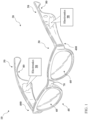
- FIG. 1 is a schematic depiction of a wearable audio device 10 according to various implementations.
- the wearable audio device 10 is a pair of audio eyeglasses 20.
- the wearable audio device 10 includes a frame 30 having a first section (e.g., lens section) 40 and at least one additional section (e.g., arm sections) 50 extending from the first section 40.
- the first (or, lens) section 40 and additional section(s) (arms) 50 are designed for resting on the head of a user.
- the lens section 40 can include a set of lenses 60, which can include prescription, non-prescription and/or light-filtering lenses, as well as a bridge 70 (which may include padding) for resting on the user's nose.
- Arms 50 can include a contour 80 for resting on the user's respective ears.
- electronics 90 and other components for controlling the wearable audio device 10 are Contained within the frame 30 (or substantially contained, such that a component can extend beyond the boundary of the frame) and electronics 90 and other components for controlling the wearable audio device 10 according to particular implementations.
- separate, or duplicate sets of electronics 90 are contained in portions of the frame, e.g., each of the respective arms 50 in the frame 30.
- certain components described herein can also be present in singular form.
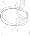
- FIG. 2 depicts another example wearable audio device 10 in the form of headphones 210.
- the headphones 210 include on-ear or around-ear headphones 210.
- the headphones 210 can include a frame 220 with a first section (e.g., headband) 230 and at least one additional section (e.g., earcup(s)) 240 extending from the first section 230.
- the headband 230 includes a head cushion 250.
- electronics 90 and other components for controlling the wearable audio device 10 are stored within one or both of the earcups 240.
- FIG. 3 shows a schematic depiction of the electronics 90 contained within the frame 30 ( FIG. 1 ) and/or the frame 220 ( FIG. 2 ).
- one or more of the components in electronics 90 may be implemented as hardware and/or software, and that such components may be connected by any conventional means (e.g., hard-wired and/or wireless connection).
- any component described as connected or coupled to another component in the wearable audio device 10 or other systems disclosed according to implementations may communicate using any conventional hard-wired connection and/or additional communications protocols.
- separately housed components in wearable audio device 10 are configured to communicate using one or more conventional wireless transceivers.
- electronics 90 contained within the frame 20 can include a transducer 310 (e.g., electro-acoustic transducer), an inertial measurement unit (IMU) 320 (optional, depicted in phantom), and a power source 330.
- the power source 330 is connected to the transducer 310, and can additionally be connected to the IMU 320.
- Each of the transducer 310, IMU 320 and power source 330 are connected with a controller 340, which is configured to perform control functions according to various implementations described herein.
- Electronics 90 can include other components not specifically depicted herein, such as communications components (e.g., a wireless transceiver (WT)) configured to communicate with one or more other electronic devices connected via one or more wireless networks (e.g., a local WiFi network, Bluetooth connection, or radio frequency (RF) connection), and amplification and signal processing components. It is understood that these components or functional equivalents of these components can be connected with, or form part of, the controller 340.
- the electronics 90 can include an interface 350 coupled with the controller 340 for enabling functions such as audio selection, powering on the audio eyeglasses or engaging a voice control function.
- the interface 350 includes a button, a compressible interface and/or a capacitive touch interface.
- the wearable audio device 10 includes a hinge 400 coupling the first section (e.g., lens section 40 in FIG. 1 , or headband 230 in FIG. 2 ) with the additional section(s) (e.g., arms 50 in FIG. 1 , or earcups 240 in FIG. 2 ).
- the wearable audio device 10 includes multiple hinges 400, e.g., between a lens section 40 and each of the arms 50 in the audio eyeglasses 20 ( FIG. 1 ), or between the headband 230 and each of the earcups 240 ( FIG. 2 ).
- a portion of the hinge 400 can be fixed within a slot in the lens section 40.
- the hinge 400 is configured to enable wiring to run therethrough, for example, between sections in the wearable audio device 10.
- one or more portions of the frame 20, as well as the hinge 400 can be formed substantially of a plastic or composite material.
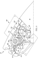
- FIG. 4 a cut-away perspective view of the hinge 400 is shown according to various implementations.
- the hinge 400 is shown joining the lens section 40 with arms 50.
- the hinge 400 is integral with each of the arm(s) 50.
- portions of the hinge 400 are integral with each of the lens section 40 and the arms 50, respectively.
- the hinge 400 is in a substantially open position.
- the hinge 400 can permit movement (e.g., pivoting) of the first section of the wearable audio device 10 ( FIGS.
- FIG. 5 illustrates a different cut-away perspective view of the hinge 400, removing illustration of the hinge mechanism and cable management feature that are present in FIG. 4 .
- FIG. 6 shows the hinge 400 during a preliminary formation process.
- FIG. 7 is a perspective view of a portion of the hinge 400 and the cable 410 where the cable 410 enters the arm 50 of the audio eyeglasses 20 in FIG. 1 .
- the hinge 400 includes a body 420 defining a cavity 430 for accommodating the cable 410.
- the body 420 can be formed of one or more conventional materials used in the eyeglasses industry, such as plastics or composites.
- the cavity 430 is sized to accommodate the cable 410 extending therethrough, i.e., the cavity 430 has a first opening 440 to a pathway 450 (obstructed in these views) in the first section (e.g., lens section 40, FIG. 1 ) and a second opening 460 to an additional pathway 470 (obstructed in these views) in the additional section (e.g., arm section 50, FIG. 1 ).
- the cable 410 includes a flexible printed circuit (FPC) for connecting different components in the electronics 90, and/or connecting electronics 90 in different sections of the wearable audio device 10 ( FIG. 1 , FIG. 2 ).
- FPC flexible printed circuit
- the cable 410 includes an FPC
- that FPC can include a single-layer or multi-layer FPC.
- the cable 410 includes one or more wire(s), or one or more cable(s), which may be packaged in an assembly.
- the cable 410 e.g., FPC, wire(s), and/or cable(s)
- the cable 410 is thinner in a region contained within the hinge 400 than in a distinct region within the pathway 450 or the additional pathway 470.
- thinner section(s) of the cable 410 reside within the hinge 400 than in other sections of the wearable audio device 10.
- the hinge 400 includes an insert 480 located within the body 420 that is adjacent to the second opening 460.
- the insert 480 has an arcuate surface 490 that faces an opposing inner wall 500 of the cavity 430.
- the arcuate surface 490 is a beveled or chamfered edge between approximately perpendicular sides 510, 520 ( FIG. 5 ) of the insert 480.
- the insert 480 defines a minimum radius of a bend 530 ( FIG. 4 , FIG. 6 ) in the cable 410 within the cavity 430.
- the arcuate surface 490 defines the minimum radius of the bend 530 in the cable 410, such that the cable 410 contacts the arcuate surface 490 along approximately an entirety of the length of that surface 490.
- the minimum radius of this bend 530 is defined within the hinge 400. That is, the hinge 400 is overmolded on the cable 410 such that the body 420 surrounds the portion of the cable 410 extending through the cavity 430. Additionally, the body 420 of the hinge 400 is overmolded on the insert 480, such that the body 420 surrounds the insert 480.
- the body 420 includes an overmolded plastic, and the insert 480 is non-unitary with the body 420. That is, the insert 480 and the body 420 are originally formed as separate components.
- the body 420 and/or the insert 480 are formed of a plastic such as polycarbonate, acrylonitrile butadiene styrene, and/or polyamide.
- the insert 480 is more rigid than the body 420, however, this is not necessary in all implementations.
- the insert 480 fits in a slot 540 in the body 420.
- the insert 480 is insert-molded into the body 420, e.g., at the slot 540.
- the hinge 400 further includes one or more adhesive strip(s) 550 that couple the cable 410 to the hinge body 420.
- the hinge 400 includes two distinct adhesive strips 550 coupling the cable 410 to distinct portions of the hinge body 420.
- a first adhesive strip 550 couples the cable 410 to the body 420 proximate the second opening 460, e.g., ahead of the bend 530 when viewed from the second opening 460 into the body 420.
- This first adhesive strip 550A ( FIG. 4 ) can be coupled to a first interior wall 570 of the body 420 that is located adjacent the insert 480.
- a second example adhesive strip 550B is shown coupling the cable 410 to a second interior wall 580 of the body 420 that is located past the bend 530 when viewed from the first opening 440 into the body 420. That is, the adhesive strips 550 couple the cable 410 to the body 420 on both sides of the insert 480. In some cases, the adhesive strips 550 couple the cable 410 to the body 420 on opposite sides of the cable 410.
- FIG. 5 illustrates the cable 410 with adhesive strips 550 and the insert 480 prior to applying the second adhesive strip 550B to the second interior wall 580.
- FIG. 6 illustrates the cable 410 after the second adhesive strip 550B is coupled with the second interior wall 580.
- FIG. 7 shows the cable 410 in isolation with the insert 480 in a portion of the body 420, for example, to illustrate the bend 530.
- the minimum radius of the bend 530 is controlled by the insert 480 within the body 420 of the hinge 400, such that the cable 410 is bent at a defined radius prior to exiting the hinge 400, e.g., at the opening 460.
- This is in contrast to conventional overmolded cable configurations, where poorly defined bending occurs at the entry/exit of the component (e.g., hinge) or in a portion of the device where the cable is exposed. This can cause stress on the cable, as well as expose the cable to unwanted ambient conditions.
- the overmolded cable configuration in the wearable audio devices 10 depicted herein can control the minimum radius of the bend 530 in the cable 410, which in certain implementations, is located within the body of the hinge 400, e.g., prior to exiting the hinge 400.
- the wearable audio device 10 further includes a hinge mechanism 590 contained within the body 420.
- the hinge mechanism 590 includes a spring, a set of interlocking arms or a tension member for enabling controlled movement of the second section (e.g., arm section 50) relative to the first section (e.g., lens section 40). It is understood that the hinge mechanism 590 can include any hinge component(s) that permit controlled rotation of a first section relative to a second section.
- the hinge mechanism 590 includes a spring (e.g., coil spring) 600 with a pair of lever arms 610 for controlling movement of the arm section 50 relative to the lens section 40.
- the spring 600 controls movement around a pin 615 or other pivot point (pin slot 625 shown in FIGS. 5 and 6 ).
- the hinge mechanism 590 has a primary axis (Ap) about which the arm section 50 moves relative to the lens section 40.
- the primary axis (Ap) is the axis about which the lever arms pivot (or, rotate).
- the cable 410 wraps around the hinge mechanism 590 radially outboard relative to the primary axis (Ap).
- the wearable audio device 10 further includes a cable management feature 620 contained within the body 420 of the hinge 400.
- the cable management feature 620 utilizes the pin 615 extending vertically through the hinge 400 about which the cable 410 is routed.
- the cable management feature 620 includes an arm 640 that extends within the cavity 430 and controls movement of the cable 410 as the arm 50 moves relative to lens section 40 (e.g., in the example depiction in FIG. 4 ).
- the arm 640 can include a hook-shaped tab with a first section 650 and a second section 660 extending from the first section 650 at an angle.
- the sections of the arm 640 form an arcuate interface 670 for introducing a second bend 680 in the cable 410.
- the arm (of the audio eyeglasses) 50 moves relative to the lens section 40, the arm (of the cable management feature) 640 contacts a surface of the cable 410 and maintains the second bend 680 in the cable 410.
- the cable management feature 620 remains in contact with the cable 410 throughout approximately an entire range of motion of the hinge 400.
- the hinge mechanism 590, cable management feature 620 and cable 410 are all located in a common plane (P) which is radially oriented relative to the primary axis (Ap) of the hinge mechanism 590, that is, the common plane (P) is perpendicular to the primary axis (Ap).
- a common plane (P) exists that runs perpendicular to the primary axis (Ap) and intersects each of the hinge mechanism 590, cable management feature 620 and cable 410.
- aligning components in a common plane (P) can reduce the footprint of the hinge 400, simplify manufacturing processes for the hinge 400, and/or improve the robustness of the hinge 400.
- FIG. 8 shows an additional implementation of an audio device 10, for example, a pair of audio eyeglasses 800.
- the audio eyeglasses 800 can include a number of common features with the audio eyeglasses 20 depicted and described with reference to FIGS. 1 and 3 . Redundant explanation of these components is omitted.
- the audio eyeglasses 800 depicted in FIG. 8 can include a hinge 805 similarly described with reference to FIGS. 1 and 4-7.
- FIG. 9 shows a cut-away view of a portion of the hinge 805 along with the second (e.g., arm) section 50 from the perspective of the inside of the arm 50.
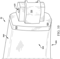
- FIG. 10 shows a portion of the hinge 805 coupled with the arm 50, from the perspective of the outside of the arm 50.
- the hinge 805 includes a hinge mechanism 810 that includes metal ledge 820 separating the first (or, lens) section 40 and each additional section (arm) 50.
- the metal ledge 820 is visible around an entirety of an interface 830 (e.g., vertical interface) between the first section 40 and the additional section 50 while the hinge 805 is in the fully open position.
- the metal ledge 820 is illustrated as visible proximate the outer facing surface 830 as well as the top and bottom surfaces 840, 850 of the arm 50 in FIG. 10 .
- the metal ledge 820 remains stationary and in contact with the arm 50 throughout an entire range of motion of the hinge 805.
- the hinge mechanism 810 is coupled with the arm 50 by a first set of mating features 860.
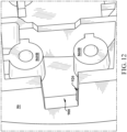
- This first set of mating features 860 are further illustrated in FIGS. 11 and 12 , which show a portion of the arm 50 in isolation.
- Mating features 860 on the hinge mechanism 810 are denoted with an "A”
- mating features on the arm 50 are denoted with a "B”.
- mating feature(s) 860A can include one or more slots
- mating feature(s) 860B can include a protrusion such as a tab, bump or pillar, which in some cases includes a counter-bore for receiving a fastener 870 ( FIG.
- the mating features 860A on the hinge mechanism 810 are sized to receive the mating features 860B on the arm 50, e.g., as a male-female coupling.
- the mating features 860B on the arm 50 include an internal slot or groove 880 for receiving the fastener 870 ( FIG. 13 ).
- the mating features 860A on the hinge mechanism 810 are part of a plate 890 that fits within a slot 900 in the arm 50.
- the plate 890 can include a thinned section 910 extending through, and complementing, the slot 900.
- the hinge 805 additionally includes another set of mating features 920, illustrated in detail in FIGS. 11 and 12 .
- the mating features 920 includes a set of ribs configured to improve the fit of the plate 890 within the recess in the arm 50.
- these mating features 920 e.g., ribs
- these mating features 920 are located along one or more interior surfaces of the arm 50, and in some cases, such as illustrated with mating features 920A, are vertically aligned with mating features 860B on the arm 50.
- a mating feature 920 such as a rib can be located in the slot 900 to contact the thinned section 910.
- the hinge 805 includes a cable management feature 930 located on a distinct side of the slot 900 from the mating features 860A, 860B.
- the cable management feature 930 and the hinge mechanism 810 are unitary and formed of a metal.
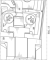
- FIG. 13 shows a close-up perspective view of the hinge 805 including the cable 410.
- the cable management feature 930, hinge mechanism 810 and cable 410 ( FIG. 13 ) in the hinge 805 are all located in a common plane (P).
- the hinge 805 enables smooth, controlled movement of the arm 50 relative to the lens region 40 while obstructing the cable 410 from view. Additionally, the hinge 805 is configured to maintain the position of the metal ledge 820 through the entire range of motion.
- the hinges shown and described can enhance manufacturability, longevity and functionality relative to conventional audio device hinges.
- the hinges shown and described herein mitigate wear on the cable during use of the wearable audio device(s), and enable routing of the cable through the hinge while efficiently using vertical space. This enables a more compact, functional configuration when compared with conventional audio device cable-through hinges.
- components described as being “coupled” to one another can be joined along one or more interfaces.
- these interfaces can include junctions between distinct components, and in other cases, these interfaces can include a solidly and/or integrally formed interconnection. That is, in some cases, components that are “coupled” to one another can be simultaneously formed to define a single continuous member.
- these coupled components can be formed as separate members and be subsequently joined through known processes (e.g., soldering, fastening, ultrasonic welding, bonding).
- electronic components described as being “coupled” can be linked via conventional hard-wired and/or wireless means such that these electronic components can communicate data with one another. Additionally, subcomponents within a given component can be considered to be linked via conventional pathways, which may not necessarily be illustrated.
Landscapes
- Physics & Mathematics (AREA)
- Health & Medical Sciences (AREA)
- Acoustics & Sound (AREA)
- General Physics & Mathematics (AREA)
- Ophthalmology & Optometry (AREA)
- Optics & Photonics (AREA)
- Engineering & Computer Science (AREA)
- Signal Processing (AREA)
- Otolaryngology (AREA)
- General Health & Medical Sciences (AREA)
- Manufacturing & Machinery (AREA)
- Eyeglasses (AREA)
- Headphones And Earphones (AREA)
Claims (14)
- Tragbare Audiovorrichtung (10), umfassend:
einen Rahmen (30) zum Aufliegen auf dem Kopf eines Benutzers, wobei der Rahmen umfasst:einen ersten Abschnitt (40); einen zusätzlichen Abschnitt (50), der sich aus dem ersten Abschnitt erstreckt; ein Scharnier (400), das den ersten Abschnitt und den zusätzlichen Abschnitt verbindet; und ein Kabel (410), das sich durch das Scharnier hindurch erstreckt,wobei das Scharnier auf dem Kabel aufgeformt ist und umfasst:einen Körper (420), der einen Hohlraum (430) definiert, der das Kabel aufnimmt,wobei der Hohlraum eine erste Öffnung (440) zu einem Weg (450) im ersten Abschnitt, und eine zweite Öffnung (460) zu einem zusätzlichen Weg (470) im zusätzlichen Abschnitt aufweist;einen Einsatz (480) innerhalb des Körpers und an die zweite Öffnung angrenzend, wobei der Einsatz einen Mindestradius einer ersten Biegung (530) im Kabel innerhalb des Hohlraumes definiert;einen im Körper enthaltenen Scharniermechanismus (590), wobei der Scharniermechanismus eine Feder (600), einen Satz von Verriegelungsarmen (610) oder ein Zugelement zum Ermöglichen einer kontrollierten Bewegung des zusätzlichen Abschnitts in Bezug zum ersten Abschnitt beinhaltet; undein Kabelverwaltungsmerkmal (620), das innerhalb des Körpers enthalten ist, wobei das Kabelverwaltungsmerkmal einen Arm (640) beinhaltet, der angeordnet ist, um sich innerhalb des Hohlraums zu erstrecken, und um die Bewegung des Kabels zu kontrollieren, wenn sich der zusätzliche Abschnitt in Bezug zum ersten Abschnitt bewegt,wobei sich der Scharniermechanismus, das Kabelverwaltungsmerkmal und das Kabel allesamt in einer gemeinsamen Ebene (P) befinden, die in Bezug zu einer Primärachse (Ap) des Scharniermechanismus radial ausgerichtet ist. - Tragbare Audiovorrichtung (10) nach Anspruch 1, wobei die tragbare Audiovorrichtung Audiobrillen (20) umfasst, wobei der erste Abschnitt einen Linsenbereich umfasst, der zusätzliche Abschnitt einen Arm umfasst und das Scharnier den Linsenbereich mit dem Arm koppelt, und wobei ein Abschnitt des Scharniers innerhalb eines Schlitzes im Linsenbereich fixiert ist.
- Tragbare Audiovorrichtung (10) nach Anspruch 1, wobei die tragbare Audiovorrichtung ein Headset umfasst, wobei der erste Abschnitt ein Stirnband umfasst, der zusätzliche Abschnitt einen Ohrhörer umfasst und das Scharnier das Stirnband mit dem Ohrhörer koppelt.
- Tragbare Audiovorrichtung (10) nach Anspruch 1, weiter umfassend:einen elektroakustischen Wandler, der zumindest teilweise im Rahmen eingehaust ist,und eine schallabstrahlende Oberfläche zur Bereitstellung einer Audioausgabe umfasst.
- Tragbare Audiovorrichtung (10) nach Anspruch 1, wobei das Scharnier eine Bewegung des zusätzlichen Abschnitts in Bezug zum ersten Abschnitt erlaubt.
- Tragbare Audiovorrichtung (10) nach Anspruch 1, die weiter zumindest ein Mikrofon im ersten Abschnitt oder dem zusätzlichen Abschnitt umfasst.
- Tragbare Audiovorrichtung (10) nach Anspruch 1, wobei das Kabel eine flexible gedruckte Leiterplatte (FPC) umfasst, und wobei die FPC in einem Bereich, der innerhalb des Scharniers enthalten ist, dünner ist als in einem unterschiedlichen Bereich innerhalb des Weges oder des zusätzlichen Weges.
- Tragbare Audiovorrichtung (10) nach Anspruch 1, wobei der Körper des Scharniers einen aufgeformten Kunststoff umfasst, wobei der Einsatz nicht in einem Stück mit dem Körper ist, und wobei der aufgeformte Körper des Scharniers den Einsatz einhüllt.
- Tragbare Audiovorrichtung (10) nach Anspruch 1, wobei sich das Kabel um den Scharniermechanismus radial nach außen in Bezug zur Primärachse des Scharniermechanismus wickelt, um die sich der zusätzliche Abschnitt in Bezug zum ersten Abschnitt bewegt.
- Tragbare Audiovorrichtung (10) nach Anspruch 1, wobei das Scharnier eine Metallleiste umfasst, die den ersten Abschnitt und den zusätzlichen Abschnitt trennt, wobei die Metallleiste um eine Gesamtheit einer Schnittstelle zwischen dem ersten Abschnitt und dem zusätzlichen Abschnitt sichtbar ist, während sich das Scharnier in einer vollständig geöffneten Position befindet.
- Tragbare Audiovorrichtung (10) nach Anspruch 10, wobei das Kabelverwaltungsmerkmal und der Scharniermechanismus in einem Stück und aus einem Metall gebildet sind, und wobei das Scharnier einen Satz von Passmerkmalen beinhaltet, die mit einem komplementären Satz von Passmerkmalen im zusätzlichen Abschnitt gekoppelt sind.
- Tragbare Audiovorrichtung (10) nach Anspruch 1, wobei der Arm des Kabelverwaltungsmerkmals eine hakenförmige Lasche mit einem ersten Armabschnitt (650) und einem zweiten Armabschnitt (660) beinhaltet, der sich in einem Winkel aus dem ersten Armabschnitt erstreckt.
- Tragbare Audiovorrichtung (10) nach Anspruch 12, wobei der erste und zweite Armabschnitt eine Bogenschnittstelle (670) zum Einleiten einer zweiten Biegung (680) in dem Kabel bilden.
- Tragbare Audiovorrichtung (10) nach Anspruch 1, wobei der Einsatz zum Kontrollieren des Mindestradius der ersten Biegung innerhalb des Körpers angeordnet ist, sodass das Kabel in einem definierten Radius gebogen wird, bevor es das Scharnier an der zweiten Öffnung verlässt.
Applications Claiming Priority (3)
| Application Number | Priority Date | Filing Date | Title |
|---|---|---|---|
| US16/778,132 US11662609B2 (en) | 2020-01-31 | 2020-01-31 | Wearable audio device with cable-through hinge |
| US16/851,730 US11513366B2 (en) | 2020-01-31 | 2020-04-17 | Audio eyeglasses with double-detent hinge |
| PCT/US2021/015399 WO2021154928A1 (en) | 2020-01-31 | 2021-01-28 | Wearable audio device with cable-through hinge |
Publications (2)
| Publication Number | Publication Date |
|---|---|
| EP4097989A1 EP4097989A1 (de) | 2022-12-07 |
| EP4097989B1 true EP4097989B1 (de) | 2025-04-16 |
Family
ID=74669568
Family Applications (1)
| Application Number | Title | Priority Date | Filing Date |
|---|---|---|---|
| EP21706801.4A Active EP4097989B1 (de) | 2020-01-31 | 2021-01-28 | Tragbares audiogerät mit kabeldurchgangsscharnier |
Country Status (4)
| Country | Link |
|---|---|
| US (1) | US11513366B2 (de) |
| EP (1) | EP4097989B1 (de) |
| CN (1) | CN115211140B (de) |
| WO (1) | WO2021154928A1 (de) |
Families Citing this family (10)
| Publication number | Priority date | Publication date | Assignee | Title |
|---|---|---|---|---|
| US11880093B2 (en) | 2020-02-18 | 2024-01-23 | Snap Inc. | Hyperextending hinge for wearable electronic device |
| US11378817B2 (en) | 2020-02-18 | 2022-07-05 | Snap Inc. | Hyperextending hinge having FPC service loops for eyewear |
| US11543679B2 (en) | 2020-02-18 | 2023-01-03 | Snap Inc. | Hyperextending hinge having cosmetic trim for eyewear |
| USD1017671S1 (en) * | 2020-11-20 | 2024-03-12 | Bose Corporation | Audio eyeglasses |
| USD1016895S1 (en) * | 2020-11-20 | 2024-03-05 | Bose Corporation | Eyeglasses |
| USD1048155S1 (en) * | 2020-11-20 | 2024-10-22 | Bose Corporation | Eyeglasses |
| EP4266701A4 (de) * | 2022-01-27 | 2024-07-17 | Shenzhen Shokz Co., Ltd. | Wearable-vorrichtung und verschleissteil davon |
| CN117769673A (zh) * | 2022-01-27 | 2024-03-26 | 深圳市韶音科技有限公司 | 佩戴件、可穿戴设备及充电系统 |
| FR3133454B1 (fr) | 2022-03-10 | 2025-06-20 | Ideatechnic S A R L | Système de charnière pour monture de lunettes et lunettes comportant un tel système de charnière |
| US20250085568A1 (en) * | 2023-09-08 | 2025-03-13 | Innovative Eyewear, Inc. | Spring-loaded hinges for smartglasses |
Family Cites Families (36)
| Publication number | Priority date | Publication date | Assignee | Title |
|---|---|---|---|---|
| CA2059597A1 (en) * | 1991-01-22 | 1992-07-23 | Paul A. Vogt | Radio eyewear |
| FR2703477A1 (fr) | 1993-03-30 | 1994-10-07 | Piard Gerard | Charnière, notamment pour monture de lunettes. |
| US7310072B2 (en) * | 1993-10-22 | 2007-12-18 | Kopin Corporation | Portable communication display device |
| JP2975361B1 (ja) | 1998-11-10 | 1999-11-10 | 株式会社タケダ企画 | 眼鏡用のバネ蝶番 |
| US6769767B2 (en) * | 2001-04-30 | 2004-08-03 | Qr Spex, Inc. | Eyewear with exchangeable temples housing a transceiver forming ad hoc networks with other devices |
| US7760898B2 (en) * | 2003-10-09 | 2010-07-20 | Ip Venture, Inc. | Eyeglasses with hearing enhanced and other audio signal-generating capabilities |
| US8778022B2 (en) * | 2004-11-02 | 2014-07-15 | E-Vision Smart Optics Inc. | Electro-active intraocular lenses |
| WO2007037089A1 (ja) * | 2005-09-27 | 2007-04-05 | Konica Minolta Holdings, Inc. | 頭部装着型映像表示装置 |
| KR100704494B1 (ko) * | 2005-11-30 | 2007-04-09 | 주식회사 에이텍옵티컬 | 안경용 스프링 힌지 |
| US20070248238A1 (en) * | 2005-12-13 | 2007-10-25 | Abreu Marcio M | Biologically fit wearable electronics apparatus and methods |
| TW200804887A (en) | 2006-07-12 | 2008-01-16 | Jia-Lin Jou | Slim frame of spectacle having electronic device thereon, and spectacle having the same |
| US8905541B2 (en) | 2010-07-02 | 2014-12-09 | Mitsui Chemicals, Inc. | Electronic spectacle frames |
| US8801174B2 (en) * | 2011-02-11 | 2014-08-12 | Hpo Assets Llc | Electronic frames comprising electrical conductors |
| US20100045928A1 (en) * | 2008-08-25 | 2010-02-25 | Tri-Specs, Inc. | Fashion eyewear frame that houses circuitry to effect wireless audio communication while providing extraneous background noise cancellation capability |
| WO2010062481A1 (en) * | 2008-11-02 | 2010-06-03 | David Chaum | Near to eye display system and appliance |
| BRPI1007206A2 (pt) * | 2009-01-09 | 2016-02-23 | Pixeloptics Inc | óculos eletroa-ativo e eletrônica associada |
| CN201673332U (zh) | 2010-05-24 | 2010-12-15 | 励金友 | 眼镜 |
| US9075249B2 (en) * | 2012-03-07 | 2015-07-07 | Google Inc. | Eyeglass frame with input and output functionality |
| US10423011B2 (en) * | 2012-06-14 | 2019-09-24 | Mitsui Chemicals, Inc. | Lens, lens blank, and eyewear |
| US9442305B2 (en) | 2012-06-14 | 2016-09-13 | Mitsui Chemicals, Inc. | Electronic eyeglasses and methods of manufacturing |
| US9609415B2 (en) * | 2014-03-26 | 2017-03-28 | Bose Corporation | Headphones with cable management |
| KR101760013B1 (ko) * | 2014-08-13 | 2017-07-31 | 엘지전자 주식회사 | 전자 디바이스 및 그 제어방법 |
| US9703119B2 (en) * | 2014-08-13 | 2017-07-11 | Google Inc. | Compact folding architecture for head mounted device |
| JP6513195B2 (ja) * | 2015-06-01 | 2019-05-15 | アルプスアルパイン株式会社 | 眼鏡型電子機器 |
| WO2016194849A1 (ja) * | 2015-06-01 | 2016-12-08 | アルプス電気株式会社 | 眼鏡型電子機器 |
| US10859853B2 (en) * | 2015-09-24 | 2020-12-08 | Essilor International | Electronic frames |
| US10761346B1 (en) * | 2015-12-28 | 2020-09-01 | Amazon Technologies, Inc. | Head-mounted computer device with hinge |
| US9794676B2 (en) | 2016-01-12 | 2017-10-17 | Bose Corporation | Headphone |
| US9851585B2 (en) * | 2016-02-29 | 2017-12-26 | Snap Inc. | Heat sink configuration for wearable electronic device |
| US10168555B1 (en) * | 2016-06-30 | 2019-01-01 | Google Llc | Wiring in a head-mountable device |
| US20180041827A1 (en) * | 2016-08-05 | 2018-02-08 | The Ketchum Group, Inc., Dba, Outdoor Technology | Headphone housing assembly |
| SE540628C2 (en) * | 2016-11-01 | 2018-10-09 | Skugga Tech Ab | Hinge between a frame and a temple of spectacles |
| US10852562B2 (en) * | 2017-10-31 | 2020-12-01 | Snap Inc. | Conductive connection through eyewear hinge |
| US10353221B1 (en) | 2018-07-31 | 2019-07-16 | Bose Corporation | Audio eyeglasses with cable-through hinge and related flexible printed circuit |
| US11474376B2 (en) * | 2018-12-02 | 2022-10-18 | Vigo Technologies, Inc. | Hinge designs in wearable electronic devices |
| US11662609B2 (en) * | 2020-01-31 | 2023-05-30 | Bose Corporation | Wearable audio device with cable-through hinge |
-
2020
- 2020-04-17 US US16/851,730 patent/US11513366B2/en active Active
-
2021
- 2021-01-28 EP EP21706801.4A patent/EP4097989B1/de active Active
- 2021-01-28 CN CN202180017116.4A patent/CN115211140B/zh active Active
- 2021-01-28 WO PCT/US2021/015399 patent/WO2021154928A1/en not_active Ceased
Also Published As
| Publication number | Publication date |
|---|---|
| CN115211140A (zh) | 2022-10-18 |
| US11513366B2 (en) | 2022-11-29 |
| US20210240007A1 (en) | 2021-08-05 |
| EP4097989A1 (de) | 2022-12-07 |
| WO2021154928A1 (en) | 2021-08-05 |
| CN115211140B (zh) | 2025-11-21 |
Similar Documents
| Publication | Publication Date | Title |
|---|---|---|
| US11513366B2 (en) | Audio eyeglasses with double-detent hinge | |
| EP3830634B1 (de) | Audiobrille mit scharnier mit kabeldurchgang und zugehörige flexible leiterplatte | |
| US11662609B2 (en) | Wearable audio device with cable-through hinge | |
| EP4081854A1 (de) | Audio-brille mit zweiflügeligem scharnier | |
| JP6941651B2 (ja) | ワイヤ状アタッチメント機構を介した結合用イヤチップ | |
| US10129630B2 (en) | Floating-cup pivot for head-worn audio devices | |
| US10582292B2 (en) | Printed circuit board (PCB) mount for headphone earcup | |
| WO2020038482A1 (zh) | 一种眼镜 | |
| US20230254622A1 (en) | Wearable audio device with modular component attachment | |
| US10085084B2 (en) | Wearable device with sound sealing structure | |
| JP2023519015A (ja) | 電子機器 | |
| WO2012120295A1 (en) | Audio apparatus | |
| US20250344008A1 (en) | Audio Headset with Removably Coupled Earphones | |
| EP4176588A1 (de) | Audiovorrichtung mit flexibler schaltung für kapazitive schnittstelle | |
| CN120113253A (zh) | 机芯模组及耳机 | |
| US20240179462A1 (en) | Audio device with electrostatic discharge protection | |
| US20250254454A1 (en) | Audio headset with removably coupled earphones | |
| EP2230859B1 (de) | Ohrstück | |
| WO2013073101A1 (ja) | 携帯端末、ケーブル、および、積層シートの製造方法 | |
| US20260129378A1 (en) | Bone conduction hearing aid devices | |
| EP4683344A1 (de) | Ohrhörer | |
| JP2026500360A (ja) | 静電気放電戻り止めばねを備えた電子デバイス | |
| WO2020217907A1 (ja) | 撮像装置およびアクセサリ |
Legal Events
| Date | Code | Title | Description |
|---|---|---|---|
| STAA | Information on the status of an ep patent application or granted ep patent |
Free format text: STATUS: UNKNOWN |
|
| STAA | Information on the status of an ep patent application or granted ep patent |
Free format text: STATUS: THE INTERNATIONAL PUBLICATION HAS BEEN MADE |
|
| PUAI | Public reference made under article 153(3) epc to a published international application that has entered the european phase |
Free format text: ORIGINAL CODE: 0009012 |
|
| STAA | Information on the status of an ep patent application or granted ep patent |
Free format text: STATUS: REQUEST FOR EXAMINATION WAS MADE |
|
| 17P | Request for examination filed |
Effective date: 20220725 |
|
| AK | Designated contracting states |
Kind code of ref document: A1 Designated state(s): AL AT BE BG CH CY CZ DE DK EE ES FI FR GB GR HR HU IE IS IT LI LT LU LV MC MK MT NL NO PL PT RO RS SE SI SK SM TR |
|
| DAV | Request for validation of the european patent (deleted) | ||
| DAX | Request for extension of the european patent (deleted) | ||
| GRAP | Despatch of communication of intention to grant a patent |
Free format text: ORIGINAL CODE: EPIDOSNIGR1 |
|
| STAA | Information on the status of an ep patent application or granted ep patent |
Free format text: STATUS: GRANT OF PATENT IS INTENDED |
|
| RIC1 | Information provided on ipc code assigned before grant |
Ipc: G02C 11/06 20060101ALI20241212BHEP Ipc: G02C 5/22 20060101ALI20241212BHEP Ipc: H04R 5/033 20060101ALI20241212BHEP Ipc: H04R 1/10 20060101AFI20241212BHEP |
|
| INTG | Intention to grant announced |
Effective date: 20241220 |
|
| GRAS | Grant fee paid |
Free format text: ORIGINAL CODE: EPIDOSNIGR3 |
|
| GRAA | (expected) grant |
Free format text: ORIGINAL CODE: 0009210 |
|
| STAA | Information on the status of an ep patent application or granted ep patent |
Free format text: STATUS: THE PATENT HAS BEEN GRANTED |
|
| AK | Designated contracting states |
Kind code of ref document: B1 Designated state(s): AL AT BE BG CH CY CZ DE DK EE ES FI FR GB GR HR HU IE IS IT LI LT LU LV MC MK MT NL NO PL PT RO RS SE SI SK SM TR |
|
| REG | Reference to a national code |
Ref country code: GB Ref legal event code: FG4D |
|
| REG | Reference to a national code |
Ref country code: CH Ref legal event code: EP Ref country code: DE Ref legal event code: R096 Ref document number: 602021029198 Country of ref document: DE |
|
| REG | Reference to a national code |
Ref country code: IE Ref legal event code: FG4D |
|
| REG | Reference to a national code |
Ref country code: NL Ref legal event code: MP Effective date: 20250416 |
|
| PG25 | Lapsed in a contracting state [announced via postgrant information from national office to epo] |
Ref country code: NL Free format text: LAPSE BECAUSE OF FAILURE TO SUBMIT A TRANSLATION OF THE DESCRIPTION OR TO PAY THE FEE WITHIN THE PRESCRIBED TIME-LIMIT Effective date: 20250416 |
|
| REG | Reference to a national code |
Ref country code: AT Ref legal event code: MK05 Ref document number: 1786672 Country of ref document: AT Kind code of ref document: T Effective date: 20250416 |
|
| PG25 | Lapsed in a contracting state [announced via postgrant information from national office to epo] |
Ref country code: FI Free format text: LAPSE BECAUSE OF FAILURE TO SUBMIT A TRANSLATION OF THE DESCRIPTION OR TO PAY THE FEE WITHIN THE PRESCRIBED TIME-LIMIT Effective date: 20250416 Ref country code: PT Free format text: LAPSE BECAUSE OF FAILURE TO SUBMIT A TRANSLATION OF THE DESCRIPTION OR TO PAY THE FEE WITHIN THE PRESCRIBED TIME-LIMIT Effective date: 20250818 Ref country code: ES Free format text: LAPSE BECAUSE OF FAILURE TO SUBMIT A TRANSLATION OF THE DESCRIPTION OR TO PAY THE FEE WITHIN THE PRESCRIBED TIME-LIMIT Effective date: 20250416 |
|
| REG | Reference to a national code |
Ref country code: LT Ref legal event code: MG9D |
|
| PG25 | Lapsed in a contracting state [announced via postgrant information from national office to epo] |
Ref country code: GR Free format text: LAPSE BECAUSE OF FAILURE TO SUBMIT A TRANSLATION OF THE DESCRIPTION OR TO PAY THE FEE WITHIN THE PRESCRIBED TIME-LIMIT Effective date: 20250717 Ref country code: NO Free format text: LAPSE BECAUSE OF FAILURE TO SUBMIT A TRANSLATION OF THE DESCRIPTION OR TO PAY THE FEE WITHIN THE PRESCRIBED TIME-LIMIT Effective date: 20250716 |
|
| PG25 | Lapsed in a contracting state [announced via postgrant information from national office to epo] |
Ref country code: PL Free format text: LAPSE BECAUSE OF FAILURE TO SUBMIT A TRANSLATION OF THE DESCRIPTION OR TO PAY THE FEE WITHIN THE PRESCRIBED TIME-LIMIT Effective date: 20250416 |
|
| PG25 | Lapsed in a contracting state [announced via postgrant information from national office to epo] |
Ref country code: BG Free format text: LAPSE BECAUSE OF FAILURE TO SUBMIT A TRANSLATION OF THE DESCRIPTION OR TO PAY THE FEE WITHIN THE PRESCRIBED TIME-LIMIT Effective date: 20250416 |
|
| PG25 | Lapsed in a contracting state [announced via postgrant information from national office to epo] |
Ref country code: HR Free format text: LAPSE BECAUSE OF FAILURE TO SUBMIT A TRANSLATION OF THE DESCRIPTION OR TO PAY THE FEE WITHIN THE PRESCRIBED TIME-LIMIT Effective date: 20250416 |
|
| PG25 | Lapsed in a contracting state [announced via postgrant information from national office to epo] |
Ref country code: AT Free format text: LAPSE BECAUSE OF FAILURE TO SUBMIT A TRANSLATION OF THE DESCRIPTION OR TO PAY THE FEE WITHIN THE PRESCRIBED TIME-LIMIT Effective date: 20250416 |
|
| PG25 | Lapsed in a contracting state [announced via postgrant information from national office to epo] |
Ref country code: RS Free format text: LAPSE BECAUSE OF FAILURE TO SUBMIT A TRANSLATION OF THE DESCRIPTION OR TO PAY THE FEE WITHIN THE PRESCRIBED TIME-LIMIT Effective date: 20250716 |
|
| PG25 | Lapsed in a contracting state [announced via postgrant information from national office to epo] |
Ref country code: IS Free format text: LAPSE BECAUSE OF FAILURE TO SUBMIT A TRANSLATION OF THE DESCRIPTION OR TO PAY THE FEE WITHIN THE PRESCRIBED TIME-LIMIT Effective date: 20250816 |
|
| PG25 | Lapsed in a contracting state [announced via postgrant information from national office to epo] |
Ref country code: LV Free format text: LAPSE BECAUSE OF FAILURE TO SUBMIT A TRANSLATION OF THE DESCRIPTION OR TO PAY THE FEE WITHIN THE PRESCRIBED TIME-LIMIT Effective date: 20250416 |
|
| PGFP | Annual fee paid to national office [announced via postgrant information from national office to epo] |
Ref country code: GB Payment date: 20251219 Year of fee payment: 6 |
|
| PG25 | Lapsed in a contracting state [announced via postgrant information from national office to epo] |
Ref country code: DK Free format text: LAPSE BECAUSE OF FAILURE TO SUBMIT A TRANSLATION OF THE DESCRIPTION OR TO PAY THE FEE WITHIN THE PRESCRIBED TIME-LIMIT Effective date: 20250416 Ref country code: SM Free format text: LAPSE BECAUSE OF FAILURE TO SUBMIT A TRANSLATION OF THE DESCRIPTION OR TO PAY THE FEE WITHIN THE PRESCRIBED TIME-LIMIT Effective date: 20250416 |
|
| PGFP | Annual fee paid to national office [announced via postgrant information from national office to epo] |
Ref country code: FR Payment date: 20251217 Year of fee payment: 6 |
|
| REG | Reference to a national code |
Ref country code: DE Ref legal event code: R097 Ref document number: 602021029198 Country of ref document: DE |
|
| PG25 | Lapsed in a contracting state [announced via postgrant information from national office to epo] |
Ref country code: CZ Free format text: LAPSE BECAUSE OF FAILURE TO SUBMIT A TRANSLATION OF THE DESCRIPTION OR TO PAY THE FEE WITHIN THE PRESCRIBED TIME-LIMIT Effective date: 20250416 |
|
| PG25 | Lapsed in a contracting state [announced via postgrant information from national office to epo] |
Ref country code: EE Free format text: LAPSE BECAUSE OF FAILURE TO SUBMIT A TRANSLATION OF THE DESCRIPTION OR TO PAY THE FEE WITHIN THE PRESCRIBED TIME-LIMIT Effective date: 20250416 |
|
| PG25 | Lapsed in a contracting state [announced via postgrant information from national office to epo] |
Ref country code: SK Free format text: LAPSE BECAUSE OF FAILURE TO SUBMIT A TRANSLATION OF THE DESCRIPTION OR TO PAY THE FEE WITHIN THE PRESCRIBED TIME-LIMIT Effective date: 20250416 |
|
| PG25 | Lapsed in a contracting state [announced via postgrant information from national office to epo] |
Ref country code: IT Free format text: LAPSE BECAUSE OF FAILURE TO SUBMIT A TRANSLATION OF THE DESCRIPTION OR TO PAY THE FEE WITHIN THE PRESCRIBED TIME-LIMIT Effective date: 20250416 |
|
| PLBE | No opposition filed within time limit |
Free format text: ORIGINAL CODE: 0009261 |
|
| STAA | Information on the status of an ep patent application or granted ep patent |
Free format text: STATUS: NO OPPOSITION FILED WITHIN TIME LIMIT |
|
| REG | Reference to a national code |
Ref country code: CH Ref legal event code: L10 Free format text: ST27 STATUS EVENT CODE: U-0-0-L10-L00 (AS PROVIDED BY THE NATIONAL OFFICE) Effective date: 20260225 |
|
| 26N | No opposition filed |
Effective date: 20260119 |
|
| PGFP | Annual fee paid to national office [announced via postgrant information from national office to epo] |
Ref country code: DE Payment date: 20251217 Year of fee payment: 6 |