EP4096870B1 - Outil électrique conçu pour effectuer des opérations de serrage au cours desquelles un couple est fourni en impulsions - Google Patents
Outil électrique conçu pour effectuer des opérations de serrage au cours desquelles un couple est fourni en impulsions Download PDFInfo
- Publication number
- EP4096870B1 EP4096870B1 EP21700864.8A EP21700864A EP4096870B1 EP 4096870 B1 EP4096870 B1 EP 4096870B1 EP 21700864 A EP21700864 A EP 21700864A EP 4096870 B1 EP4096870 B1 EP 4096870B1
- Authority
- EP
- European Patent Office
- Prior art keywords
- power level
- torque
- pulses
- electric motor
- output shaft
- Prior art date
- Legal status (The legal status is an assumption and is not a legal conclusion. Google has not performed a legal analysis and makes no representation as to the accuracy of the status listed.)
- Active
Links
- 238000000034 method Methods 0.000 claims description 10
- 230000008878 coupling Effects 0.000 claims description 5
- 238000010168 coupling process Methods 0.000 claims description 5
- 238000005859 coupling reaction Methods 0.000 claims description 5
- 238000004590 computer program Methods 0.000 description 6
- 230000006870 function Effects 0.000 description 2
- 230000001133 acceleration Effects 0.000 description 1
- GINJFDRNADDBIN-FXQIFTODSA-N bilanafos Chemical compound OC(=O)[C@H](C)NC(=O)[C@H](C)NC(=O)[C@@H](N)CCP(C)(O)=O GINJFDRNADDBIN-FXQIFTODSA-N 0.000 description 1
- 230000007423 decrease Effects 0.000 description 1
- 238000010586 diagram Methods 0.000 description 1
- 230000003287 optical effect Effects 0.000 description 1
- 230000002085 persistent effect Effects 0.000 description 1
- 239000007787 solid Substances 0.000 description 1
Images


Classifications
-
- B—PERFORMING OPERATIONS; TRANSPORTING
- B25—HAND TOOLS; PORTABLE POWER-DRIVEN TOOLS; MANIPULATORS
- B25B—TOOLS OR BENCH DEVICES NOT OTHERWISE PROVIDED FOR, FOR FASTENING, CONNECTING, DISENGAGING OR HOLDING
- B25B21/00—Portable power-driven screw or nut setting or loosening tools; Attachments for drilling apparatus serving the same purpose
- B25B21/02—Portable power-driven screw or nut setting or loosening tools; Attachments for drilling apparatus serving the same purpose with means for imparting impact to screwdriver blade or nut socket
-
- B—PERFORMING OPERATIONS; TRANSPORTING
- B25—HAND TOOLS; PORTABLE POWER-DRIVEN TOOLS; MANIPULATORS
- B25B—TOOLS OR BENCH DEVICES NOT OTHERWISE PROVIDED FOR, FOR FASTENING, CONNECTING, DISENGAGING OR HOLDING
- B25B23/00—Details of, or accessories for, spanners, wrenches, screwdrivers
- B25B23/14—Arrangement of torque limiters or torque indicators in wrenches or screwdrivers
- B25B23/147—Arrangement of torque limiters or torque indicators in wrenches or screwdrivers specially adapted for electrically operated wrenches or screwdrivers
- B25B23/1475—Arrangement of torque limiters or torque indicators in wrenches or screwdrivers specially adapted for electrically operated wrenches or screwdrivers for impact wrenches or screwdrivers
Definitions
- the invention relates to an electric tool adapted to perform tightening operations where torque is delivered in pulses and a method for controlling an electric tool.
- the electric tool In order to achieve an accurate and rapid tightening the electric tool has to use the correct amount of power to achieve both a correct and rapid tightening. It is often hard to set the optimal amount of power, since accuracy and speed often are opposite conditions. If for instance a rapid tightening is desired there is a risk that the joint is tightened to hard. If an accurate tightening is desired the speed to complete the tightening is often low.
- An object of the present disclosure is to provide an electric tool that both can tighten joints rapidly and to the correct target value.
- pulses are created by applying a fixed current during a fixed time to a motor in the electric tool.
- the pulses will have the same power during the entire tightening.
- One object of the present disclosure is to solve or at least mitigate the problem with optimized power of pulses during a tightening.
- the electric power tool provides an inventive solution to the concerns described above by allowing a user of the power tool to set different power levels to be used during different stages of the tightening.
- the user can adjust the power level to for instance be high in the beginning of a tightening up to a certain torque threshold. And set the power level to a lower value above a certain torque threshold, so that the tightening is performed with a lower power close to the target torque.
- the first and second power level parameters p1 and p2 are expressed as percentage of the maximum power level.
- Herby the power can be easily be adjusted to for instance the target torque or any other target value such that the power is reduced in case the torque is close to the target torque. And the power can easily be increased in case the torque is far from the target torque or any other torque value. Thus ensuring the target does not reach above the target torque.
- the pulses can also be set to the user's desire of which type of tightening that is desired. A faster less accurate tightening or a slower more accurate tightening.
- the pulses are provided by a hydraulic pulse unit coupled to the electric motor, the hydraulic pulse unit intermittently couples the electric motor via a hydraulic coupling mechanism to the output shaft.
- the idea according to the present disclosure can be used in an electric tool comprising a hydraulic pulse unit. Thereby providing the possibility to set the power of pulses during a tightening with an electric hydraulic pulse tool. An advantage is optimized power level during whole tightening.
- the speed of the electric motor is controlled so that the electric motor is driven in a pulsed manner to provide pulses on the output shaft.
- the pulses are provided by acceleration the motor within the inherent play that exist in the gearbox between the motor and the output axel.
- the motor is accelerated within a certain play unit that is provided between the motor and the output axel.
- rotational energy is built up in the tool. This rotational energy is then transferred to the screw as a torque pulse, when the play between the motor and the output axle is closed.
- the disclosure relates to a method according to claim 3.
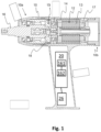
- Fig. 1 depicts an exemplary embodiment of an electric tool 10 in accordance with an embodiment of the present disclosure.
- the electric tool 10 further comprising a front end 10a and a back end 10b.
- the electric tool 10 further comprises a motor 12.
- the motor 12 comprising a rotor 14 that is arranged to rotate with respect to a stator 13.
- An output shaft 16 is arranged at the front end 10a of the housing 10.
- the electric tool 10, according to the illustrated embodiment, further comprises a hydraulic pulse unit 15 which is coupled to the electric motor 12.
- the hydraulic pulse unit 15 intermittently couples the inertia drive member 18 via a hydraulic coupling mechanism to the output shaft 16.
- the function of a hydraulic pulse unit 15 is well known to a person skilled in the art and is not described in detail in this application. A more detailed description of the function of a pulse unit is described in the international patent application WO 91/14541 .
- the electric tool 10 further comprise a processor 20 arranged to control the electric motor 12.
- the electric tool 10 also comprises a memory 26 containing instructions executable by the processor 20.
- the inventor has realised that higher accuracy and faster tightening can be achieved by allowing the user to set the power of the pulses for different stages of the tightening.
- one aspect of the present disclosure relates to an electric tool where the memory 26 containing instructions which when run in the electrical pulse tool causes the electrical tool to control the speed of the electric motor 12, so that the electric tool 10 provide torque pulses on the output shaft 16 with the first power level p1 until the torque threshold is reached.
- the electric tool comprises an angle sensor (not shown) arranged to determine the position of the motor 12.
- the angle sensor is positioned between the motor 12 and the inertia drive member 18. The angle senor can however be located on other places in the electric tool.
- the power of the pulses are determined by providing a current to the electric motor 12 during a predetermined time interval.
- the power of the pulses are provided by providing a current to the electric motor 12 during a predetermined time interval and at the same time monitor the speed of the motor 12.
- a certain determined power can be achieved. If a desired power is not reached at a certain angle of the motor 12, a new current pulse can be provided to the motor 12. This in order to make sure that the desired power of the motor is obtained at the moment the motor 12 couples to the output shaft 16.
- the power is constantly measures and the current feed is controlled so that the power is reached at the moment the inertia drive member 18 couples to the output shaft 16 and the pulse is provided to the screw being tightened.
- the power of the motor 12 is controlled by continuously monitor the actual position of the motor 12 and take the position into account when determining the power.
- the processor 20 is a Central Processing Unit, CPU, microcontroller, Digital Signal Processor, DSP, or any other suitable type of processor capable of executing computer program code.
- the memory 26 is a Random Access Memory, RAM, a Read Only Memory, ROM, or a persistent storage, e.g. a single or combination of magnetic memory, optical memory, or solid state memory or even remotely mounted memory.
- the disclosure further relates to the above mentioned computer program, comprising computer readable code which, when run on the electric tool causes the electric tool to perform any of the aspects of the disclosure described herein.
- the processor 20 comprises one or several of:
- the control modules 161 and 162 are implemented in hardware or in software or in a combination thereof.
- the modules 161 and 162 are according to one aspect implemented as a computer program stored in the memory 26 which run on the processor 20.
- the electric tool is further configured to implement all the aspects of the disclosure as described herein.
- FIG 2 shows one example of a number of pulses in a tightening performed by the electric tool 1 according to the present disclosure.
- Figure 2 comprises three graphs. The graph at the top illustrates the power of the pulses. The graph in the middle illustrates the target torque for the tightening. And the graph at the bottom illustrates the torque t (pulse torque) of the pulses n. As can be seen in the top graph of figure 2 , the power of the pulses vary during the tightening.
- the electric tool provides torque pulses on the output shaft 16 with the first power level p1, since the torque threshold has not been reached.
- the power level of the pulses increases since the torque threshold has been reaches and the user has set the power level to a higher value after the torque threshold.
- the power of the pulses decreases since the user has set the power of the pulses to an even lower value in order to reach the target torque with good accuracy.
- the electric tool is operative to repeat the pulses until a parameter value associated with the tightening of a screw joint has been reached.
- the parameter value associated with the tightening of a screw joint is torque.
- the parameter value associated with the tightening of a screw joint is angle.
- the present disclosure also relates to a computer-readable storage medium, having stored there on a computer program which, when run in the electrical pulse tool, causes the electrical pulse tool to be operative as described above.
- Figure 3 illustrates a flow chart of a method for controlling an electric tool where tightening operations are performed by delivering pulses to tighten a screw joint.
- the electric tool 10 comprising an electric motor 12 drivingly connected to an output shaft 16.
- the method comprising a step 110 of retrieving at least first power level parameter p1 indicating a first power level to be used for torque pulses up to a torque threshold.
- a step 120 retrieve at least a second power level parameter p2 indicating a second power level to be used for torque pulses above the torque threshold.
- retrieve the torque threshold indicating the torque up to which the first power level should be used.
- step 140 control the speed of the electric motor 12, so that the electric tool 10 provide torque pulses on the output shaft 16 with the first power level until the torque threshold is reached.
- step 150 control the speed of the electric motor 12, so that the electric tool 10 provide torque pulses on the output shaft 14 with the second power level p2.
- the pulses are provided by a hydraulic pulse unit 13 coupled to the electric motor 12, the hydraulic pulse unit 15 intermittently couples the electric motor 12 via a hydraulic coupling mechanism to the output shaft 16.
- the speed of the electric motor 12 is controlled so that the electric motor is driven in a pulsed manner to provide pulses on the output shaft 16.
Landscapes
- Engineering & Computer Science (AREA)
- Mechanical Engineering (AREA)
- Details Of Spanners, Wrenches, And Screw Drivers And Accessories (AREA)
Claims (5)
- Outil électrique (10) adapté pour effectuer des opérations de serrage au cours desquelles un couple est délivré en impulsions pour serrer un joint à vis, l'outil électrique (10) comprenant : un moteur électrique (12) relié par entraînement à un arbre de sortie (16),dans lequel les impulsions sont fournies par une unité d'impulsion hydraulique (13) accouplée au moteur électrique (12), l'unité d'impulsion hydraulique (15) accouple par intermittence le moteur électrique (12) à l'arbre de sortie (16) par l'intermédiaire d'un mécanisme d'accouplement hydraulique, oudans lequel la vitesse du moteur électrique (12) est commandé de telle sorte que le moteur électrique soit entraîné de manière pulsée pour fournir des impulsions sur l'arbre de sortie (16),l'outil électrique comprenant en outre un processeur (20) ; et une mémoire (26) stockant des instructions logicielles qui, lorsqu'elles sont exécutées par le processeur (20), amènent l'outil électrique à :- récupérer au moins un premier paramètre de niveau de puissance p1 indiquant un premier niveau de puissance à utiliser pour des impulsions de couple jusqu'à un seuil de couple ;- récupérer au moins un second paramètre de niveau de puissance p2 indiquant un second niveau de puissance à utiliser pour des impulsions de couple au-dessus du seuil de couple ;- récupérer le seuil de couple indiquant le couple jusqu'auquel le premier niveau de puissance devrait être utilisé ;- commander la vitesse du moteur électrique (12), de sorte que l'outil électrique (10) fournisse des impulsions de couple sur l'arbre de sortie (16) avec le premier niveau de puissance p1 jusqu'à ce que le seuil de couple soit atteint ; et- commander la vitesse du moteur électrique (12), de sorte que l'outil électrique (10) fournisse des impulsions de couple sur l'arbre de sortie (16) avec le second niveau de puissance p2.
- Outil électrique (10) selon la revendication 1, dans lequel les premier et second paramètres de niveau de puissance p1 et p2 sont exprimés en pourcentage du niveau de puissance maximum.
- Procédé de commande d'un outil électrique (10) dans lequel des opérations de serrage sont effectuées en délivrant des impulsions pour serrer un joint à vis, l'outil électrique (10) comprenant : un moteur électrique (12) relié par entraînement à un arbre de sortie (16),dans lequel les impulsions sont fournies par une unité d'impulsion hydraulique (13) accouplée au moteur électrique (12), l'unité d'impulsion hydraulique (15) accouple par intermittence le moteur électrique (12) à l'arbre de sortie (16) par l'intermédiaire d'un mécanisme d'accouplement hydraulique, oudans lequel la vitesse du moteur électrique (12) est commandé de telle sorte que le moteur électrique soit entraîné de manière pulsée pour fournir des impulsions sur l'arbre de sortie (16),le procédé comprenant les étapes consistant à :- récupérer au moins un premier paramètre de niveau de puissance p1 indiquant un premier niveau de puissance à utiliser pour des impulsions de couple jusqu'à un seuil de couple ;- récupérer au moins un second paramètre de niveau de puissance p2 indiquant un second niveau de puissance à utiliser pour des impulsions de couple au-dessus du seuil de couple ;- récupérer le seuil de couple indiquant le couple jusqu'auquel le premier niveau de puissance devrait être utilisé ;- commander la vitesse du moteur électrique (12), de sorte que l'outil électrique (10) fournisse des impulsions de couple sur l'arbre de sortie (16) avec le premier niveau de puissance p1 jusqu'à ce que le seuil de couple soit atteint ; et- commander la vitesse du moteur électrique (12), de sorte que l'outil électrique (10) fournisse des impulsions de couple sur l'arbre de sortie (16) avec le second niveau de puissance p2.
- Procédé selon la revendication 3, dans lequel les premier et second paramètres de niveau de puissance p1 et p2 sont exprimés en pourcentage du niveau de puissance maximum.
- Support de stockage lisible par ordinateur stockant des instructions logicielles qui, lorsqu'elles sont exécutées par le processeur (20) de l'outil électrique selon la revendication 1 ou 2, amènent l'outil électrique selon la revendication 1 ou 2 à effectuer le procédé selon la revendication 3 ou 4.
Applications Claiming Priority (2)
| Application Number | Priority Date | Filing Date | Title |
|---|---|---|---|
| SE2030027 | 2020-01-29 | ||
| PCT/EP2021/050618 WO2021151674A1 (fr) | 2020-01-29 | 2021-01-14 | Outil électrique conçu pour effectuer des opérations de serrage au cours desquelles un couple est fourni en impulsions |
Publications (2)
| Publication Number | Publication Date |
|---|---|
| EP4096870A1 EP4096870A1 (fr) | 2022-12-07 |
| EP4096870B1 true EP4096870B1 (fr) | 2023-11-29 |
Family
ID=74191724
Family Applications (1)
| Application Number | Title | Priority Date | Filing Date |
|---|---|---|---|
| EP21700864.8A Active EP4096870B1 (fr) | 2020-01-29 | 2021-01-14 | Outil électrique conçu pour effectuer des opérations de serrage au cours desquelles un couple est fourni en impulsions |
Country Status (6)
| Country | Link |
|---|---|
| US (1) | US11642764B2 (fr) |
| EP (1) | EP4096870B1 (fr) |
| JP (1) | JP7392165B2 (fr) |
| KR (1) | KR102573466B1 (fr) |
| CN (1) | CN115023318B (fr) |
| WO (1) | WO2021151674A1 (fr) |
Family Cites Families (14)
| Publication number | Priority date | Publication date | Assignee | Title |
|---|---|---|---|---|
| US4920836A (en) * | 1986-11-28 | 1990-05-01 | Yokota Industrial Co., Ltd. | Two blade type impulse wrench |
| US4838133A (en) * | 1987-09-29 | 1989-06-13 | Nippon Pneumatic Manufacturing Co., Ltd. | Hydraulic pulse wrench |
| US5092410A (en) | 1990-03-29 | 1992-03-03 | Chicago Pneumatic Tool Company | Adjustable pressure dual piston impulse clutch |
| JPH08294875A (ja) * | 1995-04-25 | 1996-11-12 | Nissan Motor Co Ltd | インパクト式ねじ締め装置 |
| JP4093145B2 (ja) * | 2003-08-26 | 2008-06-04 | 松下電工株式会社 | 締付け工具 |
| JP5115904B2 (ja) * | 2007-09-21 | 2013-01-09 | 日立工機株式会社 | インパクト工具 |
| EP2190628B1 (fr) * | 2007-09-21 | 2016-03-23 | Hitachi Koki CO., LTD. | Outil a percussion |
| WO2009117430A1 (fr) * | 2008-03-17 | 2009-09-24 | The Stanley Works | Interface entre une broche et une douille pour outil à commande mécanique à entraînement discontinu |
| CN103223655B (zh) * | 2012-01-27 | 2017-04-12 | 英格索尔-兰德公司 | 精确紧固的手持无绳电动工具 |
| EP2834041B1 (fr) * | 2012-04-03 | 2019-10-09 | Atlas Copco Industrial Technique AB | Boulonneuse |
| JP6011359B2 (ja) * | 2013-01-24 | 2016-10-19 | 日立工機株式会社 | 電動工具 |
| EP2948274A1 (fr) * | 2013-01-24 | 2015-12-02 | Hitachi Koki Co., Ltd. | Outil motorisé |
| EP3478451B1 (fr) * | 2016-06-30 | 2020-06-03 | Atlas Copco Industrial Technique AB | Outil à impulsions électriques à force de réaction commandée |
| CN211805946U (zh) * | 2018-07-18 | 2020-10-30 | 米沃奇电动工具公司 | 动力工具 |
-
2021
- 2021-01-14 KR KR1020227026275A patent/KR102573466B1/ko active IP Right Grant
- 2021-01-14 WO PCT/EP2021/050618 patent/WO2021151674A1/fr active Search and Examination
- 2021-01-14 JP JP2022544159A patent/JP7392165B2/ja active Active
- 2021-01-14 CN CN202180011304.6A patent/CN115023318B/zh active Active
- 2021-01-14 EP EP21700864.8A patent/EP4096870B1/fr active Active
-
2022
- 2022-07-19 US US17/867,725 patent/US11642764B2/en active Active
Also Published As
| Publication number | Publication date |
|---|---|
| US20220355446A1 (en) | 2022-11-10 |
| JP7392165B2 (ja) | 2023-12-05 |
| EP4096870A1 (fr) | 2022-12-07 |
| US11642764B2 (en) | 2023-05-09 |
| CN115023318B (zh) | 2023-11-10 |
| KR102573466B1 (ko) | 2023-09-01 |
| KR20220123673A (ko) | 2022-09-08 |
| CN115023318A (zh) | 2022-09-06 |
| JP2023512180A (ja) | 2023-03-24 |
| WO2021151674A1 (fr) | 2021-08-05 |
Similar Documents
| Publication | Publication Date | Title |
|---|---|---|
| US10293469B2 (en) | Method for operating a power tool | |
| EP2934820B1 (fr) | Outil d'impact et procédé de commande d'outil d'impact | |
| EP2572831A2 (fr) | Outil électrique | |
| EP4096870B1 (fr) | Outil électrique conçu pour effectuer des opérations de serrage au cours desquelles un couple est fourni en impulsions | |
| US11292092B2 (en) | Electric pulse tool | |
| US11389936B2 (en) | Electric pulse tool | |
| JP7357278B2 (ja) | 電動工具、電動工具の制御方法及びプログラム | |
| EP3852975B1 (fr) | Outil à impulsions électrique | |
| JP7062436B2 (ja) | 電動インパルススクリュードライバをそのモータの瞬間回転周波数に応じて制御する方法、及び対応する装置 | |
| WO2021151673A1 (fr) | Outil électrique conçu pour effectuer des opérations de serrage au cours desquelles un couple est fourni en impulsions | |
| KR102398769B1 (ko) | 최적화된 리바운드를 갖는 임펄스 나사 조임 방법 | |
| EP3612353A1 (fr) | Outil à impulsions électriques | |
| EP4286100A1 (fr) | Outil électrique, procédé de commande pour outil électrique, et programme | |
| EP3781356B1 (fr) | Outil à impulsions électriques portatif et procédé pour opérations de serrage | |
| EP4212284A1 (fr) | Outil rotatif à impact, procédé de calcul de couple et programme | |
| EP4368345A1 (fr) | Outil électrique, procédé de commande et programme | |
| KR20190136071A (ko) | 전기 펄스 공구 |
Legal Events
| Date | Code | Title | Description |
|---|---|---|---|
| STAA | Information on the status of an ep patent application or granted ep patent |
Free format text: STATUS: UNKNOWN |
|
| STAA | Information on the status of an ep patent application or granted ep patent |
Free format text: STATUS: THE INTERNATIONAL PUBLICATION HAS BEEN MADE |
|
| PUAI | Public reference made under article 153(3) epc to a published international application that has entered the european phase |
Free format text: ORIGINAL CODE: 0009012 |
|
| STAA | Information on the status of an ep patent application or granted ep patent |
Free format text: STATUS: REQUEST FOR EXAMINATION WAS MADE |
|
| 17P | Request for examination filed |
Effective date: 20220725 |
|
| AK | Designated contracting states |
Kind code of ref document: A1 Designated state(s): AL AT BE BG CH CY CZ DE DK EE ES FI FR GB GR HR HU IE IS IT LI LT LU LV MC MK MT NL NO PL PT RO RS SE SI SK SM TR |
|
| DAV | Request for validation of the european patent (deleted) | ||
| DAX | Request for extension of the european patent (deleted) | ||
| GRAP | Despatch of communication of intention to grant a patent |
Free format text: ORIGINAL CODE: EPIDOSNIGR1 |
|
| STAA | Information on the status of an ep patent application or granted ep patent |
Free format text: STATUS: GRANT OF PATENT IS INTENDED |
|
| INTG | Intention to grant announced |
Effective date: 20230719 |
|
| GRAS | Grant fee paid |
Free format text: ORIGINAL CODE: EPIDOSNIGR3 |
|
| GRAA | (expected) grant |
Free format text: ORIGINAL CODE: 0009210 |
|
| STAA | Information on the status of an ep patent application or granted ep patent |
Free format text: STATUS: THE PATENT HAS BEEN GRANTED |
|
| AK | Designated contracting states |
Kind code of ref document: B1 Designated state(s): AL AT BE BG CH CY CZ DE DK EE ES FI FR GB GR HR HU IE IS IT LI LT LU LV MC MK MT NL NO PL PT RO RS SE SI SK SM TR |
|
| REG | Reference to a national code |
Ref country code: GB Ref legal event code: FG4D |
|
| REG | Reference to a national code |
Ref country code: CH Ref legal event code: EP |
|
| REG | Reference to a national code |
Ref country code: DE Ref legal event code: R096 Ref document number: 602021007303 Country of ref document: DE |
|
| REG | Reference to a national code |
Ref country code: IE Ref legal event code: FG4D |
|
| P01 | Opt-out of the competence of the unified patent court (upc) registered |
Effective date: 20231124 |
|
| REG | Reference to a national code |
Ref country code: SE Ref legal event code: TRGR |
|
| REG | Reference to a national code |
Ref country code: LT Ref legal event code: MG9D |
|
| REG | Reference to a national code |
Ref country code: SK Ref legal event code: T3 Ref document number: E 43333 Country of ref document: SK |
|
| REG | Reference to a national code |
Ref country code: NL Ref legal event code: MP Effective date: 20231129 |
|
| PG25 | Lapsed in a contracting state [announced via postgrant information from national office to epo] |
Ref country code: GR Free format text: LAPSE BECAUSE OF FAILURE TO SUBMIT A TRANSLATION OF THE DESCRIPTION OR TO PAY THE FEE WITHIN THE PRESCRIBED TIME-LIMIT Effective date: 20240301 |
|
| PG25 | Lapsed in a contracting state [announced via postgrant information from national office to epo] |
Ref country code: IS Free format text: LAPSE BECAUSE OF FAILURE TO SUBMIT A TRANSLATION OF THE DESCRIPTION OR TO PAY THE FEE WITHIN THE PRESCRIBED TIME-LIMIT Effective date: 20240329 |
|
| PG25 | Lapsed in a contracting state [announced via postgrant information from national office to epo] |
Ref country code: LT Free format text: LAPSE BECAUSE OF FAILURE TO SUBMIT A TRANSLATION OF THE DESCRIPTION OR TO PAY THE FEE WITHIN THE PRESCRIBED TIME-LIMIT Effective date: 20231129 |
|
| PGFP | Annual fee paid to national office [announced via postgrant information from national office to epo] |
Ref country code: ES Payment date: 20240201 Year of fee payment: 4 |
|
| PG25 | Lapsed in a contracting state [announced via postgrant information from national office to epo] |
Ref country code: LT Free format text: LAPSE BECAUSE OF FAILURE TO SUBMIT A TRANSLATION OF THE DESCRIPTION OR TO PAY THE FEE WITHIN THE PRESCRIBED TIME-LIMIT Effective date: 20231129 Ref country code: IS Free format text: LAPSE BECAUSE OF FAILURE TO SUBMIT A TRANSLATION OF THE DESCRIPTION OR TO PAY THE FEE WITHIN THE PRESCRIBED TIME-LIMIT Effective date: 20240329 Ref country code: GR Free format text: LAPSE BECAUSE OF FAILURE TO SUBMIT A TRANSLATION OF THE DESCRIPTION OR TO PAY THE FEE WITHIN THE PRESCRIBED TIME-LIMIT Effective date: 20240301 Ref country code: BG Free format text: LAPSE BECAUSE OF FAILURE TO SUBMIT A TRANSLATION OF THE DESCRIPTION OR TO PAY THE FEE WITHIN THE PRESCRIBED TIME-LIMIT Effective date: 20240229 |
|
| PGFP | Annual fee paid to national office [announced via postgrant information from national office to epo] |
Ref country code: DE Payment date: 20240129 Year of fee payment: 4 Ref country code: SK Payment date: 20240103 Year of fee payment: 4 |
|
| REG | Reference to a national code |
Ref country code: AT Ref legal event code: MK05 Ref document number: 1635647 Country of ref document: AT Kind code of ref document: T Effective date: 20231129 |
|
| PG25 | Lapsed in a contracting state [announced via postgrant information from national office to epo] |
Ref country code: NL Free format text: LAPSE BECAUSE OF FAILURE TO SUBMIT A TRANSLATION OF THE DESCRIPTION OR TO PAY THE FEE WITHIN THE PRESCRIBED TIME-LIMIT Effective date: 20231129 |