EP4096860B1 - Anordnung zur materialbearbeitung mit einem laserstrahl, insbesondere zum laserstrahl-bohren - Google Patents
Anordnung zur materialbearbeitung mit einem laserstrahl, insbesondere zum laserstrahl-bohren Download PDFInfo
- Publication number
- EP4096860B1 EP4096860B1 EP21704427.0A EP21704427A EP4096860B1 EP 4096860 B1 EP4096860 B1 EP 4096860B1 EP 21704427 A EP21704427 A EP 21704427A EP 4096860 B1 EP4096860 B1 EP 4096860B1
- Authority
- EP
- European Patent Office
- Prior art keywords
- optical
- laser beam
- assembly
- optical system
- assembly according
- Prior art date
- Legal status (The legal status is an assumption and is not a legal conclusion. Google has not performed a legal analysis and makes no representation as to the accuracy of the status listed.)
- Active
Links
Images
Classifications
-
- B—PERFORMING OPERATIONS; TRANSPORTING
- B23—MACHINE TOOLS; METAL-WORKING NOT OTHERWISE PROVIDED FOR
- B23K—SOLDERING OR UNSOLDERING; WELDING; CLADDING OR PLATING BY SOLDERING OR WELDING; CUTTING BY APPLYING HEAT LOCALLY, e.g. FLAME CUTTING; WORKING BY LASER BEAM
- B23K26/00—Working by laser beam, e.g. welding, cutting or boring
- B23K26/36—Removing material
- B23K26/38—Removing material by boring or cutting
- B23K26/382—Removing material by boring or cutting by boring
-
- B—PERFORMING OPERATIONS; TRANSPORTING
- B23—MACHINE TOOLS; METAL-WORKING NOT OTHERWISE PROVIDED FOR
- B23K—SOLDERING OR UNSOLDERING; WELDING; CLADDING OR PLATING BY SOLDERING OR WELDING; CUTTING BY APPLYING HEAT LOCALLY, e.g. FLAME CUTTING; WORKING BY LASER BEAM
- B23K26/00—Working by laser beam, e.g. welding, cutting or boring
- B23K26/02—Positioning or observing the workpiece, e.g. with respect to the point of impact; Aligning, aiming or focusing the laser beam
- B23K26/04—Automatically aligning, aiming or focusing the laser beam, e.g. using the back-scattered light
- B23K26/046—Automatically focusing the laser beam
-
- B—PERFORMING OPERATIONS; TRANSPORTING
- B23—MACHINE TOOLS; METAL-WORKING NOT OTHERWISE PROVIDED FOR
- B23K—SOLDERING OR UNSOLDERING; WELDING; CLADDING OR PLATING BY SOLDERING OR WELDING; CUTTING BY APPLYING HEAT LOCALLY, e.g. FLAME CUTTING; WORKING BY LASER BEAM
- B23K26/00—Working by laser beam, e.g. welding, cutting or boring
- B23K26/02—Positioning or observing the workpiece, e.g. with respect to the point of impact; Aligning, aiming or focusing the laser beam
- B23K26/06—Shaping the laser beam, e.g. by masks or multi-focusing
- B23K26/062—Shaping the laser beam, e.g. by masks or multi-focusing by direct control of the laser beam
- B23K26/0622—Shaping the laser beam, e.g. by masks or multi-focusing by direct control of the laser beam by shaping pulses
- B23K26/0624—Shaping the laser beam, e.g. by masks or multi-focusing by direct control of the laser beam by shaping pulses using ultrashort pulses, i.e. pulses of 1 ns or less
-
- B—PERFORMING OPERATIONS; TRANSPORTING
- B23—MACHINE TOOLS; METAL-WORKING NOT OTHERWISE PROVIDED FOR
- B23K—SOLDERING OR UNSOLDERING; WELDING; CLADDING OR PLATING BY SOLDERING OR WELDING; CUTTING BY APPLYING HEAT LOCALLY, e.g. FLAME CUTTING; WORKING BY LASER BEAM
- B23K26/00—Working by laser beam, e.g. welding, cutting or boring
- B23K26/02—Positioning or observing the workpiece, e.g. with respect to the point of impact; Aligning, aiming or focusing the laser beam
- B23K26/06—Shaping the laser beam, e.g. by masks or multi-focusing
- B23K26/064—Shaping the laser beam, e.g. by masks or multi-focusing by means of optical elements, e.g. lenses, mirrors or prisms
- B23K26/0643—Shaping the laser beam, e.g. by masks or multi-focusing by means of optical elements, e.g. lenses, mirrors or prisms comprising mirrors
-
- B—PERFORMING OPERATIONS; TRANSPORTING
- B23—MACHINE TOOLS; METAL-WORKING NOT OTHERWISE PROVIDED FOR
- B23K—SOLDERING OR UNSOLDERING; WELDING; CLADDING OR PLATING BY SOLDERING OR WELDING; CUTTING BY APPLYING HEAT LOCALLY, e.g. FLAME CUTTING; WORKING BY LASER BEAM
- B23K26/00—Working by laser beam, e.g. welding, cutting or boring
- B23K26/02—Positioning or observing the workpiece, e.g. with respect to the point of impact; Aligning, aiming or focusing the laser beam
- B23K26/06—Shaping the laser beam, e.g. by masks or multi-focusing
- B23K26/064—Shaping the laser beam, e.g. by masks or multi-focusing by means of optical elements, e.g. lenses, mirrors or prisms
- B23K26/0648—Shaping the laser beam, e.g. by masks or multi-focusing by means of optical elements, e.g. lenses, mirrors or prisms comprising lenses
-
- B—PERFORMING OPERATIONS; TRANSPORTING
- B23—MACHINE TOOLS; METAL-WORKING NOT OTHERWISE PROVIDED FOR
- B23K—SOLDERING OR UNSOLDERING; WELDING; CLADDING OR PLATING BY SOLDERING OR WELDING; CUTTING BY APPLYING HEAT LOCALLY, e.g. FLAME CUTTING; WORKING BY LASER BEAM
- B23K26/00—Working by laser beam, e.g. welding, cutting or boring
- B23K26/08—Devices involving relative movement between laser beam and workpiece
- B23K26/082—Scanning systems, i.e. devices involving movement of the laser beam relative to the laser head
-
- B—PERFORMING OPERATIONS; TRANSPORTING
- B23—MACHINE TOOLS; METAL-WORKING NOT OTHERWISE PROVIDED FOR
- B23K—SOLDERING OR UNSOLDERING; WELDING; CLADDING OR PLATING BY SOLDERING OR WELDING; CUTTING BY APPLYING HEAT LOCALLY, e.g. FLAME CUTTING; WORKING BY LASER BEAM
- B23K26/00—Working by laser beam, e.g. welding, cutting or boring
- B23K26/36—Removing material
- B23K26/38—Removing material by boring or cutting
- B23K26/382—Removing material by boring or cutting by boring
- B23K26/388—Trepanning, i.e. boring by moving the beam spot about an axis
Definitions
- the present invention relates to an arrangement for material processing with a laser beam, in particular for laser beam drilling, with a dynamic deflection device for the laser beam, which is designed to deflect the laser beam in two mutually perpendicular directions, and an optical arrangement with which a laser beam emerging from the deflection device can be focused onto a processing plane.
- the achievable wall angle of the removal flanks is typically in the range of 85° at most. This is due to the reduction in pulse intensity when projected onto the inclined removal flank, as a result of which removal stops at a critical angle. For many applications, however, this is undesirable because, for example, no vertical cutting flanks or only conical holes are possible.
- the limitation of the wall angle also leads to a limitation in the achievable aspect ratio (removal depth to surface diameter).
- Special optics are available for drilling and fine cutting using laser beams. These can be used to adjust the laser beam using various processes to create a cylindrical or even negatively conical hole. With these optics, the wall angle that occurs with perpendicular incidence is compensated for by adjusting the laser beam relative to the workpiece. In fine cutting, a relative movement between the optics and the workpiece is initiated during drilling, creating a cut with a width the same width as the hole diameter.
- the available optics can be divided into two groups depending on the functional principle for adjusting the laser beam. In the first group, the beam is guided using rotating optical elements such as rotating prisms, cylindrical lenses, or wedge plates. The second group uses rotating mirrors for the entire beam guidance, i.e., for offset, adjustment, and deflection.
- a classic application for laser drilling is the creation of precise micro-drilling holes with diameters of a few 10 to 100 ⁇ m in thin films, usually well below 1 mm thick. Drilling is often performed using multi-pass cutting along the borehole wall, meaning there is no complete removal.
- the drilling optics are often designed for a maximum borehole diameter in the order of 1 mm. For larger borehole diameters, the size of the rotatable optical elements must be increased, which results in a nonlinear reduction in the deflection speed.
- the DE 10 2018 208752 A1 (basis for the preamble of claim 1) discloses an arrangement for material processing with a laser beam, which comprises a relay system consisting of a first and a second relay optical group. Following this relay system, an additional focusing unit is required to focus the laser beam onto the focus or processing plane.
- a device and a method for making a micro-hole in a workpiece with a laser beam are known, in which the laser beam is focused on the workpiece and the focus is continuously moved along a circular path concentric with the hole axis.
- the EP 1 082 883 A1 describes a method and device for drilling microvias into electrical circuit carriers or substrates using a laser beam.
- the vias are drilled with a special, e.g., annular intensity distribution of the laser beam, which is generated using steel forming elements.
- An optical device for drilling using a laser beam is known in which the angle of attack and deflection for defining a trepanning radius can be adjusted separately.
- the arrangement has a deflection device with two deflection mirrors, in which the optical distance of at least one of the deflection mirrors relative to the focusing optics can be changed parallel to the main optical axis. This allows the laser beam to be directed at different angles onto the focusing optics, resulting in different angles of attack depending on the position of the deflection mirror.
- the focusing optics in this arrangement is formed by a focusing lens through which the laser beam is focused onto the processing plane.
- the angle of attack can be a maximum of as large as the deflection angle of the deflection device. Large angles of attack can therefore only be achieved for large contours.
- the object of the present invention is to provide an arrangement for material processing with a laser beam, with which large and deep bores or cuts can be produced with a simple and thus very inexpensive and stable structure and which also enables comparatively small bores with a large angle of attack.
- the proposed arrangement comprises a dynamic deflection device for the laser beam, which is designed to deflect the laser beam in two mutually perpendicular directions, and an optical arrangement between the deflection device and a processing plane, with which a laser beam emerging from the deflection device is focused onto the processing plane.
- the dynamic deflection device can, for example, be a two-dimensional galvanometer scanner. Other types of such deflection devices for laser beams can of course also be used.
- the optical arrangement for focusing the laser beam emerging from the deflection device onto the processing plane has at least two optical systems along an optical axis of the optical arrangement.
- An optical system is understood here to be an arrangement comprising one or more beam-guiding and/or beam-shaping optical elements, e.g., one or more lenses.
- the optical axis represents the axis of symmetry of the optical arrangement, along which an incoming laser beam passes through the optical arrangement without deflection.
- the first and second optical systems are designed and arranged in such a way that the laser beam focused on the processing plane forms an intermediate focus between the first and second optical systems and, when entering the optical system, is directed at an angle ( ⁇ 0°) to the optical axis and at a distance from this between the second optical system and the processing plane, crosses the optical axis.
- the entry into the optical system at an angle to the optical axis and at a distance from this is caused by the dynamic deflection device and represents the desired mode of operation of the arrangement for producing a cut or a bore in a workpiece whose surface area to be processed lies in the processing plane, in order to achieve an adjustment of the laser beam (angle > 0° to the surface normal) relative to the surface area of the workpiece.
- the entry of the laser or laser beam at an angle to the optical axis and at a distance from this and the crossing of the optical axis by the laser beam is understood in a known manner to mean that the beam axis of the laser beam runs at an angle to the optical axis and at a distance from this or crosses the optical axis.
- the dynamic deflection device generates an angular offset relative to the optical axis of the optical arrangement.
- the laser thus strikes the first optical system at an angle to the optical axis and at a distance from it, and is focused by the first optical system to an intermediate focus between the first and second optical systems.
- the laser radiation diverging after the intermediate focus is then focused by the second optical system onto the processing plane or the workpiece surface.
- the offset of the laser beam relative to the optical axis leads to the proposed arrangement for adjusting the laser beam with a helix point above the processing plane or focus. In this way, an incident direction suitable for the steep wall angle of a hole is achieved in the processing plane or on the surface of the workpiece.
- an angular deflection of the laser beam is divided into offset and angle of attack or incident beam angle.
- the angle of attack is proportional to the offset from the optical axis, whereby the proportionality factor depends on the selected optical setup and its dimensions.
- the helix point above the processing plane, at which the laser beam crosses the optical axis, allows even small holes with a large angle of attack to be created.
- the laser radiation is already focused on the processing plane by using two optical systems at defined distances from one another, in such a way that the laser beam crosses the optical axis at an angle to the optical axis when entering the first optical system and at a distance from this between the second optical system and the processing plane.
- a relay system merely images the deflection plane onto a plane behind the optical system. Focusing of the laser beam can then be achieved using additional focusing optics, whose entrance pupil is positioned in the imaged deflection plane.
- This corresponds to a conventional setup consisting of a deflection device and a focusing lens, in which there is no intersection of the optical axis between the focusing optics and the processing plane.
- the relay system serves only to spatially separate the deflection device and the focusing optics or to use spatial filters in the intermediate focus.
- the diameter of a borehole to be created and the scanning speed are determined by the deflection and rotation rate of the dynamic deflection direction. Both the proportionality factor and the focus diameter are set or determined depending on the distances between the two optical systems, between the deflection device and the first optical system and between the second optical system and the processing or focal plane, and the choice of the respective focal lengths of the optical systems.
- boreholes can be created both by cutting out and by full ablation.
- the bore contour can be traced with the laser beam in several passes and ablated layer by layer. This multi-pass cutting of the boreholes corresponds to the typical process used in trepanning optics.
- layer-by-layer ablation of the entire borehole area i.e. full ablation
- the surface can be scanned in different ways by controlling the dynamic deflection device accordingly, for example by means of concentric Circles or spirals. Other scan paths are also possible for this complete removal.
- the proposed arrangement can be used to create positively conical, cylindrical, and even negatively conical drill holes with diameters of up to several millimeters. Through full ablation, the focal plane can be pushed into the hole without shielding the laser radiation. Furthermore, three-dimensionally shaped holes, i.e. holes that deviate from a cylindrical shape, can be created. Examples include the creation of drill funnels, the creation of hourglass-shaped holes, or the creation of holes with a Laval nozzle shape. By moving the workpiece relative to the proposed arrangement, the arrangement can also be used for helical cutting. Furthermore, flat ablation with vertical ablation flanks or undercuts can be achieved in microstructuring.
- the first optical system and the second optical system are each formed from a lens or a lens arrangement.
- the distances between the lenses or optical systems and also between the deflection device and the processing plane can be fixed. In an advantageous embodiment, one or more of these distances can also be adjustable by suitable mechanical adjusting elements or adjustment mechanisms on one or both optical systems and/or the deflection device.
- further components for beam guidance and/or beam shaping can also be arranged in the beam path of the laser beam.
- the proposed arrangement can have a telescope in the beam path upstream of the deflection device, with which the beam diameter of the laser beam and thus also the focus diameter in the processing plane can be adjusted.
- An optical device for pre-focusing the laser beam upstream of the deflection device can also be used in order to also be able to adjust the focus diameter in the processing plane. It is also possible to rotate the laser beam during material processing using suitable rotating optical elements, e.g. a DOVE prism rotating around its longitudinal axis, as is known from arrangements for helical drilling using laser radiation.
- one or more suitable adjusting elements are provided to shift or adjust the focal plane perpendicular to the optical axis of the optical arrangement during processing.
- a Z-shift of the focal plane can be achieved by moving a mechanical z-axis or by shifting the optical elements of the first and/or second optical system along the optical axis of the optical arrangement.
- elements for generating a linear, circular, or randomly distributed polarization of the laser radiation can also be used in the beam path of the laser beam.
- suitable optical elements such as ⁇ /2 plate, ⁇ /4 plate, DOVE prism (synchronous, asynchronous).
- one or more process and/or laser parameters can preferably be adapted to the process sequence during the process.
- this concerns the pulse energy, the pulse duration, and the repetition rate; for the process parameters, this concerns the scan geometry, the scan speed, the Z-shift speed, the Z-shift profile, and the waiting times between individual processing phases.
- process gases such as air, inert gas, or active gas can be used in a known manner during processing, e.g., by using a crossjet or a coaxial nozzle, in order to achieve improved removal of the ablation particles from the interaction area with the laser radiation.
- the proposed method allows for large and deep holes or cuts to be made with a very cost-effective and stable setup.
- the proposed arrangement can be subsequently integrated into many available machining or structuring systems.
- the arrangement enables complete removal of the drilled hole cross-section or cutting using spiral or circular movements with an adapted angle of attack.
- the optical arrangement has only two lenses, resulting in only minimal losses in the optical beam path. occur. Since there are no moving components in the optical arrangement, the proposed arrangement has a simple, stable, and cost-effective design.
- the size of the holes that can be produced with the arrangement is limited only by the diameter of the two optical systems. With helical cutting, greater cutting depths are also possible due to a larger kerf.
- the proposed arrangement can be used, for example, for drilling in turbomachinery engineering, electronics manufacturing, or semiconductor technology; for helical cutting, for example, in precision mechanics or semiconductor technology; or even in toolmaking and aircraft construction.
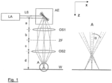
- FIG. 1 shows a schematic representation of an example of the proposed arrangement.
- Collimated laser radiation LS from a laser beam source LA is deflected by the deflection unit AE in two mutually perpendicular directions (X and Y directions).
- This deflection unit AE can be, for example, a two-dimensional galvanometer scanner.
- the figure shows three positions of one of the mirrors of the deflection unit AE with the resulting beam path of the laser radiation.
- the laser radiation strikes the first optical system OS1, in this example a focusing lens, at an angle to the optical axis.
- the laser radiation In the middle position of the mirror of the deflection unit AE shown, the laser radiation propagates along the optical axis through the first optical system OS1.
- An intermediate focus ZF is created at a distance b of the focal length of the first optical system OS1.
- the diverging laser radiation is then focused onto the workpiece W by the second optical system OS2.
- the second optical system OS2 is also formed solely by a focusing lens.
- the distances a, b, c and d between the deflection unit AE and the first optical system OS1, between the first optical system OS1 and the intermediate focus ZF, between the intermediate focus ZF and the second optical system OS2 and between the second optical system OS2 and the workpiece surface W, which in this example corresponds to the machining plane, are selected such that the laser beam crosses the optical axis before hitting the workpiece surface W.
- This is shown enlarged in the enlarged view of section A in the right-hand part of the figure.
- the offset of the laser beam from the center line or The optical axis which was created during the passage through the first optical system OS1 with the corresponding mirror position, leads to the laser beam being angled at an angle ⁇ and a helix point above the focal plane.
- the two optical systems OS1 and OS2 image a virtual point including a virtual deflection above the deflection unit AE, thus leading to an angle adjustment in a direction advantageous for the conicity of the desired bore.
- the desired hole By appropriately dynamically deflecting the laser beam LS with the deflection unit AE, the desired hole can be created.
- the angle of incidence on the workpiece surface is proportional to the offset of the laser beam between the two optical systems OS1, OS2 from the centerline or optical axis.
- both the proportionality factor and the focus diameter can be adjusted.
Landscapes
- Physics & Mathematics (AREA)
- Optics & Photonics (AREA)
- Engineering & Computer Science (AREA)
- Plasma & Fusion (AREA)
- Mechanical Engineering (AREA)
- Laser Beam Processing (AREA)
Description
- Die vorliegende Erfindung betrifft eine Anordnung zur Materialbearbeitung mit einem Laserstrahl, insbesondere zum Laserstrahl-Bohren, mit einer dynamischen Ablenkeinrichtung für den Laserstrahl, die zur Ablenkung des Laserstrahls in zwei senkrecht zueinander stehenden Richtungen ausgebildet ist, und einer optischen Anordnung, mit der ein aus der Ablenkeinrichtung austretender Laserstrahl auf eine Bearbeitungsebene fokussierbar ist.
- In der Materialbearbeitung mittels kurzen und ultrakurzen Laserpulsen zum Laserstrahl-Schneiden oder Laserstrahl-Bohren können mit typischen Bearbeitungsparametern bei senkrechter Einstrahlung keine steilen Wandwinkel erzielt werden. Der erreichbare Wandwinkel der Abtragsflanken liegt typischerweise im Bereich von maximal 85°. Dies liegt an der Verringerung der Pulsintensität bei Projektion auf die schräge Abtragsflanke, in Folge dessen der Abtrag ab einem Grenzwinkel gestoppt wird. Für viele Anwendungen ist dies allerdings unerwünscht, da bspw. keine senkrechten Schneidflanken oder nur konische Bohrungen möglich sind. Beim Tiefabtrag, Schneiden oder Bohren führt die Begrenzung des Wandwinkels auch zu einer Begrenzung im erzielbaren Aspektverhältnis (Abtragtiefe zu Durchmesser an Oberfläche).
- Für das Bohren und Feinschneiden mittels Laserstrahl sind Spezialoptiken verfügbar, die über verschiedene Verfahren den Laserstrahl so anstellen, dass eine zylindrische oder sogar negativ konische Bohrung erzeugt werden kann. Mit diesen Optiken wird der bei senkrechtem Einfall entstehende Wandwinkel durch die Anstellung des Laserstrahls gegenüber dem Werkstück ausgeglichen. Beim Feinschneiden wird während des Bohrens noch eine Relativbewegung zwischen Optik und Werkstück initiiert, wodurch ein Schnitt mit der Breite des Bohrlochdurchmessers erzeugt wird. Die verfügbaren Optiken lassen sich in Abhängigkeit vom Funktionsprinzip zur Anstellung des Laserstrahls in zwei Gruppen unterteilen. Bei der ersten Gruppe erfolgt die Strahlführung mit Hilfe von rotierenden optischen Elementen wie bspw. rotierenden Prismen, Zylinderlinsen oder Keilplatten. Die zweite Gruppe nutzt drehbare Spiegel für die gesamte Strahlführung, d. h. für Versatz, Anstellung und Ablenkung.
- Ein klassisches Anwendungsgebiet für das Laserbohren ist die Erzeugung präzisier Mikrobohrungen mit einigen 10 bis 100 µm Durchmesser in dünnen Folien mit Dicken meistens deutlich unter 1 mm. Häufig erfolgt das Bohren über ein Multi-pass Ausschneiden entlang der Bohrlochwand, es findet also kein Vollabtrag statt. Die Bohroptiken sind hierbei häufig auf einen maximalen Bohrlochdurchmesser in der Größenordnung von 1 mm ausgelegt. Für größere Bohrdurchmesser muss die Größe der drehbaren optischen Elemente erhöht werden, wobei die Ablenkgeschwindigkeit dabei nichtlinear reduziert wird.
- Die
DE 10 2018 208752 A1 (Basis für den Oberbegriff des Anspruchs 1) offenbart eine Anordnung zur Materialbearbeitung mit einem Laserstrahl, die ein Relay-System aus einer ersten und einer zweiten Relay-Optikgruppe aufweist. Im Anschluss an dieses Relay-System ist eine zusätzliche Fokussiereinheit erforderlich, um den Laserstrahl auf die Fokus- bzw. Bearbeitungsebene zu fokussieren. - Aus der
DE 100 54 853 A1 sind eine Vorrichtung und ein Verfahren zum Einbringen eines Mikrolochs mit einem Laserstrahl in ein Werkstück bekannt, bei denen der Laserstrahl auf das Werkstuck fokussiert und der Fokus fortlaufend auf einer zur Lochachse konzentrischen Kreisbahn entlangbewegt wird. - Die
EP 1 082 883 A1 beschreibt ein Verfahren und eine Vorrichtung zum Bohren von Mikrovias in elektrische Schaltungsträger oder Substrate mit einem Laserstrahl. Bei dem Verfahren werden die Vias mit einer speziellen, bspw. ringförmigen Intensitätsverteilung des Laserstrahls gebohrt, die über Stahlformungselemente erzeugt wird. - Aus der
EP 1 188 509 B1 ist eine optische Vorrichtung zum Bohren mittels Laserstrahl bekannt, bei der Anstellwinkel und Auslenkung zum Festlegen eines Trepanierradius getrennt voneinander einstellbar sind. Die Anordnung weist eine Ablenkeinrichtung mit zwei Ablenkspiegeln auf, bei der der optische Abstand wenigstens eines der Ablenkspiegel relativ zur Fokussieroptik parallel zur optischen Hauptachse änderbar ist. Dadurch kann der Laserstrahl in unterschiedlichen Winkeln auf die Fokussieroptik gerichtet werden, wodurch sich entsprechend der Position des Ablenkspiegels unterschiedliche Anstellwinkel ergeben. Die Fokussieroptik ist bei dieser Anordnung durch eine Fokussierlinse gebildet, durch die der Laserstrahl auf die Bearbeitungsebene fokussiert wird. Der Anstellwinkel kann bei dieser Ausgestaltung maximal so groß wie der Auslenkwinkel der Ablenkeinrichtung werden. Große Anstellwinkel lassen sich daher nur für große Konturen realisieren. - Die Aufgabe der vorliegenden Erfindung besteht darin, eine Anordnung zur Materialbearbeitung mit einem Laserstrahl anzugeben, mit der große und tiefe Bohrungen oder Schnitte mit einem einfachen und damit sehr günstigen und stabilen Aufbau erzeugt werden können und die auch vergleichsweise kleine Bohrungen mit einem großen Anstellwinkel ermöglicht.
- Die Aufgabe wird mit der Anordnung gemäß Patentanspruch 1 gelöst. Vorteilhafte Ausgestaltungen der Anordnung sind Gegenstand der abhängigen Patentansprüche oder lassen sich der nachfolgenden Beschreibung sowie dem Ausführungsbeispiel entnehmen.
- Die vorgeschlagene Anordnung weist eine dynamische Ablenkeinrichtung für den Laserstrahl, die zur Ablenkung des Laserstrahls in zwei senkrecht zueinander stehenden Richtungen ausgebildet ist, und eine optische Anordnung zwischen der Ablenkeinrichtung und einer Bearbeitungsebene auf, mit der ein aus der Ablenkeinrichtung austretender Laserstrahl auf die Bearbeitungsebene fokussiert wird. Bei der dynamischen Ablenkeinrichtung kann es sich bspw. um einen zweidimensionalen Galvanometerscanner handeln. Auch andere Arten derartiger Ablenkeinrichtungen für Laserstrahlen können selbstverständlich eingesetzt werden. Die optische Anordnung zur Fokussierung des aus der Ablenkeinrichtung austretenden Laserstrahls auf die Bearbeitungsebene weist wenigstens zwei optische Systeme entlang einer optischen Achse der optischen Anordnung auf. Als optisches System wird hierbei eine Anordnung aus einem oder mehreren strahlführenden und/oder strahlformenden optischen Elementen, bspw. einem oder mehreren Linsen, verstanden. Die optische Achse stellt die Symmetrieachse der optischen Anordnung dar, auf der ein eintretender Laserstrahl die optische Anordnung ohne Ablenkung passiert. Bei der vorgeschlagenen Anordnung sind das erste und das zweite optische System so ausgebildet und angeordnet, dass der auf die Bearbeitungsebene fokussierte Laserstrahl zwischen dem ersten und dem zweiten optischen System einen Zwischenfokus bildet und bei einem Eintritt in das optische System unter einem Winkel (≠ 0°) zur optischen Achse und beabstandet von dieser zwischen dem zweiten optischen System und der Bearbeitungsebene die optische Achse kreuzt. Der Eintritt in das optische System unter einem Winkel zur optischen Achse und beabstandet von dieser wird durch die dynamische Ablenkeinrichtung verursacht und stellt die gewünschte Betriebsweise der Anordnung zur Erzeugung eines Schnittes oder einer Bohrung eines Werkstückes dar, dessen zu bearbeitender Oberflächenbereich in der Bearbeitungsebene liegt, um auf diese Weise eine Anstellung des Laserstrahls (Winkel > 0° zur Oberflächennormalen) gegenüber dem Oberflächenbereich des Werkstücks zu erreichen. In der vorliegenden Patentanmeldung wird unter dem Eintritt des Lasers oder Laserstrahls unter einem Winkel zur optischen Achse und beabstandet von dieser und unter einer Kreuzung der optischen Achse durch den Laserstrahl in bekannter Weise verstanden, dass die Strahlachse des Laserstrahls unter einem Winkel zur optischen Achse und beabstandet von dieser verläuft bzw. die optische Achse kreuzt.
- Bei der vorgeschlagenen Anordnung wird mit der dynamischen Ablenkeinrichtung ein Winkelversatz gegenüber der optischen Achse der optischen Anordnung erzeugt. Der Laser trifft also unter einem Winkel zur optischen Achse und beabstandet zu dieser auf das erste optische System auf und wird durch das erste optische System auf einen Zwischenfokus zwischen erstem und zweitem optischen System fokussiert. Die nach dem Zwischenfokus divergierende Laserstrahlung wird dann durch das zweite optische System auf die Bearbeitungsebene bzw. die Werkstückoberfläche fokussiert. Der Versatz des Laserstrahls zur optischen Achse führt bei der vorgeschlagenen Anordnung zur Anstellung des Laserstrahls mit einem Wendelpunkt oberhalb der Bearbeitungsebene bzw. des Fokus. Auf diese Weise wird in der Bearbeitungsebene bzw. an der Oberfläche des Werkstücks eine für den zu erzielenden steilen Wandwinkel einer Bohrung geeignete Einstrahlrichtung erreicht. Mit dem vorgeschlagenen optischen Aufbau wird damit eine Winkelablenkung des Laserstrahls in Versatz und Anstell- bzw. Einstrahlwinkel aufgeteilt. Der Anstellwinkel ist dabei proportional zum Versatz zur optischen Achse, wobei der Proportionalitätsfaktor vom jeweils gewählten optischen Aufbau bzw. dessen Dimensionen abhängt. Durch den Wendelpunkt oberhalb der Bearbeitungsebene, in dem der Laserstrahl jeweils die optische Achse kreuzt, lassen sich auch kleine Bohrungen mit großem Anstellwinkel realisieren.
- Im Gegensatz zur bekannten Nutzung eines Relay-Systems wird in der vorgeschlagenen Anordnung durch die Nutzung von zwei optischen Systemen in definierten Abständen zueinander bereits eine Fokussierung der Laserstrahlung auf die Bearbeitungsebene erreicht, und zwar in der Weise, dass der Laserstrahl bei Eintritt in das erste optische System unter einem Winkel zur optischen Achse und beabstandet von dieser zwischen dem zweiten optischen System und der Bearbeitungsebene die optische Achse kreuzt.
- Demgegenüber bildet ein Relay-System lediglich die Ablenkebene auf eine Ebene hinter dem optischen System ab. Eine Fokussierung der Laserstrahlung kann anschließend über eine zusätzliche Fokussieroptik erreicht werden, deren Eintrittspupille in der abgebildeten Ablenkebene positioniert wird. Dies entspricht einem konventionellen Aufbau aus Ablenkeinrichtung und Fokussierlinse, bei der keine Kreuzung der optischen Achse zwischen der Fokussieroptik und der Bearbeitungsebene auftritt. Das Relay-System dient in diesem Fall nur dazu Ablenkeinrichtung und Fokussieroptik räumlich voneinander zu trennen oder im Zwischenfokus räumliche Filter einzusetzen.
- Der Durchmesser eines zu erzeugenden Bohrlochs und die Scangeschwindigkeit werden durch die Auslenkung und Drehrate der dynamischen Ablenkrichtung bestimmt. Abhängig von den Abständen zwischen den beiden optischen Systemen, zwischen der Ablenkeinrichtung und dem ersten optischen System und zwischen dem zweiten optischen System und der Bearbeitungs- bzw. Fokusebene und der Wahl der jeweiligen Brennweiten der optischen Systeme werden sowohl der Proportionalitätsfaktor als auch der Fokusdurchmesser eingestellt bzw. festgelegt. Bohrungen können mit der vorgeschlagenen Anordnung sowohl durch Ausschneiden als auch durch Vollabtrag erzeugt werden. So kann die Bohrungskontur durch entsprechende Ansteuerung der dynamischen Ablenkeinrichtung in mehreren Durchläufen mit dem Laserstrahl abgefahren und schichtweise abgetragen werden. Dieses Multi-pass Ausschneiden der Bohrungen entspricht dem typischen Verfahren bei Trepanieroptiken. Auf der anderen Seite kann auch durch das Abscannen der Querschnittsfläche des Bohrlochs über verschiedene Scanbewegungen ein schichtweiser Abtrag der gesamten Bohrungsfläche, also ein Vollabtrag erfolgen. Die Fläche kann hierbei durch entsprechende Ansteuerung der dynamischen Ablenkeinrichtung in unterschiedlicher Weise abgefahren werden, bspw. mittels konzentrischer Kreise oder in Spiralform. Auch andere Scanpfade sind für diesen Vollabtrag möglich.
- Mit der vorgeschlagenen Anordnung können positiv konische, zylindrische und auch negativ konische Bohrlöcher von bis zu mehreren mm Durchmessern erzeugt werden. Durch Vollabtrag kann die Fokusebene in die Bohrung hineingeschoben werden, ohne dass die Laserstrahlung hierbei abgeschirmt wird. Außerdem können auch dreidimensional geformte Bohrungen, also von einer Zylinderform abweichende Bohrungen, erzeugt werden. Beispiele sind die Erzeugung von Bohrungstrichtern, die Erzeugung sanduhrförmiger Bohrungen oder die Erzeugung von Bohrungen mit einer Laval-Düsenform. Mit Hilfe einer Relativbewegung des Werkstückes zur vorgeschlagenen Anordnung kann die Anordnung ebenfalls zum Wendelschneiden verwendet werden. Weiterhin kann so auch beim Mikrostrukturieren ein flächiger Abtrag mit senkrechten Abtragflanken oder auch Hinterschnitten erreicht werden.
- In einer bevorzugten Ausgestaltung werden das erste optische System und das zweite optische System jeweils aus einer Linse oder einer Linsenanordnung gebildet. Die Abstände der Linsen bzw. optischen Systeme zueinander und auch zur Ablenkeinrichtung und zur Bearbeitungsebene können hierbei fest vorgegeben sein. In einer vorteilhaften Ausgestaltung können einer oder mehrere dieser Abstände auch durch geeignete mechanische Stellelemente bzw. Verstellmechanismen an einem oder beiden optischen Systemen und/oder der Ablenkeinrichtung einstellbar sein.
- Zusätzlich zu der Ablenkeinrichtung und der sich an die Ablenkeinrichtung anschließenden optischen Anordnung können auch weitere Komponenten zur Strahlführung und/oder Strahlformung im Strahlengang des Laserstrahls angeordnet sein. So kann die vorgeschlagene Anordnung bspw. im Strahlengang vor der Ablenkeinrichtung ein Teleskop aufweisen, mit dem der Strahldurchmesser des Laserstrahls und damit auch der Fokusdurchmesser in der Bearbeitungsebene angepasst werden kann. Auch eine optische Einrichtung zur Vorfokussierung des Laserstrahls vor der Ablenkeinrichtung kann eingesetzt werden, um hierdurch ebenfalls den Fokusdurchmesser in der Bearbeitungsebene anpassen zu können. Es besteht auch die Möglichkeit durch geeignete drehende optische Elemente, bspw. ein um seine Längsachse rotierendes DOVE-Prisma, den Laserstrahl während der Materialbearbeitung zu drehen, wie dies von Anordnungen zum Wendelbohren mittels Laserstrahlung bekannt ist.
- In einer weiteren vorteilhaften Ausgestaltung sind eines oder mehrere geeignete Stellelemente vorgesehen, um die Fokusebene während der Bearbeitung senkrecht zur optischen Achse der optischen Anordnung verschieben oder anpassen zu können. Ein derartiger Z-Shift der Fokusebene kann durch eine Bewegung einer mechanischen z-Achse oder durch Verschiebung der optischen Elemente des ersten und/oder zweiten optischen Systems entlang der optischen Achse der optischen Anordnung erfolgen. Im Strahlengang des Laserstrahls können bei der vorgeschlagenen Anordnung auch Elemente zur Erzeugung einer linearen, zirkularen oder statistisch verteilten Polarisation der Laserstrahlung eingesetzt werden. Weiterhin besteht die Möglichkeit, die Polarisation über geeignete optische Elemente, wie bspw. λ/2 Platte, λ/4 Platte, DOVE-Prisma (synchron, asynchron) jeweils mitzudrehen.
- Bei der Materialbearbeitung mit der vorgeschlagenen Anordnung lassen sich vorzugsweise ein oder mehrere Verfahrens- und/oder Laserparameter während des Prozesses an den Prozessablauf anpassen. Bei den Laserparametern betrifft dies die Pulsenergie, die Pulsdauer sowie die Repetitionsrate, bei den Verfahrensparametern die Scangeometrie, die Scangeschwindigkeit, die Geschwindigkeit des Z-Shiftes, den Verlauf des Z-Shiftes sowie Wartezeiten zwischen einzelnen Bearbeitungsphasen. Zusätzlich können in bekannter Weise Prozessgase wie Luft, Inertgas oder Aktivgas während der Bearbeitung eingesetzt werden, bspw. durch Nutzung eines Crossjet oder einer koaxialen Düse, um dadurch einen verbesserten Abtransport der Ablationspartikel aus dem Wechselwirkungsbereich mit der Laserstrahlung zu erreichen.
- Mit dem vorgeschlagenen Verfahren lassen sich große und tiefe Bohrungen oder Schnitte mit einem sehr günstigen und stabilen Aufbau realisieren. Die vorgeschlagene Anordnung kann nachträglich in viele verfügbare Bearbeitungs- bzw. Strukturierungsanlagen integriert werden. Die Anordnung ermöglicht einen Vollabtrag des Bohrlochquerschnitts oder ein Ausschneiden mittels Spiral- oder Kreisfahrten mit jeweils angepasstem Anstellwinkel. Im einfachsten Fall verfügt die optische Anordnung nur über zwei Linsen, so dass nur geringe Verluste im optischen Strahlengang auftreten. Da in der optischen Anordnung keine sich bewegenden Komponenten angeordnet sind, weist die vorgeschlagene Anordnung einen einfachen, stabilen und günstigen Aufbau auf. Die Größe der mit der Anordnung herstellbaren Bohrungen ist nur durch den Durchmesser der beiden optischen Systeme begrenzt. Beim Wendelschneiden sind auch größere Schnitttiefen durch eine größere Schnittfuge möglich. Die vorgeschlagene Anordnung lässt sich bspw. zum Bohren im Turbomaschinenbau, der Elektronikfertigung oder der Halbleitertechnik, zum Wendelschneiden, bspw. in der Präzisionsmechanik oder Halbleitertechnik oder auch im Werkzeugbau und Flugzeugbau einsetzen.
- Die vorgeschlagene Anordnung wird nachfolgend anhand eines Ausführungsbeispiels in Verbindung mit der Zeichnung nochmals näher erläutert. Hierbei zeigt:
- Fig. 1
- ein Beispiel für eine Ausgestaltung der vorgeschlagenen Anordnung.
- Bei der vorgeschlagenen Anordnung wird ein Laserstrahl mittels einer Ablenkeinrichtung über eine optische Anordnung auf eine Werkstückoberfläche fokussiert, um von dieser Werkstückoberfläche Material abzutragen, insbesondere um Bohrlöcher oder Schnitte im Werkstück zu erzeugen.
Figur 1 zeigt in schematischer Darstellung einen beispielhaften Aufbau der vorgeschlagenen Anordnung. Bei dieser Darstellung wird kollimierte Laserstrahlung LS aus einer Laserstrahlquelle LA von der Ablenkeinheit AE in zwei senkrecht zueinander verlaufenden Richtungen (X- und Y-Richtung) abgelenkt. Bei dieser Ablenkeinheit AE kann es sich bspw. um einen zweidimensionalen Galvanometerscanner handeln. In der Figur sind hierbei drei Stellungen eines der Spiegel der Ablenkeinheit AE mit dem daraus resultierenden Strahlverlauf der Laserstrahlung zu erkennen. Die Laserstrahlung trifft in zwei der dargestellten drei Stellungen unter einem Winkel zur optischen Achse auf das erste optische System OS1, im vorliegenden Beispiel eine Fokussierlinse. In der mittleren Stellung des dargestellten Spiegels der Ablenkeinheit AE propagiert die Laserstrahlung entlang der optischen Achse durch das erste optische System OS1. Im Abstand b der Brennweite des ersten optischen Systems OS1 entsteht ein Zwischenfokus ZF. Anschließend wird die divergierende Laserstrahlung durch das zweite optische System OS2 auf das Werkstück W fokussiert. Auch das zweite optische System OS2 wird in diesem Beispiel lediglich durch eine Fokussierlinse gebildet. Die Abstände a, b, c und d zwischen der Ablenkeinheit AE und dem ersten optischen System OS1, zwischen dem ersten optischen System OS1 und dem Zwischenfokus ZF, zwischen dem Zwischenfokus ZF und dem zweiten optischen System OS2 und zwischen dem zweiten optischen System OS2 und der Werkstückoberfläche W, die in diesem Beispiel der Bearbeitungsebene entspricht, werden so gewählt, dass der Laserstrahl vor Auftreffen auf die Werkstückoberfläche W die optische Achse kreuzt. Dies ist in der vergrößerten Darstellung des Abschnittes A im rechten Teil der Figur vergrößert dargestellt. Der Versatz des Laserstrahls von der Mittellinie bzw. optischen Achse, der während des Durchlaufs durch das erste optische System OS1 bei entsprechender Spiegelstellung entstanden ist, führt zur Anstellung des Laserstrahls mit einem Winkel α und einem Wendelpunkt oberhalb der Fokusebene. Die beiden optischen Systeme OS1, OS2 bilden einen virtuellen Punkt samt virtueller Auslenkung oberhalb der Ablenkeinheit AE ab und führen so zu einer Anstellung in eine für die Konizität der gewünschten Bohrung vorteilhaften Richtung. - Durch entsprechende dynamische Ablenkung des Laserstrahls LS mit der Ablenkeinheit AE kann so die gewünschte Bohrung erzeugt werden. Der Einstrahlwinkel auf die Werkstückoberfläche ist dabei jeweils proportional zum Versatz des Laserstrahls zwischen den beiden optischen Systemen OS1, OS2 zur Mittellinie bzw. optischen Achse. Durch Änderung der Abstände a, b, c und d und geeignete Wahl der Brennweiten der optischen Systeme OS1, OS2 können sowohl der Proportionalitätsfaktor als auch der Fokusdurchmesser eingestellt werden.
- Mit der folgenden beispielhaften Dimensionierung der Anordnung lässt sich bspw. eine Bohrung mit einem Durchmesser von 500 µm in einem Werkstück aus 5 mm dicker Nickelbasislegierung erzeugen. Dabei wird eine Pulsenergie von ~1 mJ bei einem Fokusdurchmesser von 40 µm und einer Pulsdauer < 20 ps verwendet und es findet ein Vollabtrag durch Spiralen statt. Die in
Figur 1 dargestellten Parameter werden dabei wie folgt gewählt:


- Brennweite der Linse OS1: 500 mm
- Brennweite der Linse OS2: 70 mm
-
- AE
- Ablenkeinheit
- LA
- Laserstrahlquelle
- LS
- Laserstrahl
- OS1
- erstes optisches System
- OS2
- zweites optisches System
- W
- Werkstückoberfläche
- ZF
- Zwischenfokus
- a - d
- Abstände
Claims (9)
- Anordnung zur Materialbearbeitung mit einem Laserstrahl, insbesondere zum Laserstrahl-Bohren, mit- einer dynamischen Ablenkeinrichtung (AE) für den Laserstrahl (LS), die zur Ablenkung des Laserstrahls (LS) in zwei senkrecht zueinander stehenden Richtungen ausgebildet ist, und- einer optischen Anordnung, mit der ein aus der Ablenkeinrichtung (AE) austretender Laserstrahl auf eine Bearbeitungsebene (W) fokussiert wird,- wobei die optische Anordnung entlang einer optischen Achse der optischen Anordnung ein erstes optisches System (OS1) und ein zweites optisches System (OS2) aufweist, die so ausgebildet und angeordnet sind, dass der Laserstrahl (LS) zwischen dem ersten und dem zweiten optischen System (OS1, OS2) einen Zwischenfokus (ZF) bildet, dadurch gekennzeichnet, dass der Laserstrahl bei Eintritt in das erste optische System (OS1) unter einem Winkel zur optischen Achse und beabstandet zu dieser zwischen dem zweiten optischen System (OS2) und der Bearbeitungsebene (W) die optische Achse kreuzt.
- Anordnung nach Anspruch 1,
dadurch gekennzeichnet,
dass an einem der beiden optischen Systeme (OS1, OS2) oder an beiden optischen Systemen (OS1, OS2) eines oder mehrere Stellelemente angebracht sind, mit dem oder denen ein Abstand zwischen den beiden optischen Systemen (OS1, OS2) und/oder ein Abstand des ersten optischen Systems (OS1) zur Ablenkeinheit (AE) und/oder ein Abstand des zweiten optischen Systems (OS2) zur Bearbeitungsebene (W) einstell- oder veränderbar ist. - Anordnung nach Anspruch 1 oder 2,
dadurch gekennzeichnet,
dass im Strahlengang des Laserstrahls (LS) vor der Ablenkeinrichtung (AE) ein Teleskop angeordnet ist, mit dem ein Strahldurchmesser des Laserstrahls (LS) verändert werden kann. - Anordnung nach Anspruch 1 oder 2,
dadurch gekennzeichnet,
dass im Strahlengang des Laserstrahls (LS) vor der optischen Anordnung oder der Ablenkeinrichtung (AE) eine optische Einrichtung zur Vorfokussierung des Laserstrahls (LS) angeordnet ist. - Anordnung nach Anspruch 4,
dadurch gekennzeichnet,
dass die optische Einrichtung zur Vorfokussierung so ausgebildet ist, dass sie eine variable Vorfokussierung des Laserstrahls (LS) ermöglicht. - Anordnung nach einem der Ansprüche 1 bis 5,
dadurch gekennzeichnet,
dass die optische Anordnung eines oder mehrere Stellelemente aufweist, mit dem oder denen eine Fokusebene des Laserstrahls (LS) während der Materialbearbeitung entlang der optischen Achse der optischen Anordnung verschoben werden kann. - Anordnung nach einer der Ansprüche 1 bis 6,
dadurch gekennzeichnet,
dass die optische Anordnung mindestens ein Element zur Beeinflussung der Polarisation aufweist, wodurch eine für die Materialbearbeitung vorteilhafte Polarisation eingestellt werden kann. - Verwendung der Anordnung nach einem oder mehreren der vorangehenden Ansprüche zur Erzeugung eines Bohrlochs durch schichtweisen Vollabtrag, bei dem ein Bohrlochquerschnitt jeweils vollständig mit dem Laserstrahl abgefahren wird.
- Verwendung der Anordnung nach einem oder mehreren der vorangehenden Ansprüche zur Erzeugung eines Bohrlochs durch Ausschneiden einer Bohrlochkontur mittels Spiral- oder Kreisfahrten mit dem Laserstrahl.
Applications Claiming Priority (2)
| Application Number | Priority Date | Filing Date | Title |
|---|---|---|---|
| DE102020201207.5A DE102020201207A1 (de) | 2020-01-31 | 2020-01-31 | Anordnung zur Materialbearbeitung mit einem Laserstrahl, insbesondere zum Laserstrahl-Bohren |
| PCT/EP2021/051977 WO2021152008A1 (de) | 2020-01-31 | 2021-01-28 | Anordnung zur materialbearbeitung mit einem laserstrahl, insbesondere zum laserstrahl-bohren |
Publications (2)
| Publication Number | Publication Date |
|---|---|
| EP4096860A1 EP4096860A1 (de) | 2022-12-07 |
| EP4096860B1 true EP4096860B1 (de) | 2025-06-18 |
Family
ID=74586983
Family Applications (1)
| Application Number | Title | Priority Date | Filing Date |
|---|---|---|---|
| EP21704427.0A Active EP4096860B1 (de) | 2020-01-31 | 2021-01-28 | Anordnung zur materialbearbeitung mit einem laserstrahl, insbesondere zum laserstrahl-bohren |
Country Status (7)
| Country | Link |
|---|---|
| US (1) | US12515279B2 (de) |
| EP (1) | EP4096860B1 (de) |
| JP (1) | JP7710452B2 (de) |
| KR (1) | KR102860749B1 (de) |
| CN (1) | CN115379922A (de) |
| DE (1) | DE102020201207A1 (de) |
| WO (1) | WO2021152008A1 (de) |
Families Citing this family (1)
| Publication number | Priority date | Publication date | Assignee | Title |
|---|---|---|---|---|
| WO2025105196A1 (ja) * | 2023-11-13 | 2025-05-22 | デクセリアルズ株式会社 | 個片フィルムの製造方法及び個片フィルム、並びに接続構造体の製造方法及び接続構造体 |
Citations (2)
| Publication number | Priority date | Publication date | Assignee | Title |
|---|---|---|---|---|
| EP1082883B1 (de) * | 1998-05-29 | 2002-10-16 | Exitech Limited | Vorrichtung und verfahren zur perforierung von mikrovia-löchern in verpackungen von elektrischen verbindungsstellen von elektrischen schaltungen |
| DE102005013949A1 (de) * | 2005-03-26 | 2006-09-28 | Carl Zeiss Meditec Ag | Scanvorrichtung |
Family Cites Families (35)
| Publication number | Priority date | Publication date | Assignee | Title |
|---|---|---|---|---|
| FR2437008B1 (fr) * | 1978-09-20 | 1985-06-28 | Philip Morris Inc | Appareil de production de faisceaux lumineux pulses |
| JP3216987B2 (ja) * | 1996-03-15 | 2001-10-09 | 三菱電機株式会社 | レーザ転写加工装置およびレーザ転写加工方法 |
| US6433303B1 (en) * | 2000-03-31 | 2002-08-13 | Matsushita Electric Industrial Co., Ltd. | Method and apparatus using laser pulses to make an array of microcavity holes |
| DE10045973A1 (de) | 2000-09-16 | 2002-04-04 | Bosch Gmbh Robert | Optische Vorrichtung zum Bohren mittels Laserstrahl |
| DE10054853A1 (de) * | 2000-11-06 | 2002-08-01 | Bosch Gmbh Robert | Verfahren zum Einbringen eines Mikrolochs in ein vorzugsweise metallisches Werkstück und Vorrichtung hierzu |
| JP4069348B2 (ja) * | 2001-02-22 | 2008-04-02 | トヨタ自動車株式会社 | レーザ加工方法およびレーザ加工装置 |
| US6803539B2 (en) | 2002-07-25 | 2004-10-12 | Matsushita Electrical Industrial Co., Ltd. | System and method of aligning a microfilter in a laser drilling system using a CCD camera |
| JP2004261822A (ja) * | 2003-02-28 | 2004-09-24 | Fine Device:Kk | レーザ加工装置 |
| JP2004337925A (ja) * | 2003-05-15 | 2004-12-02 | Mitsubishi Electric Corp | レーザ加工機 |
| US8237082B2 (en) * | 2004-09-02 | 2012-08-07 | Siemens Aktiengesellschaft | Method for producing a hole |
| US20080013182A1 (en) * | 2006-07-17 | 2008-01-17 | Joerg Ferber | Two-stage laser-beam homogenizer |
| US20090312859A1 (en) * | 2008-06-16 | 2009-12-17 | Electro Scientific Industries, Inc. | Modifying entry angles associated with circular tooling actions to improve throughput in part machining |
| KR101057458B1 (ko) * | 2008-11-03 | 2011-08-17 | 주식회사 이오테크닉스 | 드릴링 장치 및 드릴링 방법 |
| US8338745B2 (en) * | 2009-12-07 | 2012-12-25 | Panasonic Corporation | Apparatus and methods for drilling holes with no taper or reverse taper |
| US8525073B2 (en) * | 2010-01-27 | 2013-09-03 | United Technologies Corporation | Depth and breakthrough detection for laser machining |
| DE202010006047U1 (de) | 2010-04-22 | 2010-07-22 | Trumpf Werkzeugmaschinen Gmbh + Co. Kg | Strahlformungseinheit zur Fokussierung eines Laserstrahls |
| DE102011006085A1 (de) | 2011-03-25 | 2012-09-27 | Carl Zeiss Meditec Ag | Ophthalmologisches Gerät |
| JP5758237B2 (ja) * | 2011-09-01 | 2015-08-05 | 株式会社豊田中央研究所 | レーザ加工装置及びレーザ加工方法 |
| JP5994723B2 (ja) * | 2013-05-09 | 2016-09-21 | トヨタ自動車株式会社 | レーザ穴あけ加工方法および装置 |
| US11648623B2 (en) * | 2014-07-14 | 2023-05-16 | Corning Incorporated | Systems and methods for processing transparent materials using adjustable laser beam focal lines |
| GB2529808B (en) * | 2014-08-26 | 2018-07-25 | M Solv Ltd | Apparatus and methods for performing laser ablation on a substrate |
| KR101527482B1 (ko) * | 2014-11-25 | 2015-06-10 | 유수영 | 레이저를 이용한 미세 부품 가공 장치 |
| US9873628B1 (en) * | 2014-12-02 | 2018-01-23 | Coherent Kaiserslautern GmbH | Filamentary cutting of brittle materials using a picosecond pulsed laser |
| US11077526B2 (en) * | 2015-09-09 | 2021-08-03 | Electro Scientific Industries, Inc. | Laser processing apparatus, methods of laser-processing workpieces and related arrangements |
| CN105436703A (zh) * | 2015-12-30 | 2016-03-30 | 常州英诺激光科技有限公司 | 一种适用于硬脆基板的激光钻微孔设备及方法 |
| JP6616368B2 (ja) * | 2017-09-14 | 2019-12-04 | ファナック株式会社 | レーザ加工前に光学系の汚染レベルに応じて加工条件を補正するレーザ加工装置 |
| WO2019064325A1 (ja) * | 2017-09-26 | 2019-04-04 | 三菱電機株式会社 | レーザ加工方法およびレーザ加工装置 |
| US20190151993A1 (en) * | 2017-11-22 | 2019-05-23 | Asm Technology Singapore Pte Ltd | Laser-cutting using selective polarization |
| WO2019183445A1 (en) * | 2018-03-23 | 2019-09-26 | Lawrence Livermore National Security, Llc | Laser drilling and machining enhancement using gated cw and short pulsed lasers |
| DE102018208752B4 (de) * | 2018-06-04 | 2024-08-22 | Fraunhofer-Gesellschaft zur Förderung der angewandten Forschung e.V. | Vorrichtung und Verfahren zur Bearbeitung zur Bearbeitung schwer zugänglicher Werkstücke sowie Verwendung einer Vorrichtung |
| CN108890151A (zh) * | 2018-07-19 | 2018-11-27 | 深圳市吉祥云科技有限公司 | 一种光伏玻璃打孔方法 |
| TWI866446B (zh) * | 2018-10-08 | 2024-12-11 | 美商伊雷克托科學工業股份有限公司 | 用於在基板中形成穿孔的方法 |
| CN109530913B (zh) * | 2018-12-25 | 2021-07-23 | 武汉华工激光工程有限责任公司 | 一种贝塞尔光束的激光加工优化方法及系统 |
| TWI843784B (zh) * | 2019-01-31 | 2024-06-01 | 美商伊雷克托科學工業股份有限公司 | 雷射加工設備、與設備一起使用的控制器及非暫時性電腦可讀取媒體 |
| CN110449731B (zh) * | 2019-08-27 | 2023-07-04 | 华中科技大学 | 一种激光变锥变径旋切孔加工光学系统 |
-
2020
- 2020-01-31 DE DE102020201207.5A patent/DE102020201207A1/de active Pending
-
2021
- 2021-01-28 EP EP21704427.0A patent/EP4096860B1/de active Active
- 2021-01-28 US US17/796,444 patent/US12515279B2/en active Active
- 2021-01-28 WO PCT/EP2021/051977 patent/WO2021152008A1/de not_active Ceased
- 2021-01-28 KR KR1020227026462A patent/KR102860749B1/ko active Active
- 2021-01-28 CN CN202180011782.7A patent/CN115379922A/zh active Pending
- 2021-01-28 JP JP2022545969A patent/JP7710452B2/ja active Active
Patent Citations (2)
| Publication number | Priority date | Publication date | Assignee | Title |
|---|---|---|---|---|
| EP1082883B1 (de) * | 1998-05-29 | 2002-10-16 | Exitech Limited | Vorrichtung und verfahren zur perforierung von mikrovia-löchern in verpackungen von elektrischen verbindungsstellen von elektrischen schaltungen |
| DE102005013949A1 (de) * | 2005-03-26 | 2006-09-28 | Carl Zeiss Meditec Ag | Scanvorrichtung |
Also Published As
| Publication number | Publication date |
|---|---|
| DE102020201207A1 (de) | 2021-08-05 |
| CN115379922A (zh) | 2022-11-22 |
| WO2021152008A1 (de) | 2021-08-05 |
| EP4096860A1 (de) | 2022-12-07 |
| KR20220130714A (ko) | 2022-09-27 |
| JP2023512236A (ja) | 2023-03-24 |
| US12515279B2 (en) | 2026-01-06 |
| KR102860749B1 (ko) | 2025-09-16 |
| US20230339047A1 (en) | 2023-10-26 |
| JP7710452B2 (ja) | 2025-07-18 |
Similar Documents
| Publication | Publication Date | Title |
|---|---|---|
| EP2673106B1 (de) | Vorrichtung, anordnung und verfahren zur interferenzstrukturierung von flächigen proben | |
| DE3934587C2 (de) | Verfahren zum Herstellen von mittels Laserstrahlung erzeugter, hochpräziser Durchgangsbohrungen in Werkstücken | |
| EP2976176B1 (de) | Verfahren und anordnung zur ausbildung einer strukturierung an oberflächen von bauteilen mit einem laserstrahl | |
| EP2596899B1 (de) | Vorrichtung und Verfahren zur Interferenzstrukturierung von flächigen Proben | |
| EP4200101B1 (de) | Verfahren zur herstellung mindestens eines werkstückteils und eines restwerkstücks aus einem werkstück | |
| DE202008017745U1 (de) | Vorrichtung zum Führen eines Lichtstrahls | |
| EP3965990B1 (de) | Verfahren und strahlbearbeitungsvorrichtung zur strahlbearbeitung eines werkstücks | |
| WO2003015978A1 (de) | Verfahren und vorrichtung zum einbringen von löchern in werkstücke mittels laserstrahlen | |
| EP3154740B1 (de) | Vorrichtung zur lasermaterialbearbeitung mit einer parallel-versatz-einheit | |
| WO2001039920A1 (de) | Vorrichtung zum bearbeiten von substraten und verfahren unter verwendung einer solchen vorrichtung | |
| DE102020205948A1 (de) | Laserschneidverfahren und Laserschneidanlage | |
| WO2000030802A1 (de) | Vorrichtung und verfahren zum abtasten einer objektfläche mit einem laserstrahl | |
| DE102013222834A1 (de) | Vorrichtung und Verfahren zur Führung eines Laserstrahls | |
| EP4238687B1 (de) | Verfahren zur bearbeitung eines platten- oder rohrförmigen werkstücks | |
| DE10054853A1 (de) | Verfahren zum Einbringen eines Mikrolochs in ein vorzugsweise metallisches Werkstück und Vorrichtung hierzu | |
| DE19817851C1 (de) | Verfahren zum Ablenken eines Laserstrahls | |
| DE102014206358A1 (de) | Verfahren und Laserschneidmaschine zum Laserschneiden kleiner Öffnungen | |
| EP4096860B1 (de) | Anordnung zur materialbearbeitung mit einem laserstrahl, insbesondere zum laserstrahl-bohren | |
| EP1291117B1 (de) | Verfahren zum Erzeugen einer Bohrung in einem Werkstück mit Laserstrahlung | |
| DE102017105955A1 (de) | Laserschleifvorrichtung sowie Verfahren zum Bearbeiten eines Werkstückes | |
| DE102004050047A1 (de) | Verfahren und Vorrichtung zur Erzeugung von Bohrungen mittels Laser | |
| EP0683007B1 (de) | Materialbearbeitungseinrichtung | |
| DE10140533A1 (de) | Verfahren und Vorrichtung zur Mikrobearbeitung eines Werkstücks mit Laserstrahlung | |
| WO2006000549A1 (de) | Laserbearbeitungsmaschine zum bohren von löchern in ein werkstück mit einer optischen auslenkvorrichtung und einer ablenkeinheit | |
| DE4202941C2 (de) | Verfahren zum Materialabtrag an einem bewegten Werkstück |
Legal Events
| Date | Code | Title | Description |
|---|---|---|---|
| STAA | Information on the status of an ep patent application or granted ep patent |
Free format text: STATUS: UNKNOWN |
|
| STAA | Information on the status of an ep patent application or granted ep patent |
Free format text: STATUS: THE INTERNATIONAL PUBLICATION HAS BEEN MADE |
|
| PUAI | Public reference made under article 153(3) epc to a published international application that has entered the european phase |
Free format text: ORIGINAL CODE: 0009012 |
|
| STAA | Information on the status of an ep patent application or granted ep patent |
Free format text: STATUS: REQUEST FOR EXAMINATION WAS MADE |
|
| 17P | Request for examination filed |
Effective date: 20220811 |
|
| AK | Designated contracting states |
Kind code of ref document: A1 Designated state(s): AL AT BE BG CH CY CZ DE DK EE ES FI FR GB GR HR HU IE IS IT LI LT LU LV MC MK MT NL NO PL PT RO RS SE SI SK SM TR |
|
| DAV | Request for validation of the european patent (deleted) | ||
| DAX | Request for extension of the european patent (deleted) | ||
| GRAP | Despatch of communication of intention to grant a patent |
Free format text: ORIGINAL CODE: EPIDOSNIGR1 |
|
| STAA | Information on the status of an ep patent application or granted ep patent |
Free format text: STATUS: GRANT OF PATENT IS INTENDED |
|
| INTG | Intention to grant announced |
Effective date: 20250203 |
|
| GRAS | Grant fee paid |
Free format text: ORIGINAL CODE: EPIDOSNIGR3 |
|
| GRAA | (expected) grant |
Free format text: ORIGINAL CODE: 0009210 |
|
| STAA | Information on the status of an ep patent application or granted ep patent |
Free format text: STATUS: THE PATENT HAS BEEN GRANTED |
|
| AK | Designated contracting states |
Kind code of ref document: B1 Designated state(s): AL AT BE BG CH CY CZ DE DK EE ES FI FR GB GR HR HU IE IS IT LI LT LU LV MC MK MT NL NO PL PT RO RS SE SI SK SM TR |
|
| REG | Reference to a national code |
Ref country code: GB Ref legal event code: FG4D Free format text: NOT ENGLISH |
|
| REG | Reference to a national code |
Ref country code: CH Ref legal event code: EP |
|
| REG | Reference to a national code |
Ref country code: DE Ref legal event code: R096 Ref document number: 502021007777 Country of ref document: DE |
|
| REG | Reference to a national code |
Ref country code: CH Ref legal event code: EP |
|
| REG | Reference to a national code |
Ref country code: IE Ref legal event code: FG4D Free format text: LANGUAGE OF EP DOCUMENT: GERMAN |
|
| PG25 | Lapsed in a contracting state [announced via postgrant information from national office to epo] |
Ref country code: FI Free format text: LAPSE BECAUSE OF FAILURE TO SUBMIT A TRANSLATION OF THE DESCRIPTION OR TO PAY THE FEE WITHIN THE PRESCRIBED TIME-LIMIT Effective date: 20250618 |
|
| REG | Reference to a national code |
Ref country code: LT Ref legal event code: MG9D |
|
| PG25 | Lapsed in a contracting state [announced via postgrant information from national office to epo] |
Ref country code: NO Free format text: LAPSE BECAUSE OF FAILURE TO SUBMIT A TRANSLATION OF THE DESCRIPTION OR TO PAY THE FEE WITHIN THE PRESCRIBED TIME-LIMIT Effective date: 20250918 Ref country code: GR Free format text: LAPSE BECAUSE OF FAILURE TO SUBMIT A TRANSLATION OF THE DESCRIPTION OR TO PAY THE FEE WITHIN THE PRESCRIBED TIME-LIMIT Effective date: 20250919 |
|
| PG25 | Lapsed in a contracting state [announced via postgrant information from national office to epo] |
Ref country code: BG Free format text: LAPSE BECAUSE OF FAILURE TO SUBMIT A TRANSLATION OF THE DESCRIPTION OR TO PAY THE FEE WITHIN THE PRESCRIBED TIME-LIMIT Effective date: 20250618 |
|
| PG25 | Lapsed in a contracting state [announced via postgrant information from national office to epo] |
Ref country code: HR Free format text: LAPSE BECAUSE OF FAILURE TO SUBMIT A TRANSLATION OF THE DESCRIPTION OR TO PAY THE FEE WITHIN THE PRESCRIBED TIME-LIMIT Effective date: 20250618 |
|
| PG25 | Lapsed in a contracting state [announced via postgrant information from national office to epo] |
Ref country code: RS Free format text: LAPSE BECAUSE OF FAILURE TO SUBMIT A TRANSLATION OF THE DESCRIPTION OR TO PAY THE FEE WITHIN THE PRESCRIBED TIME-LIMIT Effective date: 20250918 |
|
| REG | Reference to a national code |
Ref country code: NL Ref legal event code: MP Effective date: 20250618 |
|
| PG25 | Lapsed in a contracting state [announced via postgrant information from national office to epo] |
Ref country code: LV Free format text: LAPSE BECAUSE OF FAILURE TO SUBMIT A TRANSLATION OF THE DESCRIPTION OR TO PAY THE FEE WITHIN THE PRESCRIBED TIME-LIMIT Effective date: 20250618 |
|
| PG25 | Lapsed in a contracting state [announced via postgrant information from national office to epo] |
Ref country code: NL Free format text: LAPSE BECAUSE OF FAILURE TO SUBMIT A TRANSLATION OF THE DESCRIPTION OR TO PAY THE FEE WITHIN THE PRESCRIBED TIME-LIMIT Effective date: 20250618 |
|
| PG25 | Lapsed in a contracting state [announced via postgrant information from national office to epo] |
Ref country code: PT Free format text: LAPSE BECAUSE OF FAILURE TO SUBMIT A TRANSLATION OF THE DESCRIPTION OR TO PAY THE FEE WITHIN THE PRESCRIBED TIME-LIMIT Effective date: 20251020 |
|
| PG25 | Lapsed in a contracting state [announced via postgrant information from national office to epo] |
Ref country code: IS Free format text: LAPSE BECAUSE OF FAILURE TO SUBMIT A TRANSLATION OF THE DESCRIPTION OR TO PAY THE FEE WITHIN THE PRESCRIBED TIME-LIMIT Effective date: 20251018 |
|
| PG25 | Lapsed in a contracting state [announced via postgrant information from national office to epo] |
Ref country code: SM Free format text: LAPSE BECAUSE OF FAILURE TO SUBMIT A TRANSLATION OF THE DESCRIPTION OR TO PAY THE FEE WITHIN THE PRESCRIBED TIME-LIMIT Effective date: 20250618 |
|
| PG25 | Lapsed in a contracting state [announced via postgrant information from national office to epo] |
Ref country code: CZ Free format text: LAPSE BECAUSE OF FAILURE TO SUBMIT A TRANSLATION OF THE DESCRIPTION OR TO PAY THE FEE WITHIN THE PRESCRIBED TIME-LIMIT Effective date: 20250618 |
|
| PG25 | Lapsed in a contracting state [announced via postgrant information from national office to epo] |
Ref country code: PL Free format text: LAPSE BECAUSE OF FAILURE TO SUBMIT A TRANSLATION OF THE DESCRIPTION OR TO PAY THE FEE WITHIN THE PRESCRIBED TIME-LIMIT Effective date: 20250618 |
|
| PG25 | Lapsed in a contracting state [announced via postgrant information from national office to epo] |
Ref country code: EE Free format text: LAPSE BECAUSE OF FAILURE TO SUBMIT A TRANSLATION OF THE DESCRIPTION OR TO PAY THE FEE WITHIN THE PRESCRIBED TIME-LIMIT Effective date: 20250618 |
|
| PG25 | Lapsed in a contracting state [announced via postgrant information from national office to epo] |
Ref country code: SK Free format text: LAPSE BECAUSE OF FAILURE TO SUBMIT A TRANSLATION OF THE DESCRIPTION OR TO PAY THE FEE WITHIN THE PRESCRIBED TIME-LIMIT Effective date: 20250618 |
|
| PG25 | Lapsed in a contracting state [announced via postgrant information from national office to epo] |
Ref country code: ES Free format text: LAPSE BECAUSE OF FAILURE TO SUBMIT A TRANSLATION OF THE DESCRIPTION OR TO PAY THE FEE WITHIN THE PRESCRIBED TIME-LIMIT Effective date: 20250618 |