EP4096470B1 - Haarkamm und applikatorvorrichtung - Google Patents
Haarkamm und applikatorvorrichtung Download PDFInfo
- Publication number
- EP4096470B1 EP4096470B1 EP21701782.1A EP21701782A EP4096470B1 EP 4096470 B1 EP4096470 B1 EP 4096470B1 EP 21701782 A EP21701782 A EP 21701782A EP 4096470 B1 EP4096470 B1 EP 4096470B1
- Authority
- EP
- European Patent Office
- Prior art keywords
- roller
- hair
- applicator device
- hair comb
- wall
- Prior art date
- Legal status (The legal status is an assumption and is not a legal conclusion. Google has not performed a legal analysis and makes no representation as to the accuracy of the status listed.)
- Active
Links
Images


Classifications
-
- A—HUMAN NECESSITIES
- A45—HAND OR TRAVELLING ARTICLES
- A45D—HAIRDRESSING OR SHAVING EQUIPMENT; EQUIPMENT FOR COSMETICS OR COSMETIC TREATMENTS, e.g. FOR MANICURING OR PEDICURING
- A45D24/00—Hair combs for care of the hair; Accessories therefor
- A45D24/22—Combs with dispensing devices for liquids, pastes or powders
- A45D24/24—Combs with dispensing devices for liquids, pastes or powders with provision for free supply; using wicks
-
- A—HUMAN NECESSITIES
- A45—HAND OR TRAVELLING ARTICLES
- A45D—HAIRDRESSING OR SHAVING EQUIPMENT; EQUIPMENT FOR COSMETICS OR COSMETIC TREATMENTS, e.g. FOR MANICURING OR PEDICURING
- A45D24/00—Hair combs for care of the hair; Accessories therefor
- A45D24/04—Multi-part combs
- A45D24/10—Multi-part combs combined with additional devices
-
- A—HUMAN NECESSITIES
- A46—BRUSHWARE
- A46B—BRUSHES
- A46B11/00—Brushes with reservoir or other means for applying substances, e.g. paints, pastes, water
- A46B11/0072—Details
- A46B11/0079—Arrangements for preventing undesired leakage or dispensing
- A46B11/0082—Means for closing, sealing or controlling the flow using capillary action
-
- A—HUMAN NECESSITIES
- A46—BRUSHWARE
- A46B—BRUSHES
- A46B2200/00—Brushes characterized by their functions, uses or applications
- A46B2200/10—For human or animal care
- A46B2200/104—Hair brush
Definitions
- the present invention relates to combined hair comb and applicator device.
- Hair is typically maintained using either comb or brush type devices.
- hair care it is also commonplace to apply therapeutic or cosmetic substances to hair.
- hair sprays, creams or colouring agents may be applied during or prior to brushing hair with a comb or brush.
- hair treatment substance which may include, without limitation, substances for hair cleaning, hair care and therapeutic or cosmetic hair treatment.
- Existing applicator devices may be unsuitable for use with all types of hair treatment products.
- the spray device of US 9,210,982 may only be suitable for liquid products which are relatively thin (have low viscosity) since thicker substances may tend to clog a spray nozzle.
- Higher viscosity hair treatment products may, for example include pastes or creams and may for example include products which are intended to be applied to the roots of tightly curled hair (for example Afro type hair).
- a hair comb and applicator device comprising: a body enclosing a reservoir for containing a hair treatment substance; a plurality of teeth arranged in at least one row; and a roller, rotatably mounted within the body, to transfer hair treatment substance from the reservoir to hair during use; wherein the body includes a wall comprising: a concave inner surface providing a seat for the roller; a convex outer surface from which the plurality of teeth extend; and wherein a plurality of through slots are provided in the wall, the slots being interposed between the plurality of teeth and wherein each slot extends as an arc along the wall.
- the wall may be contiguous with boundaries of the reservoir.
- the body of the device may define the reservoir and the wall may be a forward portion of the body.
- the body may be externally profiled to provide a graspable handle portion and the wall may extend away from the handle portion.
- the reservoir may be closed by the body with the roller interacting with the slots to enable application of hair treatment substance from the reservoir onto hair.
- the roller of the device may function as both an applicator and a closing member for the reservoir.
- the roller when the device is not in use, the roller is typically stationary, and the reservoir may be effectively closed. Since the reservoir may be effectively closed (and for example sealed) when the device is not in use the device may be suitable for use in both wet and dry environments. In wet environments ingress of water into the reservoir may be avoided and in dry environments leakage of the treatment substance from the reservoir may be avoided.
- arc shaped slots along a convex wall has been found to provide an advantageous arrangement in providing a good contact area between the roller and the hair in use.
- embodiments of the invention have been found to provide effective transfer of hair treatment substance from the reservoir to hair even when using relatively high viscosity substances. It is believed that this is effective in both ensure that frictional engagement between the hair and the roller rotates the roller relative to the body and that a lengthwise area of the hair is able to be brought into contact with the roller.
- the wall extends outwardly from the housing.
- the wall may conform closely to the profile of the roller to ensure good contact between extending outwardly from the housing.
- the conformal nature of the wall and the roller may ensure that the slots are extend along the surface of the roller.
- the wall may for example be formed as a longitudinal cylinder segment. Each slot may extend circumferentially around the cylinder segment.
- the longitudinal cylinder segment may have a central angle of greater than 90 degrees, for example the central angle may be obtuse.
- the cylindrical segment may be at least a quadrant of a cylinder.
- the wall may define a semi-cylinder profile.
- a cylindrical segment having a central angle of greater than 90 degrees may ensure that the curvature of the wall is pronounced and that the slots extend around a significant proportion.
- each slot may extend longitudinally around a circular segment having an arc length with a central angle of greater than 90 degrees.
- the teeth may extend radially outward relative to the cylinder.
- the teeth may be configured as a wide toothed comb, for example such an arrangement is advantageous for afro hair.
- the spacing between adjacent teeth may be at least 5mm and may for example be approximately 1cm.
- Each tooth may for example be blade-shaped. It will be appreciated that a blade shaped tooth may have a generally thin and flat cross-sectional profile. For example, each blade may have an elongate cross sectional. The lengthwise direction of the cross section at the root of the blade is generally aligned with, for example parallel to, the longitudinal direction of an adjacent slot.
- the blade shaped teeth may have a simple shape for example they may have a rectangular cross section. The blade shape may alternatively narrow to an edge.
- the teeth may have a bevelled, rounded or chamfered edge. In some embodiments the blades may have an elliptical cross-section.
- the blades may be double edged (and may, for example, have a symmetric cross section) which allows the comb to be passed through the hair in either direction.
- the profile of the wall and/or the slots may be identical on both sides of the teeth.
- the device may be configured for both left-handed and right-handed use.
- Each tooth may extend longitudinal from a root proximal to the body to a tip distal to the body. Each tooth may be tapered towards the tip. The tip may for example be rounded.
- Afro hair is generally distinct in that it has hair strands which grow in tight curls.
- afro-hair may have specific care requirements and specific hair treatment products may be used with afro-hair (for example to separate and/or untangle and/or straighten hair strands).
- the roller may have a radius of between approximately 1 and 3 cm. It has been found that a roller of such dimensions provides a good combination of surface to transfer hair treatment substance and to frictionally engage with the hair (to rotate the roller in use). Further the roller size has been found to provide a good inertia to the roller once rotating such that it continues to distribute and transfer product during combing action.
- the roller may comprise a cylindrical drum.
- the cylindrical drum may have a substantially uniform cross sectional diameter.
- the use of a cylindrical drum has been found to be advantageous in providing an arrangement in which the hair treatment substance self-seals the opening around the slots when the roller is not rotating (for example in contrast to a roller in which significant recesses are provided between the slots).
- the roller may comprise a textured surface profile.
- a textured surface profile has been found to provide a useful advantage in increasing the engagement between the roller an hair during use such that effective rotation of the roller (relative to the device) is provided.
- the textured surface profile may be arranged in a plurality of circumferential bands spaced longitudinally along the roller. Each band may be positioned for alignment with a slot (i.e. when the device is assembled). Smooth roller sections may be provided between the circumferential bands and may, for example, provide a sealing surface which is closely aligned with the inner surface of the wall.
- the textured surface profile may for example comprise a plurality of radial projections extending from the surface of the roller. Radial projections have been found to be particularly effective in engaging with the hair to cause rotation of the roller but without entangling hair.
- the radial projections may for example each comprise a partial spheroid extending from the surface of the roller. Each projection may for example extend by around 1 to 3mm from the surface of the roller.
- the projections may be arranged as a circumferential array of projections, for example each circumferential bands on the roller may comprise an array of radial projections.
- Each end of the roller may comprise an end wall.
- Each end wall may have a longitudinally projecting pin member extending therefrom to provide an integral spindle.
- the integral spindle may be used to rotatably mount the roller within the housing, for example being received in a corresponding recess in the interior of the body.
- the body may comprise a pair of opposing recesses for receiving the pin member at each end of the roller.
- the body comprises first and second resiliently engageable housing portions.
- the housing portions may for example have a snap fit engagement.
- one housing portion may form a lid arrangement which closes the other housing portion.
- the housing portions may be configured to be engagable/disengageable by a user to enable the reservoirto be filled with hair treatment substance and/orfor cleaning and maintenance of the device.
- first and second housing portions retains the roller in position within the housing.
- the roller may be retained in an open sided recess and the engagement of the housing portions may close the side opening of the recess.
- upper and lower are used herein to conveniently refer to the device in its typical in use orientation.
- upper may generally mean a surface, component or direction which is proximal to the user's hand during use
- lower may be used to generally mean the surface, component or direction distal to the user's hand.
- references are not intended to be limiting and that the device may take any orientation in use.
- any references to circumferential, radial or axial directions may be interpreted broadly as general geometric terms of orientation and, for example, do not exclude that a component may have a non-circular or irregular form.
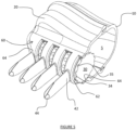
- a hair comb-applicator device 1 in accordance with an embodiment is generally shown in Figures 1 and 2 .
- the comb-applicator device 1 comprises a body formed of interengageable upper 10 and lower 20 housing portions.
- the body encloses a reservoir void 5 which can be filled in use with a hair treatment substance of the user's choice.
- a comb or brush arrangement is provided in the form of at least one row of teeth 40 projecting outwardly from the body.
- a roller 30 is rotatably mounted within the body to transfer hair treatment substance from the reservoir 5 to hair which passes between the teeth 40 of the device 1 during use.
- the body includes a wall 60, formed as part of the lower housing 20, which is specifically shaped and configured to enhance the transfer of hair treatment substance during use.
- the inner surface 64 of the wall 60 generally conforms to the outer surface profile of the roller 30 and may, therefore, have a concave surface shape.
- the inner surface 64 may be considered to define a seat for the roller 30.
- the outer surface 61 of the wall 60 carries the plurality of teeth 40 which project outwardly away from the surface 61.
- the outer surface 61 has a convex shape and including a number of slots 62 extending through the wall and each interposed between the plurality of teeth 40. It may be noted that the slots 62 extend generally circumferentially relative to the underlying roller 30 and extend as a circular arc around the surface of the wall 60.
- the convex shape of the outer surface 61 of the wall 60 acts to guide hair both between the teeth 40 and across the sections of the roller 30 which are exposed by the slots 62 (as discussed in further detail below).
- the housing portions 10, 20, which may for example be injection moulded plastic, form a body which may be considered to have a generally cuboid shape with chamfered or filleted edges. It will be appreciated that the both the overall shape and details of the body may be readily adapted for aesthetic or ergonomic reasons.
- the body is formed with a waisted profile 16 to provide a shape which is readily graspable in use with the body of the device seated in the palm of a user's hand and the teeth extending away from the hand.
- the two housing portions 10, 20 are configured as opposing clamshell portions such that they meet at an interface extending fully around a periphery of the housing. When connected the housing portions define an internal void 5 which provides a reservoir for receiving hair treatment substance.
- the interface between the housing portions 10 and 20 may be a resilient "snap-fit" engagement.
- the housing portions may include complimentary male and female engagement features; for example, one housing portion 10 may include a ridge 12 and the other housing portion 20 may include a corresponding flange 22.
- a resilient sealing member 50 may be provided between the housing portions 10 and 20, for example having a seat on the flange 22, and may be compressed between the housing portions 10 and 20 to provide a leak free interface. Suitable features such as the horn shaped tabs 18 may be provided on one of each of the housing portions 10, 20 to assist the user in pulling apart the housing portions.
- the teeth 40 of the device extend from the wall 60 of the lower housing portion 20.
- the teeth 40 are arranged as a single row wide spaced comb.
- eight teeth 40 are provided and each have a width of around 0.5cm and a spacing between adjacent teeth of approximately 1cm.
- the teeth 40 are blade shaped having a longitudinal length of approximately twice their width and having a generally elliptical cross sectional profile (see for example the view of Figure 2C ) to provide a smooth combing surface in either direction.
- the teeth 40 each extend from a root 42 at the housing wall 60 to a tip 44 distal from the housing. It may be noted that the teeth are each tapered towards the tip 44.
- the teeth 40 are provided in a single generally central row that extend directly away from one side of the device. This enables the device to be arranged in a handle-less configuration with the body shaped to be graspable within the palm of a user. Such an arrangement is particularly useful for combing hair which is more difficult to manage, for example afro or curly hair.
- the body also has a symmetrical profile such that it may be readily used in either a left or right-handed manner.
- the roller 30 is shown in isolation in Figure 3 .
- the roller comprises a central drum 33 having a generally uniform cross-sectional profile and ending at end walls 31.
- Integral pins 32 extend axially outwardly from each end wall 31 to provide a spindle for rotation of the roller relative to the housing 10, 20.
- the spindle pins 32 are received in an opposed pair of recesses 24 formed in the lower housing 20 which seats the roller close to the inner surface 64 of the wall 60 whilst being free to rotate relative to the wall.
- Retaining arms 14 extend downwardly from the upper housing 10 and retain the spindle pins 32 in the recesses 24 when the device 1 is in the assembled configuration. It may be noted that the arms 14 may include a cut out 15 to match the profile of the spindle pin 32.
- roller 30 seats simply in the housing and is captive between the housing portions 10, 20 when the device is assembled. It may, therefore, be appreciated that when the housing portions 10, 20 are separated and the reservoir opened the roller 30 is readily removable from the device. This arrangement may provide a device which can be easily cleaned by the user.
- the drum 33 of the roller 30 has an outer surface including textured portions.
- the textured portions are arranged in a series of bands 34 each aligned with a slot 62 in the wall 60 when the device 1 is assembled.
- a non-textured or smooth sealing surface 36 is provided in the intervening space between adjacent bands 34.
- the sealing surface 36 is, in the assembled configuration, closely positioned next to the inner surface 62 of the wall 60 such that a self-sealing effect may be formed with the hair treatment substance when the roller 30 is stationary.
- the textured bands 34 may be formed as a circumferentially extending rib which is slightly proud of the surface of the drum 33 and may assist in both aligning the textured bands 34 with the slots 62 and with sealing the slot in use.
- Each textured band 34 may be formed of a circumferentially arranged array of projections 35.
- Each projection 35 may for example be generally spheroidal projection extending radially outwardly from the surface of the drum 33, for example the projections may be semi-spheroids.
- the projections may extend from the surface by approximately 2mm and may have a diameter of similar proportions. In the illustrated example, the projections are spaced apart around the circumference of the drum such that a circumferential spacing is provided between adjacent projections 35 which is of similar dimensions to the projections themselves.
- the wall 60 can be considered to have the shape of a longitudinal partial section of a cylinder.
- the cylindrical section is open into the reservoir 5 defined by the housing and the wall 60 is blended into and generally contiguous with the housing portion 20.
- the cylindrical section shape of the wall 60 enables the wall to conform closely to the cylindrical roller 30.
- Such an arrangement both provides a seat for the roller 30 on the inner surface of the wall 64 and ensures that there is a significantly convex curved area of the exterior wall 61 over which hair can be transferred during use of the device.
- the curved extent of the exterior wall 61 enables the slots 62 to extend longitudinally around a circular arc along a portion of the circumferential surface of the roller 30 (and expose a portion of the textured band 34).
- the extend to the cylindrical section formed by the wall may be defined by the central angle of the cylindrical section.
- Figure 6A shows a wall 60 shaped such that the central angle c is an obtuse angle and 6B shows a wall 60' with a central angle of approximately 180 degrees. It may be appreciated that central angles of greater than 180 degrees may mean that the wall 60 overhangs the roller which may provide the disadvantage that the roller cannot be easily removed from the seat (without for example resiliently deforming the housing).
- the central angle of the cylindrical section may defines the curvature and extent to which the wall extends outwards from the body of the device.
- the length of the slot 62 may be extended by using a wall section 60 defined by a cylindrical section with a greater central angle.
- the user separates the two housing portions 10 and 20, using the tab 18 to assist in gripping the upper housing 10.
- the user ensures the roller 30 is positioned in its seat in the lower housing and fills the reservoir 5 with the desired hair treatment substance.
- the housing portions 10, 20 are then snapped together and sealingly engage.
- Grasping the device 1 by the handle portion defined by the housing the row of comb teeth 40 is passed through the hair. As hair passes between the comb teeth 40 it passes over and is guided by the surface of the wall 60. This results in hair frictionally engaging the textured bands 34 of the roller 30 which are aligned with the slots 62.
- the relative movement of the hair and device 1 acts to cause the hair to "drag" circumferentially across the roller 30 and cause rotation of the roller relative to the device 1.
- the device Due to the symmetric profile of the teeth 40, roller 30, wall 60 and slots 62, it does not matter which direction the user chooses to pass hair through the teeth (i.e. the device may be used in a left-handed or right-handed manner). Rotation of the roller enables the portions of the roller facing the reservoir to rotate around into the slots 62 carrying with them hair treatment substance which is then transferred to the hair as the combing action continues.
- the roller 30 is no longer rotating relative to the housing and the tight spacing between the inner surface of the wall 64 and the non-textured surface portions 36 of the drum 33 provides a sealing effect against significant leakage of hair treatment substance from the reservoir 5.
- a roller comprising a generally uniform diameter drum is particularly effective in both providing a good sealing interface and avoiding entanglement of hair in use
- a series of discrete disc elements aligned with each slot could be provided as an alternative.
- Discrete discs could for example be provided with an entirely textured surface profile.
- the disc members of a roller could be rotatably mounted on a common spindle or could be individually rotatably mounted within the housing.
- the slots may be bounded by a sealing wall extending generally radially into the housing with respect to the roller to provide additional sealing of the reservoir.
- the example described above is specifically adapted and optimised for use with Afro hair and associated hair treatment products.
- the skilled person may, therefore, appreciate that the hair comb and applicator device could be adapted for different products and/or hair types in various ways without departing from the present invention.
- the comb arrangement could be changed to use more smaller and more tightly spaced teeth or could be provided with multiple rows of teeth (for example more of a "brush" type arrangement rather than a wide toothed comb).
- the number and dimensions of the slots could be adjusted to help control the application of the substance (for example the rate of application) and to adjust the surface area in contact with the hair.
- the roller could be adjusted with its physical properties having a direct result upon the dynamics of the device in use.
- the roller size may be adjusted and/or the shape and nature of the textured surface may be adapted.
- the textured surface is a series of radial projections the dimensions and number of projections may be adjusted to provide the desired rotational effect.
- the periodicity of the projections around the circumference of the roller may be used to control the rate of rotation of the roller that is resultant from the combing action passing hair across the surface.
- roller Whilst the embodiment described above includes a single roller it will be appreciated that the invention is not limited to such an arrangement. For example, some embodiments may utilise two or more discrete rollers to form the applicator arrangement. For example, separate rollers could be arranged in parallel or coaxially.
Landscapes
- Brushes (AREA)
- Cleaning And Drying Hair (AREA)
Claims (15)
- Haarkamm und Applikatorvorrichtung (1), umfassend:einen Körper (10, 20), der einen Behälter (5) zum Aufnehmen einer Haarbehandlungssubstanz umschließt;eine Vielzahl von Zähnen (40), die in zumindest einer Reihe angeordnet ist; undeine Rolle (30), die drehbar innerhalb des Körpers (10, 20) montiert ist, um Haarbehandlungssubstanz aus dem Behälter (5) auf Haar während Verwendung zu übertragen;wobeider Körper eine Wand (60) beinhaltet, umfassend:eine konkave Innenfläche (64), die einen Sitz für die Rolle bereitstellt;eine konvexe Außenfläche (61), von der sich die Vielzahl von Zähnen (40) erstreckt, und dadurch gekennzeichnet, dasseine Vielzahl von Durchgangsschlitzen (62) in der Wand (60) bereitgestellt ist, wobei die Schlitze zwischen der Vielzahl von Zähnen (40) eingefügt sind und wobei sich jeder Schlitz (62) als Bogen entlang der Wand erstreckt.
- Haarkamm und Applikatorvorrichtung (1) nach Anspruch 1, wobei die Wand (60) als längliches Zylindersegment gebildet ist und sich jeder Schlitz (62) umlaufend um das Zylindersegment erstreckt.
- Haarkamm und Applikatorvorrichtung (1) nach Anspruch 2, wobei die Wand (60) ein längliches Zylindersegment mit einem zentralen Winkel (c) von mehr als 90 Grad definiert und wobei jeder Schlitz (62) optional ein kreisförmiges Segment mit einer Bogenlänge (s) mit einem zentralen Winkel von mehr als 90 Grad ist.
- Haarkamm und Applikatorvorrichtung (1) nach einem der Ansprüche 2 bis 3, wobei sich die Zähne (40) radial nach außen relativ zu dem Zylindersegment erstrecken.
- Haarkamm und Applikatorvorrichtung (1) nach einem vorhergehenden Anspruch, wobei jeder Zahn (40) klingenförmig ist.
- Haarkamm und Applikatorvorrichtung (1) nach Anspruch 5, wobei sich jede Klinge (40) längs von einer Wurzel (42) proximal zu dem Körper (10, 20) zu einer Spitze (44) distal zu dem Körper erstreckt und wobei die Klinge (40) zu der Spitze (44) hin verjüngt ist.
- Haarkamm und Applikatorvorrichtung (1) nach Anspruch 5 oder 6, wobei jede Klinge (40) ein langgestrecktes Querschnittsprofil aufweist und die Längsrichtung des Querschnittes an der Wurzel (42) der Klinge (40) im Allgemeinen mit der Längsrichtung eines benachbarten Schlitzes (62) ausgerichtet ist.
- Haarkamm und Applikatorvorrichtung (1) nach einem der Ansprüche 5 bis 7, wobei die Klingen (40) ein elliptisches Querschnittsprofil aufweisen.
- Haarkamm und Applikatorvorrichtung (1) nach einem vorhergehenden Anspruch, wobei die Rolle (30) einen Radius zwischen ungefähr 1 und 3 cm aufweist.
- Haarkamm und Applikatorvorrichtung (1) nach einem vorhergehenden Anspruch, wobei die Rolle (30) eine zylindrische Trommel (33) umfasst.
- Haarkamm und Applikatorvorrichtung (1) nach einem vorhergehenden Anspruch, wobei die Rolle (30) ein strukturiertes Oberflächenprofil umfasst.
- Haarkamm und Applikatorvorrichtung (1) nach Anspruch 11, wobei das strukturierte Oberflächenprofil in einer Vielzahl von umlaufenden Bändern (34) angeordnet ist, die längs entlang der Rolle (30) beabstandet ist, wobei jedes Band (34) zur Ausrichtung mit einem Schlitz (62) der Wand (60) positioniert ist.
- Haarkamm und Applikatorvorrichtung (1) nach Anspruch 12, wobei das strukturierte Oberflächenprofil eine Vielzahl von radialen Vorsprüngen (35) umfasst, die sich von der Oberfläche der Rolle (30) erstreckt, und wobei jedes Band (34) eine umlaufende Anordnung von Vorsprüngen (35) umfasst.
- Haarkamm und Applikatorvorrichtung (1) nach einem vorhergehenden Anspruch, wobeijedes Ende der Rolle eine Endwand (31) umfasst, von der sich ein längs vorstehendes Stiftelement (32) erstreckt, um eine integrierte Spindel bereitzustellen, unddas Gehäuse (10, 20) ein Paar gegenüberliegende Aussparungen (24) zum Aufnehmen des Stiftelements (32) an jedem Ende der Rolle (30) umfasst.
- Haarkamm und Applikatorvorrichtung (1) nach einem vorhergehenden Anspruch, wobeider Körper einen ersten (10) und einen zweiten (20) elastisch eingreifbaren Gehäuseabschnitt umfasst, undEingriff des ersten (10) und des zweiten (20) Gehäuseabschnittes die Rolle (30) in Position innerhalb des Körpers (10, 20) hält.
Applications Claiming Priority (2)
| Application Number | Priority Date | Filing Date | Title |
|---|---|---|---|
| GB2001335.5A GB2591502B (en) | 2020-01-31 | 2020-01-31 | Hair applicator |
| PCT/EP2021/051537 WO2021151803A1 (en) | 2020-01-31 | 2021-01-22 | Hair comb and applicator device |
Publications (3)
| Publication Number | Publication Date |
|---|---|
| EP4096470A1 EP4096470A1 (de) | 2022-12-07 |
| EP4096470C0 EP4096470C0 (de) | 2024-08-21 |
| EP4096470B1 true EP4096470B1 (de) | 2024-08-21 |
Family
ID=69800190
Family Applications (1)
| Application Number | Title | Priority Date | Filing Date |
|---|---|---|---|
| EP21701782.1A Active EP4096470B1 (de) | 2020-01-31 | 2021-01-22 | Haarkamm und applikatorvorrichtung |
Country Status (7)
| Country | Link |
|---|---|
| US (1) | US12440014B2 (de) |
| EP (1) | EP4096470B1 (de) |
| CN (1) | CN115003190B (de) |
| BR (1) | BR112022014816A2 (de) |
| GB (1) | GB2591502B (de) |
| WO (1) | WO2021151803A1 (de) |
| ZA (1) | ZA202208270B (de) |
Families Citing this family (2)
| Publication number | Priority date | Publication date | Assignee | Title |
|---|---|---|---|---|
| CN115227020B (zh) * | 2021-04-25 | 2023-11-24 | 珠海大拇指创新科技有限公司 | 一种带有附着装置的热风梳 |
| USD1020085S1 (en) * | 2023-05-05 | 2024-03-26 | Temilola Sulu | Detangling comb |
Family Cites Families (19)
| Publication number | Priority date | Publication date | Assignee | Title |
|---|---|---|---|---|
| US2461789A (en) * | 1946-10-04 | 1949-02-15 | Mario G Usai | Hair-treating comb |
| US2758606A (en) * | 1954-08-26 | 1956-08-14 | Mario G Usai | Applicator comb |
| US2865383A (en) * | 1957-11-18 | 1958-12-23 | Kaley Flora Mcdougall | Apparatus for applying lotions, dyes, bleaches or like liquids to the hair roots or to the scalp |
| US4147174A (en) * | 1977-06-22 | 1979-04-03 | Peilet Lester R | Self-cleaning retractable comb |
| US5086793A (en) * | 1990-11-13 | 1992-02-11 | Maybe Holding Co. | Adjustable mascara applicator |
| DE19963065B4 (de) * | 1999-03-06 | 2009-01-22 | Werner Meyer | Vorrichtung zum Auftragen eines Haarbehandlungsmittels und Verwendung der Vorrichtung |
| FR2850257B1 (fr) | 2003-01-23 | 2006-07-14 | Oreal | Applicateur comportant un element d'application permettant d'appliquer un produit, notamment cosmetique et/ou de soin |
| CA2624956A1 (en) * | 2005-10-07 | 2007-04-19 | Lundy Niv | Applicator for hair-treating products |
| ES2525596T3 (es) | 2007-06-27 | 2014-12-26 | Al-Emrani, Mohammad | Método para aplicar un material compuesto reforzado a un miembro estructural |
| FR2933854B1 (fr) * | 2008-07-16 | 2011-08-26 | Oreal | Applicateur pour peigner ou appliquer un produit sur les cils ou les sourcils. |
| US8967156B1 (en) * | 2009-09-11 | 2015-03-03 | Marysia Skidmore | Apparatus and method for selective hair coloring |
| KR101227939B1 (ko) * | 2010-09-30 | 2013-01-30 | 권영억 | 자동염색장치 |
| KR101281518B1 (ko) * | 2011-05-20 | 2013-07-08 | 이재근 | 물길을 열고 닫을 수 있는 염모기 |
| EP2717737B1 (de) * | 2011-06-09 | 2019-08-28 | Anke Wagner | Applikationsvorrichtung und Applikationsverfahren |
| WO2014143035A1 (en) * | 2013-03-15 | 2014-09-18 | Kusin & Kusin, Ltd. | Dry formulation fragrance delivery system |
| US9364068B2 (en) | 2013-09-16 | 2016-06-14 | Kao Corporation | Hair root applicator |
| US9210982B2 (en) | 2014-03-18 | 2015-12-15 | Umm Al-Qura University | Liquid-dispensing comb |
| FR3039372B1 (fr) | 2015-07-29 | 2017-09-08 | Oreal | Dispositif de traitement de la chevelure |
| US20180185675A1 (en) * | 2016-12-15 | 2018-07-05 | Nse Products, Inc. | Device and methods for topical application of fluids to skin |
-
2020
- 2020-01-31 GB GB2001335.5A patent/GB2591502B/en not_active Expired - Fee Related
-
2021
- 2021-01-22 EP EP21701782.1A patent/EP4096470B1/de active Active
- 2021-01-22 WO PCT/EP2021/051537 patent/WO2021151803A1/en not_active Ceased
- 2021-01-22 US US17/795,565 patent/US12440014B2/en active Active
- 2021-01-22 CN CN202180011338.5A patent/CN115003190B/zh active Active
- 2021-01-22 BR BR112022014816A patent/BR112022014816A2/pt unknown
-
2022
- 2022-07-25 ZA ZA2022/08270A patent/ZA202208270B/en unknown
Also Published As
| Publication number | Publication date |
|---|---|
| BR112022014816A2 (pt) | 2022-09-20 |
| US20230088345A1 (en) | 2023-03-23 |
| EP4096470A1 (de) | 2022-12-07 |
| EP4096470C0 (de) | 2024-08-21 |
| CN115003190A (zh) | 2022-09-02 |
| GB2591502A (en) | 2021-08-04 |
| WO2021151803A1 (en) | 2021-08-05 |
| CN115003190B (zh) | 2024-04-09 |
| GB202001335D0 (en) | 2020-03-18 |
| GB2591502B (en) | 2022-04-13 |
| US12440014B2 (en) | 2025-10-14 |
| ZA202208270B (en) | 2024-09-25 |
Similar Documents
| Publication | Publication Date | Title |
|---|---|---|
| JP3583696B2 (ja) | 製品アプリケータ | |
| JP3537133B2 (ja) | 睫毛用の製品アプリケータ、アプリケータセット及び塗布方法 | |
| JP6545792B2 (ja) | 2つの組立部品を備えるアプリケータ部材 | |
| JP3423924B2 (ja) | 睫毛用の製品アプリケータ、アプリケータセット及び塗布方法 | |
| US7992577B2 (en) | Instrument for applying a composition on the eyelashes or eyebrows | |
| US20130233335A1 (en) | Hair treatment accessory | |
| EP4096470B1 (de) | Haarkamm und applikatorvorrichtung | |
| US8920058B2 (en) | Partially extendable hair brush | |
| CA2367346A1 (en) | Applicator brush for liquid or pasty means, especially for decorative cosmetics such as mascara and method for producing same | |
| EP3462977B1 (de) | Kosmetischer applikator mit einer geformten und einer nichtgeformten bürste | |
| US20140107670A1 (en) | Epilator | |
| CN204336137U (zh) | 用于化妆品的涂敷器以及相关的涂敷器组件 | |
| US20210204668A1 (en) | Hand-held hair styling device | |
| CN220876187U (zh) | 涂抹化妆品的涂抹器头 | |
| MX2014005064A (es) | Aplicador cosmetico. | |
| US20080156339A1 (en) | Device for applying cosmetic products or the like to hair | |
| US20060174910A1 (en) | Inter dental tooth cleaner and delivery device | |
| ES2969579T3 (es) | Pincel de aplicación de un producto cosmético, procedimiento relacionado y kit | |
| US11974645B2 (en) | Device and method for coiling hair | |
| US20160045014A1 (en) | Cosmetic applicator | |
| JP5346887B2 (ja) | 化粧料塗布具 | |
| JP2020522283A (ja) | 手持ち式ヘアスタイリングデバイス | |
| EP4520222A1 (de) | Applikatorkopf zum auftragen eines kosmetischen produkts | |
| JP6608222B2 (ja) | 毛髪化粧料塗布具 | |
| RU2778431C1 (ru) | Щеточка-аппликатор туши для ресниц |
Legal Events
| Date | Code | Title | Description |
|---|---|---|---|
| STAA | Information on the status of an ep patent application or granted ep patent |
Free format text: STATUS: UNKNOWN |
|
| STAA | Information on the status of an ep patent application or granted ep patent |
Free format text: STATUS: THE INTERNATIONAL PUBLICATION HAS BEEN MADE |
|
| PUAI | Public reference made under article 153(3) epc to a published international application that has entered the european phase |
Free format text: ORIGINAL CODE: 0009012 |
|
| STAA | Information on the status of an ep patent application or granted ep patent |
Free format text: STATUS: REQUEST FOR EXAMINATION WAS MADE |
|
| 17P | Request for examination filed |
Effective date: 20220803 |
|
| AK | Designated contracting states |
Kind code of ref document: A1 Designated state(s): AL AT BE BG CH CY CZ DE DK EE ES FI FR GB GR HR HU IE IS IT LI LT LU LV MC MK MT NL NO PL PT RO RS SE SI SK SM TR |
|
| DAX | Request for extension of the european patent (deleted) | ||
| RAV | Requested validation state of the european patent: fee paid |
Extension state: TN Effective date: 20220803 Extension state: MA Effective date: 20220803 |
|
| GRAP | Despatch of communication of intention to grant a patent |
Free format text: ORIGINAL CODE: EPIDOSNIGR1 |
|
| STAA | Information on the status of an ep patent application or granted ep patent |
Free format text: STATUS: GRANT OF PATENT IS INTENDED |
|
| RIC1 | Information provided on ipc code assigned before grant |
Ipc: A46B 11/00 20060101ALI20230502BHEP Ipc: A45D 24/24 20060101ALI20230502BHEP Ipc: A45D 24/22 20060101AFI20230502BHEP |
|
| INTG | Intention to grant announced |
Effective date: 20230607 |
|
| GRAJ | Information related to disapproval of communication of intention to grant by the applicant or resumption of examination proceedings by the epo deleted |
Free format text: ORIGINAL CODE: EPIDOSDIGR1 |
|
| STAA | Information on the status of an ep patent application or granted ep patent |
Free format text: STATUS: REQUEST FOR EXAMINATION WAS MADE |
|
| GRAP | Despatch of communication of intention to grant a patent |
Free format text: ORIGINAL CODE: EPIDOSNIGR1 |
|
| STAA | Information on the status of an ep patent application or granted ep patent |
Free format text: STATUS: GRANT OF PATENT IS INTENDED |
|
| INTC | Intention to grant announced (deleted) | ||
| INTG | Intention to grant announced |
Effective date: 20231102 |
|
| GRAS | Grant fee paid |
Free format text: ORIGINAL CODE: EPIDOSNIGR3 |
|
| GRAA | (expected) grant |
Free format text: ORIGINAL CODE: 0009210 |
|
| STAA | Information on the status of an ep patent application or granted ep patent |
Free format text: STATUS: THE PATENT HAS BEEN GRANTED |
|
| AK | Designated contracting states |
Kind code of ref document: B1 Designated state(s): AL AT BE BG CH CY CZ DE DK EE ES FI FR GB GR HR HU IE IS IT LI LT LU LV MC MK MT NL NO PL PT RO RS SE SI SK SM TR |
|
| REG | Reference to a national code |
Ref country code: GB Ref legal event code: FG4D |
|
| REG | Reference to a national code |
Ref country code: CH Ref legal event code: EP |
|
| REG | Reference to a national code |
Ref country code: IE Ref legal event code: FG4D |
|
| REG | Reference to a national code |
Ref country code: DE Ref legal event code: R096 Ref document number: 602021017492 Country of ref document: DE |
|
| U01 | Request for unitary effect filed |
Effective date: 20240918 |
|
| REG | Reference to a national code |
Ref country code: CH Ref legal event code: PK Free format text: BERICHTIGUNGEN |
|
| RIN2 | Information on inventor provided after grant (corrected) |
Inventor name: MOUHAMAD, YOUMNA |
|
| U07 | Unitary effect registered |
Designated state(s): AT BE BG DE DK EE FI FR IT LT LU LV MT NL PT RO SE SI Effective date: 20241016 |
|
| PG25 | Lapsed in a contracting state [announced via postgrant information from national office to epo] |
Ref country code: NO Free format text: LAPSE BECAUSE OF FAILURE TO SUBMIT A TRANSLATION OF THE DESCRIPTION OR TO PAY THE FEE WITHIN THE PRESCRIBED TIME-LIMIT Effective date: 20241121 |
|
| PG25 | Lapsed in a contracting state [announced via postgrant information from national office to epo] |
Ref country code: GR Free format text: LAPSE BECAUSE OF FAILURE TO SUBMIT A TRANSLATION OF THE DESCRIPTION OR TO PAY THE FEE WITHIN THE PRESCRIBED TIME-LIMIT Effective date: 20241122 Ref country code: PL Free format text: LAPSE BECAUSE OF FAILURE TO SUBMIT A TRANSLATION OF THE DESCRIPTION OR TO PAY THE FEE WITHIN THE PRESCRIBED TIME-LIMIT Effective date: 20240821 |
|
| PG25 | Lapsed in a contracting state [announced via postgrant information from national office to epo] |
Ref country code: IS Free format text: LAPSE BECAUSE OF FAILURE TO SUBMIT A TRANSLATION OF THE DESCRIPTION OR TO PAY THE FEE WITHIN THE PRESCRIBED TIME-LIMIT Effective date: 20241221 |
|
| PG25 | Lapsed in a contracting state [announced via postgrant information from national office to epo] |
Ref country code: HR Free format text: LAPSE BECAUSE OF FAILURE TO SUBMIT A TRANSLATION OF THE DESCRIPTION OR TO PAY THE FEE WITHIN THE PRESCRIBED TIME-LIMIT Effective date: 20240821 |
|
| PG25 | Lapsed in a contracting state [announced via postgrant information from national office to epo] |
Ref country code: ES Free format text: LAPSE BECAUSE OF FAILURE TO SUBMIT A TRANSLATION OF THE DESCRIPTION OR TO PAY THE FEE WITHIN THE PRESCRIBED TIME-LIMIT Effective date: 20240821 Ref country code: RS Free format text: LAPSE BECAUSE OF FAILURE TO SUBMIT A TRANSLATION OF THE DESCRIPTION OR TO PAY THE FEE WITHIN THE PRESCRIBED TIME-LIMIT Effective date: 20241121 |
|
| PG25 | Lapsed in a contracting state [announced via postgrant information from national office to epo] |
Ref country code: RS Free format text: LAPSE BECAUSE OF FAILURE TO SUBMIT A TRANSLATION OF THE DESCRIPTION OR TO PAY THE FEE WITHIN THE PRESCRIBED TIME-LIMIT Effective date: 20241121 Ref country code: PL Free format text: LAPSE BECAUSE OF FAILURE TO SUBMIT A TRANSLATION OF THE DESCRIPTION OR TO PAY THE FEE WITHIN THE PRESCRIBED TIME-LIMIT Effective date: 20240821 Ref country code: NO Free format text: LAPSE BECAUSE OF FAILURE TO SUBMIT A TRANSLATION OF THE DESCRIPTION OR TO PAY THE FEE WITHIN THE PRESCRIBED TIME-LIMIT Effective date: 20241121 Ref country code: IS Free format text: LAPSE BECAUSE OF FAILURE TO SUBMIT A TRANSLATION OF THE DESCRIPTION OR TO PAY THE FEE WITHIN THE PRESCRIBED TIME-LIMIT Effective date: 20241221 Ref country code: HR Free format text: LAPSE BECAUSE OF FAILURE TO SUBMIT A TRANSLATION OF THE DESCRIPTION OR TO PAY THE FEE WITHIN THE PRESCRIBED TIME-LIMIT Effective date: 20240821 Ref country code: GR Free format text: LAPSE BECAUSE OF FAILURE TO SUBMIT A TRANSLATION OF THE DESCRIPTION OR TO PAY THE FEE WITHIN THE PRESCRIBED TIME-LIMIT Effective date: 20241122 Ref country code: ES Free format text: LAPSE BECAUSE OF FAILURE TO SUBMIT A TRANSLATION OF THE DESCRIPTION OR TO PAY THE FEE WITHIN THE PRESCRIBED TIME-LIMIT Effective date: 20240821 |
|
| PG25 | Lapsed in a contracting state [announced via postgrant information from national office to epo] |
Ref country code: SM Free format text: LAPSE BECAUSE OF FAILURE TO SUBMIT A TRANSLATION OF THE DESCRIPTION OR TO PAY THE FEE WITHIN THE PRESCRIBED TIME-LIMIT Effective date: 20240821 |
|
| PG25 | Lapsed in a contracting state [announced via postgrant information from national office to epo] |
Ref country code: CZ Free format text: LAPSE BECAUSE OF FAILURE TO SUBMIT A TRANSLATION OF THE DESCRIPTION OR TO PAY THE FEE WITHIN THE PRESCRIBED TIME-LIMIT Effective date: 20240821 |
|
| PG25 | Lapsed in a contracting state [announced via postgrant information from national office to epo] |
Ref country code: SK Free format text: LAPSE BECAUSE OF FAILURE TO SUBMIT A TRANSLATION OF THE DESCRIPTION OR TO PAY THE FEE WITHIN THE PRESCRIBED TIME-LIMIT Effective date: 20240821 |
|
| PLBE | No opposition filed within time limit |
Free format text: ORIGINAL CODE: 0009261 |
|
| STAA | Information on the status of an ep patent application or granted ep patent |
Free format text: STATUS: NO OPPOSITION FILED WITHIN TIME LIMIT |
|
| PGFP | Annual fee paid to national office [announced via postgrant information from national office to epo] |
Ref country code: GB Payment date: 20250626 Year of fee payment: 5 |
|
| 26N | No opposition filed |
Effective date: 20250522 |
|
| U21 | Renewal fee for the european patent with unitary effect paid with additional fee |
Year of fee payment: 5 Effective date: 20250626 |
|
| REG | Reference to a national code |
Ref country code: CH Ref legal event code: PL |
|
| PG25 | Lapsed in a contracting state [announced via postgrant information from national office to epo] |
Ref country code: MC Free format text: LAPSE BECAUSE OF FAILURE TO SUBMIT A TRANSLATION OF THE DESCRIPTION OR TO PAY THE FEE WITHIN THE PRESCRIBED TIME-LIMIT Effective date: 20240821 |
|
| PG25 | Lapsed in a contracting state [announced via postgrant information from national office to epo] |
Ref country code: CH Free format text: LAPSE BECAUSE OF NON-PAYMENT OF DUE FEES Effective date: 20250131 |
|
| PG25 | Lapsed in a contracting state [announced via postgrant information from national office to epo] |
Ref country code: IE Free format text: LAPSE BECAUSE OF NON-PAYMENT OF DUE FEES Effective date: 20250122 |