EP4094692B1 - System und verfahren zur bildgebung eines subjekts - Google Patents
System und verfahren zur bildgebung eines subjekts Download PDFInfo
- Publication number
- EP4094692B1 EP4094692B1 EP22174498.0A EP22174498A EP4094692B1 EP 4094692 B1 EP4094692 B1 EP 4094692B1 EP 22174498 A EP22174498 A EP 22174498A EP 4094692 B1 EP4094692 B1 EP 4094692B1
- Authority
- EP
- European Patent Office
- Prior art keywords
- ray
- subject
- detector
- imaging system
- time
- Prior art date
- Legal status (The legal status is an assumption and is not a legal conclusion. Google has not performed a legal analysis and makes no representation as to the accuracy of the status listed.)
- Active
Links
Images


Classifications
-
- A—HUMAN NECESSITIES
- A61—MEDICAL OR VETERINARY SCIENCE; HYGIENE
- A61B—DIAGNOSIS; SURGERY; IDENTIFICATION
- A61B6/00—Apparatus or devices for radiation diagnosis; Apparatus or devices for radiation diagnosis combined with radiation therapy equipment
- A61B6/40—Arrangements for generating radiation specially adapted for radiation diagnosis
-
- A—HUMAN NECESSITIES
- A61—MEDICAL OR VETERINARY SCIENCE; HYGIENE
- A61B—DIAGNOSIS; SURGERY; IDENTIFICATION
- A61B6/00—Apparatus or devices for radiation diagnosis; Apparatus or devices for radiation diagnosis combined with radiation therapy equipment
- A61B6/52—Devices using data or image processing specially adapted for radiation diagnosis
- A61B6/5211—Devices using data or image processing specially adapted for radiation diagnosis involving processing of medical diagnostic data
-
- A—HUMAN NECESSITIES
- A61—MEDICAL OR VETERINARY SCIENCE; HYGIENE
- A61B—DIAGNOSIS; SURGERY; IDENTIFICATION
- A61B6/00—Apparatus or devices for radiation diagnosis; Apparatus or devices for radiation diagnosis combined with radiation therapy equipment
- A61B6/42—Arrangements for detecting radiation specially adapted for radiation diagnosis
-
- A—HUMAN NECESSITIES
- A61—MEDICAL OR VETERINARY SCIENCE; HYGIENE
- A61B—DIAGNOSIS; SURGERY; IDENTIFICATION
- A61B6/00—Apparatus or devices for radiation diagnosis; Apparatus or devices for radiation diagnosis combined with radiation therapy equipment
- A61B6/48—Diagnostic techniques
- A61B6/488—Diagnostic techniques involving pre-scan acquisition
-
- A—HUMAN NECESSITIES
- A61—MEDICAL OR VETERINARY SCIENCE; HYGIENE
- A61B—DIAGNOSIS; SURGERY; IDENTIFICATION
- A61B6/00—Apparatus or devices for radiation diagnosis; Apparatus or devices for radiation diagnosis combined with radiation therapy equipment
- A61B6/50—Apparatus or devices for radiation diagnosis; Apparatus or devices for radiation diagnosis combined with radiation therapy equipment specially adapted for specific body parts; specially adapted for specific clinical applications
- A61B6/502—Apparatus or devices for radiation diagnosis; Apparatus or devices for radiation diagnosis combined with radiation therapy equipment specially adapted for specific body parts; specially adapted for specific clinical applications for diagnosis of breast, i.e. mammography
-
- A—HUMAN NECESSITIES
- A61—MEDICAL OR VETERINARY SCIENCE; HYGIENE
- A61B—DIAGNOSIS; SURGERY; IDENTIFICATION
- A61B6/00—Apparatus or devices for radiation diagnosis; Apparatus or devices for radiation diagnosis combined with radiation therapy equipment
- A61B6/52—Devices using data or image processing specially adapted for radiation diagnosis
- A61B6/5258—Devices using data or image processing specially adapted for radiation diagnosis involving detection or reduction of artifacts or noise
-
- A—HUMAN NECESSITIES
- A61—MEDICAL OR VETERINARY SCIENCE; HYGIENE
- A61B—DIAGNOSIS; SURGERY; IDENTIFICATION
- A61B6/00—Apparatus or devices for radiation diagnosis; Apparatus or devices for radiation diagnosis combined with radiation therapy equipment
- A61B6/52—Devices using data or image processing specially adapted for radiation diagnosis
- A61B6/5294—Devices using data or image processing specially adapted for radiation diagnosis involving using additional data, e.g. patient information, image labeling, acquisition parameters
-
- A—HUMAN NECESSITIES
- A61—MEDICAL OR VETERINARY SCIENCE; HYGIENE
- A61B—DIAGNOSIS; SURGERY; IDENTIFICATION
- A61B6/00—Apparatus or devices for radiation diagnosis; Apparatus or devices for radiation diagnosis combined with radiation therapy equipment
- A61B6/54—Control of apparatus or devices for radiation diagnosis
- A61B6/545—Control of apparatus or devices for radiation diagnosis involving automatic set-up of acquisition parameters
-
- A—HUMAN NECESSITIES
- A61—MEDICAL OR VETERINARY SCIENCE; HYGIENE
- A61B—DIAGNOSIS; SURGERY; IDENTIFICATION
- A61B6/00—Apparatus or devices for radiation diagnosis; Apparatus or devices for radiation diagnosis combined with radiation therapy equipment
- A61B6/58—Testing, adjusting or calibrating thereof
- A61B6/582—Calibration
Definitions
- the field of the disclosure relates generally to medical technologies, and more particularly, to a system and method for imaging a subject.
- Non-invasive imaging technologies allow images of the internal structures or features of a patient or a subject to be obtained without performing an invasive procedure on the patient or the subject.
- such non-invasive imaging technologies rely on various physical principles, such as the differential transmission of X-rays through the target volume or the reflection of acoustic waves, to acquire data and to construct images or otherwise represent the observed internal features of the patient or the subject.
- X-ray radiation is directed toward a subject, typically a patient in a medical diagnostic application, a package or baggage in a security screening application, or a fabricated component in an industrial quality control or inspection application.
- a portion of the radiation impacts a detector where the image data is collected.
- a detector In digital X-ray systems, a detector generates digital signals representative of the amount or intensity of radiation impacting discrete pixel regions of the detector surface. The signals may then be processed to generate an image that may be displayed for review.
- a detector array including a series of detector elements, produces similar signals through various positions as one or both of the source and detector are displaced around the imaged volume, allowing data to be acquired over a limited or complete angular range.
- US 20190209117A1 describes a method, apparatus, system, and computer program product for automatically determining exposure time for an intraoral image.
- the method includes acquiring a low dose pilot projection image of an object to be imaged, performing a sanity check to ensure that a usable exposure is attainable, estimating a remaining exposure time required for an additional projection image, taking the additional projection image and adding the two images together to generate a final image wherein the dose delivered to the x-ray detector is influenced by patient specific dental anatomy.
- the medical imaging system includes an X-ray source for transmitting X-rays through a subject and a detector to receive the X-ray energy of the X-rays after having passed through the subject.
- the medical imaging system further includes a processing system programmed to generate a pre-shot image of the subject using low energy X-ray intensity from the X-ray source and to determine a plurality of acquisition parameters for a main scan of the subject based on the pre-shot image.
- the processing system is also configured to determine a saturation time of the detector for the corresponding acquisition parameters based on detector calibration data and to determine a number of time frames required to reach the targeted dose based on the saturation time.
- the processing system is programmed to apply an X-ray dosage level of the subject using the X-ray source based on the number of time frames and to generate the image of the subject based on the detected X-ray energy at the X-ray detector for the applied X-ray dosage level.
- a method for imaging a subject includes providing an X-ray source for transmitting X-rays through a subject and providing a detector operative to receive the X-ray energy of the X-rays after having passed through the subject.
- the method further includes generating a pre-shot image of a subject using low energy X-ray intensity from the X-ray source and determining a plurality of acquisition parameters for a main scan of the subj ect based on the pre-shot image.
- the method also includes determining a saturation time of the detector for the corresponding acquisition parameters based on detector calibration data and determining a number of time frames required to reach the targeted dose based on the saturation time.
- the method includes applying an X-ray dosage level of the subject using the X-ray source based on the number of time frames and generating the image of the subject based on the detected X-ray energy at the X-ray detector for the applied X-ray dosage level.
- circuit and “circuitry” and “controller” may include either a single component or a plurality of components, which are either active and/or passive and are connected or otherwise coupled together to provide the described function.
- the present approaches relate to automatic exposure control (AEC) used in an X-ray imaging system.
- AEC automatic exposure control
- the AEC Based on a low exposure image (also referred to as pre-shot image), the AEC computes the acquisition parameters for the main acquisition that are needed to reach the required image quality.
- the pre-shot may be a low resolution two-dimensional ("2D") image acquired via a lower X-ray dose compared to subsequent X-ray dose that is used for obtaining images of the patient and used to make a medical diagnosis.
- the pre-shot image is also used to predict X-ray time for the main acquisition.
- an additional parameter which is a number of time frames required to reach the targeted X-ray dose without saturating the detector is determined.
- the addition of the acquired time frames gives the resulting unsaturated image of the subject.
- a subject is a human (or patient), an animal, or a phantom.
- an example of an X-ray based imaging system 10 suitable for acquiring X-ray attenuation data for image reconstruction as discussed herein is provided in FIG. 1 .
- the imaging system 10 operates so as to improve the dynamic range of the detector panel 14.
- the detector 14 may be fabricated using complementary metal-oxide semiconductor (CMOS) materials and techniques so as to incorporate active pixels on the detector array.
- CMOS complementary metal-oxide semiconductor
- active pixels include amplification circuitry (e.g., an amplifier) within the respective pixel circuits themselves (as opposed to downstream and separate from the detector array) and are suitable for non-destructive readout during an imaging session.
- CMOS-based detectors are discussed in certain examples herein, it should be appreciated that the present approaches may be more generally applied to any detector capable of non-destructive readout operations, regardless of whether the fabrication of the detector utilizes CMOS components or other. Further in certain implementations the CMOS-based detector 14 is fabricated using crystalline silicon (c-Si) or amorphous silicon (a-Si).
- imaging system 10 includes a source of X-ray radiation 12 along with the detector 14.
- the X-ray source 12 may be an X-ray tube, a distributed X-ray source (such as a solid-state or thermionic X-ray source) or any other source of X-ray radiation suitable for the acquisition of medical or other images.
- the X-rays 16 generated by the source 12 pass into a region in which a patient 18 (or an object or other subject to be imaged), is positioned during a procedure.
- a portion of the X-ray radiation 20 passes through or around the patient 18 (or other subject of interest) and impacts a detector array, represented generally as the detector 14.
- detector elements i.e., pixels
- detector elements i.e., pixels
- These signals are acquired and processed, as discussed herein, to reconstruct images of the features within the patient 18 or imaged object of interest.
- one or both of the source 12 or detector 14 may be moved (e.g., rotated and/or linearly translated) relative to the patient or imaged object along or about one or more axes during an examination procedure during which projection data is acquired.
- the source 12 and/or detector 14 may move about one or more axes of rotation so as to facilitate acquisition of projection data at a variety of different radial views with respect to the imaged volume.
- imager motion may be supplemented by motion of the underlying patient support (e.g., table) to achieve complex imaging trajectories with respect to the relative position and motion between the imager and patient over time.
- the translation and rotation of the imager components may be determined or coordinated in accordance with a specified protocol.
- the movement of the imager components may be initiated and/or controlled by one or more linear/rotational subsystems 46.
- the linear/rotational subsystems 46 may include support structures, motors, gears, bearings, and the like, that enable the rotational and/or translational movement of the imager components.
- the linear/rotational subsystems 46 may include a structural apparatus (e.g., a C-arm apparatus having rotational movement about at least two axes, a gantry, and so forth) supporting the source and detector 12, 14.
- a suitable system 10 may include a system controller 48 to coordinate and control the imaging components.
- a system controller may include one or more of an X-ray controller 50 for controlling operation of source 12, a motor controller 52 for controlling motion of movable subsystems, and a data acquisition system (DAS) 54 for handling signal readout of the detector 14.
- DAS data acquisition system
- the system controller 48 may incorporate one or more processing devices that include or communicate with tangible, non-transitory, machine readable media collectively storing instructions executable by the one or more processors to perform the operations described herein.
- the X-ray controller 50, the motor controller 52, and the data acquisition systems 54 may share one or more processing components 56 that are each specifically configured to cooperate with one or more memory devices 58 storing instructions that, when executed by the processing components 56, perform the image acquisition and reconstruction techniques described herein. Further, the processing components 56 and the memory components 58 may coordinate in order to perform the various image reconstruction processes.
- the system controller 48 and the various circuitry that it includes, as well as the processing and memory components 56, 58, may be accessed or otherwise controlled by an operator via an operator workstation 60.
- the operator workstation 60 may be communicatively coupled to a printer 62 for printing images, patient data, and the like.
- the operator workstation 60 may also be in communication with a display 64 that enables the operator to view various parameters in real time, to view images produced by the acquired data, and the like.
- the operator workstation 60 may also, in certain embodiments, be communicatively coupled to a picture archiving and communication system (PACS) 66, which may allow images to be shared with other facilities, for example, a remote client 68.
- PACS picture archiving and communication system
- the imaging system 10, which may include a detector 14 may be used in imaging processes that address various dynamic range issues that arise in certain imaging contexts. For example, in certain circumstances one or more pixels of the detector 14 may become saturated during an exposure event.
- FIGS. 2 and 3 an example of such a saturation event is provided in the context of a mammography scan. In this example, a single time frame acquisition (i.e., a scan in which a single read event of the detector 14 is performed) is depicted.
- a breast 92 to be imaged is compressed between a compression plate 94 and the detector 14 such that a portion 96 of the breast 92 is at a uniform thickness.
- a portion of 98 the breast 92 is compressed to a thinner, typically non-uniform, thickness due to the amount of tissue present.
- a third imaging region 100 is devoid of intervening breast tissue and is exposed to unattenuated X-rays during a scan.
- each pixel 90 corresponds to a respective region 96, 98, or 100 having different X-ray exposure characteristics.
- pixel 90c underlying the thick breast tissue region 96 receives the most attenuated X-rays and is unlikely to saturate over the exposure time (x-axis), as shown by charge accumulation line 110 and saturation threshold 108 of FIG. 3 .
- pixel 90a is positioned outside the boundary of the breast tissue 92 and is fully exposed to the unattenuated X-ray radiation. As a result, the pixel 90a saturates much earlier than do those pixels underneath tissue.
- pixel 90b is schematically illustrated as being positioned in the vicinity of the skin line (i.e., at the tissue boundary), such that the radiation incident on the pixel 90b is partially attenuated compared to that incident on pixel 90c. That is, the X-rays incident on pixel 90b pass through some portion of tissue, and so are not unattenuated, but, as shown by charge accumulation line 114 of FIG. 2 , in the scan interval associated with a single time frame read (indicated as readout 132, shown by dotted), the pixel 90b becomes saturated before the scan in completed and the pixel 90b is readout. As a result, valuable information is lost at the boundary of the imaged tissue (i.e., the skin line).
- FIGS. 5 and 6 One approach to address saturation issues for regions where the tissue is of non-uniform thickness and where attenuation is less than what is seen for thicker tissue regions being imaged is described with reference to FIGS. 5 and 6 .
- multiple destructive (i.e., charge depleting) readout operations are performed over the course of a single scan exposure. This is graphically illustrated in FIG. 5 , where an exposure event 130 occurs over a time t. Over the course of the exposure 130, multiple destructive readout operations 132 (also referred to as multiple time frames) are performed, with readout events generally timed so as to avoid saturation of pixels in those areas of the detector panel underlying tissue regions where uniform thickness cannot be achieved (e.g., near the tissue boundary within the image and so forth).
- Each readout operation 132 or time frame generates attenuation data that can be reconstructed into a separate image 136.
- Some or all of the multiple images 136 can be combined or summed to generate a final image 140 with reduced skin line artifacts.
- some or all of the multiple images may be used in an estimation process 144 in which various image parameters (e.g., the skin line boundary, electronic noise, signal-to-noise, optimized pixel intensity) are estimated and used to generate a final or diagnostic image.
- the skin line boundary (dotted line 142) may be estimated and the final image may include pixels populated with intensity data up to the boundary so as to minimize data loss at the boundary region.
- FIG. 6 a graphical representation of pixel charge accumulation for such a multi-frame embodiment is shown which is similar to the graphical representation of FIG. 3 and which is based on the pixel arrangement shown in FIG. 2 .
- pixel 90c underlying the thick breast tissue region 96 receives the most attenuated X-rays and does not saturate between readout events132, as shown by charge accumulation lines 110 and sensor saturation threshold 150.
- Pixel 90a is positioned outside the boundary of the breast tissue 92 and is fully exposed to the unattenuated X-ray radiation. As a result, the pixel 90a saturates much earlier than do those pixels underneath tissue, even in this multi-frame scenario.
- Pixel 90b is schematically illustrated as being positioned in the vicinity of the skin line (i.e., at the tissue boundary), such that the radiation incident on the pixel 90b is partially attenuated compared to that incident on pixel 90c.
- charge accumulation lines 114 of FIG. 6 in the scan intervals associated with multiple readout events 132, the pixel 90b approaches saturation but, even if saturation is reached, does not spend substantial time in the elapsed state before being readout and the charge cleared.
- attenuation information is generally not lost at the boundary of the imaged tissue (i.e., the skin line) or in the regions where the tissue thickness is less than the uniformly compressed regions.
- the depicted example is idealized and, in practice, the charge accumulation lines 114 may reflect that the readout events occur prior to the pixel 90b reaching saturation threshold 150 or, alternatively, some minimal amount of time may be spent in a saturated state before readout for these pixels 90b.
- the summing or estimation processes employed to construct final image 140 from the multiple images 136 may reflect a generally expanded or extended dynamic range for the detector 14.
- an automatic exposure control (AEC) algorithm is used to generate relevant acquisition parameters needed for main scan of the patient.
- the main scan event here refers to the image acquisition of the patient based on which the patient disorder diagnosis is determined.
- the AEC algorithm controls the X-ray exposure per image and helps avoid saturation of the detector 14 and may be implemented in X-ray controller 50 of Fig. 1 .
- the preferred embodiment of the AEC algorithm utilizes a pre-shot image from detector 14. The pre-shot image is obtained from a small dose of X-rays occurring before the main X-ray exposure that results in an image of a patient. A plurality of acquisition parameters is then determined from the pre-shot image.
- the plurality of acquisition parameters includes X-ray tube current, X-ray tube voltage, targeted X-ray dose etc.
- An additional parameter- saturation time of the detector is determined using a calibration method. Based on the plurality of acquisition parameters and the saturation time of the detector, a number of time frames or scan events required to reach the targeted dose without saturating the detector are determined.
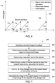
- Fig. 7 shows a flow chart 200 of a method for imaging a subject in accordance with an embodiment of the present technique.
- the method includes acquiring a pre-shot image of the subject in step 202.
- the pre-shot image is obtained from a small dose of X-rays before the main X-ray exposure of the subject that results in an image of the subject obtained for diagnosis.
- the method includes determining a plurality of acquisition parameters based on the pre-shot image.
- the plurality of acquisition parameters includes X-ray tube current, X-ray tube voltage, and targeted X-ray dose of the detector among others.
- determining the acquisition parameter may be based on configuration settings determined while taking the pre-shot image such as one of an anode material of the X-ray source, a peak kilovoltage ("kVp") of the X-ray source, a milliamperes ("mA") per pulse of the X-ray source, i.e., the integral of a current flowing through a ray tube/generator of the source during a pulse which may be in milliampere-seconds ("mAs").
- configuration settings determined while taking the pre-shot image such as one of an anode material of the X-ray source, a peak kilovoltage ("kVp") of the X-ray source, a milliamperes ("mA”) per pulse of the X-ray source, i.e., the integral of a current flowing through a ray tube/generator of the source during a pulse which may be in milliampere-seconds (“mAs").
- the acquisition parameters may be derived from the configuration settings via one or more models, e.g., a look up table containing values for anode material, filter selection, kVp, mAs per pulse and/or time.
- models e.g., a look up table containing values for anode material, filter selection, kVp, mAs per pulse and/or time.
- a saturation time for the detector corresponding to the plurality of acquisition parameters is determined based on detector calibration data.
- the detector calibration data obtained by pre-calibrated the detector in advance of the main scan of the subject.
- the naked detector 14 i.e., without the subject to be scanned
- the naked detector 14 is illuminated by the X-ray source 12 in every possible configuration setting of X-ray system 10.
- the time at which the detector saturates is determined.
- the saturation time may be determined by dividing the saturation scan total exposure by the saturation scan tube current.
- a number of time frames or scan events required to reach the targeted dose without saturating the detector are determined in step 206.
- the method includes applying an X-ray dosage level of the subject based on the number of time frames.
- the X-ray dosage level is applied by X-ray source 12 based on the X-ray controller commands which provides the number of time frames.
- the image of the subject is generated based on the detected X-ray energy for the applied X-ray dosage level.
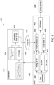
- Fig. 8 shows a schematic diagram 300 of a portion of imaging system 10 of Fig. 1 .
- the portion 300 is part of the X-ray controller 50 of Fig. 1 .
- X-ray controller 50 includes a calibration module 302 and an AEC acquisition module 304.
- the term "module” refers to software, hardware, or firmware, or any combination of these, or any system, process, or functionality that performs or facilitates the processes described herein.
- the calibration module 302 illuminates the naked detector 14 (i.e., without the subject to be scanned) by the X-ray source 12 in every possible configuration of these three settings. In another embodiment, instead of illuminating the naked detector in every possible configuration, only a few configuration points are considered and an interpolation from only those points of measure is considered.
- the AEC spectrum 304 of all these configuration points is provided to calibration module 302 as an input.
- Calibration module 302 determines a saturation time 308 of the detector 14 for each of the configuration settings (kV, track, filter). In one embodiment, to determines the saturation time 308, calibration module 302 first measures the saturation scan total exposure (mAs) 310 which is the X-ray exposure at which the detector saturates for the given configuration setting. Thereafter, the calibration module 302 measures the saturation scan tube current (mA) 312 that was applied and then based on the tube current mA and the saturation scan total exposure the saturation time 308 is determined. In one embodiment the saturation time 308 may be determined by dividing saturation scan total exposure by the saturation scan tube current (i.e., mAs/mA). Thus, saturation times for various configuration settings of the X-ray system 10 are stored in a look up table by the calibration module 302.
- the AEC module 304 first acquires a pre-shot or pre-exposure image 314 which is used to measure the attenuation property of the subject.
- the attenuation property is polymethyl methacrylate-equivalent thickness at densest location of the subject.
- the pre-shot image is generated based on low energy X-ray intensity exposure of the subject from the X-ray source. It should be noted here that the low energy X-ray intensity here refers to the X-ray intensity which has a lower value compared to the X-ray intensity used for main scan of the subject.
- Attenuation properties X-ray radiation is being attenuated (i.e., attenuation properties) by the subject.
- the spectrum values 316, tube current 318 and total exposure 320 for the main scan can be determined.
- Spectrum values 316 includes configuration settings (kV, track, filter) for the main scan.
- AEC module 304 then provides the configuration settings 306 to the calibration module 302, which determines saturation time 308 from the look up table corresponding to the configuration settings 306.
- main scan total exposure (mAs) 320 and main scan tube current (mA) 318 are also determined from the attenuation properties of the subject.
- main scan X-ray time 322 is determined based on the main scan tube current 318 and the main scan total exposure 320.
- the main scan X-ray time 322 may be determined by dividing main scan total exposure 320 value by the main scan tube current 318 value.
- AEC module 304 further determines a time frame 324 by subtracting a buffer time 326 from the saturation time 308 corresponding to the same configuration as that of main scan configuration. The buffer time 326 is used to provide some extra time margin to integrate the whole signal from the main x-ray acquisition.
- a number of time frames 328 required for main scan acquisition are determined based on time frame 324 and X-ray time 322.
- the number of time frames 328 may be determined by dividing X-ray time 322 by time frame 324.
- the plurality of time frames as determined by the number 328 are then used to apply X-ray dosage level of the subject using the X-ray source 330 for acquiring the main scan and to generate the image of the subject for disorder diagnosis.
- Fig. 9 shows a schematic diagram 400 of an example time frame calculation system of Fig. 8 .
- main scan configuration settings 410 are provided to calibration module 412 which determines that for given X-ray tube current 414 (60 mA), the detector X-ray saturation exposure 416 occurs at 7.2 mAs. Thus, based on X-ray tube current 414 and X-ray saturation exposure 416, the saturation time 418 is determined to be 0.12 seconds.
Landscapes
- Health & Medical Sciences (AREA)
- Life Sciences & Earth Sciences (AREA)
- Engineering & Computer Science (AREA)
- Medical Informatics (AREA)
- Pathology (AREA)
- General Health & Medical Sciences (AREA)
- Physics & Mathematics (AREA)
- Surgery (AREA)
- Veterinary Medicine (AREA)
- Nuclear Medicine, Radiotherapy & Molecular Imaging (AREA)
- Radiology & Medical Imaging (AREA)
- Biomedical Technology (AREA)
- Heart & Thoracic Surgery (AREA)
- Molecular Biology (AREA)
- High Energy & Nuclear Physics (AREA)
- Animal Behavior & Ethology (AREA)
- Biophysics (AREA)
- Public Health (AREA)
- Optics & Photonics (AREA)
- Computer Vision & Pattern Recognition (AREA)
- Dentistry (AREA)
- Oral & Maxillofacial Surgery (AREA)
- Apparatus For Radiation Diagnosis (AREA)
- X-Ray Techniques (AREA)
- Chemical & Material Sciences (AREA)
- Analytical Chemistry (AREA)
- Biochemistry (AREA)
- General Physics & Mathematics (AREA)
- Immunology (AREA)
Claims (13)
- Medizinisches Bildgebungssystem (10), umfassend:eine Röntgenstrahlquelle (12), die betreibbar ist, um Röntgenstrahlen (16) durch ein Objekt (18) zu senden; einen Detektor (14), der betreibbar ist, um die Röntgenstrahlenergie der Röntgenstrahlen zu empfangen, nachdem sie das Objekt durchlaufen haben; undein Verarbeitungssystem (56), das zu Folgendem programmiert ist:Erzeugen (202) eines vorab aufgenommenen Bildes des Objekts unter Verwendung einer energiearmen Röntgenstrahlintensität von der Röntgenstrahlquelle; Bestimmen (204) einer Mehrzahl von Erfassungsparametern für einen Hauptscan des Objekts basierend auf dem vorab aufgenommenen Bild;Bestimmen (205) einer Sättigungszeit des Detektors entsprechend der Mehrzahl von Erfassungsparametern basierend auf Detektorkalibrierungsdaten, wobei die Detektorkalibrierungsdaten vor dem Hauptscan vorgegeben sind und wobei das Verarbeitungssystem dazu programmiert ist, die Detektorkalibrierungsdaten zu bestimmen, indem der Detektor ohne das Objekt in einer Mehrzahl von Konfigurationseinstellungen des medizinischen Bildgebungssystems beleuchtet und die Sättigungszeit für jede der Mehrzahl von Konfigurationseinstellungen in einer Nachschlagetabelle aufgezeichnet wird;Bestimmen (206) einer Anzahl von Zeitrahmen, die erforderlich ist, um eine Zieldosis zu erreichen, basierend auf der Sättigungszeit;Anwenden (208) eines Röntgenstrahldosierungsniveaus des Objekts unter Verwendung der Röntgenstrahlquelle basierend auf der Anzahl von Zeitrahmen; undErzeugen (210) eines Bildes des Objekts basierend auf der am Röntgendetektor für das angewendete Röntgenstrahldosierungsniveau detektierten Röntgenstrahlenergie.
- Medizinisches Bildgebungssystem nach Anspruch 1, wobei das Verarbeitungssystem dazu programmiert ist, die Mehrzahl von Erfassungsparametern durch Bestimmen einer Schwächungseigenschaft des Objekts basierend auf dem vorab aufgenommenen Bild zu bestimmen.
- Medizinisches Bildgebungssystem nach Anspruch 2, wobei die Schwächungseigenschaft eine Polymethylmethacrylat-äquivalente Dicke an der dichtesten Stelle des Objekts umfasst.
- Medizinisches Bildgebungssystem nach Anspruch 1, wobei die Mehrzahl von Konfigurationseinstellungen jede mögliche Konfigurationseinstellung des Bildgebungssystems oder weniger als eine Gesamtzahl von Konfigurationseinstellungen des medizinischen Bildgebungssystems umfasst.
- Medizinisches Bildgebungssystem nach Anspruch 4, wobei, wenn die Mehrzahl von Konfigurationseinstellungen weniger als eine Gesamtzahl von Konfigurationseinstellungen des medizinischen Bildgebungssystems umfasst, die verbleibenden Konfigurationseinstellungspunkte in der Nachschlagetabelle basierend auf einer Interpolation aus der Mehrzahl von Konfigurationseinstellungen erhalten werden, die zum Beleuchten des Detektors verwendet wird.
- Medizinisches Bildgebungssystem nach Anspruch 1, wobei das Verarbeitungssystem dazu programmiert ist, die Sättigungszeit für jede der Mehrzahl von Konfigurationseinstellungen durch Teilen einer Sättigungsscan-Gesamtbelichtung durch einen entsprechenden Röntgenstrahlquellenstrom aufzuzeichnen.
- Medizinisches Bildgebungssystem nach Anspruch 1, wobei die Mehrzahl von Erfassungsparametern einen Röntgenstrahlquellenstrom (mA), eine Röntgenstrahlquellenspannung (kV), eine Röntgenstrahlzieldosierung (mAs), Röntgenstrahlröhren-Anodenmaterial (Track) und für die Röntgenstrahlfilterung (Filter) verwendetes Material umfasst.
- Medizinisches Bildgebungssystem nach Anspruch 7, wobei das Verarbeitungssystem dazu programmiert ist, die Anzahl von Zeitrahmen, die zum Erreichen der Zieldosis erforderlich ist, basierend auf einer Bilddauer und einer Hauptscan-Röntgenstrahlzeit zu bestimmen.
- Medizinisches Bildgebungssystem nach Anspruch 8, wobei das Verarbeitungssystem dazu programmiert ist, die Bilddauer durch Subtrahieren einer Pufferzeit von der Sättigungszeit zu bestimmen.
- Medizinisches Bildgebungssystem nach Anspruch 8, wobei das Verarbeitungssystem dazu programmiert ist, die Hauptscan-Röntgenstrahlzeit durch Teilen der Röntgenstrahlzieldosierung (mAs) durch den Röntgenstrahlquellenstrom (mA) zu bestimmen.
- Verfahren zur Bildgebung eines Objekts, umfassend:Bereitstellen einer Röntgenstrahlquelle (12), die betreibbar ist, um Röntgenstrahlen (16) durch ein Objekt (18) zu übertragen;Bereitstellen eines Detektors (14), der betreibbar ist, um die Röntgenstrahlenergie der Röntgenstrahlen zu empfangen, nachdem sie das Objekt durchlaufen haben;Erzeugen (202) eines vorab aufgenommenen Bildes eines Objekts unter Verwendung einer energiearmen Röntgenstrahlintensität von der Röntgenstrahlquelle;Bestimmen (204) einer Mehrzahl von Erfassungsparametern für einen Hauptscan des Objekts basierend auf dem vorab aufgenommenen Bild;Bestimmen (205) einer Sättigungszeit des Detektors entsprechend der Mehrzahl von Erfassungsparametern basierend auf Detektorkalibrierungsdaten, wobei die Detektorkalibrierungsdaten vor dem Hauptscan vorgegeben sind und wobei die Detektorkalibrierungsdaten bestimmt werden, indem der Detektor ohne das Objekt in einer Mehrzahl von Konfigurationseinstellungen beleuchtet und die Sättigungszeit für jede der Mehrzahl von Konfigurationseinstellungen in einer Nachschlagetabelle aufgezeichnet wird;Bestimmen (206) einer Anzahl von Zeitrahmen, die erforderlich ist, um eine Zieldosis zu erreichen, basierend auf der Sättigungszeit;Anwenden (208) eines Röntgenstrahldosierungsniveaus des Objekts unter Verwendung der Röntgenstrahlquelle basierend auf der Anzahl von Zeitrahmen; undErzeugen (210) eines Bildes des Objekts basierend auf der am Röntgendetektor für das angewendete Röntgenstrahldosierungsniveau detektierten Röntgenstrahlenergie.
- Verfahren nach Anspruch 11, umfassend ein Bestimmen der Mehrzahl von Erfassungsparametern durch Bestimmen einer Schwächungseigenschaft des Objekts basierend auf dem vorab aufgenommenen Bild.
- Computerlesbares Medium, umfassend Anweisungen, die bei Ausführung durch ein Verarbeitungssystem (56) eines medizinischen Bildgebungssystems (10) das medizinische Bildgebungssystem veranlassen, die folgenden Schritte auszuführen:Erzeugen (202) eines vorab aufgenommenen Bildes eines Objekts unter Verwendung einer energiearmen Röntgenstrahlintensität von einer Röntgenstrahlquelle des medizinischen Bildgebungssystems (10);Bestimmen (204) einer Mehrzahl von Erfassungsparametern für einen Hauptscan eines Objekts basierend auf dem vorab aufgenommenen Bild;Bestimmen (205) einer Sättigungszeit eines Detektors des medizinischen Bildgebungssystems entsprechend der Mehrzahl von Erfassungsparametern basierend auf Detektorkalibrierungsdaten, wobei die Detektorkalibrierungsdaten vor dem Hauptscan vorgegeben sind und wobei die Detektorkalibrierungsdaten bestimmt werden, indem der Detektor ohne das Objekt in einer Mehrzahl von Konfigurationseinstellungen beleuchtet unddie Sättigungszeit für jede der Mehrzahl von Konfigurationseinstellungen in einer Nachschlagetabelle aufgezeichnet wird;Bestimmen (206) einer Anzahl von Zeitrahmen, die erforderlich ist, um eine Zieldosis zu erreichen, basierend auf der Sättigungszeit;Anwenden (208) eines Röntgenstrahldosierungsniveaus des Objekts unter Verwendung der Röntgenstrahlquelle basierend auf der Anzahl von Zeitrahmen; undErzeugen (210) eines Bildes des Objekts basierend auf der am Röntgendetektor für das angewendete Röntgenstrahldosierungsniveau detektierten Röntgenstrahlenergie.
Applications Claiming Priority (1)
| Application Number | Priority Date | Filing Date | Title |
|---|---|---|---|
| US17/334,465 US11622741B2 (en) | 2021-05-28 | 2021-05-28 | System and method for imaging a subject |
Publications (2)
| Publication Number | Publication Date |
|---|---|
| EP4094692A1 EP4094692A1 (de) | 2022-11-30 |
| EP4094692B1 true EP4094692B1 (de) | 2024-12-11 |
Family
ID=81750899
Family Applications (1)
| Application Number | Title | Priority Date | Filing Date |
|---|---|---|---|
| EP22174498.0A Active EP4094692B1 (de) | 2021-05-28 | 2022-05-20 | System und verfahren zur bildgebung eines subjekts |
Country Status (4)
| Country | Link |
|---|---|
| US (1) | US11622741B2 (de) |
| EP (1) | EP4094692B1 (de) |
| JP (1) | JP7309961B2 (de) |
| CN (1) | CN115399793A (de) |
Family Cites Families (47)
| Publication number | Priority date | Publication date | Assignee | Title |
|---|---|---|---|---|
| GB2020945B (en) | 1978-05-16 | 1982-12-01 | Wisconsin Alumni Res Found | Real-time digital x-ray substraction imaging |
| JP3560624B2 (ja) * | 1993-09-01 | 2004-09-02 | 富士写真フイルム株式会社 | 画像信号読出方法および装置 |
| JP2985731B2 (ja) * | 1995-05-31 | 1999-12-06 | 松下電器産業株式会社 | X線撮像装置 |
| FR2786389B1 (fr) * | 1998-11-27 | 2001-01-26 | Ge Medical Syst Sa | Procede de reglage de la configuration en radiologie numerique |
| US6459765B1 (en) * | 2000-12-28 | 2002-10-01 | Ge Medical Systems Global Technology Company, Llc | Automatic exposure control and optimization in digital x-ray radiography |
| US9040016B2 (en) * | 2004-01-13 | 2015-05-26 | Biosensors International Group, Ltd. | Diagnostic kit and methods for radioimaging myocardial perfusion |
| US7542792B2 (en) * | 2004-06-01 | 2009-06-02 | General Electric Company | Methods for automatic protocol selection |
| US7260171B1 (en) * | 2004-10-25 | 2007-08-21 | General Electric Company | Apparatus for acquisition of CT data with penumbra attenuation calibration |
| US7649974B2 (en) * | 2004-11-18 | 2010-01-19 | General Electric Company | Method and system for controlling an X-ray imaging system |
| US7382853B2 (en) * | 2004-11-24 | 2008-06-03 | General Electric Company | Method and system of CT data correction |
| US20070076842A1 (en) * | 2005-09-30 | 2007-04-05 | Tkaczyk John E | Adaptable energy discriminating computed tomography system |
| DE502005004302D1 (de) | 2005-11-26 | 2008-07-10 | Delphi Tech Inc | Verbindungseinrichtung zur Anordnung zwischen einem Lenkrad und einem Lenkstockmodul eines Kraftfahrzeuges |
| US7313224B1 (en) * | 2006-06-22 | 2007-12-25 | General Electric Co. | Wireless integrated automatic exposure control module |
| US7632016B1 (en) * | 2008-07-22 | 2009-12-15 | Carestream Health, Inc. | Digital detector calibration with known exposure |
| WO2011013031A1 (en) * | 2009-07-29 | 2011-02-03 | Koninklijke Philips Electronics N.V. | X-ray examination device and method |
| US8160200B2 (en) * | 2010-03-30 | 2012-04-17 | General Electric Company | Method and system for image data acquisition |
| US20120155609A1 (en) * | 2010-12-20 | 2012-06-21 | General Electric Company | System and method of low dose exposure aided positioning (leap) for digital radiography |
| EP2670307A1 (de) * | 2011-02-01 | 2013-12-11 | Dexela Limited | Mammografie mit hohem dynamikbereich mit digitalem vollfeldmammogramm mit begrenztem dynamikbereich |
| US20130072781A1 (en) * | 2011-09-20 | 2013-03-21 | General Electric Company | Automatic and semi-automatic parameter determinations for medical imaging systems |
| KR102086371B1 (ko) * | 2013-01-03 | 2020-03-09 | 삼성전자주식회사 | 엑스선 영상 장치 및 엑스선 영상 생성 방법 |
| CN104905766B (zh) * | 2014-03-11 | 2019-09-24 | Ge医疗系统环球技术有限公司 | 基于定位像确定扫描参数的医疗扫描系统和方法 |
| US9526468B2 (en) * | 2014-09-09 | 2016-12-27 | General Electric Company | Multiple frame acquisition for exposure control in X-ray medical imagers |
| US9622717B2 (en) * | 2014-12-18 | 2017-04-18 | General Electric Company | Systems and methods for adaptive computed tomography acquisition |
| US9848847B2 (en) * | 2015-04-07 | 2017-12-26 | Toshiba Medical Systems Corporation | Using detectability index to determine X-ray tube current |
| WO2017028893A1 (en) * | 2015-08-17 | 2017-02-23 | Teledyne Dalsa B.V. | X-ray imaging system, X-ray sensor, and method for manufacturing an X-ray sensor |
| US10677939B2 (en) * | 2015-10-29 | 2020-06-09 | General Electric Company | System and method of acquiring images using an X-ray imaging system |
| US11076821B2 (en) * | 2015-11-25 | 2021-08-03 | The Regents Of The University Of California | 3D-beam modulation filter for equalizing dose and image quality in breast CT |
| US10368825B2 (en) * | 2016-01-20 | 2019-08-06 | General Electric Company | Methods and systems for computed tomography |
| US10470733B2 (en) * | 2016-05-09 | 2019-11-12 | Canon Medical Systems Corporation | X-ray CT device and medical information management device |
| WO2017213150A1 (ja) * | 2016-06-06 | 2017-12-14 | 東芝メディカルシステムズ株式会社 | X線ct装置 |
| JP6644027B2 (ja) | 2016-07-29 | 2020-02-12 | 富士フイルム株式会社 | 放射線画像撮影システム、放射線画像撮影方法、及び放射線画像撮影プログラム |
| US10561391B2 (en) * | 2016-08-18 | 2020-02-18 | General Electric Company | Methods and systems for computed tomography |
| JP6849356B2 (ja) * | 2016-09-13 | 2021-03-24 | キヤノンメディカルシステムズ株式会社 | 医用画像診断装置 |
| JP6812179B2 (ja) * | 2016-09-26 | 2021-01-13 | キヤノンメディカルシステムズ株式会社 | X線コンピュータ断層撮影装置 |
| US10806418B2 (en) * | 2017-05-31 | 2020-10-20 | Canon Medical Systems Corporation | X-ray CT apparatus and imaging condition calculating method |
| JP6980456B2 (ja) * | 2017-08-22 | 2021-12-15 | キヤノン株式会社 | 放射線撮像システム |
| US10973489B2 (en) * | 2017-09-29 | 2021-04-13 | General Electric Company | CT imaging system and method using a task-based image quality metric to achieve a desired image quality |
| WO2019120196A1 (en) * | 2017-12-18 | 2019-06-27 | Shenzhen United Imaging Healthcare Co., Ltd. | Systems and methods for determining scanning parameter in imaging |
| US11026650B2 (en) * | 2018-01-10 | 2021-06-08 | Dentsply Sirona Inc. | Methods, systems, apparatuses, and computer program products for automatically determining exposure time for an intraoral image |
| US11497459B2 (en) * | 2018-01-26 | 2022-11-15 | General Electric Company | Methods and system for optimizing an imaging scan based on a prior scan |
| US11141079B2 (en) * | 2018-01-29 | 2021-10-12 | General Electric Company | Systems and methods for profile-based scanning |
| US10779791B2 (en) * | 2018-03-16 | 2020-09-22 | General Electric Company | System and method for mobile X-ray imaging |
| EP3597106A1 (de) * | 2018-07-19 | 2020-01-22 | Koninklijke Philips N.V. | Ct-scanparameteroptimierung |
| US10722187B2 (en) | 2018-08-31 | 2020-07-28 | General Electric Company | System and method for imaging a subject |
| US11172904B2 (en) * | 2018-10-12 | 2021-11-16 | Canon Medical Systems Corporation | X-ray CT apparatus and imaging planning apparatus |
| CN109521455B (zh) * | 2018-12-13 | 2024-02-27 | 北京纳米维景科技有限公司 | 一种实现自动增益切换的x射线影像探测器及其方法 |
| CN110161549B (zh) * | 2019-05-07 | 2020-07-31 | 东软医疗系统股份有限公司 | 一种控制脉冲堆叠的方法及装置 |
-
2021
- 2021-05-28 US US17/334,465 patent/US11622741B2/en active Active
-
2022
- 2022-04-28 JP JP2022073947A patent/JP7309961B2/ja active Active
- 2022-05-18 CN CN202210543737.2A patent/CN115399793A/zh active Pending
- 2022-05-20 EP EP22174498.0A patent/EP4094692B1/de active Active
Also Published As
| Publication number | Publication date |
|---|---|
| US11622741B2 (en) | 2023-04-11 |
| CN115399793A (zh) | 2022-11-29 |
| EP4094692A1 (de) | 2022-11-30 |
| US20220378390A1 (en) | 2022-12-01 |
| JP7309961B2 (ja) | 2023-07-18 |
| JP2022183027A (ja) | 2022-12-08 |
Similar Documents
| Publication | Publication Date | Title |
|---|---|---|
| EP2046203B1 (de) | Röntgenstrahl-detektorbereich-kalibrierung, die von der brechung der streustrahlung abhängt | |
| CN1781452B (zh) | 用于旋转血管造影的血管造影x射线诊断装置 | |
| CN101416073B (zh) | 用于重建图像的双能量衰减数据的信噪比的动态优化 | |
| JP6066596B2 (ja) | X線撮像における散乱補正の方法及びシステム | |
| JP5028528B2 (ja) | X線ct装置 | |
| CN111184523B (zh) | 基于dr设备的三维图像重建方法及系统 | |
| JP2020103902A (ja) | 医用画像診断システム及び学習済みモデルの生成方法 | |
| JP7583530B2 (ja) | 医用情報処理装置、医用画像診断装置及び医用情報処理方法 | |
| US11903753B2 (en) | Dental x-ray imaging system for producing intraoral x-ray images | |
| US20220071578A1 (en) | Improved method of acquiring a radiographic scan of a region-of-interest in a metal containing object | |
| JP2021191401A (ja) | 画像処理装置、放射線透視撮影システム、画像処理プログラムおよび画像処理方法 | |
| JP7619869B2 (ja) | 医用画像処理方法、医用画像処理装置及びx線ct装置 | |
| JP4585158B2 (ja) | X線ctスキャナ | |
| US10677939B2 (en) | System and method of acquiring images using an X-ray imaging system | |
| JP2021191389A (ja) | 処理装置、処理装置の作動方法、処理装置の作動プログラム | |
| CN100393278C (zh) | 环状伪影消除方法及x线ct装置 | |
| EP4094692B1 (de) | System und verfahren zur bildgebung eines subjekts | |
| JP2021191388A (ja) | 処理装置、処理装置の作動方法、処理装置の作動プログラム | |
| WO2006090321A1 (en) | Determination of the coverage of a ct scan | |
| JP6494951B2 (ja) | 光子計数型x線診断装置及び光子計数型x線ct装置 | |
| JP2000083946A (ja) | プロジェクション補正方法および装置並びに放射線断層撮影装置 | |
| US20230145523A1 (en) | Medical image processing apparatus, x-ray ct apparatus, medical image processing method and non-volatile storage medium storing program | |
| JP7258474B2 (ja) | X線ct装置及び放射線治療システム | |
| JP2006239303A (ja) | X線ct装置 | |
| JP2025138495A (ja) | X線ct装置、x線ct装置の制御方法および放射線治療システム |
Legal Events
| Date | Code | Title | Description |
|---|---|---|---|
| PUAI | Public reference made under article 153(3) epc to a published international application that has entered the european phase |
Free format text: ORIGINAL CODE: 0009012 |
|
| STAA | Information on the status of an ep patent application or granted ep patent |
Free format text: STATUS: REQUEST FOR EXAMINATION WAS MADE |
|
| 17P | Request for examination filed |
Effective date: 20220520 |
|
| AK | Designated contracting states |
Kind code of ref document: A1 Designated state(s): AL AT BE BG CH CY CZ DE DK EE ES FI FR GB GR HR HU IE IS IT LI LT LU LV MC MK MT NL NO PL PT RO RS SE SI SK SM TR |
|
| P01 | Opt-out of the competence of the unified patent court (upc) registered |
Effective date: 20230528 |
|
| GRAP | Despatch of communication of intention to grant a patent |
Free format text: ORIGINAL CODE: EPIDOSNIGR1 |
|
| STAA | Information on the status of an ep patent application or granted ep patent |
Free format text: STATUS: GRANT OF PATENT IS INTENDED |
|
| INTG | Intention to grant announced |
Effective date: 20240708 |
|
| GRAS | Grant fee paid |
Free format text: ORIGINAL CODE: EPIDOSNIGR3 |
|
| GRAA | (expected) grant |
Free format text: ORIGINAL CODE: 0009210 |
|
| STAA | Information on the status of an ep patent application or granted ep patent |
Free format text: STATUS: THE PATENT HAS BEEN GRANTED |
|
| AK | Designated contracting states |
Kind code of ref document: B1 Designated state(s): AL AT BE BG CH CY CZ DE DK EE ES FI FR GB GR HR HU IE IS IT LI LT LU LV MC MK MT NL NO PL PT RO RS SE SI SK SM TR |
|
| REG | Reference to a national code |
Ref country code: GB Ref legal event code: FG4D |
|
| REG | Reference to a national code |
Ref country code: CH Ref legal event code: EP |
|
| REG | Reference to a national code |
Ref country code: IE Ref legal event code: FG4D |
|
| REG | Reference to a national code |
Ref country code: DE Ref legal event code: R096 Ref document number: 602022008538 Country of ref document: DE |
|
| REG | Reference to a national code |
Ref country code: NL Ref legal event code: FP |
|
| REG | Reference to a national code |
Ref country code: LT Ref legal event code: MG9D |
|
| PG25 | Lapsed in a contracting state [announced via postgrant information from national office to epo] |
Ref country code: HR Free format text: LAPSE BECAUSE OF FAILURE TO SUBMIT A TRANSLATION OF THE DESCRIPTION OR TO PAY THE FEE WITHIN THE PRESCRIBED TIME-LIMIT Effective date: 20241211 |
|
| PG25 | Lapsed in a contracting state [announced via postgrant information from national office to epo] |
Ref country code: FI Free format text: LAPSE BECAUSE OF FAILURE TO SUBMIT A TRANSLATION OF THE DESCRIPTION OR TO PAY THE FEE WITHIN THE PRESCRIBED TIME-LIMIT Effective date: 20241211 |
|
| PG25 | Lapsed in a contracting state [announced via postgrant information from national office to epo] |
Ref country code: BG Free format text: LAPSE BECAUSE OF FAILURE TO SUBMIT A TRANSLATION OF THE DESCRIPTION OR TO PAY THE FEE WITHIN THE PRESCRIBED TIME-LIMIT Effective date: 20241211 |
|
| PG25 | Lapsed in a contracting state [announced via postgrant information from national office to epo] |
Ref country code: ES Free format text: LAPSE BECAUSE OF FAILURE TO SUBMIT A TRANSLATION OF THE DESCRIPTION OR TO PAY THE FEE WITHIN THE PRESCRIBED TIME-LIMIT Effective date: 20241211 |
|
| PG25 | Lapsed in a contracting state [announced via postgrant information from national office to epo] |
Ref country code: NO Free format text: LAPSE BECAUSE OF FAILURE TO SUBMIT A TRANSLATION OF THE DESCRIPTION OR TO PAY THE FEE WITHIN THE PRESCRIBED TIME-LIMIT Effective date: 20250311 |
|
| PG25 | Lapsed in a contracting state [announced via postgrant information from national office to epo] |
Ref country code: LV Free format text: LAPSE BECAUSE OF FAILURE TO SUBMIT A TRANSLATION OF THE DESCRIPTION OR TO PAY THE FEE WITHIN THE PRESCRIBED TIME-LIMIT Effective date: 20241211 Ref country code: GR Free format text: LAPSE BECAUSE OF FAILURE TO SUBMIT A TRANSLATION OF THE DESCRIPTION OR TO PAY THE FEE WITHIN THE PRESCRIBED TIME-LIMIT Effective date: 20250312 |
|
| PG25 | Lapsed in a contracting state [announced via postgrant information from national office to epo] |
Ref country code: RS Free format text: LAPSE BECAUSE OF FAILURE TO SUBMIT A TRANSLATION OF THE DESCRIPTION OR TO PAY THE FEE WITHIN THE PRESCRIBED TIME-LIMIT Effective date: 20250311 |
|
| PGFP | Annual fee paid to national office [announced via postgrant information from national office to epo] |
Ref country code: NL Payment date: 20250423 Year of fee payment: 4 |
|
| REG | Reference to a national code |
Ref country code: AT Ref legal event code: MK05 Ref document number: 1749708 Country of ref document: AT Kind code of ref document: T Effective date: 20241211 |
|
| PG25 | Lapsed in a contracting state [announced via postgrant information from national office to epo] |
Ref country code: SM Free format text: LAPSE BECAUSE OF FAILURE TO SUBMIT A TRANSLATION OF THE DESCRIPTION OR TO PAY THE FEE WITHIN THE PRESCRIBED TIME-LIMIT Effective date: 20241211 |
|
| PG25 | Lapsed in a contracting state [announced via postgrant information from national office to epo] |
Ref country code: PL Free format text: LAPSE BECAUSE OF FAILURE TO SUBMIT A TRANSLATION OF THE DESCRIPTION OR TO PAY THE FEE WITHIN THE PRESCRIBED TIME-LIMIT Effective date: 20241211 |
|
| PGFP | Annual fee paid to national office [announced via postgrant information from national office to epo] |
Ref country code: DE Payment date: 20250423 Year of fee payment: 4 |
|
| PG25 | Lapsed in a contracting state [announced via postgrant information from national office to epo] |
Ref country code: IS Free format text: LAPSE BECAUSE OF FAILURE TO SUBMIT A TRANSLATION OF THE DESCRIPTION OR TO PAY THE FEE WITHIN THE PRESCRIBED TIME-LIMIT Effective date: 20250411 |
|
| PG25 | Lapsed in a contracting state [announced via postgrant information from national office to epo] |
Ref country code: PT Free format text: LAPSE BECAUSE OF FAILURE TO SUBMIT A TRANSLATION OF THE DESCRIPTION OR TO PAY THE FEE WITHIN THE PRESCRIBED TIME-LIMIT Effective date: 20250411 |
|
| PG25 | Lapsed in a contracting state [announced via postgrant information from national office to epo] |
Ref country code: EE Free format text: LAPSE BECAUSE OF FAILURE TO SUBMIT A TRANSLATION OF THE DESCRIPTION OR TO PAY THE FEE WITHIN THE PRESCRIBED TIME-LIMIT Effective date: 20241211 |
|
| PG25 | Lapsed in a contracting state [announced via postgrant information from national office to epo] |
Ref country code: RO Free format text: LAPSE BECAUSE OF FAILURE TO SUBMIT A TRANSLATION OF THE DESCRIPTION OR TO PAY THE FEE WITHIN THE PRESCRIBED TIME-LIMIT Effective date: 20241211 Ref country code: AT Free format text: LAPSE BECAUSE OF FAILURE TO SUBMIT A TRANSLATION OF THE DESCRIPTION OR TO PAY THE FEE WITHIN THE PRESCRIBED TIME-LIMIT Effective date: 20241211 |
|
| PG25 | Lapsed in a contracting state [announced via postgrant information from national office to epo] |
Ref country code: SK Free format text: LAPSE BECAUSE OF FAILURE TO SUBMIT A TRANSLATION OF THE DESCRIPTION OR TO PAY THE FEE WITHIN THE PRESCRIBED TIME-LIMIT Effective date: 20241211 |
|
| PG25 | Lapsed in a contracting state [announced via postgrant information from national office to epo] |
Ref country code: CZ Free format text: LAPSE BECAUSE OF FAILURE TO SUBMIT A TRANSLATION OF THE DESCRIPTION OR TO PAY THE FEE WITHIN THE PRESCRIBED TIME-LIMIT Effective date: 20241211 |
|
| PG25 | Lapsed in a contracting state [announced via postgrant information from national office to epo] |
Ref country code: IT Free format text: LAPSE BECAUSE OF FAILURE TO SUBMIT A TRANSLATION OF THE DESCRIPTION OR TO PAY THE FEE WITHIN THE PRESCRIBED TIME-LIMIT Effective date: 20241211 |
|
| PG25 | Lapsed in a contracting state [announced via postgrant information from national office to epo] |
Ref country code: SE Free format text: LAPSE BECAUSE OF FAILURE TO SUBMIT A TRANSLATION OF THE DESCRIPTION OR TO PAY THE FEE WITHIN THE PRESCRIBED TIME-LIMIT Effective date: 20241211 |
|
| REG | Reference to a national code |
Ref country code: DE Ref legal event code: R097 Ref document number: 602022008538 Country of ref document: DE |
|
| PG25 | Lapsed in a contracting state [announced via postgrant information from national office to epo] |
Ref country code: DK Free format text: LAPSE BECAUSE OF FAILURE TO SUBMIT A TRANSLATION OF THE DESCRIPTION OR TO PAY THE FEE WITHIN THE PRESCRIBED TIME-LIMIT Effective date: 20241211 |
|
| PLBE | No opposition filed within time limit |
Free format text: ORIGINAL CODE: 0009261 |
|
| STAA | Information on the status of an ep patent application or granted ep patent |
Free format text: STATUS: NO OPPOSITION FILED WITHIN TIME LIMIT |
|
| REG | Reference to a national code |
Ref country code: CH Ref legal event code: L10 Free format text: ST27 STATUS EVENT CODE: U-0-0-L10-L00 (AS PROVIDED BY THE NATIONAL OFFICE) Effective date: 20251022 |
|
| 26N | No opposition filed |
Effective date: 20250912 |
|
| REG | Reference to a national code |
Ref country code: CH Ref legal event code: H13 Free format text: ST27 STATUS EVENT CODE: U-0-0-H10-H13 (AS PROVIDED BY THE NATIONAL OFFICE) Effective date: 20251223 |
|
| PG25 | Lapsed in a contracting state [announced via postgrant information from national office to epo] |
Ref country code: LU Free format text: LAPSE BECAUSE OF NON-PAYMENT OF DUE FEES Effective date: 20250520 |
|
| PG25 | Lapsed in a contracting state [announced via postgrant information from national office to epo] |
Ref country code: CH Free format text: LAPSE BECAUSE OF NON-PAYMENT OF DUE FEES Effective date: 20250531 |
|
| REG | Reference to a national code |
Ref country code: BE Ref legal event code: MM Effective date: 20250531 |
|
| PG25 | Lapsed in a contracting state [announced via postgrant information from national office to epo] |
Ref country code: MC Free format text: LAPSE BECAUSE OF FAILURE TO SUBMIT A TRANSLATION OF THE DESCRIPTION OR TO PAY THE FEE WITHIN THE PRESCRIBED TIME-LIMIT Effective date: 20241211 |