EP4092298A2 - Vakuumventil - Google Patents
Vakuumventil Download PDFInfo
- Publication number
- EP4092298A2 EP4092298A2 EP22169276.7A EP22169276A EP4092298A2 EP 4092298 A2 EP4092298 A2 EP 4092298A2 EP 22169276 A EP22169276 A EP 22169276A EP 4092298 A2 EP4092298 A2 EP 4092298A2
- Authority
- EP
- European Patent Office
- Prior art keywords
- valve body
- valve
- vacuum
- closed position
- electric motor
- Prior art date
- Legal status (The legal status is an assumption and is not a legal conclusion. Google has not performed a legal analysis and makes no representation as to the accuracy of the status listed.)
- Granted
Links
Images






Classifications
-
- F—MECHANICAL ENGINEERING; LIGHTING; HEATING; WEAPONS; BLASTING
- F16—ENGINEERING ELEMENTS AND UNITS; GENERAL MEASURES FOR PRODUCING AND MAINTAINING EFFECTIVE FUNCTIONING OF MACHINES OR INSTALLATIONS; THERMAL INSULATION IN GENERAL
- F16K—VALVES; TAPS; COCKS; ACTUATING-FLOATS; DEVICES FOR VENTING OR AERATING
- F16K31/00—Actuating devices; Operating means; Releasing devices
- F16K31/44—Mechanical actuating means
- F16K31/50—Mechanical actuating means with screw-spindle or internally threaded actuating means
- F16K31/508—Mechanical actuating means with screw-spindle or internally threaded actuating means the actuating element being rotatable, non-rising, and driving a non-rotatable axially-sliding element
-
- F—MECHANICAL ENGINEERING; LIGHTING; HEATING; WEAPONS; BLASTING
- F16—ENGINEERING ELEMENTS AND UNITS; GENERAL MEASURES FOR PRODUCING AND MAINTAINING EFFECTIVE FUNCTIONING OF MACHINES OR INSTALLATIONS; THERMAL INSULATION IN GENERAL
- F16K—VALVES; TAPS; COCKS; ACTUATING-FLOATS; DEVICES FOR VENTING OR AERATING
- F16K1/00—Lift valves or globe valves, i.e. cut-off apparatus with closure members having at least a component of their opening and closing motion perpendicular to the closing faces
- F16K1/02—Lift valves or globe valves, i.e. cut-off apparatus with closure members having at least a component of their opening and closing motion perpendicular to the closing faces with screw-spindle
-
- F—MECHANICAL ENGINEERING; LIGHTING; HEATING; WEAPONS; BLASTING
- F16—ENGINEERING ELEMENTS AND UNITS; GENERAL MEASURES FOR PRODUCING AND MAINTAINING EFFECTIVE FUNCTIONING OF MACHINES OR INSTALLATIONS; THERMAL INSULATION IN GENERAL
- F16J—PISTONS; CYLINDERS; SEALINGS
- F16J15/00—Sealings
- F16J15/02—Sealings between relatively-stationary surfaces
- F16J15/021—Sealings between relatively-stationary surfaces with elastic packing
- F16J15/022—Sealings between relatively-stationary surfaces with elastic packing characterised by structure or material
- F16J15/024—Sealings between relatively-stationary surfaces with elastic packing characterised by structure or material the packing being locally weakened in order to increase elasticity
- F16J15/027—Sealings between relatively-stationary surfaces with elastic packing characterised by structure or material the packing being locally weakened in order to increase elasticity and with a hollow profile
-
- F—MECHANICAL ENGINEERING; LIGHTING; HEATING; WEAPONS; BLASTING
- F16—ENGINEERING ELEMENTS AND UNITS; GENERAL MEASURES FOR PRODUCING AND MAINTAINING EFFECTIVE FUNCTIONING OF MACHINES OR INSTALLATIONS; THERMAL INSULATION IN GENERAL
- F16K—VALVES; TAPS; COCKS; ACTUATING-FLOATS; DEVICES FOR VENTING OR AERATING
- F16K1/00—Lift valves or globe valves, i.e. cut-off apparatus with closure members having at least a component of their opening and closing motion perpendicular to the closing faces
- F16K1/32—Details
- F16K1/34—Cutting-off parts, e.g. valve members, seats
- F16K1/36—Valve members
-
- F—MECHANICAL ENGINEERING; LIGHTING; HEATING; WEAPONS; BLASTING
- F16—ENGINEERING ELEMENTS AND UNITS; GENERAL MEASURES FOR PRODUCING AND MAINTAINING EFFECTIVE FUNCTIONING OF MACHINES OR INSTALLATIONS; THERMAL INSULATION IN GENERAL
- F16K—VALVES; TAPS; COCKS; ACTUATING-FLOATS; DEVICES FOR VENTING OR AERATING
- F16K1/00—Lift valves or globe valves, i.e. cut-off apparatus with closure members having at least a component of their opening and closing motion perpendicular to the closing faces
- F16K1/32—Details
- F16K1/34—Cutting-off parts, e.g. valve members, seats
- F16K1/46—Attachment of sealing rings
-
- F—MECHANICAL ENGINEERING; LIGHTING; HEATING; WEAPONS; BLASTING
- F16—ENGINEERING ELEMENTS AND UNITS; GENERAL MEASURES FOR PRODUCING AND MAINTAINING EFFECTIVE FUNCTIONING OF MACHINES OR INSTALLATIONS; THERMAL INSULATION IN GENERAL
- F16K—VALVES; TAPS; COCKS; ACTUATING-FLOATS; DEVICES FOR VENTING OR AERATING
- F16K1/00—Lift valves or globe valves, i.e. cut-off apparatus with closure members having at least a component of their opening and closing motion perpendicular to the closing faces
- F16K1/32—Details
- F16K1/54—Arrangements for modifying the way in which the rate of flow varies during the actuation of the valve
-
- F—MECHANICAL ENGINEERING; LIGHTING; HEATING; WEAPONS; BLASTING
- F16—ENGINEERING ELEMENTS AND UNITS; GENERAL MEASURES FOR PRODUCING AND MAINTAINING EFFECTIVE FUNCTIONING OF MACHINES OR INSTALLATIONS; THERMAL INSULATION IN GENERAL
- F16K—VALVES; TAPS; COCKS; ACTUATING-FLOATS; DEVICES FOR VENTING OR AERATING
- F16K31/00—Actuating devices; Operating means; Releasing devices
- F16K31/02—Actuating devices; Operating means; Releasing devices electric; magnetic
- F16K31/04—Actuating devices; Operating means; Releasing devices electric; magnetic using a motor
-
- F—MECHANICAL ENGINEERING; LIGHTING; HEATING; WEAPONS; BLASTING
- F16—ENGINEERING ELEMENTS AND UNITS; GENERAL MEASURES FOR PRODUCING AND MAINTAINING EFFECTIVE FUNCTIONING OF MACHINES OR INSTALLATIONS; THERMAL INSULATION IN GENERAL
- F16K—VALVES; TAPS; COCKS; ACTUATING-FLOATS; DEVICES FOR VENTING OR AERATING
- F16K31/00—Actuating devices; Operating means; Releasing devices
- F16K31/02—Actuating devices; Operating means; Releasing devices electric; magnetic
- F16K31/04—Actuating devices; Operating means; Releasing devices electric; magnetic using a motor
- F16K31/047—Actuating devices; Operating means; Releasing devices electric; magnetic using a motor characterised by mechanical means between the motor and the valve, e.g. lost motion means reducing backlash, clutches, brakes or return means
-
- F—MECHANICAL ENGINEERING; LIGHTING; HEATING; WEAPONS; BLASTING
- F16—ENGINEERING ELEMENTS AND UNITS; GENERAL MEASURES FOR PRODUCING AND MAINTAINING EFFECTIVE FUNCTIONING OF MACHINES OR INSTALLATIONS; THERMAL INSULATION IN GENERAL
- F16K—VALVES; TAPS; COCKS; ACTUATING-FLOATS; DEVICES FOR VENTING OR AERATING
- F16K31/00—Actuating devices; Operating means; Releasing devices
- F16K31/44—Mechanical actuating means
- F16K31/50—Mechanical actuating means with screw-spindle or internally threaded actuating means
-
- F—MECHANICAL ENGINEERING; LIGHTING; HEATING; WEAPONS; BLASTING
- F16—ENGINEERING ELEMENTS AND UNITS; GENERAL MEASURES FOR PRODUCING AND MAINTAINING EFFECTIVE FUNCTIONING OF MACHINES OR INSTALLATIONS; THERMAL INSULATION IN GENERAL
- F16K—VALVES; TAPS; COCKS; ACTUATING-FLOATS; DEVICES FOR VENTING OR AERATING
- F16K31/00—Actuating devices; Operating means; Releasing devices
- F16K31/44—Mechanical actuating means
- F16K31/53—Mechanical actuating means with toothed gearing
-
- F—MECHANICAL ENGINEERING; LIGHTING; HEATING; WEAPONS; BLASTING
- F16—ENGINEERING ELEMENTS AND UNITS; GENERAL MEASURES FOR PRODUCING AND MAINTAINING EFFECTIVE FUNCTIONING OF MACHINES OR INSTALLATIONS; THERMAL INSULATION IN GENERAL
- F16K—VALVES; TAPS; COCKS; ACTUATING-FLOATS; DEVICES FOR VENTING OR AERATING
- F16K37/00—Special means in or on valves or other cut-off apparatus for indicating or recording operation thereof, or for enabling an alarm to be given
- F16K37/0075—For recording or indicating the functioning of a valve in combination with test equipment
- F16K37/0083—For recording or indicating the functioning of a valve in combination with test equipment by measuring valve parameters
-
- F—MECHANICAL ENGINEERING; LIGHTING; HEATING; WEAPONS; BLASTING
- F16—ENGINEERING ELEMENTS AND UNITS; GENERAL MEASURES FOR PRODUCING AND MAINTAINING EFFECTIVE FUNCTIONING OF MACHINES OR INSTALLATIONS; THERMAL INSULATION IN GENERAL
- F16K—VALVES; TAPS; COCKS; ACTUATING-FLOATS; DEVICES FOR VENTING OR AERATING
- F16K41/00—Spindle sealings
- F16K41/10—Spindle sealings with diaphragm, e.g. shaped as bellows or tube
-
- F—MECHANICAL ENGINEERING; LIGHTING; HEATING; WEAPONS; BLASTING
- F16—ENGINEERING ELEMENTS AND UNITS; GENERAL MEASURES FOR PRODUCING AND MAINTAINING EFFECTIVE FUNCTIONING OF MACHINES OR INSTALLATIONS; THERMAL INSULATION IN GENERAL
- F16K—VALVES; TAPS; COCKS; ACTUATING-FLOATS; DEVICES FOR VENTING OR AERATING
- F16K51/00—Other details not peculiar to particular types of valves or cut-off apparatus
- F16K51/02—Other details not peculiar to particular types of valves or cut-off apparatus specially adapted for high-vacuum installations
-
- F—MECHANICAL ENGINEERING; LIGHTING; HEATING; WEAPONS; BLASTING
- F16—ENGINEERING ELEMENTS AND UNITS; GENERAL MEASURES FOR PRODUCING AND MAINTAINING EFFECTIVE FUNCTIONING OF MACHINES OR INSTALLATIONS; THERMAL INSULATION IN GENERAL
- F16K—VALVES; TAPS; COCKS; ACTUATING-FLOATS; DEVICES FOR VENTING OR AERATING
- F16K2200/00—Details of valves
- F16K2200/10—Means for compensation of misalignment between seat and closure member
- F16K2200/101—Means for compensation of misalignment between seat and closure member closure member self-aligning to seat
Definitions
- the present invention relates to a vacuum valve for medium-, high- or ultra-high vacuum systems.
- a further aspect of the present invention relates to a method for operating a vacuum valve.
- a vacuum valve for medium-, high- or ultra-high vacuum systems comprising
- Such an electromechanical actuation unit can be very compact and allows to convert the electric energy input efficiently into an actuation movement of the valve body. Since the energy consumption of the vacuum valve according to the present invention is comparatively low, it is not necessarily required to provide electrical power via the power grid for its operation. It may be operated from a battery or capacitor power supply or may be provided with a solar panel.
- the electrical motor can e.g. be a brushed motor or a brushless motor (such as a stepper motor), either of the in-runner or the out-runner type. Motor alternatives provide flexibility in identifying a solution with the best overall characteristics. Further, the electromechanical actuation unit allows the valve body not only to assume an open or closed position but also any intermediate position. A suitable control of the motor, provided e.g. by an internal or external control unit, further allows to influence the dynamics of the movement of the valve body during opening and/or closing of the valve.
- valve body and/or the seat may comprise more than one seal member.
- the mechanical conversion unit includes a lead screw cooperating with a nut element.
- a conversion unit is inexpensive and can easily be scaled to meet the actual requirements.
- the output portion may comprise the nut element.
- the nut element is moved in the axial direction by a rotation of the lead screw which in turn is provided - directly or indirectly - by the electrical motor.
- At least one first elastic element e.g. a spring
- This force is a biasing force that supports a closing movement of the valve body.
- This in turn means that less torque has to be provided by the electric motor in order to create a desired closing force during the closing movement of the valve body. Consequently, said motor can be dimensioned smaller and/or the energy needed to actuate the valve is reduced.
- the valve body is movable relative to the output portion in the axial direction.
- the valve body is not fixedly attached to the output portion to allow for the compensation of thermal effects and/or minor inaccuracies of the electromechanical actuation unit, in particular of the operation of the electric motor.
- the electromechanical actuation mechanism may comprise at least one second elastic element, e.g. a spring, that is supported by the output portion and that acts on the valve body such that a force is exerted on the valve body urging it in the axial direction away from the output portion. This biasing force helps to effect the above mentioned compensation.
- a second elastic element e.g. a spring
- the output portion and the valve body may be coupled by a coupling unit that restricts a relative movement of the output portion and the valve body in the axial direction.
- the coupling unit may be provided to make sure that the valve body is moved along with the output portion when a maximum allowable spatial separation of these components has been reached, in particular when the vacuum valve is being opened.
- the first elastic element may have a higher elasticity than the second elastic element in order to obtain the desired valve characteristics.
- the output portion is held rotationally fixed by a guidance device.
- the guidance device may comprise a projection cooperating with a guidance slot or groove extending in the axial direction.
- Alternative guidance concepts may also be employed, e.g. a guiding rail and/or a guidance based on an outer (non-rotationally symmetric) geometry of the output portion.
- the electric motor and the input portion are drivingly coupled via at least one reduction drive device.
- a reduction drive device allows to optimize the thrust force and actuator linear speed. It may comprise e.g. gears, belts and/or pulley wheels. However, it is also possible to use a direct drive in which an output member of the motor is directly coupled to the input portion of the mechanical conversion unit.
- the electromechanical actuation unit comprises at least one locking device and/or locking feature to lock the output portion or the valve body in a desired axial position.
- a locking feature may be provided by the mechanical conversion unit or - if present - by the reduction drive device.
- the mechanical conversion unit and/or the reduction drive device have self-locking properties, e.g. due to the specific design of its mechanical components.
- Locking methods include mechanical, electrical, and electromechanical concepts.
- the electrical motor may also be used as a locking device, then acting as electrical locking device.
- An electric clamping break is an example for an electromechanical locking device.
- Self-locking concepts are associated with a number of particular advantages, such as a reduced time average power consumption and reduced wear of the electric motor, the conversion unit of the valve and the associated control units (electronics).
- the electric motor can be put into a stand-by mode or even be shut down completely in case the electromechanical actuation unit is in a selflocked state. Specific holding breaks or an active control of the motor are also obsolete in this case.
- a further benefit is also that the valve is maintained in the current state during a power interruption, e.g. in an open, closed or intermediate position of the valve body.
- a position sensor is provided to detect the position of the output portion and/or the valve body.
- a sensor allows to provide a closed-loop control as the data provided by said sensor may be used to control the electric motor.
- the sensor may be an encoder, and optical sensor, sensor based on the Hall-effect or any other suitable sensor.
- Information about the position of the output portion and/or the valve body allows to determine and - if necessary - to adapt the dynamics of electromechanical actuation unit by controlling the electric motor accordingly. It is also easily possible to place the valve body into desired intermediate positions to control the gas flow dynamics in the vacuum system, e.g. to influence, suppress or enhance pressure-time profiles, pressure spikes, gas velocity, flow induced debris generation and movement and pump inlet pressure.
- the actuation unit comprises a stepper motor including a step-counter.
- the data provided by the counter is an indication for the actual position or state of the output portion.
- a vacuum valve for medium-, high- or ultra-high vacuum systems comprising
- a first and a second seal member are provided, wherein the first seal member is fixed to the valve body and the second seal member is fixed to the housing.
- the first and second seal member may be arranged such that they are in contact during closure of the valve.
- both seal members compress into each other. Seal-to-seal compression provides in most cases at a given compression force a more reliable sealing than seal-to-metal compression. Or in other words, lower forces are needed to obtain an adequate sealing of the valve.
- the first and second seal member may be fixed to the corresponding component by vulcanization.
- the seal member may be a coating of PTFE and/or fluoroelastomer material and the valve body and/or on the seat.
- a vacuum valve according to the first and/or second aspect of the present invention may comprise an actuation unit that comprises an energy storage unit for providing electrical energy to the electric motor.
- suitable energy storage units e.g. battery packs
- a control unit provided for controlling the motor and/or monitoring the status of the valve does not have a wired connection (e.g. a wireless data connection may be envisaged), the operation of the valve may be entirely cordless.
- a method for operating a vacuum valve in particular in accordance with the embodiments described above, is provided, the vacuum valve comprising
- the velocity is reduced before the seal member contacts the seat.
- the velocity may be reduced before the valve body contacts the seal member.
- the velocity of the valve body may be reduced before the seal members contact each other.
- the reduction of the speed of the valve body provides for a "soft landing" of the valve body in the complementary seat.
- a slowed approach of the valve body reduces the stress exerted on the seal member and thus also the induced wear.
- the generation of vibrations during closure of the valve is minimized when choosing an appropriate velocity profile. This in turn also reduces the generation and/or transport of fine debris particles in the valve which could cause severe problems when being introduced into the vacuum system.
- the electric motor is operated such that the movement of the valve body from the open to the closed position takes longer than the movement of the valve body from the closed to the open position.
- the electric motor is operated such that a compression of the seal member during the movement of the valve body into the closed position takes longer than the decompression of the seal member during the movement of the valve body out of the closed position.
- the electric motor is operated in a closed position of the valve body such that a force acting on the seal member does not fall under a predetermined threshold value.
- the force acting on the seal member may be determined on the basis of data provided by at least one of a force, strain or temperature sensor.
- the data provided by a suitably placed force or strain sensor might be used to directly determine the force acting on the seal member.
- An indirect determination of the force is also possible, e.g. by estimating the force on the basis of a temperature of the valve housing, the seat, the actuation unit and/or the valve body.
- the force acting on the seal member is determined on the basis of an operating parameter of the electric motor.
- Such an indirect determination of the force may be based on measured motor current or voltage data.
- the current required for rotation of the motor for a certain angle e.g. an angle of less than 5°
- the current is in essence proportional to the force acting on the seal member.
- sensors that can optionally be provided to monitor the state of the vacuum valve may be the source of data to determine or estimate the above-mentioned force.
- the threshold value may be a fixed value or may be determined on the basis of operating parameters of the valve and/or the vacuum system.
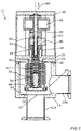
- FIG. 1 , 2 and 3 show a vacuum valve 10 with a housing 12.
- Housing 12 comprises a bottom member 14 defining a first chamber 16 having a first opening 18 and a second opening 20. Both openings 18, 20 are connected with flange sections 22a, 22b which allowed to integrate the vacuum valve 10 into a medium-, high- or ultra-high vacuum system.
- the upper side of chamber 16 is covered by wall element 24 which in turn abuts a wall portion 26 of a guidance device 28. Said wall portion 26 forms together with a cover element 30 a second chamber 32.
- multipartite housing 12 defines two chambers 16, 32 which - as it is described below - house a valve body (poppet 50) for sealing opening 18 and the key components needed for its actuation, respectively.
- Chamber 16 essentially functions as a passage between openings 18, 20.
- Second chamber 32 houses an electric motor 34 which is drivingly connected via a reduction drive 36 with a lead screw 38.
- Reduction drive 36 may comprise e.g. a spur gear, a worm gear and/or a planetary gear.
- Lead screw 38 cooperates with a nut 40 so that when electric motor 34 is active and causes a rotation of lead screw 38, nut 40 will move axially (movement AM in an axial direction) as a projection 42 of nut 40 engages in an axial slot 44 of guidance device 28 thereby preventing a rotation of nut 40.
- Nut 40 is fixedly connected to a sleeve 46.
- Sleeve 46 is provided with a first spring element 47 supported by an interior shoulder of sleeve 46 and acting on a tip element 48 which in turn contacts a poppet 50 provided with a seal 52.
- Seal 52 may e.g. be a conventional O-ring or a low force seal as described above and further below.
- a second spring element 54 is supported by an axial projection 56 of guidance device 28 projecting through an opening in wall element 24 into first chamber 16.
- Second spring element 54 acts on poppet 50 urging it downwardly towards opening 18. It surrounds a lower part of sleeve 46 in a radial direction and is in turn surrounded by a bellows 58 separating it from the interior of first chamber 16.
- electric motor 34 is activated driving lead screw 38.
- the rotation of lead screw 38 provokes an axial movement of nut 40 in a downward direction thereby also pushing sleeve 46 downwardly.
- This movement is transferred via first spring element 47 and tip element 48 on poppet 50 which is not fixedly connected to sleeve 46.
- This movement is supported by precompressed second spring element 54.
- the force provided by said spring element 54 acts in parallel to the thrust exerted on poppet 50 by the lead screw mechanism 38, 40 that converts a rotation of lead screw 38 into an axial translation of components 40, 46, 47, 48 and 50.
- second spring element 54 reduces the torque needed to create said axial translation and the energy consumption of electric motor 34 is reduced.
- electric motor 34 can be dimensioned relatively small, in particular if reduction drive 36 is chosen appropriately.
- seal 52 When seal 52 contacts a seat 60 surrounding opening 18, its compression sets in and the process of sealing opening 18 starts. At a given point the compression of seal 52 stagnates and poppet 50 stops moving in the axial direction. The poppet 50 is now in its closed position. As a clearance is provided between poppet 50 and sleeve 46, it is unproblematic if electric motor 34 still runs for a short time. This only causes a reduction of said clearance and a further compression of first spring element 47.
- an open-loop control of electric motor 34 e.g. a stepper motor
- small inaccuracies in the motor control can be compensated by that clearance.
- a position sensor may be provided that monitors the position of any of components 40, 46, 47 and 50 to be able to provide a closed-loop control of electric motor 34.
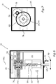
- Fig. 4 shows schematically a second embodiment of the vacuum valve 10.
- Electric motor 34 is arranged coaxially with reduction drive 36 which is in turn connected via a belt 62 and pulleys 64, 66 with lead screw 38.
- Lead screw 38 cooperates with nut 40 which is fixedly connected with a rod 68 carrying poppet 50 with seal 52.
- Axial guidance is provided in this embodiment by guide element 70 projecting through a guide opening 72 in nut 40.
- guide element 70 functions as a guide rail. Details regarding chamber 16 are omitted for clarity.
- a stroke S of the poppet is parallel to an axial movement AM of nut 40 during operation of valve 10.
- both stroke S and axial movement AM are movements in an axial direction.
- Fig. 5 shows in a top view that a rotational axis RA1 of pulley 64 (and of motor 34), a rotational axis RA2 of pulley 66 and lead screw 38 and an axial projection of rod 68 are disposed essentially on a diagonal D of cover 30. This arrangement is simple and compact.
- FIG. 6 and 7 An alternative compact arrangement is shown in Fig. 6 and 7 .
- Lead screw 38 is held by a bearing support 74 comprising bearings 76. It is driven by electric motor 34 connected to reduction drive 36 that in turn drives an output gear 78 meshing with an input gear 80 that is fixed to lead screw 38.
- Lead screw 38 cooperates with nut 40 that is axially movable but rotationally fixed.
- Nut 40 is connected by rod 68 to poppet 50.
- stroke S, axial movement AM and rotational axis RA2 of input gear 80 and lead screw 38 are coaxially arranged.
- Fig. 8 shows a flowchart to visualize exemplary approaches how to optimize a design of a vacuum valve according to the present invention and to adapt it to the requirements of the market.
- Important goals are, aside to energy efficiency, e.g. optimized flow conductance, optimized actuation motion and dynamics, compact size, low impact velocities during closure of the valve, temperature stability, reliable self-locking properties, reproducible duty-cycles.
- Non-performance related issues such as packaging, costs and manufacturability may also be considered during optimization of the valve.
- the leftmost flow requires as an input A1 the desired flow conductance through the valve.
- Suitable parameters as e.g. poppet or seal diameter and poppet stroke are chosen (A2) which leads to an actual flow conductance (A3).
- the parameters may be edited in order to change A3.
- the next flow to the right requires as an input of desired the seal material (B1).
- parameters regarding further properties of the seal e.g. its diameter, cross-section, elasticity, are chosen in step B2 as well as parameters describing how it is held (e.g. geometry of a groove in which the seal is disposed, that influences the response due to relative thermal expansion).
- This information leads to further insights as regards the actual squeeze force of the seal to expected and/or to be exerted (B3).
- the above-mentioned parameters may be edited. This allows to optimize the properties of the first spring element 47 (B4).
- the next flow to the right requires as an input e.g. the desired actuation profiles for linear motion and thrust of the poppet 50, the desired torque and rotational speed and the desired self-locking force (C1).
- Relevant parameters are e.g. the lead screw diameter and/or the characteristic friction between the lead screw and the nut (C2). This leads - inter alia - to the actual linear motion and the thrust response for drive torque and rotational speed of the components involved. Insights are further gained into the actual squeeze force and the actual self-locking force (C3). This allows to optimize the properties of the second spring element 54 (C4).
- the rightmost flow has as constraint the desired motor type (D1), such as brushed motor (D2), stepper motor (D3), in-runner (D4) or out-runner (D5).
- Relevant parameters are e.g. the motor torque, the provided rotational speed and the parameters regarding and/or defining duty-cycles (D6). This leads to the actually required or to be expected values of the actual "Power In” (D7).
- the selection of the suitable motor can be optimized on the basis of the relevant parameters.
- D8 it has to be decided if a reduction drive or an equivalent is needed or desirable.
- a relevant parameter here is the reduction ratio (D9) which leads to the actual torque and rotational speed provided to actuate the valve and the actual self-locking force that can be expected (D10).
- optimization flows described above are of exemplary nature only. Additional and/or modified optimization approaches may be adopted. The sequence in which the optimization flows are performed can be chosen freely.
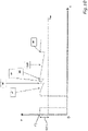
- Fig. 9 shows an exemplarily duty-cycle of the vacuum valve according to the present invention in a position (P) versus time (t) diagram.
- poppet 50 of the valve is in the fully open position (position P1).
- the velocity of the poppet 50 is actively reduced. This is reflected be the fact that the slope of the dashed movement curve is reduced before seal 52 contacts seat 60 (seal contact SC, position P2).
- the velocity of poppet 50 is further reduced until it reaches 0 in the closed position (position P3, time t1). Seal 52 has been compressed by the amount indicated with SR (squeeze range).
- the valve is suitably controlled so that metal-to-metal contact (MMC) between poppet 50 and seat 60 is avoided.
- MMC metal-to-metal contact
- one or more components of the electromechanical actuation unit have self-locking properties, e.g. the lead screw mechanism 38, 40 and/or the reduction drive 36, keeping the poppet 50 in the closed position does not require providing electric energy to motor 34.
- the opening of the vacuum valve starts at t2 (P4).
- the problems of generating vibrations and/or causing stress in the seal member 52 and/or the seat 60 and/or the valve body 50 are markedly less pronounced when opening the valve than during closure. Poppet 50 can therefore be accelerated rapidly. Decompression of seal 52 consequently occurs much more quickly than its compression.
- poppet 50 has already reached its maximum velocity when seal 52 loses contact with seat 60 of (position P5). It is further moved away from seat 60 until reaching the fully open position again (P6 at t3).
- the duty-cycle of the valve according to the present invention can be asymmetrical as regards opening and closing.
- closing the valve (0 to t1) takes longer than opening it (t2 to t3).
- This concept can be readily implemented by the electromechanical actuation unit of the vacuum valve according to the present invention, as such an actuation unit allows to control the position and the dynamics of the valve body/poppet very precisely. It is also possible to design for each application suitable position-time profiles and/or thrust profiles.
- Fig. 10 shows effects occurring during a closed state of the valve in a force (F) versus time (t) diagram.
- the horizontal dashed line shows a minimum thrust force (F min ) that should be exerted on seal 52 in order to ensure proper sealing.
- F min a minimum thrust force
- F1 squeezing force
- Differential thermal expansion of the components of the valve may lead to a reduction of the thrust or squeeze force (see ⁇ T).
- motor 34 can be activated to compensate said effect by a suitable response (see actuator response AR) in order to keep the force in a desired seal squeeze range SR1.
- Stress relaxation of the mechanical components involved can be another source a reduction of the force of exerted on seal 52 (see StR).
- a reduction in energy consumption of the vacuum valve can - independently from the nature of the actuation unit - also be achieved by using so-called "low force seals", i.e. seals that can be compressed suitably by the application of a relatively small force and/or that have sealing properties already at low forces.
- low force seals i.e. seals that can be compressed suitably by the application of a relatively small force and/or that have sealing properties already at low forces.
- Seals comprising a PTFE material or coating and/or comprising a fluoroelastomer material or coating are examples of such a low force seal.
- the required properties can also be obtained by departing from a circular cross-section of the seal and choosing non-circular geometries.
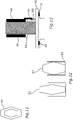
- a diamond-shaped seal 52 as depicted on the left side of Fig. 12 (disposed in groove 82, uncompressed) is deformed to a higher degree when a given force is applied ( Fig. 12 , right side) than a conventional O-ring of comparable dimensions. This effect is enhanced if seal 52 is at least partly hollow (see Fig. 11 ).
- Suitable hollow seals or seals with a softer core can also have geometries that differ from the diamond-shaped geometry shown in Fig. 11 .
- FIG. 13 An exemplary embodiment for mechanism to couple poppet 52 and sleeve 46 is shown in Fig. 13 .
- poppet 50 In an open state of the valve, poppet 50 is pressed away from sleeve 46 by spring-biased tip element 48 so that a clearance 84 between said components is provided. In this state, a projection of a finger 86 of sleeve 46 engages an upper end of a groove 88 of poppet 50 holding it in this position.
- the poppet 50 In a closed state of the valve, the poppet 50 has been moved towards sleeve 46 to compensate e.g. slight inaccuracies of the motor control and/or effects arising from progressive seal compression and/or thermal effects (situation shown in Fig. 13 ).
- sleeve 46 moves in an upward direction while poppet 50 is still pressed against seat 60 by spring elements 47, 54. Only when the projection of finger 86 engages the upper end of groove 86, poppet 50 is actively lifted from seat 60.
- Fig. 14 shows a further embodiment of a low force seal. It comprises seals 52a, 52b disposed on poppet 50 and seat 60, respectively, in an uncompressed situation. During closure of the valve, seals 52a, 52b are brought into contact with each other and are progressively compressed. As already set forth above, lower forces are needed to obtain an adequate sealing of such a valve than in conventionally arrangements.
- Fig. 15 to 18 show a compact vacuum valve 10 with an axially movable lead screw 38a cooperating with a nut 40a that is held axially fixed.
- Nut 40a is rotationally driven by electric motor 34a arranged between axial walls 90a, 90b.
- Valve 10 can be operated like the valve embodiments described above. It should be further noted that individual features described in connection with one embodiment can be implemented in the other embodiments, if needed. This holds true in particular for the functionality provided by spring elements 47, 54 described in connection with the embodiment shown in Figs. 1 and 2 .
Landscapes
- Engineering & Computer Science (AREA)
- General Engineering & Computer Science (AREA)
- Mechanical Engineering (AREA)
- Electrically Driven Valve-Operating Means (AREA)
- Details Of Valves (AREA)
Applications Claiming Priority (1)
| Application Number | Priority Date | Filing Date | Title |
|---|---|---|---|
| US17/690,470 US12104715B2 (en) | 2022-03-09 | 2022-03-09 | Vacuum valve |
Publications (4)
| Publication Number | Publication Date |
|---|---|
| EP4092298A2 true EP4092298A2 (de) | 2022-11-23 |
| EP4092298A3 EP4092298A3 (de) | 2023-02-15 |
| EP4092298B1 EP4092298B1 (de) | 2026-03-18 |
| EP4092298C0 EP4092298C0 (de) | 2026-03-18 |
Family
ID=81346121
Family Applications (1)
| Application Number | Title | Priority Date | Filing Date |
|---|---|---|---|
| EP22169276.7A Active EP4092298B1 (de) | 2022-03-09 | 2022-04-21 | Vakuumventil |
Country Status (5)
| Country | Link |
|---|---|
| US (2) | US12104715B2 (de) |
| EP (1) | EP4092298B1 (de) |
| JP (2) | JP2023133133A (de) |
| CN (1) | CN116733982A (de) |
| TW (1) | TWI848567B (de) |
Family Cites Families (29)
| Publication number | Priority date | Publication date | Assignee | Title |
|---|---|---|---|---|
| JPS4915291Y1 (de) | 1970-09-21 | 1974-04-17 | ||
| JPS5280517A (en) | 1975-12-26 | 1977-07-06 | Hitachi Ltd | Valve opening and closing mechanism for vacuum exhaust device |
| US5318272A (en) | 1992-06-12 | 1994-06-07 | Mks Instruments, Inc. | Motor controlled throttling poppet valve |
| JPH0650444A (ja) | 1992-07-31 | 1994-02-22 | Matsushita Electric Ind Co Ltd | 流量制御装置 |
| JPH06288493A (ja) | 1993-03-31 | 1994-10-11 | Shibaura Eng Works Co Ltd | 真空バルブ |
| JP3618286B2 (ja) * | 2000-09-07 | 2005-02-09 | Smc株式会社 | スムース排気弁 |
| JP2002089737A (ja) | 2000-09-18 | 2002-03-27 | Smc Corp | 真空排気弁 |
| JP2002286162A (ja) * | 2001-03-23 | 2002-10-03 | Megatorr Corp | 広帯域可変コンダクタンスバルブ |
| JP3668169B2 (ja) | 2001-09-17 | 2005-07-06 | 日本原子力発電株式会社 | 制御弁の作動診断装置 |
| JP2003194250A (ja) | 2001-12-27 | 2003-07-09 | Saginomiya Seisakusho Inc | 流量制御弁 |
| JP4171900B2 (ja) | 2003-05-19 | 2008-10-29 | Smc株式会社 | 真空調圧用バルブ |
| JP4055002B2 (ja) * | 2003-09-02 | 2008-03-05 | Smc株式会社 | 真空調圧用バルブ |
| WO2010026100A1 (de) * | 2008-09-05 | 2010-03-11 | Vat Holding Ag | Vakuumventil mit gasdichter wellendurchführung |
| WO2010084618A1 (ja) | 2009-01-26 | 2010-07-29 | 日本バルカー工業株式会社 | バルブ装置 |
| JP4914486B2 (ja) | 2009-12-25 | 2012-04-11 | シーケーディ株式会社 | 電動真空弁による排気速度制御方法、電動真空弁による排気速度制御システム、排気速度制御に用いられる電動真空弁の弁開度設定点決定方法、及び、排気速度制御に用いられる排気速度決定プログラム |
| KR101612495B1 (ko) | 2011-12-27 | 2016-04-14 | 다이호 고교 가부시키가이샤 | 밸브 장치 |
| JP5044725B1 (ja) * | 2012-04-27 | 2012-10-10 | 株式会社ブイテックス | シール材のつぶし量が制御可能なゲートバルブ |
| KR102270597B1 (ko) | 2014-04-02 | 2021-06-29 | 배트 홀딩 아게 | 진공밸브 |
| CN103968082A (zh) | 2014-05-22 | 2014-08-06 | 福建龙净环保股份有限公司 | 除尘器旁路阀 |
| JP6512426B2 (ja) | 2015-01-15 | 2019-05-15 | 株式会社Screenホールディングス | 基板処理装置 |
| JP2016138641A (ja) | 2015-01-29 | 2016-08-04 | アドバンス電気工業株式会社 | 流体制御弁の弁座部シール構造 |
| CN205026116U (zh) | 2015-07-28 | 2016-02-10 | 福建龙净环保股份有限公司 | 一种除尘器旁路阀装置 |
| WO2018079586A1 (ja) | 2016-10-26 | 2018-05-03 | 株式会社フジキン | 流量調整弁およびこれを用いた流体制御装置 |
| EP3392541A1 (de) * | 2017-04-19 | 2018-10-24 | VAT Holding AG | Vakuumventil mit kraftsensor |
| CN207975304U (zh) | 2018-02-27 | 2018-10-16 | 苏州欧纳克纳米科技有限公司 | 一种真空压力控制阀 |
| US10539250B2 (en) * | 2018-04-24 | 2020-01-21 | Honeywell International Inc. | High vibration, high cycle, pulse width modulated solenoid |
| JP2020051447A (ja) | 2018-09-25 | 2020-04-02 | 株式会社フジキン | バルブ |
| JP2021071129A (ja) | 2019-10-29 | 2021-05-06 | 株式会社フジキン | シートおよびバルブ |
| CN111022733A (zh) | 2019-12-12 | 2020-04-17 | 合肥宁泰真空设备有限公司 | 一种真空自动阀 |
-
2022
- 2022-03-09 US US17/690,470 patent/US12104715B2/en active Active
- 2022-04-21 EP EP22169276.7A patent/EP4092298B1/de active Active
-
2023
- 2023-01-26 JP JP2023010055A patent/JP2023133133A/ja active Pending
- 2023-02-16 TW TW112105616A patent/TWI848567B/zh active
- 2023-03-07 CN CN202310212008.3A patent/CN116733982A/zh active Pending
-
2024
- 2024-09-12 US US18/883,203 patent/US20250003525A1/en active Pending
- 2024-12-06 JP JP2024213041A patent/JP2025032235A/ja active Pending
Also Published As
| Publication number | Publication date |
|---|---|
| US20250003525A1 (en) | 2025-01-02 |
| CN116733982A (zh) | 2023-09-12 |
| US12104715B2 (en) | 2024-10-01 |
| EP4092298A3 (de) | 2023-02-15 |
| TW202400896A (zh) | 2024-01-01 |
| EP4092298B1 (de) | 2026-03-18 |
| EP4092298C0 (de) | 2026-03-18 |
| JP2025032235A (ja) | 2025-03-11 |
| TWI848567B (zh) | 2024-07-11 |
| JP2023133133A (ja) | 2023-09-22 |
| US20230287993A1 (en) | 2023-09-14 |
Similar Documents
| Publication | Publication Date | Title |
|---|---|---|
| AU2010318536B2 (en) | Electric actuators having internal load apparatus | |
| EP2499410B1 (de) | Kupplugsgerät für eine verwendung mit elektrischen aktuiatoren | |
| JP5397525B1 (ja) | 真空調圧システム | |
| US7533690B2 (en) | Multi-functional regulator | |
| EP2195567A1 (de) | Betätigungsventil | |
| US20080191155A1 (en) | Magnetically coupled valve actuator | |
| KR20120061905A (ko) | 게이트 밸브 | |
| KR101814423B1 (ko) | 유량 조정 밸브 | |
| WO2018109561A1 (en) | Balanced valve assembly | |
| EP4092298B1 (de) | Vakuumventil | |
| JP7808871B2 (ja) | 電動弁 | |
| WO2026085542A1 (en) | Expansion valve with anti-jamming system | |
| RU2260731C2 (ru) | Клапан осевого потока | |
| CN116658628A (zh) | 电动阀 |
Legal Events
| Date | Code | Title | Description |
|---|---|---|---|
| PUAI | Public reference made under article 153(3) epc to a published international application that has entered the european phase |
Free format text: ORIGINAL CODE: 0009012 |
|
| STAA | Information on the status of an ep patent application or granted ep patent |
Free format text: STATUS: THE APPLICATION HAS BEEN PUBLISHED |
|
| AK | Designated contracting states |
Kind code of ref document: A2 Designated state(s): AL AT BE BG CH CY CZ DE DK EE ES FI FR GB GR HR HU IE IS IT LI LT LU LV MC MK MT NL NO PL PT RO RS SE SI SK SM TR |
|
| PUAL | Search report despatched |
Free format text: ORIGINAL CODE: 0009013 |
|
| AK | Designated contracting states |
Kind code of ref document: A3 Designated state(s): AL AT BE BG CH CY CZ DE DK EE ES FI FR GB GR HR HU IE IS IT LI LT LU LV MC MK MT NL NO PL PT RO RS SE SI SK SM TR |
|
| RIC1 | Information provided on ipc code assigned before grant |
Ipc: F16J 15/02 19680901ALI20230112BHEP Ipc: F16K 51/02 19740701ALI20230112BHEP Ipc: F16K 41/10 19680901ALI20230112BHEP Ipc: F16K 31/04 19680901ALI20230112BHEP Ipc: F16K 1/36 19680901ALI20230112BHEP Ipc: F16K 31/50 19680901AFI20230112BHEP |
|
| STAA | Information on the status of an ep patent application or granted ep patent |
Free format text: STATUS: REQUEST FOR EXAMINATION WAS MADE |
|
| 17P | Request for examination filed |
Effective date: 20230330 |
|
| RBV | Designated contracting states (corrected) |
Designated state(s): AL AT BE BG CH CY CZ DE DK EE ES FI FR GB GR HR HU IE IS IT LI LT LU LV MC MK MT NL NO PL PT RO RS SE SI SK SM TR |
|
| STAA | Information on the status of an ep patent application or granted ep patent |
Free format text: STATUS: EXAMINATION IS IN PROGRESS |
|
| 17Q | First examination report despatched |
Effective date: 20231005 |
|
| GRAP | Despatch of communication of intention to grant a patent |
Free format text: ORIGINAL CODE: EPIDOSNIGR1 |
|
| STAA | Information on the status of an ep patent application or granted ep patent |
Free format text: STATUS: GRANT OF PATENT IS INTENDED |
|
| INTG | Intention to grant announced |
Effective date: 20251117 |
|
| GRAS | Grant fee paid |
Free format text: ORIGINAL CODE: EPIDOSNIGR3 |
|
| GRAA | (expected) grant |
Free format text: ORIGINAL CODE: 0009210 |
|
| STAA | Information on the status of an ep patent application or granted ep patent |
Free format text: STATUS: THE PATENT HAS BEEN GRANTED |
|
| AK | Designated contracting states |
Kind code of ref document: B1 Designated state(s): AL AT BE BG CH CY CZ DE DK EE ES FI FR GB GR HR HU IE IS IT LI LT LU LV MC MK MT NL NO PL PT RO RS SE SI SK SM TR |
|
| REG | Reference to a national code |
Ref country code: CH Ref legal event code: F10 Free format text: ST27 STATUS EVENT CODE: U-0-0-F10-F00 (AS PROVIDED BY THE NATIONAL OFFICE) Effective date: 20260318 Ref country code: GB Ref legal event code: FG4D |
|
| REG | Reference to a national code |
Ref country code: CH Ref legal event code: R17 Free format text: ST27 STATUS EVENT CODE: U-0-0-R10-R17 (AS PROVIDED BY THE NATIONAL OFFICE) Effective date: 20260323 |
|
| REG | Reference to a national code |
Ref country code: IE Ref legal event code: FG4D |
|
| U01 | Request for unitary effect filed |
Effective date: 20260318 |
|
| U07 | Unitary effect registered |
Designated state(s): AT BE BG DE DK EE FI FR IT LT LU LV MT NL PT RO SE SI Effective date: 20260324 |