EP4091697B1 - Set zur reinigung eines luftstroms - Google Patents
Set zur reinigung eines luftstroms Download PDFInfo
- Publication number
- EP4091697B1 EP4091697B1 EP22185230.4A EP22185230A EP4091697B1 EP 4091697 B1 EP4091697 B1 EP 4091697B1 EP 22185230 A EP22185230 A EP 22185230A EP 4091697 B1 EP4091697 B1 EP 4091697B1
- Authority
- EP
- European Patent Office
- Prior art keywords
- hollow body
- set according
- cleaning
- airflow
- separating structure
- Prior art date
- Legal status (The legal status is an assumption and is not a legal conclusion. Google has not performed a legal analysis and makes no representation as to the accuracy of the status listed.)
- Active
Links
Images


Classifications
-
- B—PERFORMING OPERATIONS; TRANSPORTING
- B01—PHYSICAL OR CHEMICAL PROCESSES OR APPARATUS IN GENERAL
- B01D—SEPARATION
- B01D45/00—Separating dispersed particles from gases or vapours by gravity, inertia, or centrifugal forces
- B01D45/04—Separating dispersed particles from gases or vapours by gravity, inertia, or centrifugal forces by utilising inertia
- B01D45/08—Separating dispersed particles from gases or vapours by gravity, inertia, or centrifugal forces by utilising inertia by impingement against baffle separators
-
- B—PERFORMING OPERATIONS; TRANSPORTING
- B01—PHYSICAL OR CHEMICAL PROCESSES OR APPARATUS IN GENERAL
- B01D—SEPARATION
- B01D46/00—Filters or filtering processes specially modified for separating dispersed particles from gases or vapours
- B01D46/40—Particle separators, e.g. dust precipitators, using edge filters, i.e. using contiguous impervious surfaces
- B01D46/406—Particle separators, e.g. dust precipitators, using edge filters, i.e. using contiguous impervious surfaces of stacked bodies
-
- B—PERFORMING OPERATIONS; TRANSPORTING
- B01—PHYSICAL OR CHEMICAL PROCESSES OR APPARATUS IN GENERAL
- B01D—SEPARATION
- B01D50/00—Combinations of methods or devices for separating particles from gases or vapours
- B01D50/20—Combinations of devices covered by groups B01D45/00 and B01D46/00
-
- B—PERFORMING OPERATIONS; TRANSPORTING
- B05—SPRAYING OR ATOMISING IN GENERAL; APPLYING FLUENT MATERIALS TO SURFACES, IN GENERAL
- B05B—SPRAYING APPARATUS; ATOMISING APPARATUS; NOZZLES
- B05B14/00—Arrangements for collecting, re-using or eliminating excess spraying material
- B05B14/40—Arrangements for collecting, re-using or eliminating excess spraying material for use in spray booths
-
- B—PERFORMING OPERATIONS; TRANSPORTING
- B01—PHYSICAL OR CHEMICAL PROCESSES OR APPARATUS IN GENERAL
- B01D—SEPARATION
- B01D39/00—Filtering material for liquid or gaseous fluids
- B01D39/14—Other self-supporting filtering material ; Other filtering material
- B01D39/16—Other self-supporting filtering material ; Other filtering material of organic material, e.g. synthetic fibres
- B01D39/18—Other self-supporting filtering material ; Other filtering material of organic material, e.g. synthetic fibres the material being cellulose or derivatives thereof
-
- B—PERFORMING OPERATIONS; TRANSPORTING
- B01—PHYSICAL OR CHEMICAL PROCESSES OR APPARATUS IN GENERAL
- B01D—SEPARATION
- B01D46/00—Filters or filtering processes specially modified for separating dispersed particles from gases or vapours
- B01D46/0002—Casings; Housings; Frame constructions
-
- B—PERFORMING OPERATIONS; TRANSPORTING
- B01—PHYSICAL OR CHEMICAL PROCESSES OR APPARATUS IN GENERAL
- B01D—SEPARATION
- B01D46/00—Filters or filtering processes specially modified for separating dispersed particles from gases or vapours
- B01D46/0002—Casings; Housings; Frame constructions
- B01D46/0016—Folded frame or housing constructions
-
- Y—GENERAL TAGGING OF NEW TECHNOLOGICAL DEVELOPMENTS; GENERAL TAGGING OF CROSS-SECTIONAL TECHNOLOGIES SPANNING OVER SEVERAL SECTIONS OF THE IPC; TECHNICAL SUBJECTS COVERED BY FORMER USPC CROSS-REFERENCE ART COLLECTIONS [XRACs] AND DIGESTS
- Y10—TECHNICAL SUBJECTS COVERED BY FORMER USPC
- Y10S—TECHNICAL SUBJECTS COVERED BY FORMER USPC CROSS-REFERENCE ART COLLECTIONS [XRACs] AND DIGESTS
- Y10S55/00—Gas separation
- Y10S55/31—Filter frame
Definitions
- the present invention relates to a set for cleaning an air stream.
- the modular arrangement of filter modules made of cardboard is from the WO 03/084638 A2 They are used to separate paint particles or paint mist (overspray) from the exhaust air of a spray booth in which, for example, parts for a vehicle are painted.
- the exhaust air from spray booths contains a wide variety of paint contamination, which differ, for example, in terms of particle size and moisture content.
- paint contamination differ, for example, in terms of particle size and moisture content.
- labyrinths with small openings and strong deflections must be provided for separation, so that the particles are stopped by their inertia (or centrifugal force) on the baffle walls of the labyrinth or separator, while the cleaned air exits behind the filter module.
- the object of the invention is to provide a set consisting of a hollow body and To create cleaning substructures which allow a broader range of applications, ie are suitable for the separation of paint particles and paint mist with a greater variety than is the case in the prior art.
- the set having a hollow body which has an inlet opening for the entry of an air flow to be cleaned and an outlet opening for the exit of the cleaned air flow, as well as several cleaning substructures as separation structures for cleaning the air flow by separating particles and/or for filtering the air flow.
- cleaning substructures and/or the cleaning modules are independently interchangeable.
- the at least two cleaning substructures comprise a filter structure.
- Such filter structures can be designed in various ways.
- a mat or a fleece made of glass fibers can be used here. Preferred thicknesses of such mats or fleeces are preferably less than 20 cm and particularly preferably less than 10 cm.
- so-called Columbus material can be used as filter material. This consists of paper, preferably waste paper, in which parallel and offset slots are punched or cut. Openings are created by pulling across the slots. Several layers of this material can advantageously be used as Filter material can be used.
- Separation structures can also be designed in different ways. For example, after unfolding, they can be rectangular structures in a top view. But diamond-shaped structures are also known (for example, sold under the name "Andreae").
- Cleaning modules can be arranged in slide-in frames. These slide-in frames can extend over a wall, the ceiling or the floor of the spray booth. In these slide-in frames, the cleaning modules can be arranged one behind the other and removed or replaced individually.
- the at least two cleaning substructures can have at least one separation structure for cleaning an air flow, wherein the at least one separation structure preferably comprises at least two baffles which follow one another in the direction of the air flow and are provided with openings.
- the separation structure can be given increased stability by providing at least one stabilizing wall.
- the at least one stabilizing wall is connected to the at least two impact walls.
- the at least one stabilizing wall is connected to the at least two impact walls in a foldable and/or articulated manner.
- the at least one stabilizing wall is aligned substantially parallel to the air flow.
- separation structures can be provided in different geometric dimensions, in particular thicknesses.
- Separation structures can also be provided which are optimized for the separation of particles of different sizes, in particular through the size of the openings.
- the separation structures can be designed in such a way that those with larger geometric dimensions, in particular thicknesses, are optimized for the separation of larger particles and vice versa.
- Another advantage is that the selective interchangeability of the cleaning modules means that less storage is required.
- the cleaning substructures when viewed along an axis which is essentially parallel to the air flow when arranged in the hollow body, have an outline which essentially corresponds to a cross section of a hollow space in the hollow body, preferably perpendicular to the air flow. This also ensures that no part of the air flow remains uncleaned because there is no path past the cleaning substructures.
- At least one separation structure is foldable.
- the reduced volume makes storage and transport of the separation structures considerably easier.
- the reinforcing effect of a stabilizing wall can be improved by inhibiting the folding of the separation structure when arranged in the hollow body by inner walls of the hollow body.
- the at least one stabilizing wall is arranged substantially centrally with respect to a direction in the plane of the impact walls. This can optimize the reinforcing effect of the stabilizing wall.
- the at least one stabilizing wall can be connected to the at least two impact walls, preferably in a foldable and/or articulated manner. This can be easily achieved using a film hinge, for example. This enables a very flat structure in the folded state, which has a high degree of rigidity in the unfolded state.
- the at least one stabilizing wall is aligned substantially parallel to the air flow. This is because, in particular when the cleaning module is arranged in a floor or ceiling of a spray booth, the direction of the air flow corresponds to the direction of the main load on the separation structure.
- the hollow body and/or at least one separation structure is made of cardboard, paper or paperboard. This makes it particularly easy to remove or recycle the separation structures or the cleaning modules. However, it is also entirely conceivable to manufacture separation structures and/or hollow bodies from metal, plastic, wood or the like.
- At least one separation structure has at least two tabs aligned substantially parallel to the air flow, between which a further Separation structure can be arranged.
- a separation structure can serve different intended geometric dimensions, in particular thicknesses. This means that it can be used either with a separation structure arranged between the tabs, or without. In the latter case, the tabs serve as spacers to an inner wall of the hollow body or another separation structure.
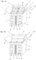
- the cleaning module 10 shown comprises a hollow body 5 and an inlet opening 6 for the entry of the air flow to be cleaned. Since the outlet opening is arranged on the back of the hollow body 5, it cannot be seen in these representations. The outlet opening is designed essentially analogously to the inlet opening 6.
- the hollow body 5 has opening elements 8 designed as opening tabs. These are opened in the present illustration so that the view of the interior of the hollow body 5 is clear.
- opening elements 8 designed as opening tabs. These are opened in the present illustration so that the view of the interior of the hollow body 5 is clear.
- FIG 1a Several cleaning substructures 7 are shown, which in this case are all designed as separation structures 1.
- the separation structures 1 have baffles 2, which are provided with openings 3.
- baffles 2 and all openings 3 are provided with reference symbols, since these are sometimes present in large numbers.
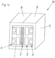
- FIG 1b is analogous to Figure 1a only with the difference that two of the cleaning substructures 7 are designed as filter structures 9.
- These filter structures 9 comprise glass fiber mats or fleeces, but can also comprise Columbus material or the like.
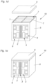
- the opening elements 8 can also be designed as a removable lid (shoebox-like), which is Figures 1d and 1e Otherwise, the cleaning module 10 is made of the Figures 1d and 1e analogous to those from the Figures 1a to 1c .
- FIG. 2a to 2h a first embodiment of a deposition structure 1 is shown in different folding states for a better understanding of the invention.
- Figure 2a shows the separation structure 1 in the delivery state. Parts of the structure are then unfolded ( Figure 2b ). The entire separation structure 1 is then folded together again, whereby the Figure 2b unfolded parts face each other.
- the separation structure 1 is designed in such a way that it can be used in a cleaning module 10 ( Figure 2e).
- Figure 2f corresponds Figure 2e , whereby the separation structure 1 is shown rotated, which is illustrated by arrows.
- the separation structure 1 can be folded by a single folding operation ( Figure 2g ) essentially be made flat ( Figure 2h ). This can simplify disposal.
- FIGS 3a to 3c show a further deposition structure 1 according to the invention.
- This can be seen from the delivery state ( Figure 3a ) by a folding operation ( Figure 3b ), which is indicated with arrows, can be put into the operating state ( Figure 3c ).
- the arrangement of the stabilizing walls 4 between the impact walls 2 is particularly clearly visible.
- the stabilizing walls 4 are arranged essentially centrally with respect to a direction in the plane of the impact walls 2.
- Tabs 11 can also be seen, between which on the one hand further separation structures 1 can be arranged - in order to save space - and which on the other hand can act as spacers so that the separation structure 1 sits firmly in the cleaning module 10.
- FIGS 4a and 4b schematically show cleaning substructures 7 of different geometric dimensions, in particular thickness, as well as different combinations of their arrangement in a cleaning module 10.
- the cleaning substructures 7 are provided in three different thicknesses of 100 mm, 200 mm, 300 mm or 500 mm, with the thicknesses being noted on the cleaning substructures 7.
- the different total thicknesses 100 mm, 200 mm, 300 mm or 500 mm are noted on the cleaning modules 10.
- Versions 1 to 6 each have a cleaning module 10, which can accommodate cleaning substructures 7 with a total thickness of 500 mm.
- the cleaning module 10 accommodates cleaning substructures with a total thickness of 300 mm.
- Versions 10 and 11 refer to cleaning modules 10 with a total thickness of 200 mm.
- Version 12 refers to a cleaning module with a total thickness of 100 mm.
- Version 13 refers to a cleaning module with a total thickness of 500 mm. The various possible combinations are shown there.
- the cleaning substructure 7, which is 300 mm thick, has tabs 11. For the sake of clarity, not all tabs 11 are provided with reference symbols. This means that this cleaning substructure 7, designed as a separating structure 1, can be used as a cleaning substructure 7 with a thickness of 300 mm (embodiments 6 and 7 in Figure 4b ) or with a thickness of 200 mm (design 1 from Figure 4b ) serve.
- Cleaning modules 10 can be arranged one behind the other in slide-in frames 12. Here too, various combinations are possible, which can be seen schematically (left) and in perspective (right) in the Figures 5a to 5e is shown. Preferably, cleaning modules 10 which are optimized for coarser paint contamination or paint droplets are arranged facing the contaminated air flow. These can then be changed individually. Those cleaning modules 10 which reach their capacity limit later can remain in the slide-in frame 12 for longer.
Landscapes
- Chemical & Material Sciences (AREA)
- Chemical Kinetics & Catalysis (AREA)
- Filtering Of Dispersed Particles In Gases (AREA)
- Separating Particles In Gases By Inertia (AREA)
- Separation Using Semi-Permeable Membranes (AREA)
- Cleaning In General (AREA)
- Cable Accessories (AREA)
- Flanged Joints, Insulating Joints, And Other Joints (AREA)
- Pipe Accessories (AREA)
- Details Or Accessories Of Spraying Plant Or Apparatus (AREA)
- Filtering Materials (AREA)
Description
- Die vorliegende Erfindung betrifft ein Set zur Reinigung eines Luftstroms.
- Die modulare Anordnung von Filtermodulen aus Karton ist aus der
WO 03/084638 A2 - Bemerkenswert ist hierbei, dass eine sehr große Vielzahl an verschiedenen Lacken verwendet wird. Dadurch sind in der Abluft von Sprühkabinen verschiedenste Arten von Lackverunreinigungen vorhanden, welche sich beispielsweise durch Partikelgröße und Feuchtigkeitsanteil unterscheiden. Für relativ kleine, trockene Partikel müssen zur Abscheidung Labyrinthe mit kleinen Öffnungen und starken Umlenkungen bereit gestellt werden, sodass die Partikel durch Ihre Trägheit (bzw. durch die Fliehkraft) an Prallwänden des Labyrinths bzw. des Abscheiders gestoppt werden, während die gereinigte Luft hinter dem Filtermodul austritt.
- Bei großen Partikelgrößen mit hohem Feuchtigkeitsanteil kann über kurze Zeit eine große Menge von Lack in einem Reinigungsmodul abgeschieden werden. Insbesondere dann, wenn die Reinigungsmodule im Boden der Sprühkabine angeordnet sind, resultiert dies in einer großen Belastung des aus Karton gefertigten Reinigungsmoduls, welche durch die Sogwirkung eines Gebläses zur Erzeugung des Luftstroms durch die Reinigungsmodule noch vergrößert wird. Dies führt bei Reinigungsmodulen nach dem Stand der Technik dazu, dass die darin vorhandenen Abscheidestrukturen unter ihrem mit Lack beladenen Eigengewicht zusammenfallen und ihre Funktion nicht mehr erfüllen.
- Aufgabe der Erfindung ist es, ein Set aus einem Hohlkörper und Reinigungsteilstrukturen zu schaffen, welche einen verbreiterten Anwendungsbereich erlauben, d. h. zur Abscheidung von Lackpartikeln und Lacknebel mit größerer Vielfalt geeignet sind, als dies im Stand der Technik der Fall ist.
- Diese Aufgabe wird durch ein Set mit den Merkmalen des Anspruchs 1 gelöst.
- Erfindungsgemäß geschieht dies, indem das Set einen Hohlkörper aufweist, welcher eine Eintrittsöffnung für den Eintritt eines zu reinigenden Luftstroms und eine Austrittsöffnung für den Austritt des gereinigten Luftstroms aufweist, sowie mehreren Reinigungsteilstrukturen als Abscheidestrukturen zur Reinigung des Luftstroms durch Abscheidung von Partikeln und/oder zur Filtration des Luftstroms. Durch die Bereitstellung eines Sets, in welchem zumindest zwei verschiedene Kombinationen von Reinigungsteilstrukturen im Hohlkörper anordenbar sind, kann eine noch breitere Anwendbarkeit erzielt werden.
- Insbesondere kann es vorgesehen sein, dass Reinigungsteilstrukturen und/oder die Reinigungsmodule unabhängig voneinander austauschbar sind.
- Weitere vorteilhafte Ausführungsformen sind in den abhängigen Ansprüchen definiert.
- Um auch sehr feine Lacknebel aus dem Luftstrom entfernen zu können, kann es vorgesehen sein, dass die wenigstens zwei Reinigungsteilstrukturen eine Filterstruktur umfassen. Derartige Filterstrukturen können verschiedenartig ausgebildet sein. Beispielsweise kann hier eine Matte oder ein Flies aus Glasfasern zum Einsatz kommen. Bevorzugte Dicken solcher Matten oder Vliese liegen bevorzugt unter 20 cm und besonders bevorzugt unter 10 cm. Außerdem kann als Filtermaterial sogenanntes Columbusmaterial verwendet werden. Dieses besteht aus Papier, vorzugsweise Altpapier, in welches parallele und versetzte Schlitze gestanzt oder geschnitten sind. Durch Zug quer zu den Schlitzen entstehen Öffnungen. Mehrere Lagen dieses Materials können vorteilhaft als Filtermaterial verwendet werden.
- Abscheidestrukturen können ebenfalls auf verschiedene Arten ausgestaltet sein. Beispielsweise können diese nach dem Auffalten in einer Draufsicht rechteckige Strukturen sein. Aber auch rautenförmige Strukturen sind bekannt (beispielsweise vertrieben unter der Bezeichnung "Andreae").
- Reinigungsmodule können in Einschubrahmen angeordnet werden. Diese Einschubrahmen können sich über eine Wand, die Decke oder den Boden der Sprühkabine erstrecken. In diesen Einschubrahmen können die Reinigungsmodule hintereinander angeordnet und einzeln herausgenommen bzw. ersetzt werden.
- Die zumindest zwei Reinigungsteilstrukturen können zumindest eine Abscheidestruktur zur Reinigung eines Luftstroms aufweisen, wobei die wenigstens eine Abscheidestruktur vorzugsweise wenigstens zwei, in Richtung des Luftstroms aufeinanderfolgende Prallwände, welche mit Öffnungen versehen sind, umfasst.
- Der Abscheidestruktur kann durch das Vorsehen zumindest einer Stabilisierungswand eine erhöhte Stabilität verliehen werden.
- Es kann vorgesehen sein, dass die wenigstens eine Stabilisierungswand mit den wenigstens zwei Prallwänden in Verbindung steht.
- Es kann außerdem vorgesehen sein, dass die wenigstens eine Stabilisierungswand mit den wenigstens zwei Prallwänden faltbar und/oder gelenkig in Verbindung steht.
- Des Weiteren kann vorgesehen sein, dass die wenigstens eine Stabilisierungswand im Wesentlichen parallel zum Luftstrom ausgerichtet ist.
- Bevorzugt vorgesehen können Abscheidestrukturen in verschiedenen geometrischen Abmessungen, insbesondere Stärken, vorgesehen sein.
- Ebenso können Abscheidestrukturen vorgesehen sein, welche, insbesondere durch die Größe der Öffnungen, auf die Abscheidung von Partikeln unterschiedlicher Größe optimiert sind. Insbesondere können die Abscheidestrukturen so gestaltet sein, dass diejenigen mit größeren geometrischen Abmessungen, insbesondere Stärken, auf die Abscheidung größerer Partikel optimiert sind und umgekehrt.
- Dies ermöglicht eine genaue Anpassung des Reinigungsmoduls an die vorliegende Verschmutzung im Luftstrom (Partikelgröße, Feuchtigkeitsgrad). Dies ermöglicht außerdem ein selektives Tauschen von hintereinander angeordneten Reinigungsmodulen, was von Vorteil ist, da auf verschiedene Partikelgrößen optimierte Abscheidestrukturen unterschiedlich schnell ihre Kapazitätsgrenze erreichen.
- Weiterhin von Vorteil ist, dass die durch die selektive Tauschbarkeit der Reinigungsmodule Lagerhaltung im geringeren Umfang notwendig ist.
- Für einen guten Sitz der Reinigungsteilstrukturen im Hohlkörper kann es vorgesehen sein, dass die Reinigungsteilstrukturen in einer Ansicht entlang einer Achse, welche beim im Hohlkörper angeordneten Zustand, im Wesentlichen parallel zum Luftstrom ist, einen Umriss aufweisen, welcher einem, vorzugsweise zum Luftstrom senkrechten, Querschnitt eines Hohlraums des Hohlkörpers im Wesentlichen entspricht. Dies stellt außerdem sicher, dass kein Teilstrom des Luftstroms ungereinigt bleibt, weil kein Weg an den Reinigungsteilstrukturen vorbeiführt.
- Besonders bevorzugt kann es vorgesehen sein, dass zumindest eine Abscheidestruktur zusammenfaltbar ist. Durch das verringerte Volumen wird die Lagerung und der Transport der Abscheidestrukturen erheblich erleichtert.
- Dieser Effekt verstärkt sich noch, falls vorgesehen ist, dass die zumindest eine Abscheidestruktur nach dem Zusammenfalten im Wesentlichen flach ist.
- Die verstärkende Wirkung einer Stabilisierungswand kann verbessert werden, indem das Zusammenfalten der Abscheidestruktur beim im Hohlkörper angeordneten Zustand durch Innenwandungen des Hohlkörpers gehemmt ist.
- Bevorzugt kann es vorgesehen sein, dass die wenigstens eine Stabilisierungswand im Wesentlichen mittig bezüglich einer Richtung in der Ebene der Prallwände angeordnet ist. Dies kann die Verstärkungswirkung der Stabilisierungswand optimieren.
- Die wenigstens eine Stabilisierungswand kann mit den wenigstens zwei Prallwänden verbunden sein, wobei dies vorzugsweise auf faltbare und/oder gelenkige Art und Weise der Fall ist. Einfach realisierbar ist dies beispielsweise über ein Filmscharnier. Dies ermöglicht eine sehr flache Struktur im zusammengefalteten Zustand, welche im entfalteten Zustand eine hohe Steifigkeit aufweist.
- Weiterhin kann es bevorzugt vorgesehen sein, dass die wenigstens eine Stabilisierungswand im Wesentlichen parallel zum Luftstrom ausgerichtet ist. Denn insbesondere dann, wenn das Reinigungsmodul in einem Boden oder einer Decke einer Sprühkabine angeordnet ist, entspricht die Richtung des Luftstroms derjenigen Richtung der Hauptbelastung der Abscheidestruktur.
- Ganz besonders bevorzugt kann es vorgesehen sein, dass der Hohlkörper und/oder zumindest eine Abscheidestruktur aus Karton, Papier oder Pappe besteht. Ein besonders einfaches Beseitigen bzw. Recyclen der Abscheidestrukturen bzw. der Reinigungsmodule wird hierdurch ermöglicht. Es ist aber durchaus auch denkbar Abscheidestrukturen und/oder Hohlkörper aus Metall, Kunststoff, Holz oder dergleichen zu fertigen.
- In einer weiteren bevorzugten Ausführung kann vorgesehen sein, dass zumindest eine Abscheidestruktur wenigstens zwei im Wesentlichen parallel zum Luftstrom ausgerichtete Laschen aufweist, zwischen denen im Hohlkörper eine weitere Abscheidestruktur anordenbar ist. Dadurch ist es möglich, dass eine Abscheidestruktur für verschiedene vorgesehene geometrische Abmessungen, insbesondere Stärken, dient. Das bedeutet, sie kann entweder mit einer zwischen den Laschen angeordneten Abscheidestruktur eingesetzt werden, oder ohne. In letzterem Fall dienen die Laschen als Abstandhalter zu einer Innenwandung des Hohlkörpers oder einer weiteren Abscheidestruktur.
- Weitere Vorteile und Einzelheiten der Erfindung sind anhand der Figuren, sowie der dazugehörigen Figurenbeschreibung ersichtlich. Dabei zeigen:
-
Fig. 1a bis 1h : verschiedene perspektivische, schematische Darstellungen Reinigungsmodule zum besseren Verständnis der Erfindung, -
Fig. 2a bis 2h : perspektivische Darstellungen einer Abscheidestruktur in verschiedenen Faltzuständen zum besseren Verständnis der Erfindung, -
Fig. 3a bis 3c : eine weitere Ausführungsform einer erfindungsgemäßen Abscheidestruktur in verschiedenen Faltzuständen -
Fig. 4a und 4b : schematische Darstellungen verschiedener Kombinationsmöglichkeiten von Abscheidestrukturen in Reinigungsmodulen zum besseren Verständnis der Erfindung, sowie -
Fig. 5a bis 5e : Darstellungen von Anordnungsmöglichkeiten von Reinigungsmodulen in Einschubrahmen zum besseren Verständnis der Erfindung. - Das in
Figur 1a dargestellte Reinigungsmodul 10 umfasst zunächst einen Hohlkörper 5, sowie eine Eintrittsöffnung 6 zum Eintritt des zu reinigenden Luftstroms. Da die Austrittsöffnung auf der Rückseite des Hohlkörpers 5 angeordnet ist, kann sie in diesen Darstellungen nicht erkannt werden. Die Austrittsöffnung ist im Wesentlichen analog zur Eintrittsöffnung 6 ausgebildet. - Der Hohlkörper 5 verfügt über - als Öffnungslaschen ausgebildete - Öffnungselemente 8. Diese sind in der vorliegenden Darstellung geöffnet, sodass der Blick aufs Innenleben des Hohlkörpers 5 frei wird. In
Figur 1a sind mehrere Reinigungsteilstrukturen 7 dargestellt, welche in diesem Fall allesamt als Abscheidestrukturen 1 ausgebildet sind. Die Abscheidestrukturen 1 verfügen über Prallwände 2, welche mit Öffnungen 3 versehen sind. Der Übersichtlichkeit halber sind nicht alle Prallwände 2 und alle Öffnungen 3 mit Bezugszeichen versehen, da diese teilweise in einer Vielzahl vorliegen. -
Figur 1b ist analog zuFigur 1a nur mit dem Unterschied, dass zwei der Reinigungsteilstrukturen 7 als Filterstrukturen 9 ausgebildet sind. Diese Filterstrukturen 9 umfassen Glasfasermatten oder Vliese, können aber auch Columbusmaterial oder ähnliches umfassen. - In
Figur 1c ist erneut das Reinigungsmodul 10 dargestellt, dieses Mal jedoch mit geschlossenen Öffnungselementen 8. In diesem Zustand kann das Reinigungsmodul eingesetzt werden. - Die Öffnungselemente 8 können auch als abnehmbarer Deckel ausgeführt sein (schuhkartonartig), was in den
Figuren 1d und 1e dargestellt ist. Ansonsten ist das Reinigungsmodul 10 aus denFiguren 1d und 1e analog zu denen aus denFiguren 1a bis 1c . - In den
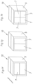
Figuren 1f bis 1h sind weitere Ausführungsformen dargestellt, wobei sich die Reinigungsteilstrukturen 7 in diesen Fällen nicht über die gesamte Querschnittsfläche (aus sicht des Luftstroms, welcher nebenFigur 1f durch einen Pfeil angedeutet ist) des Hohlkörpers 5 erstrecken. - In den
Figuren 2a bis 2h ist eine erste Ausführungsform einer Abscheidestruktur 1 in verschiedenen Faltzuständen zum besseren Verständnis der Erfindung dargestellt.Figur 2a zeigt dabei zunächst die Abscheidestruktur 1 im Auslieferungszustand. Teile der Struktur werden dann aufgefaltet (Figur 2b ). Die gesamte Abscheidestruktur 1 wird danach noch einmal zusammengefaltet, wobei die inFigur 2b aufgefalteten Teile zueinander weisen. - Dann liegt die Abscheidestruktur 1 so vor, dass sie bei einem Reinigungsmodul 10 eingesetzt werden kann (
Figur 2e). Figur 2f entsprichtFigur 2e , wobei die Abscheidestruktur 1 gedreht dargestellt ist, was durch Pfeile verdeutlicht ist. Nach dem Gebrauch in einem Reinigungsmodul 10, beispielsweise beim Entsorgen des Reinigungsmoduls 10, kann die Abscheidestruktur 1 durch eine einzige Faltoperation (Figur 2g ) im Wesentlichen flach gemacht werden (Figur 2h ). Dies kann die Entsorgung vereinfachen. - Die
Figuren 3a bis 3c zeigen eine weitere erfindungsgemäße Abscheidestruktur 1. Diese kann aus dem Auslieferungszustand (Figur 3a ) durch eine Faltoperation (Figur 3b ), welche mit Pfeilen angedeutet ist, in den Betriebszustand versetzt werden (Figur 3c ). An diesem Ausführungsbeispiel ist besonders deutlich die Anordnung der Stabilisierungswände 4 zwischen den Prallwänden 2 ersichtlich. Die Stabilisierungswände 4 sind im Wesentlichen mittig bezüglich einer Richtung in der Ebene der Prallwände 2 angeordnet. Zu erkennen sind ebenfalls Laschen 11, zwischen welchen einerseits weitere Abscheidestrukturen 1 angeordnet werden können - um Platz zu sparen - und welche andererseits als Abstandshalter fungieren können, sodass die Abscheidestruktur 1 fest im Reinigungsmodul 10 sitzt. - In den
Figuren 4a und 4b sind schematisch Reinigungsteilstrukturen 7 verschiedener geometrischer Dimensionen, insbesondere Stärke, sowie verschiedene Kombinationen ihrer Anordnung in einem Reinigungsmodul 10 dargestellt. Die Reinigungsteilstrukturen 7 sind in dieser Ausführung in drei verschiedenen Stärken von 100 mm, 200 mm, 300 mm oder 500 mm vorgesehen, wobei die Stärken jeweils auf den Reinigungsteilstrukturen 7 vermerkt sind. Ähnlich gibt es Reinigungsmodule 10 in verschiedenen Ausführungsformen, welche sich durch die Gesamtstärke an Reinigungsteilstrukturen 7, welche sie in der Lage sind aufzunehmen, unterscheiden. Auch hier sind die verschiedenen Gesamtstärken 100 mm, 200 mm, 300 mm oder 500 mm auf den Reinigungsmodulen 10 vermerkt. - In
Figur 4b sind einige verschiedene Kombinationsmöglichkeiten dargestellt, welche durchnummeriert sind. Bei den Ausführungen 1 bis 6 dient jeweils ein Reinigungsmodul 10, welches Reinigungsteilstrukturen 7 mit einer Gesamtstärke von 500 mm aufnehmen können. Bei den Ausführungen 7 bis 9 nimmt das Reinigungsmodul 10 Reinigungsteilstrukturen mit Gesamtstärke von 300 mm auf. - Die Ausführungen 10 und 11 betreffen Reinigungsmodule 10 mit 200 mm Gesamtstärke. Ausführungsform 12 betrifft ein Reinigungsmodul mit 100 mm Gesamtstärke. Ausführungsform 13 betrifft ein Reinigungsmodul mit 500 mm Gesamtstärke Die verschiedenen Kombinationsmöglichkeiten sind daraus ersichtlich.
- Zu bemerken ist, dass die Reinigungsteilstruktur 7, welche 300 mm stark ist, über Laschen 11 verfügt. Der Übersichtlichkeit halber sind nicht alle Laschen 11 mit Bezugszeichen versehen. Dadurch kann diese als Abscheidestruktur 1 ausgeführte Reinigungsteilstruktur 7 als Reinigungsteilstruktur 7 mit Stärke 300 mm (Ausführungsformen 6 und 7 in
Figur 4b ) oder mit Stärke 200 mm (Ausführungsform 1 ausFigur 4b ) dienen. - Reinigungsmodule 10 können hintereinander in Einschubrahmen 12 angeordnet werden. Auch hier sind verschiedene Kombinationen möglich was zum einen schematisch (links) und zum anderen perspektivisch (rechts) jeweils in den
Figuren 5a bis 5e dargestellt ist. Bevorzugt werden Reinigungsmodule 10, welche auf gröbere Lackverunreinigungen bzw. Lacktröpfchen optimiert sind dem verunreinigten Luftstrom zugewandt angeordnet. Diese können dann einzeln gewechselt werden. Diejenigen Reinigungsmodule 10, welche ihre Kapazitätsgrenze später erreichen, können länger in den Einschubrahmen 12 verweilen.
Claims (13)
- Set aus einem Hohlkörper (5), welcher eine Eintrittsöffnung (6) für den Eintritt eines zu reinigenden Luftstroms und eine Austrittsöffnung für den Austritt des gereinigten Luftstroms aufweist, sowie mehreren Reinigungsteilstrukturen (7) als Abscheidestrukturen (1) zur Reinigung des Luftstroms durch Abscheidung von Partikeln und/oder zur Filtration des Luftstroms, wobei zumindest zwei der Reinigungsteilstrukturen (7) die Abscheidestruktur (1) zur Reinigung eines Luftstroms aufweisen,
dadurch gekennzeichnet, dasszumindest zwei verschiedene Kombinationen von Reinigungsteilstrukturen (7) im Hohlkörper (5) anordenbar sind,wobei zumindest eine Abscheidestruktur (1) wenigstens zwei im Wesentlichen parallel zum Luftstrom ausgerichtete Laschen (11) aufweist, zwischen denen im Hohlkörper eine weitere Abscheidestruktur (1) anordbar ist,wobei die Laschen (11) derart konfiguriert sind, dass die Laschen (11) als Abstandhalter zu einer Innenwandung des Hohlkörpers (5) oder einer weiteren Abscheidestruktur (1) anordbar sind. - Set nach Anspruch 1,
wobei die Reinigungsteilstrukturen (7) über ein Öffnungselement (8) am Hohlkörper (5) aus dem Hohlkörper (5) entnehmbar und/oder im Hohlkörper (5) anordenbar ist. - Set nach Anspruch 1 oder 2, dadurch gekennzeichnet, dass die wenigstens zwei Reinigungsteilstrukturen (7) eine Filterstruktur (9) umfassen.
- Set nach einem der Ansprüche 1 bis 3, dadurch gekennzeichnet, dass Abscheidestrukturen (1) in verschiedenen geometrischen Abmessungen, insbesondere Stärken (100, 200, 300), vorgesehen sind.
- Set nach einem der Ansprüche 1 bis 4, dadurch gekennzeichnet, dass der Hohlkörper (5) im Wesentlichen quaderförmig ist.
- Set nach einem der Ansprüche 1 bis 5,dadurch gekennzeichnet, dass die Reinigungsteilstrukturen (7) in einer Ansicht entlang einer Achse, welche beim im Hohlkörper (5) angeordneten Zustand, im Wesentlichen parallel zum Luftstrom ist, einen Umriss aufweisen, welcher einem, vorzugsweise zum Luftstrom senkrechten, Querschnitt eines Hohlraums des Hohlkörpers (5) im Wesentlichen entspricht.
- Set nach einem der Ansprüche 1 bis 6, dadurch gekennzeichnet, dass die wenigstens eine Abscheidestruktur (1) vorzugsweise wenigstens zwei, in Richtung des Luftstroms aufeinanderfolgende Prallwände (2), welche mit Öffnungen (3) versehen sind, umfasst.
- Set nach Anspruch 7, dadurch gekennzeichnet,
dass zwischen den wenigstens zwei Prallwänden (2) wenigstens eine quer zu den Prallwänden (2) ausgerichtete Stabilisierungswand (4) angeordnet ist. - Set nach Anspruch 7 oder 8, dadurch gekennzeichnet, dass die zumindest eine Abscheidestruktur (1) zusammenfaltbar ist.
- Set nach Anspruch 9, dadurch gekennzeichnet,
dass die zumindest eine Abscheidestruktur (1) nach dem Zusammenfalten im Wesentlichen flach ist. - Set nach Anspruch 9 oder 10, dadurch gekennzeichnet, dass das Zusammenfalten der Abscheidestruktur (1) beim im Hohlkörper (5) angeordneten Zustand durch Innenwandungen des Hohlkörpers (5) gehemmt ist.
- Set nach einem der Ansprüche 7 bis 11, dadurch gekennzeichnet, dass zumindest eine Abscheidestruktur (1) quer zu einer Richtung des Luftstroms versetzte und/oder entlang der Richtung des Luftstroms in ihrer Größe unterschiedliche Öffnungen (3) aufweist.
wobei insbesondere die Größe der Öffnungen auf die Abscheidung von Partikeln unterschiedlicher Größe abgestimmt sind. - Set nach einem der Ansprüche 1 bis 12, dadurch gekennzeichnet, dass der Hohlkörper (5) und/oder zumindest eine Abscheidestruktur (1) aus Karton, Papier oder Pappe besteht.
Priority Applications (3)
| Application Number | Priority Date | Filing Date | Title |
|---|---|---|---|
| SI201532043T SI4091697T1 (sl) | 2014-04-07 | 2015-03-02 | Komplet za čiščenje toka zraka |
| RS20241268A RS66171B1 (sr) | 2014-04-07 | 2015-03-02 | Set za čišćenje vazdušne struje |
| HRP20241568TT HRP20241568T1 (hr) | 2014-04-07 | 2015-03-02 | Komplet za čišćenje struje zraka |
Applications Claiming Priority (4)
| Application Number | Priority Date | Filing Date | Title |
|---|---|---|---|
| ATA260/2014A AT515431B1 (de) | 2014-04-07 | 2014-04-07 | Reinigungssystem für Lackpartikel |
| EP16192585.4A EP3167948B1 (de) | 2014-04-07 | 2015-03-02 | Reinigungsmodul |
| EP15716973.1A EP3129122B1 (de) | 2014-04-07 | 2015-03-02 | Reinigungssystem für lackpartikel |
| PCT/AT2015/000033 WO2015154108A1 (de) | 2014-04-07 | 2015-03-02 | Reinigungssystem für lackpartikel |
Related Parent Applications (2)
| Application Number | Title | Priority Date | Filing Date |
|---|---|---|---|
| EP16192585.4A Division EP3167948B1 (de) | 2014-04-07 | 2015-03-02 | Reinigungsmodul |
| EP15716973.1A Division EP3129122B1 (de) | 2014-04-07 | 2015-03-02 | Reinigungssystem für lackpartikel |
Publications (2)
| Publication Number | Publication Date |
|---|---|
| EP4091697A1 EP4091697A1 (de) | 2022-11-23 |
| EP4091697B1 true EP4091697B1 (de) | 2024-08-28 |
Family
ID=52946178
Family Applications (3)
| Application Number | Title | Priority Date | Filing Date |
|---|---|---|---|
| EP22185230.4A Active EP4091697B1 (de) | 2014-04-07 | 2015-03-02 | Set zur reinigung eines luftstroms |
| EP15716973.1A Active EP3129122B1 (de) | 2014-04-07 | 2015-03-02 | Reinigungssystem für lackpartikel |
| EP16192585.4A Active EP3167948B1 (de) | 2014-04-07 | 2015-03-02 | Reinigungsmodul |
Family Applications After (2)
| Application Number | Title | Priority Date | Filing Date |
|---|---|---|---|
| EP15716973.1A Active EP3129122B1 (de) | 2014-04-07 | 2015-03-02 | Reinigungssystem für lackpartikel |
| EP16192585.4A Active EP3167948B1 (de) | 2014-04-07 | 2015-03-02 | Reinigungsmodul |
Country Status (19)
| Country | Link |
|---|---|
| US (1) | US10449476B2 (de) |
| EP (3) | EP4091697B1 (de) |
| JP (1) | JP6475241B2 (de) |
| KR (1) | KR102251525B1 (de) |
| CN (1) | CN105848751B (de) |
| AT (1) | AT515431B1 (de) |
| BR (1) | BR112016011585B1 (de) |
| DK (3) | DK3167948T3 (de) |
| ES (3) | ES2992718T3 (de) |
| FI (1) | FI4091697T3 (de) |
| HR (3) | HRP20241568T1 (de) |
| HU (3) | HUE060158T2 (de) |
| LT (3) | LT4091697T (de) |
| MX (1) | MX383452B (de) |
| PL (3) | PL3129122T3 (de) |
| PT (3) | PT3167948T (de) |
| RS (3) | RS62213B1 (de) |
| SI (3) | SI3167948T1 (de) |
| WO (1) | WO2015154108A1 (de) |
Families Citing this family (17)
| Publication number | Priority date | Publication date | Assignee | Title |
|---|---|---|---|---|
| DE202016105618U1 (de) * | 2016-10-07 | 2016-11-29 | Jens Neumann | Abscheidemodul und Vorrichtung zum Abscheiden von Overspray |
| JP6723677B1 (ja) * | 2020-02-25 | 2020-07-15 | パーカーエンジニアリング株式会社 | 塗料ミスト捕集装置 |
| JP7382695B2 (ja) * | 2020-07-09 | 2023-11-17 | パーカーエンジニアリング株式会社 | 塗料ミスト捕集装置 |
| CN111714992A (zh) * | 2020-07-08 | 2020-09-29 | 上海骏恺环境工程股份有限公司 | 一种迷宫式漆雾过滤器 |
| CN112090638A (zh) * | 2020-09-23 | 2020-12-18 | 滁州市友邦涂装有限公司 | 用于粉末喷涂的喷涂降尘装置 |
| JP6895011B1 (ja) * | 2020-11-24 | 2021-06-30 | トリニティ工業株式会社 | 塗装設備用のフィルタモジュール |
| EP4019146A1 (de) | 2020-12-23 | 2022-06-29 | IPCS GmbH Innovative Paint & Conveyor Systems | Filtermodul und verwendung eines filtermoduls zur abscheidung von lack- und/oder farbresten, insbesondere von overspray in einer lackierkabine |
| CN113041766B (zh) * | 2021-03-31 | 2022-06-14 | 厦门爱迪特环保科技有限公司 | 一种含uv漆涂装废气处理系统 |
| DE102021211593A1 (de) | 2021-10-14 | 2023-04-20 | Jürgen Kara | Filtermodul |
| DE102021211600A1 (de) | 2021-10-14 | 2023-04-20 | Jürgen Kara | Filterstufe |
| JP7475796B2 (ja) * | 2021-10-29 | 2024-04-30 | ダイハツ工業株式会社 | フィルタモジュール |
| DE102022203975B4 (de) | 2022-04-25 | 2024-02-01 | Jürgen Kara | Filterstufe |
| KR102889871B1 (ko) | 2022-08-09 | 2025-11-24 | 주식회사 지유 | 건식 페인트 도장부스용 에어필터 |
| US20240068681A1 (en) * | 2022-08-30 | 2024-02-29 | PaintMaxx LLC | Modular Air Filtration Housing and System |
| JP7270326B1 (ja) | 2023-02-16 | 2023-05-10 | パーカーエンジニアリング株式会社 | 塗料ミスト捕集装置 |
| DE102023124274A1 (de) * | 2023-09-08 | 2025-03-13 | Jürgen Kara | Filtermodul |
| DE102023124277B4 (de) * | 2023-09-08 | 2025-06-12 | Jürgen Kara | Filtermodul |
Citations (42)
| Publication number | Priority date | Publication date | Assignee | Title |
|---|---|---|---|---|
| US2058669A (en) | 1932-10-26 | 1936-10-27 | Staynew Filter Corp | Air filter |
| US2118271A (en) | 1933-04-10 | 1938-05-24 | Owens Illinois Glass Co | Air filter envelope |
| US3280985A (en) | 1963-08-26 | 1966-10-25 | American Air Filter Co | Fluid filter arrangement |
| DE1607697A1 (de) | 1967-06-27 | 1969-07-03 | Delbag Luftfilter Gmbh | Abstandhalter fuer Filterpacks |
| US3744222A (en) | 1970-12-16 | 1973-07-10 | A Delao | Corrugated board paint filter |
| FR2263805A1 (en) | 1974-03-15 | 1975-10-10 | Carton Ondule Cuirasse Sa | Filter panel for air, partic. from paint spraying cubicles - comprises a stack of corrugated cardboard between plain cardboard sheets |
| GB2140707A (en) | 1983-05-20 | 1984-12-05 | Binks Bullows Ltd | Impingement separator |
| EP0162022A2 (de) | 1984-05-15 | 1985-11-21 | ITAL IDEE s.r.l. | Vielfacher Filter, insbesondere für Ventilation und Luftkonditionierungsanlagen für Kraftwagen und geschlossene Räume versehen mit wirksamen Kontrollmitteln |
| JPS6187511U (de) | 1984-11-13 | 1986-06-07 | ||
| DE3816434A1 (de) | 1987-05-16 | 1988-11-24 | Sartorius Gmbh | Filtermodul aus schichtenfilterelementen |
| EP0489575A1 (de) | 1990-12-03 | 1992-06-10 | Paladon(Engineering) Limited | Modular aufgebaute Vorrichtung zum Abscheiden von Flüssigkeiten aus Gasströmen |
| DE29622912U1 (de) | 1996-05-22 | 1997-08-21 | Helsa-Werke Helmut Sandler GmbH & Co. KG, 95482 Gefrees | Filtereinrichtung |
| US5693108A (en) | 1995-09-15 | 1997-12-02 | Consler Corporation | One-piece filter housing |
| US5800588A (en) | 1996-11-20 | 1998-09-01 | Superior Fibers, Inc. | Nestable, rigid filter frame |
| US5922110A (en) | 1998-01-21 | 1999-07-13 | Dcv, Inc. | Water-soluble, biodegradable filter, and process of using same |
| US6231646B1 (en) | 1999-03-11 | 2001-05-15 | Chemco Manufacturing Company, Inc. | Paint overspray exhaust air filter |
| WO2001047619A1 (en) | 1999-12-23 | 2001-07-05 | Interfilta (Uk) Limited | Air filtration unit |
| EP1270059A1 (de) | 2001-06-28 | 2003-01-02 | Frank Hammes | Einweg-Filterelement und Faltzuschnitt zur Herstellung des Filterelements |
| WO2003084638A2 (de) | 2002-04-09 | 2003-10-16 | Brain Flash - Patententwicklungs Gmbh | Filtermodul |
| US20030205039A1 (en) | 2002-05-06 | 2003-11-06 | Honeywell International Inc. | Deep filter element suitable for replacing a shallow filter element and having a support frame made from thin stock |
| DE10231696A1 (de) | 2002-07-13 | 2004-01-22 | B & S Industrieservice Gmbh | Filtereinsatz mit einer zu einem Faltenbalg gefalteten Filtermatte |
| WO2004108248A2 (en) | 2003-06-09 | 2004-12-16 | Purenclear Environmental Technology | Modular air purification system |
| EP1552872A1 (de) | 2004-01-09 | 2005-07-13 | AAF-McQuay Inc. | Filterrahmenanordnung mit Stützstruktur für Filterfalten sowie Verfahren |
| EP1568405A1 (de) | 2004-02-24 | 2005-08-31 | HAUVILLE, Francois P. | Modular filtration assembly |
| WO2006083290A2 (en) | 2004-06-07 | 2006-08-10 | Entegris, Inc. | System and method for removing contaminants |
| WO2007028176A1 (de) | 2005-09-09 | 2007-03-15 | Dexwet Usa Llc | Filtermodul |
| CN2921648Y (zh) | 2006-05-09 | 2007-07-11 | 郑芳义 | 一种除油烟装置 |
| US20070204573A1 (en) | 2006-03-06 | 2007-09-06 | Justice Thomas A | Nestable, rigid filter frame |
| DE202007013656U1 (de) | 2007-09-28 | 2007-12-20 | Ilt Industrie- Und Luftfiltertechnik Gmbh | Filtermodul und modulares Filtersystem |
| US20070289272A1 (en) | 2006-06-16 | 2007-12-20 | Justice Thomas A | Nestable, rigid, planar air filter frame |
| DE102007052470A1 (de) | 2006-11-02 | 2008-05-08 | General Electric Co. | Gasturbinenluftfilter |
| DE102007056667A1 (de) | 2007-11-24 | 2009-05-28 | Dr. Ing. H.C. F. Porsche Aktiengesellschaft | Filtereinrichtung |
| US20090183477A1 (en) | 2008-01-23 | 2009-07-23 | Workman Roger L | Air filter |
| WO2009156910A2 (en) | 2008-06-27 | 2009-12-30 | Kimberly-Clark Worldwide, Inc. | Disposable air filter sub-assembly |
| US7766990B2 (en) | 2006-12-22 | 2010-08-03 | Sulzer Chemtech Ag | Apparatus for the separation of liquid from a fluid flow loaded with liquid droplets |
| WO2011013121A1 (en) | 2009-07-27 | 2011-02-03 | Airfreedom Ltd. | Improved filter configuration |
| DE102010020924A1 (de) | 2010-01-22 | 2011-07-28 | Spherefil GmbH, 88299 | Filter und Verfahren zu dessen Herstellung |
| US8075658B2 (en) | 2007-03-30 | 2011-12-13 | Mann + Hummel Gmbh | Filter element |
| US8163054B1 (en) | 2009-01-23 | 2012-04-24 | Glasfloss Industries, LP | Air filter with internal frame support |
| US20120167535A1 (en) | 2010-12-29 | 2012-07-05 | Clarcor Air Filtration Products, Inc. | Self supported pleated panel filter with frayed media edges |
| DE102011050915A1 (de) | 2011-06-08 | 2012-12-13 | Neufilter Gmbh | Papiergelegefiltermodul, Verfahren zur Herstellung eines solchen Papiergelegefiltermoduls und Papiergelegefiltermodulwand aus einer Mehrzahl derartiger Papiergelegefiltermodule |
| DE102014003608A1 (de) | 2014-03-13 | 2015-09-17 | Jens Neumann | Filtermodul für einen Farbnebelabscheider |
Family Cites Families (8)
| Publication number | Priority date | Publication date | Assignee | Title |
|---|---|---|---|---|
| FR2186844A5 (en) * | 1971-09-09 | 1974-01-11 | Tunzini Sames | Inertial separator for dust or spray - with orifice and impact plates recessed to collect deposits and prevent clogging |
| JPS5541323Y2 (de) * | 1976-02-24 | 1980-09-27 | ||
| JPS52111967A (en) | 1976-03-17 | 1977-09-20 | Nisshin Spinning | Polyurethane mat |
| JPS6187511A (ja) | 1984-10-05 | 1986-05-02 | 広島アルミニウム工業株式会社 | 電磁コンロ用アルミニウム製煮炊具 |
| DE19529618C1 (de) * | 1995-08-11 | 1997-02-20 | Freudenberg Carl Fa | Mit zumindest einer heraustrennbaren Frontplatte versehenes Rahmenfilter |
| DE102005048580A1 (de) | 2005-10-05 | 2007-04-19 | Dürr Systems GmbH | Vorrichtung und Verfahren zum Abtrennen von Nasslack -Overspray |
| DE102008021225A1 (de) * | 2008-04-28 | 2009-10-29 | Jens Neumann | Filtermodul für Sprühkabinen |
| DE102010041552A1 (de) | 2010-09-28 | 2012-03-29 | Dürr Systems GmbH | Filtervorrichtung zum Abtrennen von Lack-Overspray |
-
2014
- 2014-04-07 AT ATA260/2014A patent/AT515431B1/de active
-
2015
- 2015-03-02 ES ES22185230T patent/ES2992718T3/es active Active
- 2015-03-02 JP JP2016532621A patent/JP6475241B2/ja active Active
- 2015-03-02 LT LTEP22185230.4T patent/LT4091697T/lt unknown
- 2015-03-02 PL PL15716973T patent/PL3129122T3/pl unknown
- 2015-03-02 CN CN201580003095.5A patent/CN105848751B/zh active Active
- 2015-03-02 HR HRP20241568TT patent/HRP20241568T1/hr unknown
- 2015-03-02 HU HUE16192585A patent/HUE060158T2/hu unknown
- 2015-03-02 SI SI201531890T patent/SI3167948T1/sl unknown
- 2015-03-02 PT PT161925854T patent/PT3167948T/pt unknown
- 2015-03-02 HR HRP20221224TT patent/HRP20221224T1/hr unknown
- 2015-03-02 RS RS20210995A patent/RS62213B1/sr unknown
- 2015-03-02 ES ES16192585T patent/ES2927613T3/es active Active
- 2015-03-02 SI SI201532043T patent/SI4091697T1/sl unknown
- 2015-03-02 FI FIEP22185230.4T patent/FI4091697T3/fi active
- 2015-03-02 PT PT221852304T patent/PT4091697T/pt unknown
- 2015-03-02 ES ES15716973T patent/ES2880717T3/es active Active
- 2015-03-02 SI SI201531675T patent/SI3129122T1/sl unknown
- 2015-03-02 MX MX2016008289A patent/MX383452B/es unknown
- 2015-03-02 DK DK16192585.4T patent/DK3167948T3/da active
- 2015-03-02 PT PT157169731T patent/PT3129122T/pt unknown
- 2015-03-02 PL PL16192585.4T patent/PL3167948T3/pl unknown
- 2015-03-02 EP EP22185230.4A patent/EP4091697B1/de active Active
- 2015-03-02 PL PL22185230.4T patent/PL4091697T3/pl unknown
- 2015-03-02 RS RS20241268A patent/RS66171B1/sr unknown
- 2015-03-02 HU HUE22185230A patent/HUE069131T2/hu unknown
- 2015-03-02 EP EP15716973.1A patent/EP3129122B1/de active Active
- 2015-03-02 LT LTEP15716973.1T patent/LT3129122T/lt unknown
- 2015-03-02 RS RS20220902A patent/RS63607B1/sr unknown
- 2015-03-02 HR HRP20211239TT patent/HRP20211239T1/hr unknown
- 2015-03-02 KR KR1020167014503A patent/KR102251525B1/ko active Active
- 2015-03-02 LT LTEP16192585.4T patent/LT3167948T/lt unknown
- 2015-03-02 EP EP16192585.4A patent/EP3167948B1/de active Active
- 2015-03-02 DK DK22185230.4T patent/DK4091697T3/da active
- 2015-03-02 HU HUE15716973A patent/HUE055182T2/hu unknown
- 2015-03-02 WO PCT/AT2015/000033 patent/WO2015154108A1/de not_active Ceased
- 2015-03-02 BR BR112016011585-6A patent/BR112016011585B1/pt active IP Right Grant
- 2015-03-02 DK DK15716973.1T patent/DK3129122T3/da active
-
2016
- 2016-05-26 US US15/165,477 patent/US10449476B2/en active Active
Patent Citations (42)
| Publication number | Priority date | Publication date | Assignee | Title |
|---|---|---|---|---|
| US2058669A (en) | 1932-10-26 | 1936-10-27 | Staynew Filter Corp | Air filter |
| US2118271A (en) | 1933-04-10 | 1938-05-24 | Owens Illinois Glass Co | Air filter envelope |
| US3280985A (en) | 1963-08-26 | 1966-10-25 | American Air Filter Co | Fluid filter arrangement |
| DE1607697A1 (de) | 1967-06-27 | 1969-07-03 | Delbag Luftfilter Gmbh | Abstandhalter fuer Filterpacks |
| US3744222A (en) | 1970-12-16 | 1973-07-10 | A Delao | Corrugated board paint filter |
| FR2263805A1 (en) | 1974-03-15 | 1975-10-10 | Carton Ondule Cuirasse Sa | Filter panel for air, partic. from paint spraying cubicles - comprises a stack of corrugated cardboard between plain cardboard sheets |
| GB2140707A (en) | 1983-05-20 | 1984-12-05 | Binks Bullows Ltd | Impingement separator |
| EP0162022A2 (de) | 1984-05-15 | 1985-11-21 | ITAL IDEE s.r.l. | Vielfacher Filter, insbesondere für Ventilation und Luftkonditionierungsanlagen für Kraftwagen und geschlossene Räume versehen mit wirksamen Kontrollmitteln |
| JPS6187511U (de) | 1984-11-13 | 1986-06-07 | ||
| DE3816434A1 (de) | 1987-05-16 | 1988-11-24 | Sartorius Gmbh | Filtermodul aus schichtenfilterelementen |
| EP0489575A1 (de) | 1990-12-03 | 1992-06-10 | Paladon(Engineering) Limited | Modular aufgebaute Vorrichtung zum Abscheiden von Flüssigkeiten aus Gasströmen |
| US5693108A (en) | 1995-09-15 | 1997-12-02 | Consler Corporation | One-piece filter housing |
| DE29622912U1 (de) | 1996-05-22 | 1997-08-21 | Helsa-Werke Helmut Sandler GmbH & Co. KG, 95482 Gefrees | Filtereinrichtung |
| US5800588A (en) | 1996-11-20 | 1998-09-01 | Superior Fibers, Inc. | Nestable, rigid filter frame |
| US5922110A (en) | 1998-01-21 | 1999-07-13 | Dcv, Inc. | Water-soluble, biodegradable filter, and process of using same |
| US6231646B1 (en) | 1999-03-11 | 2001-05-15 | Chemco Manufacturing Company, Inc. | Paint overspray exhaust air filter |
| WO2001047619A1 (en) | 1999-12-23 | 2001-07-05 | Interfilta (Uk) Limited | Air filtration unit |
| EP1270059A1 (de) | 2001-06-28 | 2003-01-02 | Frank Hammes | Einweg-Filterelement und Faltzuschnitt zur Herstellung des Filterelements |
| WO2003084638A2 (de) | 2002-04-09 | 2003-10-16 | Brain Flash - Patententwicklungs Gmbh | Filtermodul |
| US20030205039A1 (en) | 2002-05-06 | 2003-11-06 | Honeywell International Inc. | Deep filter element suitable for replacing a shallow filter element and having a support frame made from thin stock |
| DE10231696A1 (de) | 2002-07-13 | 2004-01-22 | B & S Industrieservice Gmbh | Filtereinsatz mit einer zu einem Faltenbalg gefalteten Filtermatte |
| WO2004108248A2 (en) | 2003-06-09 | 2004-12-16 | Purenclear Environmental Technology | Modular air purification system |
| EP1552872A1 (de) | 2004-01-09 | 2005-07-13 | AAF-McQuay Inc. | Filterrahmenanordnung mit Stützstruktur für Filterfalten sowie Verfahren |
| EP1568405A1 (de) | 2004-02-24 | 2005-08-31 | HAUVILLE, Francois P. | Modular filtration assembly |
| WO2006083290A2 (en) | 2004-06-07 | 2006-08-10 | Entegris, Inc. | System and method for removing contaminants |
| WO2007028176A1 (de) | 2005-09-09 | 2007-03-15 | Dexwet Usa Llc | Filtermodul |
| US20070204573A1 (en) | 2006-03-06 | 2007-09-06 | Justice Thomas A | Nestable, rigid filter frame |
| CN2921648Y (zh) | 2006-05-09 | 2007-07-11 | 郑芳义 | 一种除油烟装置 |
| US20070289272A1 (en) | 2006-06-16 | 2007-12-20 | Justice Thomas A | Nestable, rigid, planar air filter frame |
| DE102007052470A1 (de) | 2006-11-02 | 2008-05-08 | General Electric Co. | Gasturbinenluftfilter |
| US7766990B2 (en) | 2006-12-22 | 2010-08-03 | Sulzer Chemtech Ag | Apparatus for the separation of liquid from a fluid flow loaded with liquid droplets |
| US8075658B2 (en) | 2007-03-30 | 2011-12-13 | Mann + Hummel Gmbh | Filter element |
| DE202007013656U1 (de) | 2007-09-28 | 2007-12-20 | Ilt Industrie- Und Luftfiltertechnik Gmbh | Filtermodul und modulares Filtersystem |
| DE102007056667A1 (de) | 2007-11-24 | 2009-05-28 | Dr. Ing. H.C. F. Porsche Aktiengesellschaft | Filtereinrichtung |
| US20090183477A1 (en) | 2008-01-23 | 2009-07-23 | Workman Roger L | Air filter |
| WO2009156910A2 (en) | 2008-06-27 | 2009-12-30 | Kimberly-Clark Worldwide, Inc. | Disposable air filter sub-assembly |
| US8163054B1 (en) | 2009-01-23 | 2012-04-24 | Glasfloss Industries, LP | Air filter with internal frame support |
| WO2011013121A1 (en) | 2009-07-27 | 2011-02-03 | Airfreedom Ltd. | Improved filter configuration |
| DE102010020924A1 (de) | 2010-01-22 | 2011-07-28 | Spherefil GmbH, 88299 | Filter und Verfahren zu dessen Herstellung |
| US20120167535A1 (en) | 2010-12-29 | 2012-07-05 | Clarcor Air Filtration Products, Inc. | Self supported pleated panel filter with frayed media edges |
| DE102011050915A1 (de) | 2011-06-08 | 2012-12-13 | Neufilter Gmbh | Papiergelegefiltermodul, Verfahren zur Herstellung eines solchen Papiergelegefiltermoduls und Papiergelegefiltermodulwand aus einer Mehrzahl derartiger Papiergelegefiltermodule |
| DE102014003608A1 (de) | 2014-03-13 | 2015-09-17 | Jens Neumann | Filtermodul für einen Farbnebelabscheider |
Non-Patent Citations (1)
| Title |
|---|
| ANGEBOT DER FA. SONNEBERGER KARTONAGEN |
Also Published As
Similar Documents
| Publication | Publication Date | Title |
|---|---|---|
| EP4091697B1 (de) | Set zur reinigung eines luftstroms | |
| EP2736656B1 (de) | Verfahren und vorrichtung zum abscheiden von overspray sowie anlage mit einer solchen | |
| EP2532409B1 (de) | Papiergelegefiltermodul, Verfahren zur Herstellung eines solchen Papiergelegefiltermoduls und Papiergelegefiltermodulwand aus einer Mehrzahl derartiger Papiergelegefiltermodule | |
| EP3325128B1 (de) | Filterstrukturkörper und filtermodul zum abscheiden von verunreinigungen aus einem rohgasstrom | |
| DE102018103019A1 (de) | Vorrichtung zum Abscheiden von Overspray | |
| DE102021114983B3 (de) | Filtermodul mit Distanzplatten als Abstandshalter für Filter | |
| WO2020035108A1 (de) | Filterstrukturkörper und filtermodul zum abscheiden von verunreinigungen aus einem rohfluidstrom | |
| EP4121192B1 (de) | Abscheideelement, filtersystem sowie verfahren zur herstellung eines abscheideelements | |
| EP4415850B1 (de) | Filterstufe | |
| DE102021125413A1 (de) | Filtermodul | |
| EP4140562B1 (de) | Filtermodul zum abscheiden von overspray | |
| EP4415851B1 (de) | Filtermodul | |
| DE102022203975B4 (de) | Filterstufe | |
| EP4025107A1 (de) | Tragbares saugaggregat und sauggerät | |
| DE102010026622B4 (de) | Vorrichtung zum Abdecken eines Gitterrostes, insbesondere in einer Lackierkabine | |
| HK40077938B (en) | Separation system for paint overspray | |
| DE202021004403U1 (de) | Filtermodul | |
| EP4699681A1 (de) | Filtermodul zur abscheidung von lack- und/oder farbresten, insbesondere von overspray in einer lackierkabine | |
| EP4520423A1 (de) | Filtermodul | |
| DE202015105098U1 (de) | Luftdurchtrittsvorrichtung zur Zuführung gereinigter Luft in einen Innenraum eines Schaltschrankes | |
| DE102018117114A1 (de) | Vorrichtung zur Unterstützung der Partikelagglomeration, Filtervorrichtung und Behandlungsanlage hiermit |
Legal Events
| Date | Code | Title | Description |
|---|---|---|---|
| PUAI | Public reference made under article 153(3) epc to a published international application that has entered the european phase |
Free format text: ORIGINAL CODE: 0009012 |
|
| STAA | Information on the status of an ep patent application or granted ep patent |
Free format text: STATUS: THE APPLICATION HAS BEEN PUBLISHED |
|
| AC | Divisional application: reference to earlier application |
Ref document number: 3129122 Country of ref document: EP Kind code of ref document: P Ref document number: 3167948 Country of ref document: EP Kind code of ref document: P |
|
| AK | Designated contracting states |
Kind code of ref document: A1 Designated state(s): AL AT BE BG CH CY CZ DE DK EE ES FI FR GB GR HR HU IE IS IT LI LT LU LV MC MK MT NL NO PL PT RO RS SE SI SK SM TR |
|
| REG | Reference to a national code |
Ref country code: HK Ref legal event code: DE Ref document number: 40077938 Country of ref document: HK |
|
| STAA | Information on the status of an ep patent application or granted ep patent |
Free format text: STATUS: REQUEST FOR EXAMINATION WAS MADE |
|
| 17P | Request for examination filed |
Effective date: 20230522 |
|
| RBV | Designated contracting states (corrected) |
Designated state(s): AL AT BE BG CH CY CZ DE DK EE ES FI FR GB GR HR HU IE IS IT LI LT LU LV MC MK MT NL NO PL PT RO RS SE SI SK SM TR |
|
| STAA | Information on the status of an ep patent application or granted ep patent |
Free format text: STATUS: EXAMINATION IS IN PROGRESS |
|
| 17Q | First examination report despatched |
Effective date: 20230727 |
|
| GRAP | Despatch of communication of intention to grant a patent |
Free format text: ORIGINAL CODE: EPIDOSNIGR1 |
|
| STAA | Information on the status of an ep patent application or granted ep patent |
Free format text: STATUS: GRANT OF PATENT IS INTENDED |
|
| INTG | Intention to grant announced |
Effective date: 20240410 |
|
| GRAS | Grant fee paid |
Free format text: ORIGINAL CODE: EPIDOSNIGR3 |
|
| GRAA | (expected) grant |
Free format text: ORIGINAL CODE: 0009210 |
|
| STAA | Information on the status of an ep patent application or granted ep patent |
Free format text: STATUS: THE PATENT HAS BEEN GRANTED |
|
| RAP3 | Party data changed (applicant data changed or rights of an application transferred) |
Owner name: BRAIN FLASH-PATENTENTWICKLUNGS GMBH |
|
| AC | Divisional application: reference to earlier application |
Ref document number: 3129122 Country of ref document: EP Kind code of ref document: P Ref document number: 3167948 Country of ref document: EP Kind code of ref document: P |
|
| AK | Designated contracting states |
Kind code of ref document: B1 Designated state(s): AL AT BE BG CH CY CZ DE DK EE ES FI FR GB GR HR HU IE IS IT LI LT LU LV MC MK MT NL NO PL PT RO RS SE SI SK SM TR |
|
| REG | Reference to a national code |
Ref country code: CH Ref legal event code: EP |
|
| REG | Reference to a national code |
Ref country code: IE Ref legal event code: FG4D Free format text: LANGUAGE OF EP DOCUMENT: GERMAN |
|
| REG | Reference to a national code |
Ref country code: DE Ref legal event code: R096 Ref document number: 502015016941 Country of ref document: DE |
|
| P01 | Opt-out of the competence of the unified patent court (upc) registered |
Free format text: CASE NUMBER: APP_52185/2024 Effective date: 20240917 |
|
| REG | Reference to a national code |
Ref country code: PT Ref legal event code: SC4A Ref document number: 4091697 Country of ref document: PT Date of ref document: 20241115 Kind code of ref document: T Free format text: AVAILABILITY OF NATIONAL TRANSLATION Effective date: 20241111 |
|
| REG | Reference to a national code |
Ref country code: FI Ref legal event code: FGE Ref country code: DK Ref legal event code: T3 Effective date: 20241115 |
|
| REG | Reference to a national code |
Ref country code: NL Ref legal event code: FP |
|
| REG | Reference to a national code |
Ref country code: SE Ref legal event code: TRGR |
|
| REG | Reference to a national code |
Ref country code: ES Ref legal event code: FG2A Ref document number: 2992718 Country of ref document: ES Kind code of ref document: T3 Effective date: 20241217 |
|
| REG | Reference to a national code |
Ref country code: SK Ref legal event code: T3 Ref document number: E 45311 Country of ref document: SK |
|
| REG | Reference to a national code |
Ref country code: GR Ref legal event code: EP Ref document number: 20240402743 Country of ref document: GR Effective date: 20241209 |
|
| REG | Reference to a national code |
Ref country code: EE Ref legal event code: FG4A Ref document number: E024763 Country of ref document: EE Effective date: 20241126 |
|
| REG | Reference to a national code |
Ref country code: HR Ref legal event code: T1PR Ref document number: P20241568 Country of ref document: HR |
|
| PG25 | Lapsed in a contracting state [announced via postgrant information from national office to epo] |
Ref country code: IS Free format text: LAPSE BECAUSE OF FAILURE TO SUBMIT A TRANSLATION OF THE DESCRIPTION OR TO PAY THE FEE WITHIN THE PRESCRIBED TIME-LIMIT Effective date: 20241228 |
|
| PG25 | Lapsed in a contracting state [announced via postgrant information from national office to epo] |
Ref country code: IS Free format text: LAPSE BECAUSE OF FAILURE TO SUBMIT A TRANSLATION OF THE DESCRIPTION OR TO PAY THE FEE WITHIN THE PRESCRIBED TIME-LIMIT Effective date: 20241228 |
|
| REG | Reference to a national code |
Ref country code: HU Ref legal event code: AG4A Ref document number: E069131 Country of ref document: HU |
|
| REG | Reference to a national code |
Ref country code: HR Ref legal event code: ODRP Ref document number: P20241568 Country of ref document: HR Payment date: 20250226 Year of fee payment: 11 |
|
| PGFP | Annual fee paid to national office [announced via postgrant information from national office to epo] |
Ref country code: SE Payment date: 20250331 Year of fee payment: 11 |
|
| PGFP | Annual fee paid to national office [announced via postgrant information from national office to epo] |
Ref country code: PT Payment date: 20250226 Year of fee payment: 11 Ref country code: HR Payment date: 20250226 Year of fee payment: 11 Ref country code: DE Payment date: 20250328 Year of fee payment: 11 |
|
| PG25 | Lapsed in a contracting state [announced via postgrant information from national office to epo] |
Ref country code: SM Free format text: LAPSE BECAUSE OF FAILURE TO SUBMIT A TRANSLATION OF THE DESCRIPTION OR TO PAY THE FEE WITHIN THE PRESCRIBED TIME-LIMIT Effective date: 20240828 |
|
| PGFP | Annual fee paid to national office [announced via postgrant information from national office to epo] |
Ref country code: DK Payment date: 20250327 Year of fee payment: 11 Ref country code: RO Payment date: 20250227 Year of fee payment: 11 Ref country code: FI Payment date: 20250325 Year of fee payment: 11 Ref country code: LT Payment date: 20250226 Year of fee payment: 11 Ref country code: NL Payment date: 20250310 Year of fee payment: 11 |
|
| PGFP | Annual fee paid to national office [announced via postgrant information from national office to epo] |
Ref country code: LU Payment date: 20250324 Year of fee payment: 11 Ref country code: BG Payment date: 20250319 Year of fee payment: 11 |
|
| PGFP | Annual fee paid to national office [announced via postgrant information from national office to epo] |
Ref country code: HU Payment date: 20250312 Year of fee payment: 11 |
|
| PGFP | Annual fee paid to national office [announced via postgrant information from national office to epo] |
Ref country code: IE Payment date: 20250319 Year of fee payment: 11 |
|
| PGFP | Annual fee paid to national office [announced via postgrant information from national office to epo] |
Ref country code: NO Payment date: 20250326 Year of fee payment: 11 |
|
| PGFP | Annual fee paid to national office [announced via postgrant information from national office to epo] |
Ref country code: SI Payment date: 20250226 Year of fee payment: 11 Ref country code: EE Payment date: 20250320 Year of fee payment: 11 Ref country code: GR Payment date: 20250320 Year of fee payment: 11 Ref country code: LV Payment date: 20250320 Year of fee payment: 11 Ref country code: AT Payment date: 20250331 Year of fee payment: 11 Ref country code: BE Payment date: 20250305 Year of fee payment: 11 |
|
| PGFP | Annual fee paid to national office [announced via postgrant information from national office to epo] |
Ref country code: FR Payment date: 20250327 Year of fee payment: 11 Ref country code: PL Payment date: 20250226 Year of fee payment: 11 Ref country code: CZ Payment date: 20250226 Year of fee payment: 11 |
|
| PGFP | Annual fee paid to national office [announced via postgrant information from national office to epo] |
Ref country code: IT Payment date: 20250320 Year of fee payment: 11 Ref country code: SK Payment date: 20250226 Year of fee payment: 11 Ref country code: GB Payment date: 20250227 Year of fee payment: 11 |
|
| PGFP | Annual fee paid to national office [announced via postgrant information from national office to epo] |
Ref country code: RS Payment date: 20250226 Year of fee payment: 11 |
|
| PGFP | Annual fee paid to national office [announced via postgrant information from national office to epo] |
Ref country code: TR Payment date: 20250226 Year of fee payment: 11 |
|
| PGFP | Annual fee paid to national office [announced via postgrant information from national office to epo] |
Ref country code: AL Payment date: 20250320 Year of fee payment: 11 |
|
| REG | Reference to a national code |
Ref country code: DE Ref legal event code: R026 Ref document number: 502015016941 Country of ref document: DE |
|
| PLBI | Opposition filed |
Free format text: ORIGINAL CODE: 0009260 |
|
| PLAX | Notice of opposition and request to file observation + time limit sent |
Free format text: ORIGINAL CODE: EPIDOSNOBS2 |
|
| 26 | Opposition filed |
Opponent name: KARA, JUERGEN Effective date: 20250528 |
|
| PGFP | Annual fee paid to national office [announced via postgrant information from national office to epo] |
Ref country code: ES Payment date: 20250402 Year of fee payment: 11 |
|
| PGFP | Annual fee paid to national office [announced via postgrant information from national office to epo] |
Ref country code: CH Payment date: 20250401 Year of fee payment: 11 |
|
| PG25 | Lapsed in a contracting state [announced via postgrant information from national office to epo] |
Ref country code: MC Free format text: LAPSE BECAUSE OF FAILURE TO SUBMIT A TRANSLATION OF THE DESCRIPTION OR TO PAY THE FEE WITHIN THE PRESCRIBED TIME-LIMIT Effective date: 20240828 |
|
| PGFP | Annual fee paid to national office [announced via postgrant information from national office to epo] |
Ref country code: CY Payment date: 20250227 Year of fee payment: 11 |
|
| PLBB | Reply of patent proprietor to notice(s) of opposition received |
Free format text: ORIGINAL CODE: EPIDOSNOBS3 |
|
| PGFP | Annual fee paid to national office [announced via postgrant information from national office to epo] |
Ref country code: MK Payment date: 20250227 Year of fee payment: 11 |