EP1568405A1 - Modular filtration assembly - Google Patents
Modular filtration assembly Download PDFInfo
- Publication number
- EP1568405A1 EP1568405A1 EP05003641A EP05003641A EP1568405A1 EP 1568405 A1 EP1568405 A1 EP 1568405A1 EP 05003641 A EP05003641 A EP 05003641A EP 05003641 A EP05003641 A EP 05003641A EP 1568405 A1 EP1568405 A1 EP 1568405A1
- Authority
- EP
- European Patent Office
- Prior art keywords
- assembly
- fluid
- housing members
- filtration
- accordance
- Prior art date
- Legal status (The legal status is an assumption and is not a legal conclusion. Google has not performed a legal analysis and makes no representation as to the accuracy of the status listed.)
- Granted
Links
- 239000012530 fluid Substances 0.000 claims abstract description 73
- 238000001914 filtration Methods 0.000 claims abstract description 66
- 238000004519 manufacturing process Methods 0.000 claims description 9
- 238000010276 construction Methods 0.000 claims description 5
- 238000004891 communication Methods 0.000 claims description 4
- 230000007246 mechanism Effects 0.000 claims 1
- 238000000926 separation method Methods 0.000 claims 1
- 238000013461 design Methods 0.000 description 5
- 238000012423 maintenance Methods 0.000 description 4
- 230000000712 assembly Effects 0.000 description 3
- 238000000429 assembly Methods 0.000 description 3
- 230000008901 benefit Effects 0.000 description 3
- 230000008859 change Effects 0.000 description 2
- 230000004048 modification Effects 0.000 description 2
- 238000012986 modification Methods 0.000 description 2
- 230000000903 blocking effect Effects 0.000 description 1
- 239000007789 gas Substances 0.000 description 1
- 239000007788 liquid Substances 0.000 description 1
- 230000009467 reduction Effects 0.000 description 1
- 230000000717 retained effect Effects 0.000 description 1
- 230000007480 spreading Effects 0.000 description 1
- 239000003053 toxin Substances 0.000 description 1
- 231100000765 toxin Toxicity 0.000 description 1
- 108700012359 toxins Proteins 0.000 description 1
- XLYOFNOQVPJJNP-UHFFFAOYSA-N water Substances O XLYOFNOQVPJJNP-UHFFFAOYSA-N 0.000 description 1
Images


Classifications
-
- B—PERFORMING OPERATIONS; TRANSPORTING
- B01—PHYSICAL OR CHEMICAL PROCESSES OR APPARATUS IN GENERAL
- B01D—SEPARATION
- B01D46/00—Filters or filtering processes specially modified for separating dispersed particles from gases or vapours
- B01D46/0002—Casings; Housings; Frame constructions
- B01D46/0013—Modules
-
- B—PERFORMING OPERATIONS; TRANSPORTING
- B01—PHYSICAL OR CHEMICAL PROCESSES OR APPARATUS IN GENERAL
- B01D—SEPARATION
- B01D35/00—Filtering devices having features not specifically covered by groups B01D24/00 - B01D33/00, or for applications not specifically covered by groups B01D24/00 - B01D33/00; Auxiliary devices for filtration; Filter housing constructions
- B01D35/30—Filter housing constructions
- B01D35/301—Constructions of two or more housings
- B01D35/303—Constructions of two or more housings the housings being modular, e.g. standardised
-
- B—PERFORMING OPERATIONS; TRANSPORTING
- B01—PHYSICAL OR CHEMICAL PROCESSES OR APPARATUS IN GENERAL
- B01D—SEPARATION
- B01D46/00—Filters or filtering processes specially modified for separating dispersed particles from gases or vapours
- B01D46/10—Particle separators, e.g. dust precipitators, using filter plates, sheets or pads having plane surfaces
Definitions
- This invention relates to the filtration of fluids in general, and more particularly to a novel filtration assembly made up of a plurality of identical filtration modules, whereby to simplify the manufacturing process, and adapted to be connected together so as to form an economical filtration assembly of a selected size and capacity.
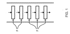
- each filter unit can only handle a certain quantity of fluid before the capacity of the filter unit is reached.
- more filter units may need to be provided.
- each additional filter unit F adds to fluid resistance, thereby necessitating larger fans or pumps to force the fluid through the series of filter units.
- the filter units F are disposed in parallel, such as that shown in FIG. 2, fluid resistance may be kept down but the overall size of the filter assembly grows, sometimes to impractical proportions.
- serial or parallel filter configurations is impractical for the task at hand.
- an object of the present invention is to provide a novel filtration assembly adapted for assembly so as to provide a selected output, and adapted, once in use, for easy modification so as to provide for a changed output requirement.
- Another object of the present invention is to provide a filtration assembly which is adapted for simple, low-cost, mass production, and which includes one or more identical filtration modules, each having an input collection chamber and an output collection chamber for the fluids to be treated, the filtration assembly including a selected number of the identical filtration modules, each filtration module including a filter unit placed within the filtration module, and releasably retained in the module.
- a further object of the present invention is to provide a modular filtration assembly of reduced cost, size, weight, maintenance and set-up, the output of which is determined by a selected number of identical filtration modules, each of the modules being made up of two identical, interconnected L-shaped housing members, arranged in a reversed, head-to-tail configuration, between which are placed one or more mobile cassette-type filter units.
- One of the module housing members directs the input of the fluid to be treated towards the filter unit, and the other module housing member directs the output of the treated fluid from the filter unit.
- Each of the housing members includes two openings, each adapted to flow input and output fluids of each filtration module.
- a feature of the invention is the provision of a low-cost, mass production filtration assembly of minimum size and weight, and reduced set-up and maintenance.
- a further feature of the invention is the provision of such a filtration assembly which includes a selected number of identical filtration modules, each including two identical housing members connectable to one another in a reverse, head-to-tail arrangement, with each housing member having two openings for the fluid being filtered.
- a fluid filtration assembly comprising at least one filtration module, the module comprising first and second identical housing members connectable together in a reverse, head-to-tail arrangement so as to form a recess adapted to receive a filter unit, each of the housing members being provided with a collection chamber having a pair of openings aligned with each other, and a wall portion extending outwardly from the collection chamber and defining one wall of the aforementioned filter recess when the two identical housing members are connected together, the one wall being spaced from the filter unit so as to form a filter input chamber or a filter output chamber (depending on the direction of fluid flow within the fluid filtration module), and wherein the two openings are each adapted to serve as a fluid inlet, the walls permitting fluid flow therebetween and through the filter unit, and the two openings each being further adapted to serve as a fluid outlet, depending on the direction of fluid flow within the fluid filtration module.
- a fluid filtration assembly comprising at least one filtration module, the module comprising a first housing member comprising a first collection chamber in communication with a first wall extending therefrom, the first housing member having a first fluid inlet and a first fluid outlet, respectively, in opposed walls of the first collection chamber and in alignment with each other; a second housing member comprising a second collection chamber in communication with a second wall extending therefrom, the second housing member having a second fluid inlet and a second fluid outlet, respectively, in opposed walls of the second collection chamber and in alignment with each other; the first and second collection chambers and the first and second walls defining a recess for receiving and retaining a filter unit, wherein one of the fluid inlets is open to receive fluid flow and one of the fluid outlets is open to discharge filtered fluid, and wherein the received fluid flows through the fluid inlet, one of the collection chambers, along one of the walls, through the filter, along the other of the walls, through the other of the collection chamber
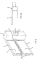
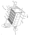
- a housing member A includes a wall 2 and a collection chamber 3.
- the wall 2 is provided with seal members 1 (FIG. 3) which project out of the plane of the wall so as to facilitate forming a filter input chamber 20, or a filter output chamber 20 (FIGS. 4A and 5A), depending on the direction of air flow.
- the collection chamber 3 is provided with a first opening 4 and a second opening 8 aligned with the first opening 4.
- Collection chamber 3 also comprises a third opening 22 adjacent wall 2, whereby fluid can flow between collection chambers 3 and filter input chambers 20 and fluid output chambers 20.
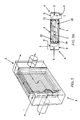
- a pair of identical housing members A are adapted to be connected together in an inverse, head-to-tail configuration, so as to form a filtration module 15 having a recess 13 configured and sized to receive at least one filter unit 6.
- wall 2 and seal members 1 will, in conjunction with the adjacent filter unit 6, form a filter input chamber 20, or a filter output chamber 20, depending on the direction of air flow.
- Each module 15 may be provided with one or more straps 24 and clamp devices 7 to hold the housing members A together and the filter units 6 securely in the recesses 13.
- Each housing member A may further be provided with a spring, such as leaf spring 5, for spreading the various elements apart when straps 24 and clamp devices 7 are released, e.g., such as when needed to remove a filter unit from the module.
- each filtration module 15 is formed by two identical housing members A arranged in an inverse, head-to-tail configuration.
- housing member A only one configuration of housing member A needs to be fabricated in order to form a complete filtration module 15 and, indeed, in order to form a large assembly 14 (FIGS. 6 and 6A) of filtration modules 15.
- manufacturing and inventory issues are greatly simplified and costs dramatically reduced.
- Each of the housing members A is provided with a second opening 8 disposed in alignment with the first opening 4 of the housing member.
- the first openings 4 may serve as inlets 10 or outlets 11 and, as illustrated in FIG. 6A, are engageable with second openings 8 of adjacent housing members.
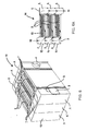
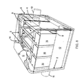
- an assembly 14 (FIGS. 6 and 6A) comprising multiple filtration modules 15, exposed and unused second openings 8 may be covered with a cover plate 9, such that a complete assembly comprising a plurality of filtration modules 15 includes a single inlet 10 and a single outlet 11, with a plurality of essentially parallel paths therebetween.
- the assembly 14 of modules 15 may be placed in a cradle 12, with or without the filter units 6.
- a filtration module 15 having the recess 13, which is adapted to receive one or more of the filter units 6, which may be held together by various tightening devices such as, for example, straps 24 equipped with the clamp devices 7.
- Springs 5 separate the elements when clamps 7 are released.
- Each pair of housing members A configured as shown in FIGS. 4 and 4A, i.e., in inverse, head-to-tail configuration, comprise a filtration module 15, the housing members A being interlocked one into the other, forming the filtration module 15 whose input 10 receives the fluids to be treated, and whose output 11 discharges the treated fluids after being treated by the filter units 6. As shown in FIG.
- a plurality of the modules 15 may be connected together, by way of interfitting of the first openings 4 and the second openings 8, to form a complete, multi-module assembly 14.
- the second opening 8 of both housing members A are closed off, e.g., with plates 9; where multiple modules 15 are to be used in assembly 14, only the two exposed second openings 8 are closed off with plates 9, the remaining second openings 8 being used to provide fluid flow through the various modules 15.
- FIG. 7 there is depicted an example of a filtration assembly 14 made up of five modules 15 which themselves are each made up of two identical housing members A of the type shown in FIG. 3. The number of modules 15 is selected according to the filtration task at hand.
- the cradle 12 is designed to receive the modules.
- FIG. 8 there is illustrated an assembly 14 of three modules 15 mounted in a cradle 12 and prepared for use.
- the number of modules in the assembly can be selected according to the filtration requirements of the user.
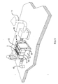
- the cradle 12 can be provided with a support structure S for supporting a coverlet C (only a portion of which is shown in FIG. 8), whereby to shield the assembly 14 from the environment (e.g., rain, snow, etc.).
- the use of the skeleton S and coverlet C provides an inexpensive, easy-to-erect shield which may be quickly and easily removed when desired to provide universal access for unit maintenance, filter replacement and assembly reconfiguration.
- the assembly 14 may be placed on a rooftop 16 (FIG. 9), or other selected location, and provided with appropriate filter units 6.
- air enters the assembly by way of an inlet 10 leading from the interior of the building (not shown) underlying the rooftop 16, passes through three modules 15 simultaneously, and then on to an outlet 11 which serves as a vent to the atmosphere.
- the airflow may be in the opposite direction, i.e., it may enter the assembly through element 11, pass through the filtration assembly and then be introduced into the building through element 10.
- the received fluid flows through one of the collection chambers, along one of the walls, through the filter unit, along the other of the walls, through the other of the collection chambers, and out of the module through the fluid outlet open to discharge fluid.
- the user need only add additional modules to, or remove modules from, the filtration assembly.
- a filtration assembly of filtration modules for filtering fluids, gases or liquids the assembly making available low-cost, mass production of filtration modules of reduced size, weight, maintenance and set-up, and which may easily be combined to provide a multi-filter assembly, with each filter module comprising a plurality of identical, L-shaped housing members connectable to one another in inverse, head-to-tail configuration, each module ensuring the inflow and outflow of fluid in each module and the intake and discharge of the fluids in the assembly.
Landscapes
- Chemical & Material Sciences (AREA)
- Chemical Kinetics & Catalysis (AREA)
- Filtering Of Dispersed Particles In Gases (AREA)
- Separation Using Semi-Permeable Membranes (AREA)
- Lubrication Details And Ventilation Of Internal Combustion Engines (AREA)
- Massaging Devices (AREA)
- Surgical Instruments (AREA)
Applications Claiming Priority (2)
| Application Number | Priority Date | Filing Date | Title |
|---|---|---|---|
| US10/785,200 US7300483B2 (en) | 2004-02-24 | 2004-02-24 | Modular filtration assembly |
| US785200 | 2004-02-24 |
Publications (2)
| Publication Number | Publication Date |
|---|---|
| EP1568405A1 true EP1568405A1 (de) | 2005-08-31 |
| EP1568405B1 EP1568405B1 (de) | 2008-04-16 |
Family
ID=34750465
Family Applications (1)
| Application Number | Title | Priority Date | Filing Date |
|---|---|---|---|
| EP05003641A Expired - Lifetime EP1568405B1 (de) | 2004-02-24 | 2005-02-21 | Modulare Filteranordnung |
Country Status (8)
| Country | Link |
|---|---|
| US (1) | US7300483B2 (de) |
| EP (1) | EP1568405B1 (de) |
| JP (1) | JP2005238231A (de) |
| CN (1) | CN1676189A (de) |
| AT (1) | ATE392247T1 (de) |
| AU (1) | AU2005200599A1 (de) |
| CA (1) | CA2496974A1 (de) |
| DE (1) | DE602005006031D1 (de) |
Cited By (1)
| Publication number | Priority date | Publication date | Assignee | Title |
|---|---|---|---|---|
| EP4091697B1 (de) | 2014-04-07 | 2024-08-28 | Brain Flash-Patententwicklungs GmbH | Set zur reinigung eines luftstroms |
Families Citing this family (18)
| Publication number | Priority date | Publication date | Assignee | Title |
|---|---|---|---|---|
| US20070105494A1 (en) * | 2005-11-08 | 2007-05-10 | Esco Micro Pte Ltd | Ductless fume hood with improved filter monitoring system and extended filter life |
| US7964027B2 (en) * | 2008-02-25 | 2011-06-21 | Antonius Theodorus Cecilianus Hauzer | System for extracting vapor and particulates from a flow of a liquid and an air stream |
| CN102802811B (zh) * | 2009-11-19 | 2016-01-13 | 菲帕克研究及发展公司 | 用于以增大的能量效率操作导管式烟罩的方法和设备 |
| CN103857452A (zh) * | 2011-10-03 | 2014-06-11 | 恩特格里斯公司 | 模块化过滤系统 |
| CN102671440B (zh) * | 2012-05-14 | 2014-06-11 | 宜兴市诺唯环保设备有限公司 | 方形模块式纤维定盘过滤机 |
| EP2698189B1 (de) * | 2012-08-17 | 2019-08-07 | Pall Corporation | Filtermodul und dieses enthaltendes filtersystem |
| PL2698188T3 (pl) * | 2012-08-17 | 2018-05-30 | Pall Corporation | Moduł filtra katalitycznego i zawierający go układ filtra katalitycznego |
| CN104822980A (zh) | 2012-10-01 | 2015-08-05 | 恩特格里斯公司 | 连接系统和方法 |
| CN103263804B (zh) * | 2013-03-22 | 2015-10-07 | 马文晓 | 一种模块组合式快拆反压过滤器 |
| DE102013222301B4 (de) | 2013-11-04 | 2024-01-25 | Dürr Systems Ag | Filteranlage zum Abscheiden von Verunreinigungen aus einem Verunreinigungen enthaltenden Rohgasstrom, Lackieranlage und Verfahren zum Abscheiden von Verunreinigungen aus einem Verunreinigungen enthaltenden Rohgasstrom |
| DE102014010750A1 (de) * | 2014-07-23 | 2016-01-28 | Mann + Hummel Gmbh | System und Filtermodul zur Filterung großer Luftvolumenströme |
| CN104436889A (zh) * | 2014-11-27 | 2015-03-25 | 四川天启智源科技有限公司 | 用于通风系统的板框过滤装置 |
| CN109520043B (zh) * | 2018-12-13 | 2024-04-05 | 深圳市晨北科技有限公司 | 空气净化器 |
| CN109603405A (zh) * | 2019-01-08 | 2019-04-12 | 中铁第四勘察设计院集团有限公司 | 一种冷库变质气体过滤装置 |
| CN112121552A (zh) * | 2019-06-24 | 2020-12-25 | 康宁股份有限公司 | 空气过滤组件 |
| TWI799812B (zh) * | 2020-04-27 | 2023-04-21 | 比利時商亞特拉斯可波克氣動股份有限公司 | 過濾裝置及用於組裝及拆解該過濾裝置的方法 |
| DE202021104100U1 (de) | 2021-07-30 | 2022-11-07 | Ipcs Gmbh Innovative Paint & Conveyor Systems | Filtermodul zur Abscheidung von Overspray aus einer Beschichtungsanlage sowie Vorrichtung zur Abscheidung von Overspray |
| CN113579949A (zh) * | 2021-09-28 | 2021-11-02 | 湖南致用科技有限公司 | 一种多维度焊接点抛光的打磨机床 |
Citations (4)
| Publication number | Priority date | Publication date | Assignee | Title |
|---|---|---|---|---|
| DE9102485U1 (de) * | 1991-03-02 | 1991-05-23 | Heissner GmbH, 6420 Lauterbach | Kassetten-Filter |
| FR2803534A1 (fr) * | 2000-01-11 | 2001-07-13 | Fipak Res & Dev Co | Unite de filtration d'air pollue de grand debit de faible encombrement fonctionnant en depression ou en pression simplifiant la conception des filtres et permettant le montage et le demontage desdits filtres avec facilite |
| US20020074277A1 (en) * | 2000-11-24 | 2002-06-20 | Membrane Concepts, S.L. | Filter assembly, system and method for filtering fluids |
| DE10140081A1 (de) * | 2001-08-16 | 2003-03-06 | Iww Inst Fuer Wasserforschung | Filtermodul |
Family Cites Families (3)
| Publication number | Priority date | Publication date | Assignee | Title |
|---|---|---|---|---|
| US2143270A (en) * | 1936-08-13 | 1939-01-10 | Tuthill Pump Co | Strainer |
| CA1098045A (en) * | 1976-10-14 | 1981-03-24 | William J. Schnell | Dialyzer casing |
| DE4141823C2 (de) * | 1991-12-18 | 1994-12-15 | Mann & Hummel Filter | Flüssigkeitsfilter |
-
2004
- 2004-02-24 US US10/785,200 patent/US7300483B2/en not_active Expired - Lifetime
-
2005
- 2005-02-11 AU AU2005200599A patent/AU2005200599A1/en not_active Abandoned
- 2005-02-14 CA CA002496974A patent/CA2496974A1/en not_active Abandoned
- 2005-02-18 JP JP2005041677A patent/JP2005238231A/ja active Pending
- 2005-02-21 AT AT05003641T patent/ATE392247T1/de not_active IP Right Cessation
- 2005-02-21 DE DE602005006031T patent/DE602005006031D1/de not_active Expired - Lifetime
- 2005-02-21 EP EP05003641A patent/EP1568405B1/de not_active Expired - Lifetime
- 2005-02-24 CN CN200510050971.8A patent/CN1676189A/zh active Pending
Patent Citations (4)
| Publication number | Priority date | Publication date | Assignee | Title |
|---|---|---|---|---|
| DE9102485U1 (de) * | 1991-03-02 | 1991-05-23 | Heissner GmbH, 6420 Lauterbach | Kassetten-Filter |
| FR2803534A1 (fr) * | 2000-01-11 | 2001-07-13 | Fipak Res & Dev Co | Unite de filtration d'air pollue de grand debit de faible encombrement fonctionnant en depression ou en pression simplifiant la conception des filtres et permettant le montage et le demontage desdits filtres avec facilite |
| US20020074277A1 (en) * | 2000-11-24 | 2002-06-20 | Membrane Concepts, S.L. | Filter assembly, system and method for filtering fluids |
| DE10140081A1 (de) * | 2001-08-16 | 2003-03-06 | Iww Inst Fuer Wasserforschung | Filtermodul |
Cited By (1)
| Publication number | Priority date | Publication date | Assignee | Title |
|---|---|---|---|---|
| EP4091697B1 (de) | 2014-04-07 | 2024-08-28 | Brain Flash-Patententwicklungs GmbH | Set zur reinigung eines luftstroms |
Also Published As
| Publication number | Publication date |
|---|---|
| US7300483B2 (en) | 2007-11-27 |
| CA2496974A1 (en) | 2005-08-24 |
| US20050184005A1 (en) | 2005-08-25 |
| JP2005238231A (ja) | 2005-09-08 |
| DE602005006031D1 (de) | 2008-05-29 |
| CN1676189A (zh) | 2005-10-05 |
| ATE392247T1 (de) | 2008-05-15 |
| EP1568405B1 (de) | 2008-04-16 |
| AU2005200599A1 (en) | 2005-09-08 |
Similar Documents
| Publication | Publication Date | Title |
|---|---|---|
| EP1568405A1 (de) | Modular filtration assembly | |
| US8636903B2 (en) | Hydraulic filter with one-piece input end cap | |
| US20080011672A1 (en) | Direct Flow Filter Including Auxiliary Filter | |
| EP2977091A1 (de) | Modulares filtersystem, gehäuserahmenteil eines modularen filtersystems, filtermodul und gehäusemodul | |
| GB2063098A (en) | Filter element for filtering compressed air | |
| US20060277875A1 (en) | Stackable air purifier system with expandable housing | |
| US5984991A (en) | High-efficiency air filter | |
| WO2007046946A2 (en) | Multi-element filter with multiple pleat channel height | |
| KR20140064663A (ko) | 기계적으로 밀봉된 플리트 팩을 구비한 역방향 v셀 또는 미니플리트 필터 | |
| CN104487151B (zh) | 过滤器滤芯 | |
| CN115155166A (zh) | 过滤密封系统 | |
| WO2020047437A1 (en) | Systems, devices, and methods for cyclonic filtration | |
| US20030230059A1 (en) | Filter system employing microwave regeneration | |
| CN214536473U (zh) | 空调器 | |
| KR100761750B1 (ko) | 필터를 갖는 공기 압축기 | |
| KR102920019B1 (ko) | 필터조립체 | |
| CN108644930B (zh) | 一种空气净化器 | |
| CN105167714A (zh) | 吸尘器 | |
| CN220815850U (zh) | 过滤器总成 | |
| EP4190427B1 (de) | Filtervorrichtung | |
| EP0466456B1 (de) | Filteranlage | |
| RU2070429C1 (ru) | Фильтрующий элемент | |
| CN121368500A (zh) | 具有在过滤介质体凹部中的把手元件的过滤元件以及具有此类过滤元件的过滤装置 | |
| JP2876921B2 (ja) | 濾過器 | |
| JP2000084312A (ja) | 濾過エレメント |
Legal Events
| Date | Code | Title | Description |
|---|---|---|---|
| PUAI | Public reference made under article 153(3) epc to a published international application that has entered the european phase |
Free format text: ORIGINAL CODE: 0009012 |
|
| AK | Designated contracting states |
Kind code of ref document: A1 Designated state(s): AT BE BG CH CY CZ DE DK EE ES FI FR GB GR HU IE IS IT LI LT LU MC NL PL PT RO SE SI SK TR |
|
| AX | Request for extension of the european patent |
Extension state: AL BA HR LV MK YU |
|
| 17P | Request for examination filed |
Effective date: 20060222 |
|
| AKX | Designation fees paid |
Designated state(s): AT BE BG CH CY CZ DE DK EE ES FI FR GB GR HU IE IS IT LI LT LU MC NL PL PT RO SE SI SK TR |
|
| 17Q | First examination report despatched |
Effective date: 20060327 |
|
| 17Q | First examination report despatched |
Effective date: 20060327 |
|
| GRAP | Despatch of communication of intention to grant a patent |
Free format text: ORIGINAL CODE: EPIDOSNIGR1 |
|
| RTI1 | Title (correction) |
Free format text: MODULAR FILTRATION ASSEMBLY |
|
| GRAS | Grant fee paid |
Free format text: ORIGINAL CODE: EPIDOSNIGR3 |
|
| GRAA | (expected) grant |
Free format text: ORIGINAL CODE: 0009210 |
|
| AK | Designated contracting states |
Kind code of ref document: B1 Designated state(s): AT BE BG CH CY CZ DE DK EE ES FI FR GB GR HU IE IS IT LI LT LU MC NL PL PT RO SE SI SK TR |
|
| REG | Reference to a national code |
Ref country code: CH Ref legal event code: EP |
|
| REG | Reference to a national code |
Ref country code: IE Ref legal event code: FG4D |
|
| REF | Corresponds to: |
Ref document number: 602005006031 Country of ref document: DE Date of ref document: 20080529 Kind code of ref document: P |
|
| PG25 | Lapsed in a contracting state [announced via postgrant information from national office to epo] |
Ref country code: SI Free format text: LAPSE BECAUSE OF FAILURE TO SUBMIT A TRANSLATION OF THE DESCRIPTION OR TO PAY THE FEE WITHIN THE PRESCRIBED TIME-LIMIT Effective date: 20080416 |
|
| NLV1 | Nl: lapsed or annulled due to failure to fulfill the requirements of art. 29p and 29m of the patents act | ||
| PG25 | Lapsed in a contracting state [announced via postgrant information from national office to epo] |
Ref country code: FI Free format text: LAPSE BECAUSE OF FAILURE TO SUBMIT A TRANSLATION OF THE DESCRIPTION OR TO PAY THE FEE WITHIN THE PRESCRIBED TIME-LIMIT Effective date: 20080416 Ref country code: PT Free format text: LAPSE BECAUSE OF FAILURE TO SUBMIT A TRANSLATION OF THE DESCRIPTION OR TO PAY THE FEE WITHIN THE PRESCRIBED TIME-LIMIT Effective date: 20080916 Ref country code: NL Free format text: LAPSE BECAUSE OF FAILURE TO SUBMIT A TRANSLATION OF THE DESCRIPTION OR TO PAY THE FEE WITHIN THE PRESCRIBED TIME-LIMIT Effective date: 20080416 Ref country code: BG Free format text: LAPSE BECAUSE OF FAILURE TO SUBMIT A TRANSLATION OF THE DESCRIPTION OR TO PAY THE FEE WITHIN THE PRESCRIBED TIME-LIMIT Effective date: 20080716 Ref country code: ES Free format text: LAPSE BECAUSE OF FAILURE TO SUBMIT A TRANSLATION OF THE DESCRIPTION OR TO PAY THE FEE WITHIN THE PRESCRIBED TIME-LIMIT Effective date: 20080727 |
|
| PG25 | Lapsed in a contracting state [announced via postgrant information from national office to epo] |
Ref country code: AT Free format text: LAPSE BECAUSE OF FAILURE TO SUBMIT A TRANSLATION OF THE DESCRIPTION OR TO PAY THE FEE WITHIN THE PRESCRIBED TIME-LIMIT Effective date: 20080416 Ref country code: PL Free format text: LAPSE BECAUSE OF FAILURE TO SUBMIT A TRANSLATION OF THE DESCRIPTION OR TO PAY THE FEE WITHIN THE PRESCRIBED TIME-LIMIT Effective date: 20080416 |
|
| PG25 | Lapsed in a contracting state [announced via postgrant information from national office to epo] |
Ref country code: IS Free format text: LAPSE BECAUSE OF FAILURE TO SUBMIT A TRANSLATION OF THE DESCRIPTION OR TO PAY THE FEE WITHIN THE PRESCRIBED TIME-LIMIT Effective date: 20080816 |
|
| PG25 | Lapsed in a contracting state [announced via postgrant information from national office to epo] |
Ref country code: SE Free format text: LAPSE BECAUSE OF FAILURE TO SUBMIT A TRANSLATION OF THE DESCRIPTION OR TO PAY THE FEE WITHIN THE PRESCRIBED TIME-LIMIT Effective date: 20080716 Ref country code: LT Free format text: LAPSE BECAUSE OF FAILURE TO SUBMIT A TRANSLATION OF THE DESCRIPTION OR TO PAY THE FEE WITHIN THE PRESCRIBED TIME-LIMIT Effective date: 20080416 Ref country code: CZ Free format text: LAPSE BECAUSE OF FAILURE TO SUBMIT A TRANSLATION OF THE DESCRIPTION OR TO PAY THE FEE WITHIN THE PRESCRIBED TIME-LIMIT Effective date: 20080416 Ref country code: DK Free format text: LAPSE BECAUSE OF FAILURE TO SUBMIT A TRANSLATION OF THE DESCRIPTION OR TO PAY THE FEE WITHIN THE PRESCRIBED TIME-LIMIT Effective date: 20080416 |
|
| PLBE | No opposition filed within time limit |
Free format text: ORIGINAL CODE: 0009261 |
|
| STAA | Information on the status of an ep patent application or granted ep patent |
Free format text: STATUS: NO OPPOSITION FILED WITHIN TIME LIMIT |
|
| EN | Fr: translation not filed | ||
| PG25 | Lapsed in a contracting state [announced via postgrant information from national office to epo] |
Ref country code: BE Free format text: LAPSE BECAUSE OF FAILURE TO SUBMIT A TRANSLATION OF THE DESCRIPTION OR TO PAY THE FEE WITHIN THE PRESCRIBED TIME-LIMIT Effective date: 20080416 Ref country code: SK Free format text: LAPSE BECAUSE OF FAILURE TO SUBMIT A TRANSLATION OF THE DESCRIPTION OR TO PAY THE FEE WITHIN THE PRESCRIBED TIME-LIMIT Effective date: 20080416 Ref country code: RO Free format text: LAPSE BECAUSE OF FAILURE TO SUBMIT A TRANSLATION OF THE DESCRIPTION OR TO PAY THE FEE WITHIN THE PRESCRIBED TIME-LIMIT Effective date: 20080416 |
|
| 26N | No opposition filed |
Effective date: 20090119 |
|
| PG25 | Lapsed in a contracting state [announced via postgrant information from national office to epo] |
Ref country code: DE Free format text: LAPSE BECAUSE OF FAILURE TO SUBMIT A TRANSLATION OF THE DESCRIPTION OR TO PAY THE FEE WITHIN THE PRESCRIBED TIME-LIMIT Effective date: 20080717 Ref country code: EE Free format text: LAPSE BECAUSE OF FAILURE TO SUBMIT A TRANSLATION OF THE DESCRIPTION OR TO PAY THE FEE WITHIN THE PRESCRIBED TIME-LIMIT Effective date: 20080416 |
|
| PG25 | Lapsed in a contracting state [announced via postgrant information from national office to epo] |
Ref country code: IT Free format text: LAPSE BECAUSE OF FAILURE TO SUBMIT A TRANSLATION OF THE DESCRIPTION OR TO PAY THE FEE WITHIN THE PRESCRIBED TIME-LIMIT Effective date: 20080416 |
|
| PG25 | Lapsed in a contracting state [announced via postgrant information from national office to epo] |
Ref country code: MC Free format text: LAPSE BECAUSE OF NON-PAYMENT OF DUE FEES Effective date: 20090228 Ref country code: CY Free format text: LAPSE BECAUSE OF FAILURE TO SUBMIT A TRANSLATION OF THE DESCRIPTION OR TO PAY THE FEE WITHIN THE PRESCRIBED TIME-LIMIT Effective date: 20080416 |
|
| REG | Reference to a national code |
Ref country code: CH Ref legal event code: PL |
|
| GBPC | Gb: european patent ceased through non-payment of renewal fee |
Effective date: 20090221 |
|
| PG25 | Lapsed in a contracting state [announced via postgrant information from national office to epo] |
Ref country code: LI Free format text: LAPSE BECAUSE OF NON-PAYMENT OF DUE FEES Effective date: 20090228 Ref country code: CH Free format text: LAPSE BECAUSE OF NON-PAYMENT OF DUE FEES Effective date: 20090228 |
|
| PG25 | Lapsed in a contracting state [announced via postgrant information from national office to epo] |
Ref country code: IE Free format text: LAPSE BECAUSE OF NON-PAYMENT OF DUE FEES Effective date: 20090223 |
|
| PG25 | Lapsed in a contracting state [announced via postgrant information from national office to epo] |
Ref country code: GB Free format text: LAPSE BECAUSE OF NON-PAYMENT OF DUE FEES Effective date: 20090221 |
|
| PG25 | Lapsed in a contracting state [announced via postgrant information from national office to epo] |
Ref country code: GR Free format text: LAPSE BECAUSE OF FAILURE TO SUBMIT A TRANSLATION OF THE DESCRIPTION OR TO PAY THE FEE WITHIN THE PRESCRIBED TIME-LIMIT Effective date: 20080717 |
|
| PG25 | Lapsed in a contracting state [announced via postgrant information from national office to epo] |
Ref country code: LU Free format text: LAPSE BECAUSE OF NON-PAYMENT OF DUE FEES Effective date: 20090221 |
|
| PG25 | Lapsed in a contracting state [announced via postgrant information from national office to epo] |
Ref country code: HU Free format text: LAPSE BECAUSE OF FAILURE TO SUBMIT A TRANSLATION OF THE DESCRIPTION OR TO PAY THE FEE WITHIN THE PRESCRIBED TIME-LIMIT Effective date: 20081017 |
|
| PG25 | Lapsed in a contracting state [announced via postgrant information from national office to epo] |
Ref country code: TR Free format text: LAPSE BECAUSE OF FAILURE TO SUBMIT A TRANSLATION OF THE DESCRIPTION OR TO PAY THE FEE WITHIN THE PRESCRIBED TIME-LIMIT Effective date: 20080416 |
|
| PG25 | Lapsed in a contracting state [announced via postgrant information from national office to epo] |
Ref country code: FR Free format text: LAPSE BECAUSE OF FAILURE TO SUBMIT A TRANSLATION OF THE DESCRIPTION OR TO PAY THE FEE WITHIN THE PRESCRIBED TIME-LIMIT Effective date: 20090227 |