EP4091421A1 - Erntemaschine mit tankerweiterung - Google Patents
Erntemaschine mit tankerweiterung Download PDFInfo
- Publication number
- EP4091421A1 EP4091421A1 EP22155901.6A EP22155901A EP4091421A1 EP 4091421 A1 EP4091421 A1 EP 4091421A1 EP 22155901 A EP22155901 A EP 22155901A EP 4091421 A1 EP4091421 A1 EP 4091421A1
- Authority
- EP
- European Patent Office
- Prior art keywords
- harvesting machine
- tank
- machine according
- access flap
- access
- Prior art date
- Legal status (The legal status is an assumption and is not a legal conclusion. Google has not performed a legal analysis and makes no representation as to the accuracy of the status listed.)
- Granted
Links
Images


Classifications
-
- A—HUMAN NECESSITIES
- A01—AGRICULTURE; FORESTRY; ANIMAL HUSBANDRY; HUNTING; TRAPPING; FISHING
- A01D—HARVESTING; MOWING
- A01D41/00—Combines, i.e. harvesters or mowers combined with threshing devices
- A01D41/12—Details of combines
-
- A—HUMAN NECESSITIES
- A01—AGRICULTURE; FORESTRY; ANIMAL HUSBANDRY; HUNTING; TRAPPING; FISHING
- A01D—HARVESTING; MOWING
- A01D41/00—Combines, i.e. harvesters or mowers combined with threshing devices
- A01D41/12—Details of combines
- A01D41/1208—Tanks for grain or chaff
- A01D41/1226—Extension mechanisms
-
- A—HUMAN NECESSITIES
- A01—AGRICULTURE; FORESTRY; ANIMAL HUSBANDRY; HUNTING; TRAPPING; FISHING
- A01D—HARVESTING; MOWING
- A01D41/00—Combines, i.e. harvesters or mowers combined with threshing devices
- A01D41/12—Details of combines
- A01D41/1208—Tanks for grain or chaff
-
- A—HUMAN NECESSITIES
- A01—AGRICULTURE; FORESTRY; ANIMAL HUSBANDRY; HUNTING; TRAPPING; FISHING
- A01D—HARVESTING; MOWING
- A01D41/00—Combines, i.e. harvesters or mowers combined with threshing devices
- A01D41/12—Details of combines
- A01D41/1261—Access devices for personnel
-
- A—HUMAN NECESSITIES
- A01—AGRICULTURE; FORESTRY; ANIMAL HUSBANDRY; HUNTING; TRAPPING; FISHING
- A01F—PROCESSING OF HARVESTED PRODUCE; HAY OR STRAW PRESSES; DEVICES FOR STORING AGRICULTURAL OR HORTICULTURAL PRODUCE
- A01F12/00—Parts or details of threshing apparatus
- A01F12/60—Grain tanks
Definitions
- the present invention relates to a harvesting machine, in particular a combine harvester, whose harvested crop tank comprises a tank extension formed from a number of movable elements.
- a combine harvester is out DE 10 2004 007 673 A1 known.
- the crop tank of this combine includes a rigid-walled lower portion that is incorporated into the body of the combine, and a tank extension includes a plurality of plate-like members that pivot about axes running along an upper edge of the lower portion between a rest position covering the lower portion and an erected operative position are.
- JP2019004784 proposed to provide a flap in a side wall of the body of the combine harvester, which a user can open to climb into the grain tank. Climbing through such a flap is very tedious and uncomfortable when the small size of the flap makes it necessary to climb through it on all fours and there is no suitable surface in front of and behind the flap to provide support for hands and knees.
- the object of the invention is to create a harvesting machine that enables a user to easily and conveniently enter the harvested crop tank.
- the object is achieved in that in a harvesting machine with a harvested crop tank, which comprises a tank extension formed from several movable elements, at least one access flap is assigned to at least one of the elements, which in an open position gives a user access to the interior of the harvested crop tank.
- An upper body of the harvester can serve as a base that supports the user in the vicinity of the access door.
- the access door should fill a passage of the at least one element in a closed position.
- the access door is in the open position within the crop tank.
- the flap opening inwards ensures that it is blocked by the contents when the tank is full. Therefore, no tank content can escape if the flap is opened at the wrong time.
- the passage is preferably a section of the tank extension that is open at the top. This allows the user to get in and out of the crop tank in an upright position.
- the cutout is preferably formed in precisely one of the movable elements, and parts of the one movable element lying on different sides of the cutout are connected to one another in a rotationally fixed manner.
- the parts of the movable element lying on different sides of the cutout cannot pivot independently of one another, which is important for the mechanical stability of the tank extension.
- the access flap may have a stiffening profile extending along its upper edge to withstand the pressure of crop in the tank without appreciable deflection. Similar stiffening profiles can also be provided on the movable elements, such that the gusset of the access panel fills adjacent gussets in a gap between the gussets of the movable members in the closed position of the access panel.
- the stiffening profile of the access flap should be in engagement with at least one stiffening profile of the movable elements so that it can withstand tensile loads in its longitudinal direction. If the access panel is pivotable about a lateral axis, then a hinge on that side forms a tensile connection between the access panel and an adjacent portion of the moveable member, and it is sufficient if the stiffening profile is tensilely engaged on the opposite side. However, a pivot axis of the flap can also run along its lower edge facing away from the stiffening profile; in this case, the tension-loadable engagement should be given at both ends of the stiffening profile of the flap.
- Means may be provided for locking the access panel in the open position, preferably pivoted about 90° from the closed position.
- its stiffening profile can act as a sort of handle or railing facilitating entry and exit from the crop tank.
- the movable elements can be pivoted about horizontal axes between a rest position in which they cover a lower part of the crop tank and a use position in which they diverge upwards from the axes.
- This inclined position of the movable elements makes it particularly difficult to climb over the movable elements, so that the access flap according to the invention is particularly advantageous here.
- the access door according to the invention is particularly effective in the case of movable elements of such a size that pairs of the movable elements which, in the position of use, face each other on either side of the tank extension, overlap at least partially in the position of rest.
- a ladder should be provided to allow a user to enter a lower portion of the crop tank.
- Such a ladder may be mounted in a lower portion of the crop tank leading to the access door.
- the ladder can also be integrated into the access flap;
- the access flap can be pivoted about an axis running along its lower edge, the ladder can be provided on the side of the access flap which is on the outside when it is in the closed position and, by opening and pivoting the access flap into the grain tank, it reaches a position in which the ladder is in into the lower part of the tank and can be used.
- a harvesting attachment 1 and threshing and cleaning elements 2, 3 of the combine harvester are of a known type and do not need to be described here.
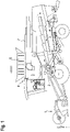
- a crop tank 4, which accommodates the threshed and cleaned grain, comprises a lower part 5, which is housed within a body of the combine harvester, and a tank extension 6, which in its position of use shown in the figure protrudes above an upper side 7 of the body.
- FIG. 1 Side walls of the tank extension 6 are separated by a plurality of in Figures 2 and 3 visible, rigid in itself plate-shaped movable elements 8-11, which are pivotally connected to the bodywork around axes extending along their lower edges at the level of the top 7 and face each other in pairs.
- the movable elements 8, 9 of a pair are trapezoidal, with the longer of the two base lines of the trapezium forming the lower edge of the element 8 or 9, respectively.
- the movable elements 10, 11 of another pair are rectangular. Spaces between a sloping side of one of the elements 8, 9 and a shorter side of one of the elements 10, 11 are filled by flexible triangular tarpaulins 12 which are foldably connected to the adjacent movable elements 8-11 along edges 13, respectively.
- This construction allows the tank extension 6 to go into a rest configuration by pivoting the mobile elements 8-11 towards each other up to a horizontal position in which they close the lower part 5 upwards and the opposite mobile elements 8 and 9 or 10 and 11 overlap each other.
- the upper side 7 comprises a walk-in area 14 and an element 15 which can be switched between a position flush with the walk-in area and a position in Figures 2 and 3 shown upright position is pivotable.
- the element 15 can be locked in the upright position in order to provide support for a user who is on the walk-on area 14 .
- a cutout 16 that is open at the top is formed. Parts 17, 18 on opposite sides of the cutout 16 are rigidly connected to one another by a web 19 running under the cutout 16.
- FIG. An access flap 20 is hinged to portion 18 along a lateral edge 21 of cutout 16 .
- Figures 2 and 3 12 show the access panel 20 in an open position pivoted about 90° from the plane of the movable element 8.
- FIG. The access panel 20 is fixable in the open position by means not shown in the figure.
- FIG 4 shows a closed position of the access flap 20.
- a lateral edge area 22 of the access flap 20 lies on an edge web 24 of the part 17 (see 3 ) on.
- the access panel 20 can only pivot inwardly of the tank extension 6 from the closed position; it is not possible for the access flap 20 to spring open under the pressure of crops lying on it.
- a handle bar 23 at the top of element 15 provides support for the user on the way to cutout 16; behind the cut-out 16 he can cling to a stiffening profile 25 forming an upper edge of the access flap 20, like a railing.
- first step 26 on the inside of the web 19, which the user can step on after passing the cutout.
- extends underneath a ladder 27 allowing him to descend into the lower part 5 of the crop tank 4.
- Upper ends 28 of the ladder 27 are fixed to a wall of the lower part 5; the ladder 27 therefore remains in place when the tank extension 6 is transferred to the rest position.
- figure 5 shows a schematic longitudinal section through the stiffening profile 25, a subsequent stiffening profile 29 of the movable element 8 and a tensile belt 30, which forms an upper edge of a triangular tarpaulin 12 adjoining it.
- a barb 31 is formed on an end of the stiffening profile 25 that is remote from the hinge.
- the barb 31 freely engages a hole 32 or recess of the stiffening profile section 29 as shown and is free to exit again when the access panel 20 is opened. If, on the other hand, the movable elements 8-11 are pushed apart by the weight of crops in the tank extension 6, then the stiffening profiles 25, 29 are also pulled apart longitudinally. In this case, the barb 31 engages behind an edge of the hole 32 or in an undercut of the recess.
- the stiffening profile 25 prevents the movable element 8, which is weakened by the cutout 16, from bending under the load of the tank contents and its parts 17, 18 from being pulled apart, on the other hand it makes it more difficult to open the access flap 20 in a thoroughly desirable manner when the tank expansion 6 is not empty.
- the access flap 20 can be pivoted about an axis running along its lower edge instead of about a lateral axis.
- Level 26 is omitted here, instead comes in the open position, a part of the access flap 20 close to the axis on the inside of the web 19 to rest; a part away from the axis protrudes beyond the web 19 into the lower part 5 of the crop tank 4.
- steps are provided which enable the user to easily descend into the lower part 5.
Landscapes
- Life Sciences & Earth Sciences (AREA)
- Environmental Sciences (AREA)
- Outside Dividers And Delivering Mechanisms For Harvesters (AREA)
- Threshing Machine Elements (AREA)
- Harvester Elements (AREA)
Abstract
Description
- Die vorliegende Erfindung betrifft eine Erntemaschine, insbesondere einen Mähdrescher, deren Ernteguttank eine aus mehreren beweglichen Elementen gebildete Tankerweiterung umfasst. Eine solcher Mähdrescher ist aus
DE 10 2004 007 673 A1 bekannt. Der Ernteguttank dieses Mähdreschers umfasst einen starrwandigen unteren Teil, der in die Karosserie des Mähdreschers einbezogen ist, und eine Tankerweiterung umfasst mehrere plattenförmige Elemente, die um entlang eines oberen Randes des unteren Teils verlaufende Achsen zwischen einer den unteren Teil überdeckenden Ruhestellung und einer aufgerichteten Betriebsstellung schwenkbar sind. - Um Wartungsarbeiten im Innern des Korntanks eines Mähdreschers durchführen zu können, ist in
JP2019004784 - Aufgabe der Erfindung ist, eine Erntemaschine zu schaffen, die einem Benutzer einen einfachen und bequemen Einstieg in den Ernteguttank ermöglicht.
- Die Aufgabe wird gelöst, indem bei einer Erntemaschine mit einem Ernteguttank, der eine aus mehreren beweglichen Elementen gebildete Tankerweiterung umfasst, wenigstens einem der Elemente wenigstens eine Zugangsklappe zugeordnet ist, die in einer offenen Stellung einem Benutzer Zugang zum Innern des Ernteguttanks gewährt. Als Unterlage, die den Benutzer in der Nähe der Zugangsklappe trägt, kann hier eine Karosserieoberseite der Erntemaschine dienen.
- Die Zugangsklappe sollte in einer geschlossenen Stellung einen Durchgang des wenigstens einen Elements ausfüllen.
- Vorzugsweise befindet sich die Zugangsklappe in der offenen Stellung innerhalb des Ernteguttanks. Indem die Klappe nach innen aufgeht, ist sichergestellt, dass sie bei vollem Tank durch dessen Inhalt blockiert wird. Daher kann kein Tankinhalt austreten, wenn die Klappe zur Unzeit geöffnet wird.
- Der Durchgang ist vorzugsweise ein nach oben offener Ausschnitt der Tankerweiterung. Dies ermöglicht es dem Benutzer, in aufrechter Körperhaltung in den Ernteguttank ein- und wieder herauszusteigen.
- Vorzugsweise ist der Ausschnitt in genau einem der beweglichen Elemente gebildet, und auf verschiedenen Seiten des Ausschnitts liegende Teile des einen beweglichen Elements sind untereinander drehfest verbunden. So können die verschiedenen Seiten des Ausschnitts liegenden Teile des beweglichen Elements nicht unabhängig voneinander schwenken, was für die mechanische Stabilität der Tankerweiterung wichtig ist.
- Die Zugangsklappe kann ein sich entlang ihrer oberen Kante erstreckendes Versteifungsprofil aufweisen, um dem Druck von Erntegut im Tank ohne nennenswerte Durchbiegung standhalten zu können. Ähnliche Versteifungsprofile können auch an den beweglichen Elementen vorgesehen sein, so dass das Versteifungsprofil der Zugangsklappe in der geschlossenen Stellung der Zugangsklappe angrenzende Versteifungsprofile eine Lücke zwischen den Versteifungsprofilen der beweglichen Elemente ausfüllt.
- Um Druck des Tankinhalts sicher standhalten zu können, sollte das Versteifungsprofil der Zugangsklappe in seiner Längsrichtung zugbelastbar mit wenigstens einem Versteifungsprofil der beweglichen Elemente in Eingriff sein. Wenn die Zugangsklappe um eine seitliche Achse schwenkbar ist, dann an dieser Seite ein Scharnier eine zugbelastbare Verbindung zwischen der Zugangsklappe und einem angrenzenden Bereich des beweglichen Elements bilden, und es genügt, wenn das Versteifungsprofil an der gegenüberliegenden Seite zugbelastbar in Eingriff ist. Eine Schwenkachse der Klappe kann aber auch entlang deren vom Versteifungsprofil abgewandter unterer Kante verlaufen; in diesem Fall sollte der zugbelastbare Eingriff an beiden Enden des Versteifungsprofils der Klappe gegeben sein.
- Es können Mittel zum Fixieren der Zugangsklappe in der offenen Stellung, vorzugsweise um ca. 90° gegen die geschlossene Stellung geschwenkt, vorgesehen sein. Wenn die Zugangsklappe in dieser Weise fixiert ist, kann ihr Versteifungsprofil als eine Art Handgriff oder Geländer fungieren, das den Ein- und Ausstieg aus dem Ernteguttank erleichtert.
- Die beweglichen Elemente können zwischen einer Ruhestellung, in der sie einen unteren Teil des Ernteguttanks überdecken, um horizontale Achsen in eine Gebrauchsstellung schwenkbar sein, in der sie von den Achsen aus nach oben divergieren. Diese schräge Stellung der beweglichen Elemente macht ein Übersteigen der beweglichen Elemente besonders schwierig, so dass gerade hier die erfindungsgemäße Zugangsklappe besonders vorteilhaft ist.
- Je größer die beweglichen Elemente sind, umso schwieriger ist ein Übersteigen. Daher ist die erfindungsgemäße Zugangsklappe besonders wirksam bei beweglichen Elementen, die so groß sind, dass Paare der beweglichen Elemente, die einander in der Gebrauchsstellung beiderseits der Tankerweiterung gegenüberliegen, in der Ruhestellung wenigstens teilweise überlappen.
- Um einem Benutzer das Einsteigen in einen unteren Teil des Ernteguttanks zu ermöglichen, sollte eine Leiter vorgesehen sein.
- Eine solche Leiter kann in einem unteren Teil des Ernteguttanks zur Zugangsklappe führend montiert sein.
- Einer alternativen Ausgestaltung zufolge kann die Leiter auch in die Zugangsklappe integriert sein; insbesondere wenn die Zugangsklappe um eine entlang ihrer Unterkante verlaufende Achse schwenkbar ist, kann die Leiter an der in der geschlossenen Stellung außenliegenden Seite der Zugangsklappe vorgesehen sein und gelangt durch das Öffnen und Hineinschwenken der Zugangsklappe in den Korntank in eine Stellung, in der die Leiter in den unteren Teil des Tanks hineinführt und benutzt werden kann.
- Weitere Merkmale und Vorteile der Erfindung ergeben sich aus der nachfolgenden Beschreibung von Ausführungsbeispielen unter Bezugnahme auf die beigefügten Figuren. Es zeigen:
- Fig. 1
- eine Seitenansicht eines erfindungsgemäßen Mähdreschers;
- Fig. 2
- eine perspektivische Außenansicht einer Tankerweiterung des Mähdreschers;
- Fig. 3
- eine perspektivische Innenansicht der Tankerweiterung;
- Fig. 4
- eine Detailansicht der Tankerweiterung bei geschlossener Zugangsklappe; und
- Fig. 5
- einen schematischen Längsschnitt von Versteifungsprofilen der Zugangsklappe und eines die Zugangsklappe aufnehmenden beweglichen Elements.
-
Fig. 1 zeigt teils in Seitenansicht, teils im Schnitt einen Mähdrescher als Beispiel einer erfindungsgemäßen Erntemaschine. Ein Erntevorsatz 1 sowie Dresch- und Reinigungsorgane 2, 3 des Mähdreschers sind von an sich bekannter Bauart und brauchen an dieser Stelle nicht beschrieben zu werden. Ein Ernteguttank 4, der das gedroschene und gereinigte Korn aufnimmt, umfasst einen unteren Teil 5, der innerhalb einer Karosserie des Mähdreschers untergebracht ist, sowie eine Tankerweiterung 6, die in ihrer in der Fig. gezeigten Gebrauchsstellung über eine Oberseite 7 der Karosserie aufragt. - Seitenwände der Tankerweiterung 6 sind durch eine Mehrzahl von in
Fig. 2 und 3 sichtbaren, in sich steifen plattenförmigen beweglichen Elementen 8-11 gebildet, die jeweils um entlang ihrer Unterkanten in Höhe der Oberseite 7 verlaufende Achsen schwenkbar mit der Karosserie verbunden sind und einander paarweise gegenüberliegen. Die beweglichen Elemente, 8, 9 eines Paars sind trapezförmig, wobei die längere der beiden Grundlinien des Trapezes die untere Kante des Elements 8 bzw. 9 bildet. Die beweglichen Elemente, 10, 11 eines weiteren Paars sind rechteckig. Zwischenräume zwischen einer schrägen Seite eines der Elemente 8, 9 und einer kürzeren Seite eines der Elemente 10, 11 sind durch flexible dreieckige Planen 12 ausgefüllt, die mit den angrenzenden beweglichen Elementen 8-11 jeweils entlang von Kanten 13 faltbar verbunden sind. Dieser Aufbau ermöglicht es der Tankerweiterung 6, in eine Ruhekonfiguration überzugehen, indem die beweglichen Elemente 8-11 zueinander hin bis in eine horizontale Stellung geschwenkt werden, in der sie den unteren Teil 5 nach oben verschließen und die einander gegenüberliegenden beweglichen Elemente 8 und 9 bzw. 10 und 11 miteinander überlappen. - Die Oberseite 7 umfasst einen begehbaren Bereich 14 sowie ein Element 15, das zwischen einer mit dem begehbaren Bereich bündigen Stellung und einer in
Fig. 2 und 3 gezeigten aufrechten Stellung schwenkbar ist. In der aufrechten Stellung ist das Element 15 arretierbar, um einem Benutzer, der sich auf dem begehbaren Bereich 14 aufhält, Halt zu bieten. - In dem an den begehbaren Bereich 14 angrenzenden beweglichen Element 8 ist ein nach oben offener Ausschnitt 16 gebildet. Teile 17, 18 an entgegengesetzten Seiten des Ausschnitts 16 sind über einen unter dem Ausschnitt 16 verlaufenden Steg 19 starr miteinander verbunden. Eine Zugangsklappe 20 ist entlang einer seitlichen Kante 21 des Ausschnitts 16 an den Teil 18 angelenkt.
Fig. 2 und 3 zeigen die Zugangsklappe 20 in einer gegen die Ebene des beweglichen Elements 8 um ca. 90° geschwenkten offenen Stellung. Die Zugangsklappe 20 ist durch in der Fig. nicht gezeigte Mittel in der offenen Stellung fixierbar. -
Fig. 4 zeigt eine geschlossene Stellung der Zugangsklappe 20. In der geschlossenen Stellung liegt ein seitlicher Randbereich 22 der Zugangsklappe 20 auf einem Randsteg 24 des Teils 17 (s.Fig. 3 ) auf. Die Zugangsklappe 20 kann aus der geschlossenen Stellung nur ins Innere der Tankerweiterung 6 hinein schwenken; ein Aufspringen der Zugangsklappe 20 unter dem Druck von darauf liegendem Erntegut ist nicht möglich. - Wenn die Zugangsklappe 20 in der offenen Stellung ist, kann ein Benutzer in aufrechter Körperhaltung den Ausschnitt 16 passieren. Eine Griffstange 23 an der Oberkante des Elements 15 bietet dem Benutzer Halt auf dem Weg zum Ausschnitt 16; hinter dem Ausschnitt 16 kann er sich an einem eine obere Kante der Zugangsklappe 20 bildenden Versteifungsprofil 25 wie an einem Geländer festhalten.
- An einer Innenseite des Stegs 19 befindet sich eine erste Stufe 26, auf die der Benutzer nach Passieren des Ausschnitts treten kann. Darunter erstreckt sich eine Leiter 27, die es ihm erlaubt, in den unteren Teil 5 des Ernteguttanks 4 herabzusteigen. Obere Enden 28 der Leiter 27 sind an einer Wand des unteren Teils 5 befestigt; die Leiter 27 bleibt daher an Ort und Stelle, wenn die Tankerweiterung 6 in die Ruhestellung überführt wird.
-
Fig. 5 zeigt einen schematischen Längsschnitt durch das Versteifungsprofil 25, ein daran anschließendes Versteifungsprofil 29 des beweglichen Elements 8 und einen zugfesten Riemen 30, der eine Oberkante einer daran angrenzenden dreieckigen Plane 12 bildet. Das Versteifungsprofil 29 und der Riemen 30 bilden zusammen mit Versteifungsprofilen der anderen beweglichen Elemente 9-11 und Riemen der anderen Planen 12 einen durchgehenden Rahmen, der sich bis zum Scharnier an der seitlichen Kante 21 und einem inFig. 5 nicht gezeigten scharniernahen Ende des Versteifungsprofils 25 erstreckt. An einem scharnierfernen Ende des Versteifungsprofils 25 ist ein Widerhaken 31 geformt. In einem geschlossenen, aber unbelasteten Zustand der Zugangsklappe 20 greift der Widerhaken 31 wie gezeigt frei in ein Loch 32 oder eine Aussparung des Versteifungsprofilabschnitts 29 ein und kann dieses ungehindert wieder verlassen, wenn die Zugangsklappe 20 geöffnet wird. Wenn hingegen die beweglichen Elemente 8-11 durch das Gewicht von Erntegut in der Tankerweiterung 6 auseinandergedrückt werden, dann werden auch die Versteifungsprofile 25, 29 längs auseinandergezogen. In diesem Fall greift der Widerhaken 31 hinter einem Rand des Lochs 32 oder in einen Hinterschnitt der Aussparung ein. So verhindert das Versteifungsprofil 25 zum einen, dass das durch den Ausschnitt 16 geschwächte bewegliche Element 8 unter der Last des Tankinhalts verbogen und seine Teile 17, 18 auseinandergezogen werden, zum anderen erschwert es in durchaus erwünschter Weise ein Öffnen der Zugangsklappe 20, wenn die Tankerweiterung 6 nicht leer ist.. - Einer nicht gezeichneten Alternative zufolge ist die Zugangsklappe 20 anstatt um eine seitliche Achse um eine entlang seiner Unterkante verlaufenden Achse schwenkbar. Die Stufe 26 entfällt hier, stattdessen kommt in der offenen Stellung ein achsnaher Teil der Zugangsklappe 20 an der Innenseite des Stegs 19 zur Anlage; ein achsferner Teil ragt über den Steg 19 hinaus in den unteren Teil 5 des Ernteguttanks 4. An der in der offenen Stellung obenliegenden Seite der Zugangsklappe 20 sind Treppenstufen vorgesehen, die dem Benutzer ein bequemes Herabsteigen in den unteren Teil 5 ermöglichen.
-
- 1
- Erntevorsatz
- 2
- Dreschorgan
- 3
- Reinigungsorgan
- 4
- Ernteguttank
- 5
- unterer Teil
- 6
- Tankerweiterung
- 7
- Oberseite
- 8
- (trapezförmiges) bewegliches Element
- 9
- (trapezförmiges) bewegliches Element
- 10
- (rechteckiges) bewegliches Element
- 11
- (rechteckiges) bewegliches Element
- 12
- Plane
- 13
- Kante
- 14
- begehbarer Bereich
- 15
- schwenkbares Element
- 16
- Ausschnitt
- 17
- Teil (des beweglichen Elements 8)
- 18
- Teil (des beweglichen Elements 8)
- 19
- Steg
- 20
- Zugangsklappe
- 21
- seitliche Kante
- 22
- seitlicher Randbereich
- 23
- Griffstange
- 24
- Randsteg
- 25
- Versteifungsprofil (der Zugangsklappe 20)
- 26
- Stufe
- 27
- Leiter
- 28
- oberes Ende
- 29
- Versteifungsprofil
- 30
- Riemen
- 31
- Widerhaken
- 32
- Loch
Claims (12)
- Erntemaschine mit einem Ernteguttank (4), der eine aus mehreren beweglichen Elementen (8,9, 10, 11) gebildete Tankerweiterung (6) umfasst, dadurch gekennzeichnet, dass wenigstens einem der Elemente (8) wenigstens eine Zugangsklappe (20) zugeordnet ist, die in einer offenen Stellung einem Benutzer Zugang zum Innern des Ernteguttanks (4) gewährt.
- Erntemaschine nach Anspruch 1, dadurch gekennzeichnet, dass die Zugangsklappe (20) in einer geschlossenen Stellung einen Durchgang des wenigstens einen Elements (8) ausfüllt.
- Erntemaschine nach Anspruch 2, dadurch gekennzeichnet, dass die Zugangsklappe (20) in der offenen Stellung sich innerhalb des Ernteguttanks (4) befindet.
- Erntemaschine nach Anspruch 2 oder 3, dadurch gekennzeichnet, dass der Durchgang ein nach oben offener Ausschnitt (16) der Tankerweiterung (6) ist.
- Erntemaschine nach Anspruch 4, dadurch gekennzeichnet, dass der Ausschnitt (16) in genau einem der beweglichen Elemente (8) gebildet und dass auf verschiedenen Seiten des Ausschnitts (16) liegende Teile (17, 18) des einen beweglichen Elements (8) untereinander drehfest verbunden sind.
- Erntemaschine nach Anspruch 4 oder 5, dadurch gekennzeichnet, dass die Zugangsklappe (20) ein sich entlang ihrer oberen Kante erstreckendes Versteifungsprofil (25) umfasst, das in der geschlossenen Stellung der Zugangsklappe (20) eine Lücke zwischen Versteifungsprofilen (29) der beweglichen Elemente (8, 9, 10, 11) ausfüllt.
- Erntemaschine nach Anspruch 6, dadurch gekennzeichnet, dass in der geschlossenen Stellung das Versteifungsprofil (25) der Zugangsklappe (20) in seiner Längsrichtung zugbelastbar mit wenigstens einem Versteifungsprofil (29) der beweglichen Elemente (8, 9, 10, 11) in Eingriff ist.
- Erntemaschine nach Anspruch 6 oder 7, gekennzeichnet durch Mittel zum Fixieren der Zugangsklappe (20) in der offenen Stellung.
- Erntemaschine nach einem der vorhergehenden Ansprüche, dadurch gekennzeichnet, dass die beweglichen Elemente (8, 9, 10, 11) zwischen einer Ruhestellung, in der sie einen unteren Teil (5) des Ernteguttanks (4) überdecken, um horizontale Achsen in eine Gebrauchsstellung schwenkbar sind, in der sie von den Achsen aus nach oben divergieren.
- Erntemaschine nach Anspruch 9, dadurch gekennzeichnet, dass Paare der beweglichen Elemente (8, 9; 10, 11), die einander in der Gebrauchsstellung beiderseits der Tankerweiterung (6) gegenüberliegen, in der Ruhestellung wenigstens teilweise überlappen.
- Erntemaschine nach einem der vorhergehenden Ansprüche, gekennzeichnet durch eine Leiter (27), die angeordnet ist, um einem Benutzer das Einsteigen in einen unteren Teil (5) des Ernteguttanks (4) zu ermöglichen.
- Erntemaschine nach einem der vorhergehenden Ansprüche, gekennzeichnet durch eine Leiter (27), die in einem unteren Teil (5) des Ernteguttanks (4) zur Zugangsklappe (20) führend montiert ist.
Applications Claiming Priority (1)
| Application Number | Priority Date | Filing Date | Title |
|---|---|---|---|
| DE102021113035.2A DE102021113035A1 (de) | 2021-05-19 | 2021-05-19 | Erntemaschine mit Tankerweiterung |
Publications (2)
| Publication Number | Publication Date |
|---|---|
| EP4091421A1 true EP4091421A1 (de) | 2022-11-23 |
| EP4091421B1 EP4091421B1 (de) | 2024-10-02 |
Family
ID=80447519
Family Applications (1)
| Application Number | Title | Priority Date | Filing Date |
|---|---|---|---|
| EP22155901.6A Active EP4091421B1 (de) | 2021-05-19 | 2022-02-09 | Erntemaschine mit tankerweiterung |
Country Status (3)
| Country | Link |
|---|---|
| US (1) | US12501856B2 (de) |
| EP (1) | EP4091421B1 (de) |
| DE (1) | DE102021113035A1 (de) |
Cited By (1)
| Publication number | Priority date | Publication date | Assignee | Title |
|---|---|---|---|---|
| EP4552465A1 (de) * | 2023-11-10 | 2025-05-14 | CNH Industrial Belgium N.V. | Erntemaschine mit einfachem zugang zu getreidetank |
Citations (6)
| Publication number | Priority date | Publication date | Assignee | Title |
|---|---|---|---|---|
| CA2400278A1 (en) * | 2001-10-24 | 2003-04-24 | Deere & Company | Grain storage tank covers, and tanks covered |
| DE102004007673A1 (de) | 2004-02-16 | 2005-09-01 | Claas Selbstfahrende Erntemaschinen Gmbh | Vorrichtung zur Erweiterung von Behältervolumen |
| US9826681B2 (en) * | 2014-03-28 | 2017-11-28 | Claas Selbstfahrende Erntemaschinen Gmbh | Expansion device for a bulk material container |
| US9955630B2 (en) * | 2015-05-19 | 2018-05-01 | Cnh Industrial America Llc | Agricultural harvester storage tank cover |
| JP2019004784A (ja) | 2017-06-26 | 2019-01-17 | 株式会社クボタ | コンバイン |
| US20200340285A1 (en) * | 2019-04-23 | 2020-10-29 | Deere & Company | Weather station mounting for harvesting machine and method of deployment thereof |
Family Cites Families (16)
| Publication number | Priority date | Publication date | Assignee | Title |
|---|---|---|---|---|
| US4457444A (en) * | 1983-02-15 | 1984-07-03 | Dat Agri-Products, Inc. | Combine hopper cover |
| US6102795A (en) * | 1998-06-25 | 2000-08-15 | Behrens; Kelly | Filler box for the grain tank of harvesters |
| US6206779B1 (en) * | 1999-05-28 | 2001-03-27 | Deere & Company | Grain tank extension |
| GB2368255A (en) * | 2000-10-23 | 2002-05-01 | Ford New Holland Nv | Grain storage tank for an agricultural harvester |
| US6752715B2 (en) * | 2002-08-19 | 2004-06-22 | Deere & Company | Combine harvester grain tank cover |
| GB2402596A (en) * | 2003-06-12 | 2004-12-15 | Cnh Belgium Nv | Grain tank cover for an agricultural harvester |
| US7585214B1 (en) * | 2008-02-26 | 2009-09-08 | Cnh America Llc | Automatedly foldable and unfoldable grain tank extension and cover for an agricultural harvesting machine |
| US8146974B2 (en) * | 2009-09-03 | 2012-04-03 | Cnh America Llc | Expandable grain tank for agricultural combines |
| DE102012009041A1 (de) * | 2012-05-04 | 2013-11-07 | Claas Selbstfahrende Erntemaschinen Gmbh | Mähdrescher |
| US20140274237A1 (en) * | 2013-03-15 | 2014-09-18 | Agco Corporation | Double-Walled Plastic Grain Bin With Integrated Support Structure |
| US9901030B2 (en) * | 2015-11-20 | 2018-02-27 | Tribine Industries Llc | Rear grain cart grain handling assemblies for an agricultural harvesting combine |
| US10155550B2 (en) * | 2016-08-18 | 2018-12-18 | Tribine Industries Llc | Deployable trim panels for repair/maintenance access to an articulated harvesting combine |
| DE102018111077A1 (de) | 2018-05-08 | 2019-11-14 | Claas Selbstfahrende Erntemaschinen Gmbh | Mähdrescher sowie Verfahren zum Betreiben eines Mähdreschers |
| US11608000B2 (en) * | 2019-12-16 | 2023-03-21 | Cnh Industrial America Llc | Agricultural product delivery applicator with a plurality of movable rails |
| CN112753356A (zh) * | 2021-01-29 | 2021-05-07 | 中联农业机械股份有限公司 | 一种造粒机的颗粒仓 |
| AR123300A1 (es) * | 2021-08-20 | 2022-11-16 | Carlos Mainero Y Cia S A I C F I | Tolva autodescargable con elemento de acceso y seguridad para operario de mantenimiento, inspección o limpieza |
-
2021
- 2021-05-19 DE DE102021113035.2A patent/DE102021113035A1/de active Pending
-
2022
- 2022-02-09 EP EP22155901.6A patent/EP4091421B1/de active Active
- 2022-05-18 US US17/747,227 patent/US12501856B2/en active Active
Patent Citations (6)
| Publication number | Priority date | Publication date | Assignee | Title |
|---|---|---|---|---|
| CA2400278A1 (en) * | 2001-10-24 | 2003-04-24 | Deere & Company | Grain storage tank covers, and tanks covered |
| DE102004007673A1 (de) | 2004-02-16 | 2005-09-01 | Claas Selbstfahrende Erntemaschinen Gmbh | Vorrichtung zur Erweiterung von Behältervolumen |
| US9826681B2 (en) * | 2014-03-28 | 2017-11-28 | Claas Selbstfahrende Erntemaschinen Gmbh | Expansion device for a bulk material container |
| US9955630B2 (en) * | 2015-05-19 | 2018-05-01 | Cnh Industrial America Llc | Agricultural harvester storage tank cover |
| JP2019004784A (ja) | 2017-06-26 | 2019-01-17 | 株式会社クボタ | コンバイン |
| US20200340285A1 (en) * | 2019-04-23 | 2020-10-29 | Deere & Company | Weather station mounting for harvesting machine and method of deployment thereof |
Cited By (1)
| Publication number | Priority date | Publication date | Assignee | Title |
|---|---|---|---|---|
| EP4552465A1 (de) * | 2023-11-10 | 2025-05-14 | CNH Industrial Belgium N.V. | Erntemaschine mit einfachem zugang zu getreidetank |
Also Published As
| Publication number | Publication date |
|---|---|
| US12501856B2 (en) | 2025-12-23 |
| EP4091421B1 (de) | 2024-10-02 |
| US20220369555A1 (en) | 2022-11-24 |
| DE102021113035A1 (de) | 2022-11-24 |
Similar Documents
| Publication | Publication Date | Title |
|---|---|---|
| DE19541168C1 (de) | Aufbewahrungseinrichtung | |
| DE102014004481B4 (de) | Erweiterungsvorrichtung für einen Schüttgutbehälter | |
| DE20215597U1 (de) | Zusammenklappbares Gestell | |
| WO1988001950A1 (fr) | Toit decapotable pour voitures tout-terrain | |
| EP1391149B1 (de) | Abdeckung eines Fahrzeugs mit einem nach oben offenen Behälter | |
| DE2921868A1 (de) | Sportkabine | |
| DE102015212384A1 (de) | Gerüstteil und Gerüst mit einem solchen Gerüstteil | |
| DE2853558A1 (de) | Zusammenlegbarer behaelter | |
| DE3328294C2 (de) | Klappverdeck für Fahrzeuge, insbesondere Kraftfahrzeuge | |
| EP4091421B1 (de) | Erntemaschine mit tankerweiterung | |
| DE102013101042A1 (de) | Windschott mit zusätzlichen Gelenken | |
| EP3372754B1 (de) | Vorzelt für ein fahrzeug, insbesondere für einen wohnwagen oder ein wohnmobil | |
| DE202008001583U1 (de) | Regaldisplay mit Verstärkungsboden | |
| DE2926465A1 (de) | Einrichtung zum be- und entladen von schiffsladungen | |
| DE202006000455U1 (de) | Geländeranordnung | |
| DE102009056942B4 (de) | Einkaufstasche | |
| DE202006011090U1 (de) | Vorrichtung zum Unterschlupf für ein Zuchttier | |
| DE19800291A1 (de) | Falthaus | |
| EP3530552B1 (de) | Fahrerkabine | |
| DE601774C (de) | Scharnierausbildung und -anordnung, insbesondere an Kraftwagentueren | |
| DE102005015924B4 (de) | Mobile Raumeinheit | |
| AT528017B1 (de) | mobiler Sichtschutz | |
| DE945435C (de) | Zusammenlegbarer, rechteckiger Versandbehaelter | |
| DE3005028A1 (de) | Bausatz zum zeitweisen errichten eines gebaeudes, bauelement fuer einen solchen bausatz und verfahren zum zusammensetzen der elemente des bausatzes zu einem gebaeude | |
| DE20119723U1 (de) | Plattform insbesondere zur Ausbildung einer Verladehilfe |
Legal Events
| Date | Code | Title | Description |
|---|---|---|---|
| PUAI | Public reference made under article 153(3) epc to a published international application that has entered the european phase |
Free format text: ORIGINAL CODE: 0009012 |
|
| STAA | Information on the status of an ep patent application or granted ep patent |
Free format text: STATUS: THE APPLICATION HAS BEEN PUBLISHED |
|
| AK | Designated contracting states |
Kind code of ref document: A1 Designated state(s): AL AT BE BG CH CY CZ DE DK EE ES FI FR GB GR HR HU IE IS IT LI LT LU LV MC MK MT NL NO PL PT RO RS SE SI SK SM TR |
|
| STAA | Information on the status of an ep patent application or granted ep patent |
Free format text: STATUS: REQUEST FOR EXAMINATION WAS MADE |
|
| P01 | Opt-out of the competence of the unified patent court (upc) registered |
Effective date: 20230516 |
|
| 17P | Request for examination filed |
Effective date: 20230523 |
|
| RBV | Designated contracting states (corrected) |
Designated state(s): AL AT BE BG CH CY CZ DE DK EE ES FI FR GB GR HR HU IE IS IT LI LT LU LV MC MK MT NL NO PL PT RO RS SE SI SK SM TR |
|
| GRAP | Despatch of communication of intention to grant a patent |
Free format text: ORIGINAL CODE: EPIDOSNIGR1 |
|
| STAA | Information on the status of an ep patent application or granted ep patent |
Free format text: STATUS: GRANT OF PATENT IS INTENDED |
|
| INTG | Intention to grant announced |
Effective date: 20240513 |
|
| GRAS | Grant fee paid |
Free format text: ORIGINAL CODE: EPIDOSNIGR3 |
|
| GRAA | (expected) grant |
Free format text: ORIGINAL CODE: 0009210 |
|
| STAA | Information on the status of an ep patent application or granted ep patent |
Free format text: STATUS: THE PATENT HAS BEEN GRANTED |
|
| AK | Designated contracting states |
Kind code of ref document: B1 Designated state(s): AL AT BE BG CH CY CZ DE DK EE ES FI FR GB GR HR HU IE IS IT LI LT LU LV MC MK MT NL NO PL PT RO RS SE SI SK SM TR |
|
| REG | Reference to a national code |
Ref country code: GB Ref legal event code: FG4D Free format text: NOT ENGLISH |
|
| REG | Reference to a national code |
Ref country code: CH Ref legal event code: EP |
|
| REG | Reference to a national code |
Ref country code: DE Ref legal event code: R096 Ref document number: 502022001770 Country of ref document: DE |
|
| REG | Reference to a national code |
Ref country code: IE Ref legal event code: FG4D Free format text: LANGUAGE OF EP DOCUMENT: GERMAN |
|
| REG | Reference to a national code |
Ref country code: LT Ref legal event code: MG9D |
|
| REG | Reference to a national code |
Ref country code: NL Ref legal event code: MP Effective date: 20241002 |
|
| PG25 | Lapsed in a contracting state [announced via postgrant information from national office to epo] |
Ref country code: NL Free format text: LAPSE BECAUSE OF FAILURE TO SUBMIT A TRANSLATION OF THE DESCRIPTION OR TO PAY THE FEE WITHIN THE PRESCRIBED TIME-LIMIT Effective date: 20241002 |
|
| PG25 | Lapsed in a contracting state [announced via postgrant information from national office to epo] |
Ref country code: NL Free format text: LAPSE BECAUSE OF FAILURE TO SUBMIT A TRANSLATION OF THE DESCRIPTION OR TO PAY THE FEE WITHIN THE PRESCRIBED TIME-LIMIT Effective date: 20241002 |
|
| PG25 | Lapsed in a contracting state [announced via postgrant information from national office to epo] |
Ref country code: HR Free format text: LAPSE BECAUSE OF FAILURE TO SUBMIT A TRANSLATION OF THE DESCRIPTION OR TO PAY THE FEE WITHIN THE PRESCRIBED TIME-LIMIT Effective date: 20241002 Ref country code: IS Free format text: LAPSE BECAUSE OF FAILURE TO SUBMIT A TRANSLATION OF THE DESCRIPTION OR TO PAY THE FEE WITHIN THE PRESCRIBED TIME-LIMIT Effective date: 20250202 Ref country code: PT Free format text: LAPSE BECAUSE OF FAILURE TO SUBMIT A TRANSLATION OF THE DESCRIPTION OR TO PAY THE FEE WITHIN THE PRESCRIBED TIME-LIMIT Effective date: 20250203 |
|
| PG25 | Lapsed in a contracting state [announced via postgrant information from national office to epo] |
Ref country code: FI Free format text: LAPSE BECAUSE OF FAILURE TO SUBMIT A TRANSLATION OF THE DESCRIPTION OR TO PAY THE FEE WITHIN THE PRESCRIBED TIME-LIMIT Effective date: 20241002 |
|
| PG25 | Lapsed in a contracting state [announced via postgrant information from national office to epo] |
Ref country code: BG Free format text: LAPSE BECAUSE OF FAILURE TO SUBMIT A TRANSLATION OF THE DESCRIPTION OR TO PAY THE FEE WITHIN THE PRESCRIBED TIME-LIMIT Effective date: 20241002 |
|
| PG25 | Lapsed in a contracting state [announced via postgrant information from national office to epo] |
Ref country code: ES Free format text: LAPSE BECAUSE OF FAILURE TO SUBMIT A TRANSLATION OF THE DESCRIPTION OR TO PAY THE FEE WITHIN THE PRESCRIBED TIME-LIMIT Effective date: 20241002 |
|
| PG25 | Lapsed in a contracting state [announced via postgrant information from national office to epo] |
Ref country code: NO Free format text: LAPSE BECAUSE OF FAILURE TO SUBMIT A TRANSLATION OF THE DESCRIPTION OR TO PAY THE FEE WITHIN THE PRESCRIBED TIME-LIMIT Effective date: 20250102 |
|
| PG25 | Lapsed in a contracting state [announced via postgrant information from national office to epo] |
Ref country code: LV Free format text: LAPSE BECAUSE OF FAILURE TO SUBMIT A TRANSLATION OF THE DESCRIPTION OR TO PAY THE FEE WITHIN THE PRESCRIBED TIME-LIMIT Effective date: 20241002 Ref country code: GR Free format text: LAPSE BECAUSE OF FAILURE TO SUBMIT A TRANSLATION OF THE DESCRIPTION OR TO PAY THE FEE WITHIN THE PRESCRIBED TIME-LIMIT Effective date: 20250103 |
|
| PG25 | Lapsed in a contracting state [announced via postgrant information from national office to epo] |
Ref country code: PL Free format text: LAPSE BECAUSE OF FAILURE TO SUBMIT A TRANSLATION OF THE DESCRIPTION OR TO PAY THE FEE WITHIN THE PRESCRIBED TIME-LIMIT Effective date: 20241002 Ref country code: CZ Free format text: LAPSE BECAUSE OF FAILURE TO SUBMIT A TRANSLATION OF THE DESCRIPTION OR TO PAY THE FEE WITHIN THE PRESCRIBED TIME-LIMIT Effective date: 20241002 |
|
| PG25 | Lapsed in a contracting state [announced via postgrant information from national office to epo] |
Ref country code: RS Free format text: LAPSE BECAUSE OF FAILURE TO SUBMIT A TRANSLATION OF THE DESCRIPTION OR TO PAY THE FEE WITHIN THE PRESCRIBED TIME-LIMIT Effective date: 20250102 |
|
| PG25 | Lapsed in a contracting state [announced via postgrant information from national office to epo] |
Ref country code: SM Free format text: LAPSE BECAUSE OF FAILURE TO SUBMIT A TRANSLATION OF THE DESCRIPTION OR TO PAY THE FEE WITHIN THE PRESCRIBED TIME-LIMIT Effective date: 20241002 |
|
| REG | Reference to a national code |
Ref country code: DE Ref legal event code: R097 Ref document number: 502022001770 Country of ref document: DE |
|
| PG25 | Lapsed in a contracting state [announced via postgrant information from national office to epo] |
Ref country code: DK Free format text: LAPSE BECAUSE OF FAILURE TO SUBMIT A TRANSLATION OF THE DESCRIPTION OR TO PAY THE FEE WITHIN THE PRESCRIBED TIME-LIMIT Effective date: 20241002 |
|
| PG25 | Lapsed in a contracting state [announced via postgrant information from national office to epo] |
Ref country code: EE Free format text: LAPSE BECAUSE OF FAILURE TO SUBMIT A TRANSLATION OF THE DESCRIPTION OR TO PAY THE FEE WITHIN THE PRESCRIBED TIME-LIMIT Effective date: 20241002 |
|
| PG25 | Lapsed in a contracting state [announced via postgrant information from national office to epo] |
Ref country code: RO Free format text: LAPSE BECAUSE OF FAILURE TO SUBMIT A TRANSLATION OF THE DESCRIPTION OR TO PAY THE FEE WITHIN THE PRESCRIBED TIME-LIMIT Effective date: 20241002 |
|
| PG25 | Lapsed in a contracting state [announced via postgrant information from national office to epo] |
Ref country code: SK Free format text: LAPSE BECAUSE OF FAILURE TO SUBMIT A TRANSLATION OF THE DESCRIPTION OR TO PAY THE FEE WITHIN THE PRESCRIBED TIME-LIMIT Effective date: 20241002 |
|
| PLBE | No opposition filed within time limit |
Free format text: ORIGINAL CODE: 0009261 |
|
| STAA | Information on the status of an ep patent application or granted ep patent |
Free format text: STATUS: NO OPPOSITION FILED WITHIN TIME LIMIT |
|
| PG25 | Lapsed in a contracting state [announced via postgrant information from national office to epo] |
Ref country code: SE Free format text: LAPSE BECAUSE OF FAILURE TO SUBMIT A TRANSLATION OF THE DESCRIPTION OR TO PAY THE FEE WITHIN THE PRESCRIBED TIME-LIMIT Effective date: 20241002 |
|
| 26N | No opposition filed |
Effective date: 20250703 |
|
| PG25 | Lapsed in a contracting state [announced via postgrant information from national office to epo] |
Ref country code: MC Free format text: LAPSE BECAUSE OF FAILURE TO SUBMIT A TRANSLATION OF THE DESCRIPTION OR TO PAY THE FEE WITHIN THE PRESCRIBED TIME-LIMIT Effective date: 20241002 |
|
| REG | Reference to a national code |
Ref country code: CH Ref legal event code: PL |
|
| PG25 | Lapsed in a contracting state [announced via postgrant information from national office to epo] |
Ref country code: LU Free format text: LAPSE BECAUSE OF NON-PAYMENT OF DUE FEES Effective date: 20250209 |
|
| PG25 | Lapsed in a contracting state [announced via postgrant information from national office to epo] |
Ref country code: CH Free format text: LAPSE BECAUSE OF NON-PAYMENT OF DUE FEES Effective date: 20250228 |
|
| PG25 | Lapsed in a contracting state [announced via postgrant information from national office to epo] |
Ref country code: FR Free format text: LAPSE BECAUSE OF NON-PAYMENT OF DUE FEES Effective date: 20250228 |
|
| PG25 | Lapsed in a contracting state [announced via postgrant information from national office to epo] |
Ref country code: IE Free format text: LAPSE BECAUSE OF NON-PAYMENT OF DUE FEES Effective date: 20250209 |
|
| PGFP | Annual fee paid to national office [announced via postgrant information from national office to epo] |
Ref country code: DE Payment date: 20260218 Year of fee payment: 5 |
|
| PGFP | Annual fee paid to national office [announced via postgrant information from national office to epo] |
Ref country code: AT Payment date: 20260301 Year of fee payment: 5 |
|
| PGFP | Annual fee paid to national office [announced via postgrant information from national office to epo] |
Ref country code: BE Payment date: 20260218 Year of fee payment: 5 Ref country code: IT Payment date: 20260224 Year of fee payment: 5 |