EP4089819B1 - Battery pack case, battery pack including the same and vehicle including battery pack - Google Patents
Battery pack case, battery pack including the same and vehicle including battery pack Download PDFInfo
- Publication number
- EP4089819B1 EP4089819B1 EP21185708.1A EP21185708A EP4089819B1 EP 4089819 B1 EP4089819 B1 EP 4089819B1 EP 21185708 A EP21185708 A EP 21185708A EP 4089819 B1 EP4089819 B1 EP 4089819B1
- Authority
- EP
- European Patent Office
- Prior art keywords
- battery pack
- pack case
- connection column
- disposed
- chamber
- Prior art date
- Legal status (The legal status is an assumption and is not a legal conclusion. Google has not performed a legal analysis and makes no representation as to the accuracy of the status listed.)
- Active
Links
- 230000003014 reinforcing effect Effects 0.000 claims description 59
- 238000007789 sealing Methods 0.000 claims description 51
- 230000000903 blocking effect Effects 0.000 claims description 30
- 230000000694 effects Effects 0.000 description 10
- 230000002349 favourable effect Effects 0.000 description 9
- 239000007788 liquid Substances 0.000 description 5
- 230000000149 penetrating effect Effects 0.000 description 5
- 238000009434 installation Methods 0.000 description 4
- 230000035515 penetration Effects 0.000 description 4
- 239000000725 suspension Substances 0.000 description 3
- 238000003466 welding Methods 0.000 description 3
- 230000006978 adaptation Effects 0.000 description 2
- XAGFODPZIPBFFR-UHFFFAOYSA-N aluminium Chemical compound [Al] XAGFODPZIPBFFR-UHFFFAOYSA-N 0.000 description 2
- 229910052782 aluminium Inorganic materials 0.000 description 2
- 239000000306 component Substances 0.000 description 2
- 239000008358 core component Substances 0.000 description 1
- 238000013461 design Methods 0.000 description 1
- 238000011161 development Methods 0.000 description 1
- 238000004512 die casting Methods 0.000 description 1
- 238000001125 extrusion Methods 0.000 description 1
- 238000000034 method Methods 0.000 description 1
- 238000012986 modification Methods 0.000 description 1
- 230000004048 modification Effects 0.000 description 1
- 230000002093 peripheral effect Effects 0.000 description 1
- 238000012545 processing Methods 0.000 description 1
- 230000002787 reinforcement Effects 0.000 description 1
- XLYOFNOQVPJJNP-UHFFFAOYSA-N water Substances O XLYOFNOQVPJJNP-UHFFFAOYSA-N 0.000 description 1
Images


Classifications
-
- B—PERFORMING OPERATIONS; TRANSPORTING
- B60—VEHICLES IN GENERAL
- B60K—ARRANGEMENT OR MOUNTING OF PROPULSION UNITS OR OF TRANSMISSIONS IN VEHICLES; ARRANGEMENT OR MOUNTING OF PLURAL DIVERSE PRIME-MOVERS IN VEHICLES; AUXILIARY DRIVES FOR VEHICLES; INSTRUMENTATION OR DASHBOARDS FOR VEHICLES; ARRANGEMENTS IN CONNECTION WITH COOLING, AIR INTAKE, GAS EXHAUST OR FUEL SUPPLY OF PROPULSION UNITS IN VEHICLES
- B60K1/00—Arrangement or mounting of electrical propulsion units
- B60K1/04—Arrangement or mounting of electrical propulsion units of the electric storage means for propulsion
-
- H—ELECTRICITY
- H01—ELECTRIC ELEMENTS
- H01M—PROCESSES OR MEANS, e.g. BATTERIES, FOR THE DIRECT CONVERSION OF CHEMICAL ENERGY INTO ELECTRICAL ENERGY
- H01M50/00—Constructional details or processes of manufacture of the non-active parts of electrochemical cells other than fuel cells, e.g. hybrid cells
- H01M50/20—Mountings; Secondary casings or frames; Racks, modules or packs; Suspension devices; Shock absorbers; Transport or carrying devices; Holders
- H01M50/249—Mountings; Secondary casings or frames; Racks, modules or packs; Suspension devices; Shock absorbers; Transport or carrying devices; Holders specially adapted for aircraft or vehicles, e.g. cars or trains
-
- B—PERFORMING OPERATIONS; TRANSPORTING
- B60—VEHICLES IN GENERAL
- B60L—PROPULSION OF ELECTRICALLY-PROPELLED VEHICLES; SUPPLYING ELECTRIC POWER FOR AUXILIARY EQUIPMENT OF ELECTRICALLY-PROPELLED VEHICLES; ELECTRODYNAMIC BRAKE SYSTEMS FOR VEHICLES IN GENERAL; MAGNETIC SUSPENSION OR LEVITATION FOR VEHICLES; MONITORING OPERATING VARIABLES OF ELECTRICALLY-PROPELLED VEHICLES; ELECTRIC SAFETY DEVICES FOR ELECTRICALLY-PROPELLED VEHICLES
- B60L50/00—Electric propulsion with power supplied within the vehicle
- B60L50/50—Electric propulsion with power supplied within the vehicle using propulsion power supplied by batteries or fuel cells
- B60L50/60—Electric propulsion with power supplied within the vehicle using propulsion power supplied by batteries or fuel cells using power supplied by batteries
- B60L50/64—Constructional details of batteries specially adapted for electric vehicles
-
- H—ELECTRICITY
- H01—ELECTRIC ELEMENTS
- H01M—PROCESSES OR MEANS, e.g. BATTERIES, FOR THE DIRECT CONVERSION OF CHEMICAL ENERGY INTO ELECTRICAL ENERGY
- H01M50/00—Constructional details or processes of manufacture of the non-active parts of electrochemical cells other than fuel cells, e.g. hybrid cells
- H01M50/20—Mountings; Secondary casings or frames; Racks, modules or packs; Suspension devices; Shock absorbers; Transport or carrying devices; Holders
- H01M50/204—Racks, modules or packs for multiple batteries or multiple cells
-
- H—ELECTRICITY
- H01—ELECTRIC ELEMENTS
- H01M—PROCESSES OR MEANS, e.g. BATTERIES, FOR THE DIRECT CONVERSION OF CHEMICAL ENERGY INTO ELECTRICAL ENERGY
- H01M50/00—Constructional details or processes of manufacture of the non-active parts of electrochemical cells other than fuel cells, e.g. hybrid cells
- H01M50/20—Mountings; Secondary casings or frames; Racks, modules or packs; Suspension devices; Shock absorbers; Transport or carrying devices; Holders
- H01M50/233—Mountings; Secondary casings or frames; Racks, modules or packs; Suspension devices; Shock absorbers; Transport or carrying devices; Holders characterised by physical properties of casings or racks, e.g. dimensions
- H01M50/24—Mountings; Secondary casings or frames; Racks, modules or packs; Suspension devices; Shock absorbers; Transport or carrying devices; Holders characterised by physical properties of casings or racks, e.g. dimensions adapted for protecting batteries from their environment, e.g. from corrosion
-
- H—ELECTRICITY
- H01—ELECTRIC ELEMENTS
- H01M—PROCESSES OR MEANS, e.g. BATTERIES, FOR THE DIRECT CONVERSION OF CHEMICAL ENERGY INTO ELECTRICAL ENERGY
- H01M50/00—Constructional details or processes of manufacture of the non-active parts of electrochemical cells other than fuel cells, e.g. hybrid cells
- H01M50/20—Mountings; Secondary casings or frames; Racks, modules or packs; Suspension devices; Shock absorbers; Transport or carrying devices; Holders
- H01M50/262—Mountings; Secondary casings or frames; Racks, modules or packs; Suspension devices; Shock absorbers; Transport or carrying devices; Holders with fastening means, e.g. locks
-
- H—ELECTRICITY
- H01—ELECTRIC ELEMENTS
- H01M—PROCESSES OR MEANS, e.g. BATTERIES, FOR THE DIRECT CONVERSION OF CHEMICAL ENERGY INTO ELECTRICAL ENERGY
- H01M2220/00—Batteries for particular applications
- H01M2220/20—Batteries in motive systems, e.g. vehicle, ship, plane
-
- Y—GENERAL TAGGING OF NEW TECHNOLOGICAL DEVELOPMENTS; GENERAL TAGGING OF CROSS-SECTIONAL TECHNOLOGIES SPANNING OVER SEVERAL SECTIONS OF THE IPC; TECHNICAL SUBJECTS COVERED BY FORMER USPC CROSS-REFERENCE ART COLLECTIONS [XRACs] AND DIGESTS
- Y02—TECHNOLOGIES OR APPLICATIONS FOR MITIGATION OR ADAPTATION AGAINST CLIMATE CHANGE
- Y02E—REDUCTION OF GREENHOUSE GAS [GHG] EMISSIONS, RELATED TO ENERGY GENERATION, TRANSMISSION OR DISTRIBUTION
- Y02E60/00—Enabling technologies; Technologies with a potential or indirect contribution to GHG emissions mitigation
- Y02E60/10—Energy storage using batteries
Definitions
- the disclosure relates to a technical field of battery electric vehicles, and specifically relates to a battery pack case, a battery pack including the same, and a vehicle including the battery pack.
- the point suspension structure in a battery pack case refers to a structure configured to be fixed to the entire vehicle, and most of the battery pack cases are provided with the point suspension structure penetrating through the cases.
- the vehicle In the driving process, the vehicle generates vibration, which causes impact on the battery pack. Since the suspended point is the concentration point of the impact, the welded seams in the suspension point structure of the battery pack case may be easily cracked, airtightness of the battery pack case is thereby reduced, and an external liquid may thus enter the battery pack case.
- CN 2125 71172U discloses a secondary battery box including a box body bottom plate including a first plate-shaped member and a second plate-shaped member. A hollow cavity is formed between the first plate-shaped member and the second plate-shaped member, and openings are not formed in the surfaces of the first plate-shaped member and the second plate-shaped member.
- CN1120182286A discloses a battery pack having a tray, a module mounting beam, the mounting beam being integrated into the tray and which extends upwards so that the battery pack effectively has a plate and a frame, as well as hollow beams.
- the disclosure provides a battery pack case, a battery pack including the battery pack case, and a vehicle including the battery pack.
- the invention is given in the claims.
- a battery pack case is included.
- the battery pack case includes a bottom plate, a frame disposed on the bottom plate, a beam disposed in the battery pack case, and a connection column connected to the beam.
- a first chamber extending in a length direction of the beam is disposed inside the beam, and the first chamber penetrates through the beam.
- the bottom plate and the frame form a second chamber, and the beam is disposed in the second chamber.
- the connection column penetrates through a side wall of the first chamber. In an extending direction of the first chamber, two sides of the first chamber are respectively provided with blocking portions.
- a battery pack including the battery pack case is further provided.
- a vehicle including the battery pack is further provided.
- connection In particular, a reference to “the” object or “a” and “an” object is intended to denote also one of a possible plurality of such objects.
- the terms “connect”, “fix” should be broadly interpreted, for example, the term “connect” can be “fixedly connect”, “detachably connect”, “integrally connect”, “electrically connect” or “signal connect”.
- the term “connect” also can be “directly connect” or “indirectly connect via a medium”.
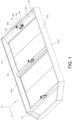
- a battery pack case 10 is provided.
- the battery pack case 10 includes a beam 20 disposed inside the battery pack case 10 (the beam 20 may also be disposed in a horizontal direction of the battery pack case 10 or disposed in a vertical direction of the battery pack case 10) and a connection column 30 connected to the beam 20.
- a first chamber 201 is disposed inside the beam 20 and extends in a length direction (i.e., an X direction and a Y direction of a horizontal plane of the battery pack case 10) of the beam 20, and the first chamber 201 penetrates through the beam 20.
- the connection column 30 penetrates through a side wall of the first chamber 201.
- the battery pack case 10 includes a bottom plate 101 and a frame 102 disposed on the bottom plate 101.
- the bottom plate 101 and the frame 102 forms a second chamber 103, and the second chamber 103 is configured to accommodate a battery.
- a Z axis is defined as a thickness direction of the battery pack case 10.
- One side of the battery pack case 10 close to a plane formed by an X axis and a Y axis is a bottom portion of the battery pack case 10, and one side of the battery pack case 10 away from the plane formed by the X axis and the Y axis is a top portion of the battery pack case 10.
- the blocking portions 40 may prevent an external liquid from entering an inner portion (i.e., the second chamber103) of the battery pack case 10 through the first chamber 201, airtightness of the battery pack case 10 is improved. Further, since the first chamber 201 is disposed inside the beam 20, a weight of the beam 20 is reduced, and a weight of the battery pack case 10 is also reduced.
- the battery pack case 10 acts as a core component of a battery electric vehicle. Since mass of the battery pack case 10 accounts for about one-third of a complete vehicle kerb mass, development of lightweight design of a structure of the battery pack case 10 is of great significance for improving a target range of the battery electric vehicle.
- connection column 30 penetrates through the bottom plate 101 of the battery pack case 10, so the battery pack case 10 may exhibit favorable firmness and stability.
- the connection column 30 is configured to connect the battery pack and the vehicle, such that the battery pack is secured in the vehicle through the connection column 30.
- an avoidance groove matched with a first end 301 of the connection column 30 is disposed on the bottom plate 101 to avoid the connection column 30, and in this way, the battery pack case 10 may exhibit favorable firmness and stability.
- the first end 301 of the connection column 30 penetrates through the beam 20 in a direction (i.e., the Z axis direction of the battery pack case 10) perpendicular to the length direction of the beam 20, and in this way, the battery pack case 10 may exhibit improved firmness and stability.
- a second end 302 of the connection column 30 is connected to a wall body 104 of one side on the battery pack case 10 away from the beam 20, and in this way, the battery pack case 10 may exhibit improved firmness and stability, and a favorable sealing property is also provided.
- a bottom portion of the beam 20 is attached to the bottom plate 101, so that firmness, stability and the sealing property of the battery pack case 10 may be further improved.
- a bottom surface of the beam 20 is attached to a top surface of the bottom plate 101.
- a side surface of a bottom portion 202 of the beam 20 is attached to a side surface of the bottom plate 101.
- the beam 20 is welded to the bottom plate 101.
- the beam 20 and the bottom plate 101 are an integral structure, which is simple and may be easily formed.
- the blocking portions 40 are respectively disposed on two ends of the beam 20, and the blocking portions 40 are connected to the frame 102 of the battery pack case 10.
- the blocking portions 40 are provided, and the two blocking portions 40 are respectively disposed on two ends of the beam 20.
- the frame 102 of the battery pack case 10 includes a first side wall 1021 and a second side wall 1022 opposite to each other. The two ends of the beam 20 are respectively connected to the first side wall 1021 and the second side wall 1022.
- the blocking portions 40 are provided as block bodies.
- a distance between the blocking portion 40 close to a first end of the beam 20 and the first end of the beam 20 is greater than or equal to 5 millimeters and less than or equal to 25 millimeters.
- a distance between the blocking portion 40 close to a second end of the beam 20 and the second end of the beam 20 is greater than or equal to 5 millimeters and less than or equal to 25 millimeters.
- the blocking portions 40 may be conveniently disposed in the first chamber 201 without affecting the connection between the frame 102 of the battery pack case 10 and the beam 20.
- the frame 102 of the battery pack case 10 is welded to the beam 20.
- the blocking portions 40 are provided as plate bodies. As structures of the blocking portions 40 are simple, the blocking portions 40 may be conveniently manufactured and shaped, and the plate-shaped blocking portions 40 may be conveniently disposed in the first chamber 201 without affecting the welding between the beam 20 and the frame 102 of the battery pack case 10.
- each of the blocking portions 40 and an inner wall of the beam 20 are welded through a welded seam portion 50. In this way, firmness and stability of the blocking portions 40 are improved, and the sealing effect of the battery pack case 10 is also enhanced.
- a first sealing portion 60 is disposed at a joint between the bottom portion 202 of the beam 20 and the connection column 30. In this way, firmness and stability of the connection column 30 are improved, and the sealing effect of the battery pack case 10 is also enhanced.
- a second sealing portion 70 is disposed at a joint between the top portion 203 of the beam 20 and the connection column 30. In this way, firmness and stability of the connection column 30 are further improved, and the sealing effect of the battery pack case 10 is also enhanced.
- the top portion 203 of the beam 20 and the bottom portion 202 of the beam 20 are opposite to each other. As an example, the bottom portion 202 of the beam 20 acts as an outer side of the beam 20. The top portion 203 of the beam 20 acts as an inner side of the beam 20.
- the first sealing portion 60 includes a first circumferential welded seam disposed on an outer surface of the joint between the bottom portion 202 of the beam 20 and the connection column 30, so that favorable welding strength and improved sealing effect are provided.
- the second sealing portion 70 includes a second circumferential welded seam disposed on an outer surface of the joint between the top portion 203 of the beam 20 and the connection column 30, so that favorable welding strength and improved sealing effect are provided.
- a reinforcing member is further included.
- the reinforcing member 80 is connected to the beam 20 and the connection column 30 through a first fastener 90, and through arrangement of the reinforcing member 80, the connection column 30 may be conveniently fixed, space saving is achieved, strength and rigidity of the connection column 30 are improved, and safety of use of the battery pack case 10 is enhanced.
- the first fastener 90 includes first bolts 901 and second bolts 902.
- a first reinforcing portion 801 of the reinforcing member 80 is connected to the connection column 30 through the first bolts 901.
- a second reinforcing portion 802 of the reinforcing member 80 is connected to the beam 20 through the second bolts 902.
- a side wall of the top portion 203 of the beam 20 is provided with a blind hole portion 100 configured for fixing the second bolt 902, and in this way, the sealing effect of the battery pack case 10 is further improved.
- the first reinforcing portion 801 of the reinforcing member 80 is a top side of the reinforcing member 80.
- the second reinforcing portion 802 of the reinforcing member 80 is a bottom side of the reinforcing member 80.
- the blind hole portion 100 is formed through riveting by a first sealing blind rivet nut 1001.
- the first sealing blind rivet nut 1001 includes a head portion and a penetration and installation portion connected to the head portion. A bottom portion of the penetration and installation portion is closed, and an inner portion of the penetration and installation portion is provided with a thread matched with the second bolt 902.
- the first sealing blind rivet nut 1001 is non-circular, which has anti-rotation property.
- the side wall of the top portion 203 of the beam 20 is provided with a first polygonal hole 1002, and the penetration and installation portion is disposed in the first polygonal hole 1002, such that the first sealing blind rivet nut 1001 is prevented from rotating on the side wall of the top portion 203 of the beam 20.
- a sealing layer is formed between the side wall of the top portion 203 of the beam 20 and the first sealing blind rivet nut 1001, and requirements for sealing are thereby satisfied.
- the first sealing blind rivet nut 1001 may be securely meshed with the side wall of the top portion 203 of the beam 20 to prevent rotation and facilitate firmness and reliability
- the second bolt 902 penetrates through a connection hole 8021 (as shown in FIG. 7 and FIG.
- the blind hole portion 100 is formed through riveting by a second sealing blind rivet nut and the second bolt 902.
- a through hole penetrating through two ends is disposed inside the second sealing blind rivet nut.
- the side wall of the top portion 203 of the beam 20 is provided with a second polygonal hole, and the second sealing blind rivet nut is placed in the second polygonal hole.
- a suitable tool may be adopted to secure the second bolt 902 penetrating through the connection hole 8021 (as shown in FIG. 7 and FIG. 8 ) of the second reinforcing portion 802 of the reinforcing member 80 and the second sealing blind rivet nut.
- a sleeve of the second sealing blind rivet nut is squeezed and deformed, and a bulging portion is pressed against an inner surface of the side wall of the top portion 203 of the beam 20.
- the second sealing blind rivet nut is fixed onto the side wall of the top portion 203 of the beam 20, and the second reinforcing portion 802 of the reinforcing member 80 and the beam 20 are thereby well connected and sealed.
- the blind hole portion 100 is formed through riveting by a third sealing blind rivet nut.
- a through hole penetrating through two ends is disposed inside the third sealing blind rivet nut.
- the side wall of the top portion 203 of the beam 20 is provided with a third polygonal hole.
- a suitable tool may be adopted to allow the third sealing blind rivet nut to be placed in the third polygonal hole and fixed onto the side wall of the top portion 203 of the beam 20.
- the second bolt 902 penetrates through the connection hole 8021 (as shown in FIG. 7 and FIG.
- connection column 30 is provided with a protruding portion 303.
- the protruding portion 303 is located on the joint between the connection column 30 and the top portion 203 of the beam 20 to facilitate connection between the reinforcing member 80 and the connection column 30.
- the first reinforcing portion 801 of the reinforcing member 80 is connected to the protruding portion 303 through the first bolts 901, and the reinforcing member 80 may be conveniently fixed through the protruding portion 303. Screw holes 3031 matched and used together with the first bolts 901 are disposed on the protruding portion 303.
- Each of the first bolts 901 penetrates through the connection hole 8011 of the first reinforcing portion 801 of the reinforcing member 80 to be matched and used together with the screw hole 3031, and in this way, the reinforcing member 80 and the connection column 30 may be easily and effectively fixed, and a simple structure which may be conveniently used is provided.
- the protruding portion 303 is disposed in a circumferential direction of the connection column 30, and in this way, strength of the connection column 30 is improved, and a favorable appearance is also provided.
- the protruding portion 303 may also be disposed only on one side of the connection column 30 close to the reinforcing member 80, such that the reinforcing member 80 may be conveniently connected.
- a shape of the protruding portion 303 may not be limited.
- the side wall of the top portion 203 of the beam 20 is provided with a groove portion 204 matched with the protruding portion 303 and configured for preventing the protruding portion 303 from rotating, such that the protruding portion 303 may be conveniently fixed.
- the connection column 30 may thus be positioned, and the reinforcing member 80 may thus be conveniently fixed through the first bolts 901.
- a cross section of the protruding portion 303 is non-circular, and correspondingly, a cross section of the groove portion 204 is non-circular.
- the connection column 30 cannot rotate.
- the connection column 30 may thus be positioned, and the reinforcing member 80 may be conveniently fixed through the first bolts 901.
- the protruding portion 303 is a flange.
- the flange is provided with a notch 3032, such that the flange may be conveniently connected and may withstand a great pressure.
- the flange is provided with the notch 3032, and correspondingly, the cross section of the groove portion 204 is non-circular, such that the groove portion 204 may be matched with the notch 3032 of the flange. In this way, when the flange is located in the groove portion 204, the connection column 30 cannot rotate, and the connection column 30 may thus be conveniently positioned.
- an inner surface of the second reinforcing portion 802 of the reinforcing member 80 is provided with a first avoidance portion 803 configured for the first sealing blind rivet nut 1001, the second sealing blind rivet nut, and/or the third sealing blind rivet nut to be avoided to facilitate connection between the reinforcing member 80 and the beam 20, and firmness is also improved.
- the inner surface of the second reinforcing portion 802 of the reinforcing member 80 is further provided with a second avoidance portion 804 configured for the second sealing portion 70 to be avoided to facilitate connection between the reinforcing member 80 and the connection column 30, and firmness is also improved.
- a number of the reinforcing member 80 is one or greater than one.
- a number of the first bolt 901 corresponding to each reinforcing member 80 is one or greater than one.
- a number of the second bolt 902 corresponding to each reinforcing member 80 is one or greater than one, and a number of the blind hole portion 100 is correspondingly be one or greater than one.
- the number of greater than one is at least two.
- the number of the reinforcing member 80 is two.
- the two reinforcing members 80 are symmetrically disposed on two sides of the connection column 30, so that a force is evenly received, and a good reinforcement effect is provided.
- the number of the first bolt 901 corresponding to each reinforcing member 80 is two.
- the number of the second bolt 902 corresponding to each reinforcing member 80 is two, and the number of the blind hole portion 100 is correspondingly be two.
- the reinforcing member 80 is formed by die casting of aluminum and mold processing and thereby exhibits a simple structure and may be conveniently used.
- connection column 30 and the wall body 104 are connected through the second fastener 110, and a portion of the second fastener 110 is inserted in the second end 302 of the connection column 30.
- the second fastener 110 is a third bolt, and a shank of the third bolt is inserted in the second end 302 of the connection column 30.
- the second end 302 of the connection column 30 is provided with a groove body 304.
- a sealing ring 120 (as shown in FIG. 2 ) configured for increasing airtightness between the connection column 30 and the wall body 104 is disposed inside the groove body 304, and a flange of the third bolt corresponds to the sealing ring 120, such that the sealing effect of the battery pack case 10 may be further improved.
- the groove body 304 may be disposed on one side of the wall body 104 facing the beam 20, and the sealing ring 120 is disposed in the groove body 304 and corresponds to the flange of the third bolt.
- the groove body 304 may also be disposed on one side of the wall body 104 facing a vehicle body, and the sealing ring 120 is disposed in the groove body 304 and corresponds to the flange of the third bolt.
- a third chamber 305 penetrating through the first end 301 and the second end of the connection column 30 is disposed inside the connection column 30.
- a cross section of the connection column 30 shaped as a circular ring. The shank of the third bolt is inserted in the third chamber 305 corresponding to the second end 302 of the connection column 30.
- an inverted T-shaped connector 130 is also included.
- a first end of the inverted T-shaped connector 130 penetrates through the third chamber 305 of the connection column 30, the wall body 104 and the third bolt, and is configured to connect the vehicle body and the battery pack case 10.
- a second end 1302 of the inverted T-shaped connector 130 is engaged with the first end 301 of the connection column 30, such that favorable firmness is achieved and a good sealing effect is provided.
- the inverted T-shaped connector 130 is a long bolt.
- the beam 20 when the beam 20 is connected to the battery pack case 10, the beam 20 is disposed on the bottom portion of the battery pack case 10.
- the beam 20 and the connection column 30 are both disposed on a tail portion of the battery pack case 10, and in this way, space saving is achieved, and strength and rigidity of the battery pack case 10 may be effectively improved.
- the beam 20 is formed by extrusion of an aluminum profile, such that the battery pack case 10 may have a less weight and may be easily formed.
- a fourth chamber 205 and a fifth chamber 206 extending in the length direction of the beam 10 are respectively disposed on two sides of the first chamber 201.
- the fourth chamber 205 is disposed on one side away from a module and is configured for placement of a low-voltage wiring. An assembly space of the low-voltage wiring may thus be simplified, and the battery pack case 10 may be organized in an orderly manner.
- the fifth chamber 206 is disposed on one side close to the module and is configured for placement of the module and fixing of the blind rivet nut, such that the battery pack case 10 may be further organized in an orderly manner.
- the external liquid includes water.
- the disclosure When the disclosure is applied, it is ensured that when the entire vehicle is in a vibration and impact condition, if the first sealing portion 60 (as shown in FIG. 2 ) located on the bottom portion 202 of the beam 20 is cracked and failed, under the joint protection provided by the connection column 30, the blocking portions 40, the second sealing portion 70 and the blind hole portion 100, the external liquid is prevented from entering the battery pack case 10 through the joint between the top portion 203 of the beam 20 and the connection column 30 and the joint between the end portion of the beam 20 and the frame 102 of the battery pack case 10. As such, the battery pack case 10 is ensured to provide double airtightness.
- the battery pack case provided by the disclosure exhibits a high level of strength and ingress protection (IP), enhanced safety of use, good reliability, and a favorable sealing property.
- IP ingress protection
- the disclosure further provides a battery pack including the battery pack case, which has a favorable sealing property, a high level of strength and IP, enhanced safety of use and good reliability.
- the disclosure further provides a vehicle including the battery pack case, and the vehicle is capable of improving power supply performance, safety performance and stability performance of the vehicle.
Landscapes
- Engineering & Computer Science (AREA)
- Chemical & Material Sciences (AREA)
- Chemical Kinetics & Catalysis (AREA)
- Electrochemistry (AREA)
- General Chemical & Material Sciences (AREA)
- Transportation (AREA)
- Mechanical Engineering (AREA)
- Sustainable Development (AREA)
- Sustainable Energy (AREA)
- Power Engineering (AREA)
- Life Sciences & Earth Sciences (AREA)
- Combustion & Propulsion (AREA)
- Aviation & Aerospace Engineering (AREA)
- Battery Mounting, Suspending (AREA)
Applications Claiming Priority (1)
| Application Number | Priority Date | Filing Date | Title |
|---|---|---|---|
| CN202110511775.5A CN113241493B (zh) | 2021-05-11 | 2021-05-11 | 电池包箱体及具有该箱体的电池包和具有该电池包的车辆 |
Publications (2)
| Publication Number | Publication Date |
|---|---|
| EP4089819A1 EP4089819A1 (en) | 2022-11-16 |
| EP4089819B1 true EP4089819B1 (en) | 2024-03-13 |
Family
ID=76942832
Family Applications (1)
| Application Number | Title | Priority Date | Filing Date |
|---|---|---|---|
| EP21185708.1A Active EP4089819B1 (en) | 2021-05-11 | 2021-07-15 | Battery pack case, battery pack including the same and vehicle including battery pack |
Country Status (3)
| Country | Link |
|---|---|
| US (1) | US11766926B2 (zh) |
| EP (1) | EP4089819B1 (zh) |
| CN (1) | CN113241493B (zh) |
Families Citing this family (3)
| Publication number | Priority date | Publication date | Assignee | Title |
|---|---|---|---|---|
| CN114148212A (zh) * | 2016-11-21 | 2022-03-08 | 上海电巴新能源科技有限公司 | 锁止装置及电动汽车 |
| WO2023092457A1 (zh) * | 2021-11-26 | 2023-06-01 | 宁德时代新能源科技股份有限公司 | 电池的箱体、电池、用电装置、制备电池的方法和装置 |
| CN217788618U (zh) * | 2021-12-07 | 2022-11-11 | 北京车和家汽车科技有限公司 | 电池包箱体、电池包及车辆 |
Family Cites Families (17)
| Publication number | Priority date | Publication date | Assignee | Title |
|---|---|---|---|---|
| CN206076324U (zh) | 2016-09-22 | 2017-04-05 | 广州汽车集团股份有限公司 | 车用电池包下壳体结构、电池包壳体及电池包 |
| CN206379395U (zh) | 2016-12-23 | 2017-08-04 | 北汽福田汽车股份有限公司 | 蓄电池箱体和车辆 |
| CN106627083B (zh) * | 2017-01-13 | 2023-09-05 | 上海蔚来汽车有限公司 | 快速加解锁套件 |
| CN207938676U (zh) * | 2018-02-09 | 2018-10-02 | 比亚迪股份有限公司 | 电池托盘及电池包 |
| CN209544452U (zh) * | 2019-03-15 | 2019-10-25 | 北京新能源汽车股份有限公司蓝谷动力系统分公司 | 电池箱体的吊点结构 |
| CN110217090A (zh) * | 2019-04-30 | 2019-09-10 | 江苏恒义汽配制造有限公司 | 一种电池箱下托盘总成及其加工方法 |
| CN112018286B (zh) | 2019-05-31 | 2021-11-12 | 比亚迪股份有限公司 | 电池包以及车辆 |
| WO2020259434A1 (zh) * | 2019-06-27 | 2020-12-30 | 宁德时代新能源科技股份有限公司 | 电池包及车辆 |
| CN110544755B (zh) * | 2019-08-15 | 2024-09-03 | 江苏大学 | 一种钢铝混合电池包的下壳体 |
| CN110611064B (zh) * | 2019-09-29 | 2024-09-03 | 江苏大学 | 一种铝合金电池包下壳体 |
| US11038236B2 (en) * | 2019-09-30 | 2021-06-15 | Ford Global Technologies, Llc | Electrified vehicle battery pack attachment and sealing strategies |
| CN210349941U (zh) * | 2019-10-12 | 2020-04-17 | 顺普汽车零部件(中国)有限公司 | 一种动力电池箱 |
| CN211320166U (zh) * | 2019-12-26 | 2020-08-21 | 东软睿驰汽车技术(沈阳)有限公司 | 一种电池包及其吊点组件 |
| CN212124831U (zh) * | 2020-04-24 | 2020-12-11 | 东软睿驰汽车技术(沈阳)有限公司 | 电池包吊点套筒组件、电池包及电动汽车 |
| CN212796511U (zh) * | 2020-05-08 | 2021-03-26 | 北京新能源汽车股份有限公司 | 用于电池箱的底板组件和车辆 |
| CN212571172U (zh) | 2020-07-10 | 2021-02-19 | 中航锂电(洛阳)有限公司 | 二次电池箱体 |
| CN112751131B (zh) | 2021-01-22 | 2024-04-19 | 上海兰钧新能源科技有限公司 | 一种新型电池箱结构、电池包和电动车辆 |
-
2021
- 2021-05-11 CN CN202110511775.5A patent/CN113241493B/zh active Active
- 2021-07-14 US US17/375,011 patent/US11766926B2/en active Active
- 2021-07-15 EP EP21185708.1A patent/EP4089819B1/en active Active
Also Published As
| Publication number | Publication date |
|---|---|
| US11766926B2 (en) | 2023-09-26 |
| CN113241493A (zh) | 2021-08-10 |
| EP4089819A1 (en) | 2022-11-16 |
| US20220363116A1 (en) | 2022-11-17 |
| CN113241493B (zh) | 2023-09-26 |
Similar Documents
| Publication | Publication Date | Title |
|---|---|---|
| EP4089819B1 (en) | Battery pack case, battery pack including the same and vehicle including battery pack | |
| EP3838720B1 (en) | Side sill structure for vehicle | |
| RU2674645C2 (ru) | Дверь для транспортного средства | |
| US7699285B2 (en) | Automotive mirror mounting system | |
| CN112441134B (zh) | 一种车辆门槛的安装方法及车辆门槛结构 | |
| CN111301301A (zh) | 物品固定装置及物品固定结构的组装方法 | |
| CN113602361A (zh) | 一种新能源汽车的集成式碳纤维后围总成 | |
| CN217374670U (zh) | 一种变厚度汽车顶盖后横梁结构 | |
| JP3888551B2 (ja) | 車両用ドアヒンジ装着構造 | |
| CN211223619U (zh) | 一种车辆b柱组件及车辆 | |
| JP4080949B2 (ja) | 車体のフレーム構造 | |
| CN211918340U (zh) | 后背门及车辆 | |
| CN112441143B (zh) | 车身骨架和具有其的车辆 | |
| US20210214020A1 (en) | Battery Storage Arrangement, Use of a Carrier, Method for Assembling a Battery Storage Arrangement, and Working Device | |
| CN220320043U (zh) | 一种连接机构、电池包箱体及动力电池 | |
| JP2001301462A (ja) | ブラケットレスドアビーム | |
| CN219584288U (zh) | 副车架的安装结构及车辆 | |
| CN215751866U (zh) | 电池包以及车辆 | |
| CN215904289U (zh) | 车门总成和车辆 | |
| CN215184373U (zh) | 电池包箱体的吊点结构及具有该结构的电池包箱体和车辆 | |
| EP3871953A1 (en) | Vehicle framework structure and vehicle | |
| CN213619303U (zh) | 电池壳体的安装结构及电动车辆 | |
| CN221708866U (zh) | 衬套连接组件及电池包箱体 | |
| CN220884009U (zh) | 车门及车辆 | |
| KR20240098379A (ko) | 배터리 케이스의 사이드 프레임 |
Legal Events
| Date | Code | Title | Description |
|---|---|---|---|
| PUAI | Public reference made under article 153(3) epc to a published international application that has entered the european phase |
Free format text: ORIGINAL CODE: 0009012 |
|
| STAA | Information on the status of an ep patent application or granted ep patent |
Free format text: STATUS: REQUEST FOR EXAMINATION WAS MADE |
|
| 17P | Request for examination filed |
Effective date: 20210715 |
|
| AK | Designated contracting states |
Kind code of ref document: A1 Designated state(s): AL AT BE BG CH CY CZ DE DK EE ES FI FR GB GR HR HU IE IS IT LI LT LU LV MC MK MT NL NO PL PT RO RS SE SI SK SM TR |
|
| STAA | Information on the status of an ep patent application or granted ep patent |
Free format text: STATUS: EXAMINATION IS IN PROGRESS |
|
| 17Q | First examination report despatched |
Effective date: 20230320 |
|
| GRAP | Despatch of communication of intention to grant a patent |
Free format text: ORIGINAL CODE: EPIDOSNIGR1 |
|
| STAA | Information on the status of an ep patent application or granted ep patent |
Free format text: STATUS: GRANT OF PATENT IS INTENDED |
|
| INTG | Intention to grant announced |
Effective date: 20231018 |
|
| GRAS | Grant fee paid |
Free format text: ORIGINAL CODE: EPIDOSNIGR3 |
|
| GRAA | (expected) grant |
Free format text: ORIGINAL CODE: 0009210 |
|
| STAA | Information on the status of an ep patent application or granted ep patent |
Free format text: STATUS: THE PATENT HAS BEEN GRANTED |
|
| AK | Designated contracting states |
Kind code of ref document: B1 Designated state(s): AL AT BE BG CH CY CZ DE DK EE ES FI FR GB GR HR HU IE IS IT LI LT LU LV MC MK MT NL NO PL PT RO RS SE SI SK SM TR |
|
| REG | Reference to a national code |
Ref country code: GB Ref legal event code: FG4D |
|
| REG | Reference to a national code |
Ref country code: CH Ref legal event code: EP |
|
| REG | Reference to a national code |
Ref country code: DE Ref legal event code: R096 Ref document number: 602021010302 Country of ref document: DE |
|
| REG | Reference to a national code |
Ref country code: IE Ref legal event code: FG4D |
|
| PG25 | Lapsed in a contracting state [announced via postgrant information from national office to epo] |
Ref country code: LT Free format text: LAPSE BECAUSE OF FAILURE TO SUBMIT A TRANSLATION OF THE DESCRIPTION OR TO PAY THE FEE WITHIN THE PRESCRIBED TIME-LIMIT Effective date: 20240313 |
|
| REG | Reference to a national code |
Ref country code: LT Ref legal event code: MG9D |
|
| PG25 | Lapsed in a contracting state [announced via postgrant information from national office to epo] |
Ref country code: GR Free format text: LAPSE BECAUSE OF FAILURE TO SUBMIT A TRANSLATION OF THE DESCRIPTION OR TO PAY THE FEE WITHIN THE PRESCRIBED TIME-LIMIT Effective date: 20240614 |
|
| REG | Reference to a national code |
Ref country code: NL Ref legal event code: MP Effective date: 20240313 |
|
| PG25 | Lapsed in a contracting state [announced via postgrant information from national office to epo] |
Ref country code: RS Free format text: LAPSE BECAUSE OF FAILURE TO SUBMIT A TRANSLATION OF THE DESCRIPTION OR TO PAY THE FEE WITHIN THE PRESCRIBED TIME-LIMIT Effective date: 20240613 Ref country code: HR Free format text: LAPSE BECAUSE OF FAILURE TO SUBMIT A TRANSLATION OF THE DESCRIPTION OR TO PAY THE FEE WITHIN THE PRESCRIBED TIME-LIMIT Effective date: 20240313 |
|
| PG25 | Lapsed in a contracting state [announced via postgrant information from national office to epo] |
Ref country code: ES Free format text: LAPSE BECAUSE OF FAILURE TO SUBMIT A TRANSLATION OF THE DESCRIPTION OR TO PAY THE FEE WITHIN THE PRESCRIBED TIME-LIMIT Effective date: 20240313 |
|
| PG25 | Lapsed in a contracting state [announced via postgrant information from national office to epo] |
Ref country code: RS Free format text: LAPSE BECAUSE OF FAILURE TO SUBMIT A TRANSLATION OF THE DESCRIPTION OR TO PAY THE FEE WITHIN THE PRESCRIBED TIME-LIMIT Effective date: 20240613 Ref country code: NO Free format text: LAPSE BECAUSE OF FAILURE TO SUBMIT A TRANSLATION OF THE DESCRIPTION OR TO PAY THE FEE WITHIN THE PRESCRIBED TIME-LIMIT Effective date: 20240613 Ref country code: LT Free format text: LAPSE BECAUSE OF FAILURE TO SUBMIT A TRANSLATION OF THE DESCRIPTION OR TO PAY THE FEE WITHIN THE PRESCRIBED TIME-LIMIT Effective date: 20240313 Ref country code: HR Free format text: LAPSE BECAUSE OF FAILURE TO SUBMIT A TRANSLATION OF THE DESCRIPTION OR TO PAY THE FEE WITHIN THE PRESCRIBED TIME-LIMIT Effective date: 20240313 Ref country code: GR Free format text: LAPSE BECAUSE OF FAILURE TO SUBMIT A TRANSLATION OF THE DESCRIPTION OR TO PAY THE FEE WITHIN THE PRESCRIBED TIME-LIMIT Effective date: 20240614 Ref country code: FI Free format text: LAPSE BECAUSE OF FAILURE TO SUBMIT A TRANSLATION OF THE DESCRIPTION OR TO PAY THE FEE WITHIN THE PRESCRIBED TIME-LIMIT Effective date: 20240313 Ref country code: ES Free format text: LAPSE BECAUSE OF FAILURE TO SUBMIT A TRANSLATION OF THE DESCRIPTION OR TO PAY THE FEE WITHIN THE PRESCRIBED TIME-LIMIT Effective date: 20240313 Ref country code: BG Free format text: LAPSE BECAUSE OF FAILURE TO SUBMIT A TRANSLATION OF THE DESCRIPTION OR TO PAY THE FEE WITHIN THE PRESCRIBED TIME-LIMIT Effective date: 20240313 |
|
| REG | Reference to a national code |
Ref country code: AT Ref legal event code: MK05 Ref document number: 1666629 Country of ref document: AT Kind code of ref document: T Effective date: 20240313 |
|
| PG25 | Lapsed in a contracting state [announced via postgrant information from national office to epo] |
Ref country code: SE Free format text: LAPSE BECAUSE OF FAILURE TO SUBMIT A TRANSLATION OF THE DESCRIPTION OR TO PAY THE FEE WITHIN THE PRESCRIBED TIME-LIMIT Effective date: 20240313 Ref country code: LV Free format text: LAPSE BECAUSE OF FAILURE TO SUBMIT A TRANSLATION OF THE DESCRIPTION OR TO PAY THE FEE WITHIN THE PRESCRIBED TIME-LIMIT Effective date: 20240313 |
|
| PG25 | Lapsed in a contracting state [announced via postgrant information from national office to epo] |
Ref country code: NL Free format text: LAPSE BECAUSE OF FAILURE TO SUBMIT A TRANSLATION OF THE DESCRIPTION OR TO PAY THE FEE WITHIN THE PRESCRIBED TIME-LIMIT Effective date: 20240313 |