EP4089291A1 - Halteelement - Google Patents
Halteelement Download PDFInfo
- Publication number
- EP4089291A1 EP4089291A1 EP22171953.7A EP22171953A EP4089291A1 EP 4089291 A1 EP4089291 A1 EP 4089291A1 EP 22171953 A EP22171953 A EP 22171953A EP 4089291 A1 EP4089291 A1 EP 4089291A1
- Authority
- EP
- European Patent Office
- Prior art keywords
- holding member
- projecting part
- projecting
- disposed
- grippers
- Prior art date
- Legal status (The legal status is an assumption and is not a legal conclusion. Google has not performed a legal analysis and makes no representation as to the accuracy of the status listed.)
- Withdrawn
Links
- 238000003780 insertion Methods 0.000 claims abstract description 20
- 230000037431 insertion Effects 0.000 claims abstract description 20
- 230000000149 penetrating effect Effects 0.000 claims abstract description 6
- WABPQHHGFIMREM-UHFFFAOYSA-N lead(0) Chemical compound [Pb] WABPQHHGFIMREM-UHFFFAOYSA-N 0.000 claims description 10
- 230000002093 peripheral effect Effects 0.000 claims description 2
- 239000011347 resin Substances 0.000 description 4
- 229920005989 resin Polymers 0.000 description 4
- 238000009434 installation Methods 0.000 description 2
- 238000012986 modification Methods 0.000 description 2
- 230000004048 modification Effects 0.000 description 2
- 238000000465 moulding Methods 0.000 description 2
- 238000005452 bending Methods 0.000 description 1
Images



Classifications
-
- F—MECHANICAL ENGINEERING; LIGHTING; HEATING; WEAPONS; BLASTING
- F16—ENGINEERING ELEMENTS AND UNITS; GENERAL MEASURES FOR PRODUCING AND MAINTAINING EFFECTIVE FUNCTIONING OF MACHINES OR INSTALLATIONS; THERMAL INSULATION IN GENERAL
- F16B—DEVICES FOR FASTENING OR SECURING CONSTRUCTIONAL ELEMENTS OR MACHINE PARTS TOGETHER, e.g. NAILS, BOLTS, CIRCLIPS, CLAMPS, CLIPS OR WEDGES; JOINTS OR JOINTING
- F16B5/00—Joining sheets or plates, e.g. panels, to one another or to strips or bars parallel to them
- F16B5/02—Joining sheets or plates, e.g. panels, to one another or to strips or bars parallel to them by means of fastening members using screw-thread
- F16B5/0241—Joining sheets or plates, e.g. panels, to one another or to strips or bars parallel to them by means of fastening members using screw-thread with the possibility for the connection to absorb deformation, e.g. thermal or vibrational
-
- H—ELECTRICITY
- H02—GENERATION; CONVERSION OR DISTRIBUTION OF ELECTRIC POWER
- H02K—DYNAMO-ELECTRIC MACHINES
- H02K5/00—Casings; Enclosures; Supports
- H02K5/24—Casings; Enclosures; Supports specially adapted for suppression or reduction of noise or vibrations
-
- F—MECHANICAL ENGINEERING; LIGHTING; HEATING; WEAPONS; BLASTING
- F04—POSITIVE - DISPLACEMENT MACHINES FOR LIQUIDS; PUMPS FOR LIQUIDS OR ELASTIC FLUIDS
- F04D—NON-POSITIVE-DISPLACEMENT PUMPS
- F04D29/00—Details, component parts, or accessories
- F04D29/66—Combating cavitation, whirls, noise, vibration or the like; Balancing
- F04D29/661—Combating cavitation, whirls, noise, vibration or the like; Balancing especially adapted for elastic fluid pumps
- F04D29/668—Combating cavitation, whirls, noise, vibration or the like; Balancing especially adapted for elastic fluid pumps damping or preventing mechanical vibrations
-
- H—ELECTRICITY
- H02—GENERATION; CONVERSION OR DISTRIBUTION OF ELECTRIC POWER
- H02K—DYNAMO-ELECTRIC MACHINES
- H02K5/00—Casings; Enclosures; Supports
- H02K5/04—Casings or enclosures characterised by the shape, form or construction thereof
Definitions
- the disclosure relates to a holding member that holds a motor.
- a conventional supported body includes a plate-shaped part having an open hole (through hole).
- a tubular elastic member is disposed inside the open hole. By inserting and screwing a boss into the elastic member, the supported body is fixed to a support. By disposing the elastic member, vibration occurring between the supported body and the support is able to be absorbed.
- An exemplary holding member of the disclosure is a holding member that holds a motor.
- the holding member includes a base and multiple attachment parts.
- the base has the motor disposed on an upper surface thereof with a center axis of rotation of the motor arranged in an up-down direction.
- the attachment part is disposed radially outside the base.
- the attachment part includes a frame, a pair of grippers, a first projecting part, and a second projecting part.
- the frame surrounds an insertion hole penetrating in an axial direction and is connected to the base.
- the pair of grippers is disposed inside the insertion hole and extends radially outward from the base.
- the first projecting part is disposed between the pair of grippers and projects radially outward from the base.
- the second projecting part projects from the frame into the insertion hole.
- axial direction a direction parallel to a central axis C of a motor 30, a direction orthogonal to the central axis C of the motor 30, and a direction along an arc centered on the central axis C of the motor 30
- axial direction a direction parallel to a central axis C of a motor 30, a direction orthogonal to the central axis C of the motor 30, and a direction along an arc centered on the central axis C of the motor 30
- axial direction directions that coincide with the axial direction, radial direction, and circumferential direction of the motor 30 in a state in which the motor 30 is disposed are simply referred to as "axial direction”, “diameter direction”, and “circumferential direction”, respectively.
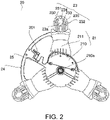
- FIG. 1 and FIG. 2 are respectively a side view and a top view of the holding member 20 according to an embodiment.
- FIG. 1 illustrates a state in which the motor 30 is installed on the holding member 20, and the motor 30 is simply illustrated in broken line.
- the holding member 20 includes a base 21, an attachment part 23, a connection part 24, and a lead wire holder 25, and is integrally molded with resin.
- the holding member 20 holds the motor 30.
- the motor 30 includes a rotation part 31 that rotates about the central axis C extending in the up-down direction.
- an impeller (not illustrated) is attached to the rotation part 31.
- the base 21 includes a plate 210 and an arm 211.
- the plate 210 is defined in a plate shape or a substantially plate shape, and has the motor 30 disposed on an upper surface thereof.
- the plate 210 is defined in a circular plate shape or a substantially circular plate shape orthogonal to the central axis C. In the center (on the central axis C) of the plate 210, a cylindrical part 210a extends axially upward.
- the motor 30 has an installation hole 32 that opens in a center of a lower surface, and the cylindrical part 210a is inserted into the installation hole 32. Accordingly, the motor 30 is installed on the base 21.
- the plate 210 is defined in a circular plate shape or a substantially circular plate shape, but may also be defined in a polygonal plate shape or a substantially polygonal plate shape.
- the arm 211 extends radially outward from a radially outer surface of the plate 210, and the attachment part 23 is disposed radially outside the arm 211.
- the arm 211 is defined in a plate shape or a substantially plate shape and is disposed in plural in the circumferential direction. In the present embodiment, the arm 211 is provided in three places at equal intervals in the circumferential direction. The arm 211 may be provided in two or four or more places at equal intervals in the circumferential direction.
- connection part 24 connects outer peripheral parts of adjacent arms 211 in the circumferential direction and is defined in an arc shape or a substantially arc shape. By providing the connection part 24, the strength of the arm 211 is able to be improved. In the present embodiment, the connection part 24 is provided in only one place. The connection part 24 may be provided in two or more places.
- the lead wire holder 25 extends in the radial direction from a circumferential center of the connection part 24 and bridges the connection part 24 and the plate 210.
- the lead wire holder 25 includes a hook 251 projecting in the circumferential direction.
- a lead wire (not illustrated) electrically connected to the motor 30 is hooked on the hook 251 and pulled radially outward of the holding member 20.
- the lead wire holder 25 is connected to the connection part 24, and the strength of the lead wire holder 25 is able to be improved. Accordingly, deformation of the lead wire holder 25 in the axial direction due to the weight of the lead wire is able to be suppressed.
- FIG. 3 and FIG. 4 are enlarged perspective views of the attachment part 23.
- FIG. 3 illustrates the attachment part 23 as viewed from an axially upper side
- FIG. 4 illustrates the attachment part 23 as viewed from an axially lower side
- FIG. 5 is an enlarged vertical sectional view of the attachment part 23, illustrating a state in which the attachment part 23 is screwed to the boss B.
- the attachment part 23 is disposed radially outside each arm 211 of the base 21, and an insertion hole 23a penetrating in the axial direction opens in the attachment part 23.
- Multiple attachment parts 23 each include a frame 231, a pair of grippers 232, a first projecting part 233, a second projecting part 234, and a third projecting part 235.
- the frame 231 surrounds the insertion hole 23a and is connected to the base 21.
- the frame 231 is defined in an arc shape or a substantially arc shape convex radially outward as viewed in the axial direction, and has both ends connected to radially outer ends of the arm 211.
- the insertion hole 23a is defined by being surrounded by the radially outer ends of the arm 211 and the frame 231.
- the frame 231 includes a frame convex part 231a.
- the frame convex part 231a projects into the insertion hole 23a.
- the pair of grippers 232 is disposed inside the insertion hole 23a and extends radially outward from the base 21. In the present embodiment, the gripper 232 extends radially outward from the radially outer end of the arm 211.
- the pair of grippers 232 are disposed side by side in the circumferential direction and extend substantially in parallel. A radially outer end of the gripper 232 faces the frame 231 in the radial direction via a gap therebetween.
- the gripper 232 is integrally molded with the arm 211 with resin, and bends in the circumferential direction.
- the gripper 232 includes a protrusion 232a, a gripping convex part 232b, and an inclined part 232c.
- the protrusion 232a is provided in plural on facing surfaces of the pair of grippers 232 that face each other at the radially outer ends of the grippers 232.
- the protrusion 232a extends in the axial direction, and three protrusions 232a are disposed side by side in the radial direction on each gripper 232. Accordingly, when the boss B having a tubular or substantially tubular shape is gripped by the pair of grippers 232, the protrusion 232a contacts the boss B.
- the pair of grippers 232 is able to stably grip the bosses B having different diameters while bending in the circumferential direction.
- Two or four or more protrusions 232a may be disposed side by side in the radial direction on the facing surfaces.
- a total of six protrusions 232a defined on the pair of grippers 232 are disposed in a circular or substantially circular shape as viewed in the axial direction. That is, envelopes of the six protrusion 232a are defined in a circular or substantially circular shape as viewed in the axial direction. Accordingly, the pair of grippers 232 is able to stably grip the boss B having a columnar or substantially columnar shape.
- the gripping convex part 232b projects in a direction away from the other gripper 232.
- the gripping convex part 232b and the frame convex part 231a face each other in the circumferential direction.
- the grippers 232 bend in directions away from each other.
- the gripping convex part 232b and the frame part 231a contact each other, and the gripper 232 is restricted from being greatly bent. Accordingly, damage to the gripper 232 is able to be prevented.
- Either the gripping convex part 232b or the frame convex part 231a may be omitted.
- the inclined part 232c is disposed at an axially lower end of the gripper 232, and is inclined in a direction approaching the other gripper 232 toward the axially upper side.
- the first projecting part 233 is disposed between the pair of grippers 232 and projects radially outward from the base 21.
- the first projecting part 233 projects radially outward from the radially outer end of the arm 211.
- the first projecting part 233 has a through hole 233a penetrating in the axial direction.
- the second projecting part 234 projects from the frame 231 into the insertion hole 23a.
- the first projecting part 233 and the second projecting part 234 face each other in the radial direction.
- the second projecting part 234 has a through hole 234a penetrating in the axial direction.
- the third projecting part 235 is disposed adjacent to the second projecting part 234 in the circumferential direction and projects from the frame 231 into the insertion hole 23a.
- the third projecting part 235 projects radially inward from an axially upper end of the frame 231.
- An upper surface of the frame 231, an upper surface of the second projecting part 234, and an upper surface of the third projecting part 235 are defined flush with each other.
- the upper surface of the third projecting part 235 is at the same axial height as the upper surfaces of the first projecting part 233 and the second projecting part 234 (see FIG. 5 ).
- the upper surface of the third projecting part 235 is preferably located at the same axial height as the axially higher one of the upper surface of the first projecting part 233 and the upper surface of the second projecting part 234.
- the upper surfaces of the first projecting part 233 and the second projecting part 234 are located on the axially upper side of the upper surface of the gripper 232.
- a lower surface of the attachment part 23 is located on the axially lower side of a lower surface of the base 21.
- a lower surface of the frame 231 is at the same axial height as a lower surface of the first projecting part 233 (see FIG. 5 ).
- the lower surface of the frame 231 and the lower surface of the first projecting part 233 are located on the axially lower side of a lower surface of the gripper 232, a lower surface of the second projecting part 234, and a lower surface of the third projecting part 235.
- the pair of grippers 232 grips the boss B projecting axially upward from the attachment surface 100.
- the boss B is able to be easily positioned inside the insertion hole 23a. Accordingly, assembly workability of the holding member 20 is improved.
- the attachment part 23 is screwed to the boss B by a screw S via a washer W.
- the washer W contacts the upper surface of the first projecting part 233, the upper surface of the frame 231, the upper surface of the second projecting part 234, and the upper surface of the third projecting part 235. Accordingly, the vibration of the motor 30 in the axial direction is absorbed by the first projecting part 233, the second projecting part 234 and the third projecting part 235.
- the holding member 20 is able to be provided that is able to absorb the vibration of the motor 30 and is easily attached to an actual machine, while an elastic member such as rubber is omitted and the number of parts is reduced.
- the first projecting part 233 and the second projecting part 234 face each other in the radial direction, and the washer W is stably supported by the first projecting part 233 and the second projecting part 234. Accordingly, the vibration of the motor 30 is able to be further absorbed.
- the upper surfaces of the first projecting part 233 and the second projecting part 234 are located on the axially upper side of the upper surface of the gripper 232, and the washer W is not in contact with the upper surface of the gripper 232. Accordingly, the gripper 232 is prevented from being damaged by the vibration of the motor 30.
- the gripper 232 is able to be molded to be thinned in the axial direction and easily bent in the circumferential direction. Accordingly, the boss B is able to be inserted between the pair of grippers 232 according to the outer diameter of the boss B, and the device body and the holding member 20 are able to be easily positioned. Accordingly, assembly workability of the holding member 20 is further improved.
- the disclosure is able to be applied in, for example, a blower mounted on a household electric appliance such as a refrigerator.
Landscapes
- Engineering & Computer Science (AREA)
- Power Engineering (AREA)
- General Engineering & Computer Science (AREA)
- Mechanical Engineering (AREA)
- Motor Or Generator Frames (AREA)
- Vibration Prevention Devices (AREA)
Applications Claiming Priority (1)
| Application Number | Priority Date | Filing Date | Title |
|---|---|---|---|
| JP2021081043A JP2022174964A (ja) | 2021-05-12 | 2021-05-12 | 保持部材 |
Publications (1)
| Publication Number | Publication Date |
|---|---|
| EP4089291A1 true EP4089291A1 (de) | 2022-11-16 |
Family
ID=82019793
Family Applications (1)
| Application Number | Title | Priority Date | Filing Date |
|---|---|---|---|
| EP22171953.7A Withdrawn EP4089291A1 (de) | 2021-05-12 | 2022-05-06 | Halteelement |
Country Status (4)
| Country | Link |
|---|---|
| US (1) | US20220368193A1 (de) |
| EP (1) | EP4089291A1 (de) |
| JP (1) | JP2022174964A (de) |
| CN (1) | CN115347724A (de) |
Citations (4)
| Publication number | Priority date | Publication date | Assignee | Title |
|---|---|---|---|---|
| US20080273980A1 (en) * | 2007-02-28 | 2008-11-06 | Snecma | Turbomachine fan |
| CN206222805U (zh) * | 2016-11-14 | 2017-06-06 | 青岛海尔股份有限公司 | 用于冰箱中风机安装的减震垫及冰箱 |
| US20200240438A1 (en) * | 2019-01-30 | 2020-07-30 | Nidec Corporation | Fan |
| US20210108694A1 (en) * | 2017-04-18 | 2021-04-15 | Bsh Hausgeraete Gmbh | Refrigeration device comprising a damping disc |
Family Cites Families (7)
| Publication number | Priority date | Publication date | Assignee | Title |
|---|---|---|---|---|
| DE102013226563B4 (de) * | 2013-12-19 | 2017-03-09 | Eberspächer Climate Control Systems GmbH & Co. KG | Gebläsegehäuse, insbesondere für ein Seitenkanalgebläse |
| JP2019030141A (ja) * | 2017-07-31 | 2019-02-21 | 日本電産テクノモータ株式会社 | コネクタ及びコネクタを備えたモータ |
| JP7031441B2 (ja) * | 2017-09-28 | 2022-03-08 | 日本電産株式会社 | モータ |
| KR102016227B1 (ko) * | 2017-11-28 | 2019-08-29 | 엘지전자 주식회사 | 팬 조립체 및 이를 포함하는 냉장고 |
| JP2019180200A (ja) * | 2018-03-30 | 2019-10-17 | 日本電産株式会社 | モータ及び送風装置 |
| JP2020005460A (ja) * | 2018-06-29 | 2020-01-09 | 日本電産株式会社 | モータ |
| JP2020124046A (ja) * | 2019-01-30 | 2020-08-13 | 日本電産トーソク株式会社 | 電動アクチュエータ |
-
2021
- 2021-05-12 JP JP2021081043A patent/JP2022174964A/ja active Pending
-
2022
- 2022-05-06 CN CN202210484242.7A patent/CN115347724A/zh not_active Withdrawn
- 2022-05-06 EP EP22171953.7A patent/EP4089291A1/de not_active Withdrawn
- 2022-05-10 US US17/740,370 patent/US20220368193A1/en not_active Abandoned
Patent Citations (4)
| Publication number | Priority date | Publication date | Assignee | Title |
|---|---|---|---|---|
| US20080273980A1 (en) * | 2007-02-28 | 2008-11-06 | Snecma | Turbomachine fan |
| CN206222805U (zh) * | 2016-11-14 | 2017-06-06 | 青岛海尔股份有限公司 | 用于冰箱中风机安装的减震垫及冰箱 |
| US20210108694A1 (en) * | 2017-04-18 | 2021-04-15 | Bsh Hausgeraete Gmbh | Refrigeration device comprising a damping disc |
| US20200240438A1 (en) * | 2019-01-30 | 2020-07-30 | Nidec Corporation | Fan |
Also Published As
| Publication number | Publication date |
|---|---|
| US20220368193A1 (en) | 2022-11-17 |
| CN115347724A (zh) | 2022-11-15 |
| JP2022174964A (ja) | 2022-11-25 |
Similar Documents
| Publication | Publication Date | Title |
|---|---|---|
| US10862363B2 (en) | Motor | |
| EP3299506B1 (de) | Verstärkung einer kappe für eine wannenrückwand eines geräts | |
| EP4089291A1 (de) | Halteelement | |
| US20190305656A1 (en) | Motor | |
| WO2018062446A1 (ja) | モータ | |
| CN109586515B (zh) | 马达和传感器安装构造 | |
| JP2022127367A (ja) | モータ | |
| JP5057204B2 (ja) | 電動機 | |
| US20210226501A1 (en) | Motor | |
| EP2830197A1 (de) | Stützvorrichtung eines bürstenhalters und motor | |
| CN111052561A (zh) | 马达 | |
| JP2010263765A (ja) | 回転電機における固定子 | |
| US20210351657A1 (en) | Motor | |
| US11038395B2 (en) | Rotor of rotary electrical machine | |
| KR102836087B1 (ko) | 모터 | |
| JP6070467B2 (ja) | グロメット及びグロメット付ワイヤーハーネス | |
| JP4900780B2 (ja) | 電動機 | |
| CN211209515U (zh) | 马达和电气产品 | |
| CN224154046U (zh) | 电机及应用该电机的家用电器、电动工具 | |
| CN110224536B (zh) | 电机 | |
| CN219499054U (zh) | 一种电机安装支架 | |
| KR20220091198A (ko) | 모터 | |
| CN206250860U (zh) | 马达 | |
| CN214478004U (zh) | 短接环组件、电机和送风装置 | |
| US20250012313A1 (en) | Fastener and Fastener Assembly |
Legal Events
| Date | Code | Title | Description |
|---|---|---|---|
| PUAI | Public reference made under article 153(3) epc to a published international application that has entered the european phase |
Free format text: ORIGINAL CODE: 0009012 |
|
| STAA | Information on the status of an ep patent application or granted ep patent |
Free format text: STATUS: REQUEST FOR EXAMINATION WAS MADE |
|
| 17P | Request for examination filed |
Effective date: 20220506 |
|
| AK | Designated contracting states |
Kind code of ref document: A1 Designated state(s): AL AT BE BG CH CY CZ DE DK EE ES FI FR GB GR HR HU IE IS IT LI LT LU LV MC MK MT NL NO PL PT RO RS SE SI SK SM TR |
|
| RBV | Designated contracting states (corrected) |
Designated state(s): AL AT BE BG CH CY CZ DE DK EE ES FI FR GB GR HR HU IE IS IT LI LT LU LV MC MK MT NL NO PL PT RO RS SE SI SK SM TR |
|
| STAA | Information on the status of an ep patent application or granted ep patent |
Free format text: STATUS: EXAMINATION IS IN PROGRESS |
|
| 17Q | First examination report despatched |
Effective date: 20240315 |
|
| STAA | Information on the status of an ep patent application or granted ep patent |
Free format text: STATUS: THE APPLICATION HAS BEEN WITHDRAWN |
|
| 18W | Application withdrawn |
Effective date: 20240703 |