EP4089266B1 - Abgasreinigungssystem und verfahren zur reinigung von abgas und verwendung des abgasreinigungssystems - Google Patents
Abgasreinigungssystem und verfahren zur reinigung von abgas und verwendung des abgasreinigungssystems Download PDFInfo
- Publication number
- EP4089266B1 EP4089266B1 EP21173594.9A EP21173594A EP4089266B1 EP 4089266 B1 EP4089266 B1 EP 4089266B1 EP 21173594 A EP21173594 A EP 21173594A EP 4089266 B1 EP4089266 B1 EP 4089266B1
- Authority
- EP
- European Patent Office
- Prior art keywords
- exhaust gas
- filter rods
- perforated plate
- casing
- cleaning system
- Prior art date
- Legal status (The legal status is an assumption and is not a legal conclusion. Google has not performed a legal analysis and makes no representation as to the accuracy of the status listed.)
- Active
Links
Images


Classifications
-
- F—MECHANICAL ENGINEERING; LIGHTING; HEATING; WEAPONS; BLASTING
- F01—MACHINES OR ENGINES IN GENERAL; ENGINE PLANTS IN GENERAL; STEAM ENGINES
- F01N—GAS-FLOW SILENCERS OR EXHAUST APPARATUS FOR MACHINES OR ENGINES IN GENERAL; GAS-FLOW SILENCERS OR EXHAUST APPARATUS FOR INTERNAL-COMBUSTION ENGINES
- F01N3/00—Exhaust or silencing apparatus having means for purifying, rendering innocuous, or otherwise treating exhaust
- F01N3/02—Exhaust or silencing apparatus having means for purifying, rendering innocuous, or otherwise treating exhaust for cooling, or for removing solid constituents of, exhaust
- F01N3/021—Exhaust or silencing apparatus having means for purifying, rendering innocuous, or otherwise treating exhaust for cooling, or for removing solid constituents of, exhaust by means of filters
-
- F—MECHANICAL ENGINEERING; LIGHTING; HEATING; WEAPONS; BLASTING
- F01—MACHINES OR ENGINES IN GENERAL; ENGINE PLANTS IN GENERAL; STEAM ENGINES
- F01N—GAS-FLOW SILENCERS OR EXHAUST APPARATUS FOR MACHINES OR ENGINES IN GENERAL; GAS-FLOW SILENCERS OR EXHAUST APPARATUS FOR INTERNAL-COMBUSTION ENGINES
- F01N13/00—Exhaust or silencing apparatus characterised by constructional features
- F01N13/004—Exhaust or silencing apparatus characterised by constructional features specially adapted for marine propulsion, i.e. for receiving simultaneously engine exhaust gases and engine cooling water
-
- F—MECHANICAL ENGINEERING; LIGHTING; HEATING; WEAPONS; BLASTING
- F01—MACHINES OR ENGINES IN GENERAL; ENGINE PLANTS IN GENERAL; STEAM ENGINES
- F01N—GAS-FLOW SILENCERS OR EXHAUST APPARATUS FOR MACHINES OR ENGINES IN GENERAL; GAS-FLOW SILENCERS OR EXHAUST APPARATUS FOR INTERNAL-COMBUSTION ENGINES
- F01N13/00—Exhaust or silencing apparatus characterised by constructional features
- F01N13/009—Exhaust or silencing apparatus characterised by constructional features having two or more separate purifying devices arranged in series
- F01N13/0097—Exhaust or silencing apparatus characterised by constructional features having two or more separate purifying devices arranged in series the purifying devices are arranged in a single housing
-
- F—MECHANICAL ENGINEERING; LIGHTING; HEATING; WEAPONS; BLASTING
- F01—MACHINES OR ENGINES IN GENERAL; ENGINE PLANTS IN GENERAL; STEAM ENGINES
- F01N—GAS-FLOW SILENCERS OR EXHAUST APPARATUS FOR MACHINES OR ENGINES IN GENERAL; GAS-FLOW SILENCERS OR EXHAUST APPARATUS FOR INTERNAL-COMBUSTION ENGINES
- F01N13/00—Exhaust or silencing apparatus characterised by constructional features
- F01N13/02—Exhaust or silencing apparatus characterised by constructional features having two or more separate silencers in series
-
- F—MECHANICAL ENGINEERING; LIGHTING; HEATING; WEAPONS; BLASTING
- F01—MACHINES OR ENGINES IN GENERAL; ENGINE PLANTS IN GENERAL; STEAM ENGINES
- F01N—GAS-FLOW SILENCERS OR EXHAUST APPARATUS FOR MACHINES OR ENGINES IN GENERAL; GAS-FLOW SILENCERS OR EXHAUST APPARATUS FOR INTERNAL-COMBUSTION ENGINES
- F01N13/00—Exhaust or silencing apparatus characterised by constructional features
- F01N13/08—Other arrangements or adaptations of exhaust conduits
-
- F—MECHANICAL ENGINEERING; LIGHTING; HEATING; WEAPONS; BLASTING
- F01—MACHINES OR ENGINES IN GENERAL; ENGINE PLANTS IN GENERAL; STEAM ENGINES
- F01N—GAS-FLOW SILENCERS OR EXHAUST APPARATUS FOR MACHINES OR ENGINES IN GENERAL; GAS-FLOW SILENCERS OR EXHAUST APPARATUS FOR INTERNAL-COMBUSTION ENGINES
- F01N3/00—Exhaust or silencing apparatus having means for purifying, rendering innocuous, or otherwise treating exhaust
- F01N3/02—Exhaust or silencing apparatus having means for purifying, rendering innocuous, or otherwise treating exhaust for cooling, or for removing solid constituents of, exhaust
- F01N3/021—Exhaust or silencing apparatus having means for purifying, rendering innocuous, or otherwise treating exhaust for cooling, or for removing solid constituents of, exhaust by means of filters
- F01N3/0211—Arrangements for mounting filtering elements in housing, e.g. with means for compensating thermal expansion or vibration
-
- F—MECHANICAL ENGINEERING; LIGHTING; HEATING; WEAPONS; BLASTING
- F01—MACHINES OR ENGINES IN GENERAL; ENGINE PLANTS IN GENERAL; STEAM ENGINES
- F01N—GAS-FLOW SILENCERS OR EXHAUST APPARATUS FOR MACHINES OR ENGINES IN GENERAL; GAS-FLOW SILENCERS OR EXHAUST APPARATUS FOR INTERNAL-COMBUSTION ENGINES
- F01N3/00—Exhaust or silencing apparatus having means for purifying, rendering innocuous, or otherwise treating exhaust
- F01N3/02—Exhaust or silencing apparatus having means for purifying, rendering innocuous, or otherwise treating exhaust for cooling, or for removing solid constituents of, exhaust
- F01N3/021—Exhaust or silencing apparatus having means for purifying, rendering innocuous, or otherwise treating exhaust for cooling, or for removing solid constituents of, exhaust by means of filters
- F01N3/0212—Exhaust or silencing apparatus having means for purifying, rendering innocuous, or otherwise treating exhaust for cooling, or for removing solid constituents of, exhaust by means of filters with one or more perforated tubes surrounded by filtering material, e.g. filter candles
-
- F—MECHANICAL ENGINEERING; LIGHTING; HEATING; WEAPONS; BLASTING
- F01—MACHINES OR ENGINES IN GENERAL; ENGINE PLANTS IN GENERAL; STEAM ENGINES
- F01N—GAS-FLOW SILENCERS OR EXHAUST APPARATUS FOR MACHINES OR ENGINES IN GENERAL; GAS-FLOW SILENCERS OR EXHAUST APPARATUS FOR INTERNAL-COMBUSTION ENGINES
- F01N3/00—Exhaust or silencing apparatus having means for purifying, rendering innocuous, or otherwise treating exhaust
- F01N3/02—Exhaust or silencing apparatus having means for purifying, rendering innocuous, or otherwise treating exhaust for cooling, or for removing solid constituents of, exhaust
- F01N3/021—Exhaust or silencing apparatus having means for purifying, rendering innocuous, or otherwise treating exhaust for cooling, or for removing solid constituents of, exhaust by means of filters
- F01N3/022—Exhaust or silencing apparatus having means for purifying, rendering innocuous, or otherwise treating exhaust for cooling, or for removing solid constituents of, exhaust by means of filters characterised by specially adapted filtering structure, e.g. honeycomb, mesh or fibrous
-
- F—MECHANICAL ENGINEERING; LIGHTING; HEATING; WEAPONS; BLASTING
- F01—MACHINES OR ENGINES IN GENERAL; ENGINE PLANTS IN GENERAL; STEAM ENGINES
- F01N—GAS-FLOW SILENCERS OR EXHAUST APPARATUS FOR MACHINES OR ENGINES IN GENERAL; GAS-FLOW SILENCERS OR EXHAUST APPARATUS FOR INTERNAL-COMBUSTION ENGINES
- F01N3/00—Exhaust or silencing apparatus having means for purifying, rendering innocuous, or otherwise treating exhaust
- F01N3/02—Exhaust or silencing apparatus having means for purifying, rendering innocuous, or otherwise treating exhaust for cooling, or for removing solid constituents of, exhaust
- F01N3/021—Exhaust or silencing apparatus having means for purifying, rendering innocuous, or otherwise treating exhaust for cooling, or for removing solid constituents of, exhaust by means of filters
- F01N3/023—Exhaust or silencing apparatus having means for purifying, rendering innocuous, or otherwise treating exhaust for cooling, or for removing solid constituents of, exhaust by means of filters using means for regenerating the filters, e.g. by burning trapped particles
- F01N3/0233—Exhaust or silencing apparatus having means for purifying, rendering innocuous, or otherwise treating exhaust for cooling, or for removing solid constituents of, exhaust by means of filters using means for regenerating the filters, e.g. by burning trapped particles periodically cleaning filter by blowing a gas through the filter in a direction opposite to exhaust flow, e.g. exposing filter to engine air intake
-
- F—MECHANICAL ENGINEERING; LIGHTING; HEATING; WEAPONS; BLASTING
- F01—MACHINES OR ENGINES IN GENERAL; ENGINE PLANTS IN GENERAL; STEAM ENGINES
- F01N—GAS-FLOW SILENCERS OR EXHAUST APPARATUS FOR MACHINES OR ENGINES IN GENERAL; GAS-FLOW SILENCERS OR EXHAUST APPARATUS FOR INTERNAL-COMBUSTION ENGINES
- F01N3/00—Exhaust or silencing apparatus having means for purifying, rendering innocuous, or otherwise treating exhaust
- F01N3/02—Exhaust or silencing apparatus having means for purifying, rendering innocuous, or otherwise treating exhaust for cooling, or for removing solid constituents of, exhaust
- F01N3/021—Exhaust or silencing apparatus having means for purifying, rendering innocuous, or otherwise treating exhaust for cooling, or for removing solid constituents of, exhaust by means of filters
- F01N3/023—Exhaust or silencing apparatus having means for purifying, rendering innocuous, or otherwise treating exhaust for cooling, or for removing solid constituents of, exhaust by means of filters using means for regenerating the filters, e.g. by burning trapped particles
- F01N3/029—Exhaust or silencing apparatus having means for purifying, rendering innocuous, or otherwise treating exhaust for cooling, or for removing solid constituents of, exhaust by means of filters using means for regenerating the filters, e.g. by burning trapped particles by adding non-fuel substances to exhaust
-
- F—MECHANICAL ENGINEERING; LIGHTING; HEATING; WEAPONS; BLASTING
- F01—MACHINES OR ENGINES IN GENERAL; ENGINE PLANTS IN GENERAL; STEAM ENGINES
- F01N—GAS-FLOW SILENCERS OR EXHAUST APPARATUS FOR MACHINES OR ENGINES IN GENERAL; GAS-FLOW SILENCERS OR EXHAUST APPARATUS FOR INTERNAL-COMBUSTION ENGINES
- F01N3/00—Exhaust or silencing apparatus having means for purifying, rendering innocuous, or otherwise treating exhaust
- F01N3/02—Exhaust or silencing apparatus having means for purifying, rendering innocuous, or otherwise treating exhaust for cooling, or for removing solid constituents of, exhaust
- F01N3/021—Exhaust or silencing apparatus having means for purifying, rendering innocuous, or otherwise treating exhaust for cooling, or for removing solid constituents of, exhaust by means of filters
- F01N3/033—Exhaust or silencing apparatus having means for purifying, rendering innocuous, or otherwise treating exhaust for cooling, or for removing solid constituents of, exhaust by means of filters in combination with other devices
- F01N3/035—Exhaust or silencing apparatus having means for purifying, rendering innocuous, or otherwise treating exhaust for cooling, or for removing solid constituents of, exhaust by means of filters in combination with other devices with catalytic reactors
-
- F—MECHANICAL ENGINEERING; LIGHTING; HEATING; WEAPONS; BLASTING
- F01—MACHINES OR ENGINES IN GENERAL; ENGINE PLANTS IN GENERAL; STEAM ENGINES
- F01N—GAS-FLOW SILENCERS OR EXHAUST APPARATUS FOR MACHINES OR ENGINES IN GENERAL; GAS-FLOW SILENCERS OR EXHAUST APPARATUS FOR INTERNAL-COMBUSTION ENGINES
- F01N3/00—Exhaust or silencing apparatus having means for purifying, rendering innocuous, or otherwise treating exhaust
- F01N3/08—Exhaust or silencing apparatus having means for purifying, rendering innocuous, or otherwise treating exhaust for rendering innocuous
- F01N3/10—Exhaust or silencing apparatus having means for purifying, rendering innocuous, or otherwise treating exhaust for rendering innocuous by thermal or catalytic conversion of noxious components of exhaust
- F01N3/24—Exhaust or silencing apparatus having means for purifying, rendering innocuous, or otherwise treating exhaust for rendering innocuous by thermal or catalytic conversion of noxious components of exhaust characterised by constructional aspects of converting apparatus
- F01N3/28—Construction of catalytic reactors
- F01N3/2892—Exhaust flow directors or the like, e.g. upstream of catalytic device
-
- F—MECHANICAL ENGINEERING; LIGHTING; HEATING; WEAPONS; BLASTING
- F01—MACHINES OR ENGINES IN GENERAL; ENGINE PLANTS IN GENERAL; STEAM ENGINES
- F01N—GAS-FLOW SILENCERS OR EXHAUST APPARATUS FOR MACHINES OR ENGINES IN GENERAL; GAS-FLOW SILENCERS OR EXHAUST APPARATUS FOR INTERNAL-COMBUSTION ENGINES
- F01N2240/00—Combination or association of two or more different exhaust treating devices, or of at least one such device with an auxiliary device, not covered by indexing codes F01N2230/00 or F01N2250/00, one of the devices being
- F01N2240/20—Combination or association of two or more different exhaust treating devices, or of at least one such device with an auxiliary device, not covered by indexing codes F01N2230/00 or F01N2250/00, one of the devices being a flow director or deflector
-
- F—MECHANICAL ENGINEERING; LIGHTING; HEATING; WEAPONS; BLASTING
- F01—MACHINES OR ENGINES IN GENERAL; ENGINE PLANTS IN GENERAL; STEAM ENGINES
- F01N—GAS-FLOW SILENCERS OR EXHAUST APPARATUS FOR MACHINES OR ENGINES IN GENERAL; GAS-FLOW SILENCERS OR EXHAUST APPARATUS FOR INTERNAL-COMBUSTION ENGINES
- F01N2250/00—Combinations of different methods of purification
- F01N2250/02—Combinations of different methods of purification filtering and catalytic conversion
-
- F—MECHANICAL ENGINEERING; LIGHTING; HEATING; WEAPONS; BLASTING
- F01—MACHINES OR ENGINES IN GENERAL; ENGINE PLANTS IN GENERAL; STEAM ENGINES
- F01N—GAS-FLOW SILENCERS OR EXHAUST APPARATUS FOR MACHINES OR ENGINES IN GENERAL; GAS-FLOW SILENCERS OR EXHAUST APPARATUS FOR INTERNAL-COMBUSTION ENGINES
- F01N2260/00—Exhaust treating devices having provisions not otherwise provided for
- F01N2260/04—Exhaust treating devices having provisions not otherwise provided for for regeneration or reactivation, e.g. of catalyst
-
- F—MECHANICAL ENGINEERING; LIGHTING; HEATING; WEAPONS; BLASTING
- F01—MACHINES OR ENGINES IN GENERAL; ENGINE PLANTS IN GENERAL; STEAM ENGINES
- F01N—GAS-FLOW SILENCERS OR EXHAUST APPARATUS FOR MACHINES OR ENGINES IN GENERAL; GAS-FLOW SILENCERS OR EXHAUST APPARATUS FOR INTERNAL-COMBUSTION ENGINES
- F01N2330/00—Structure of catalyst support or particle filter
- F01N2330/06—Ceramic, e.g. monoliths
-
- F—MECHANICAL ENGINEERING; LIGHTING; HEATING; WEAPONS; BLASTING
- F01—MACHINES OR ENGINES IN GENERAL; ENGINE PLANTS IN GENERAL; STEAM ENGINES
- F01N—GAS-FLOW SILENCERS OR EXHAUST APPARATUS FOR MACHINES OR ENGINES IN GENERAL; GAS-FLOW SILENCERS OR EXHAUST APPARATUS FOR INTERNAL-COMBUSTION ENGINES
- F01N2470/00—Structure or shape of exhaust gas passages, pipes or tubes
- F01N2470/02—Tubes being perforated
-
- F—MECHANICAL ENGINEERING; LIGHTING; HEATING; WEAPONS; BLASTING
- F01—MACHINES OR ENGINES IN GENERAL; ENGINE PLANTS IN GENERAL; STEAM ENGINES
- F01N—GAS-FLOW SILENCERS OR EXHAUST APPARATUS FOR MACHINES OR ENGINES IN GENERAL; GAS-FLOW SILENCERS OR EXHAUST APPARATUS FOR INTERNAL-COMBUSTION ENGINES
- F01N2590/00—Exhaust or silencing apparatus adapted to particular use, e.g. for military applications, airplanes, submarines
- F01N2590/02—Exhaust or silencing apparatus adapted to particular use, e.g. for military applications, airplanes, submarines for marine vessels or naval applications
-
- Y—GENERAL TAGGING OF NEW TECHNOLOGICAL DEVELOPMENTS; GENERAL TAGGING OF CROSS-SECTIONAL TECHNOLOGIES SPANNING OVER SEVERAL SECTIONS OF THE IPC; TECHNICAL SUBJECTS COVERED BY FORMER USPC CROSS-REFERENCE ART COLLECTIONS [XRACs] AND DIGESTS
- Y02—TECHNOLOGIES OR APPLICATIONS FOR MITIGATION OR ADAPTATION AGAINST CLIMATE CHANGE
- Y02A—TECHNOLOGIES FOR ADAPTATION TO CLIMATE CHANGE
- Y02A50/00—TECHNOLOGIES FOR ADAPTATION TO CLIMATE CHANGE in human health protection, e.g. against extreme weather
- Y02A50/20—Air quality improvement or preservation, e.g. vehicle emission control or emission reduction by using catalytic converters
Definitions
- Exhaust gas of different kinds is generated in a myriad of different situations, for example in connection with propulsion of vessels.
- Large ships are typically driven by engines operating on sulphur containing fuel, more particularly high sulphur heavy fuel oil, or low sulphur fuel like VLSFO, ULSFO or diesel.
- exhaust gas containing nitrogen oxides (NO X ), and possibly sulphur oxides (SO X ) depending on the fuel sulphur level, is formed.
- the exhaust gas typically also contains particulate matter, such as soot, oil, heavy metals and black carbon (BC) primarily consisting of sub-micron elemental carbon particulates.
- the exhaust gas should be cleaned from these pollutants before it is released into the atmosphere.
- the exhaust gas could be passed through a wet scrubber for removal of sulphur oxides and particulate matter, and/or treated in a SCR reactor for removal of nitrogen oxides.
- the scrubber could be a so-called open loop scrubber, which uses the natural alkalinity of seawater to wash out the sulphur oxides from the exhaust gas. Seawater is then fed from the sea, through the scrubber for absorption of SO X and particulate matter from the exhaust gas, before it is discharged back to the sea.
- the scrubber could be a so-called closed loop scrubber, which uses circulating freshwater or seawater, typically in combination with an alkaline agent like sodium hydroxide (NaOH) or sodium carbonate (Na 2 CO 3 ), to wash out sulphur oxides and particulate matter from the exhaust gas.
- an alkaline agent like sodium hydroxide (NaOH) or sodium carbonate (Na 2 CO 3 )
- NaOH sodium hydroxide
- Na 2 CO 3 sodium carbonate
- the amounts of aqueous sulphite, sulphate salts and particulate matter in the circulating freshwater or seawater are gradually increasing.
- a small amount of it may occasionally or continuously be replaced by clean freshwater or seawater and either be stored on the ship or be discharged overboard after cleaning from particulate matter.
- EP 0395840 discloses a soot filter comprising filter candles arranged parallel to one another in a ring.
- WO95/06510 discloses an apparatus for filtering solid particles from a fluid.
- An object of the present invention is to provide an improved exhaust gas cleaning system for cleaning exhaust gas, an improved method for cleaning exhaust gas and an improved use of an exhaust gas cleaning system for cleaning exhaust gas on-board a ship.
- the basic concept of the invention is to provide cleaning of exhaust gas by means of a particle filter device which allows for increased particulate matter removal from the exhaust gas.
- An exhaust gas cleaning system is for cleaning exhaust gas, e.g. onboard a ship.
- the exhaust gas cleaning system comprises a particle filter device, which in turn comprises a casing and a plurality of hollow, ceramic filter rods arranged inside an exhaust gas passage of the casing and extending vertically and along each other when the exhaust gas system is installed.
- the filter rods are partly or completely arranged within the exhaust gas passage.
- the particle filter device further comprises an exhaust gas inlet arranged to allow exhaust gas to flow into the casing upstream the exhaust gas passage, and an exhaust gas outlet arranged to allow exhaust gas to flow out of the casing downstream the exhaust gas passage.
- the particle filter device is configured to guide exhaust gas from the exhaust gas inlet, through said exhaust gas passage and to the exhaust gas outlet.
- the particle filter device further comprises a perforated plate arranged downstream the exhaust gas inlet and upstream said exhaust gas passage.
- the plate extends at least partly along said filter rods and it partly blocks or closes an exhaust gas flow path from the exhaust gas inlet to said exhaust gas passage.
- the perforated plate defines openings arranged to allow exhaust gas to flow into said exhaust gas passage.
- the filter rods are gas permeable to allow exhaust gas to penetrate, during filtration, a respective wall of the filter rods and flow into said filter rods. Further, a respective open upper end of the filter rods are in communication with said exhaust gas outlet so as to allow exhaust gas to leave the casing.
- the casing may be of any suitable shape and material, such as for example stainless steel and/or carbon steel, and the exhaust gas passage may have any suitable shape, such as the shape of a rectangular parallelepiped.
- the filter rods extend vertically and not horizontally, they are less fragile and less prone to being damaged.
- the filter rods each have an open upper end.
- upper end is meant the end that is furthest from the ground or a floor of a space in which the exhaust gas system is arranged.
- the filter rods may each have a closed lower end.
- lower end is meant the end that is closest to the ground or a floor of a space in which the exhaust gas system is arranged.
- exhaust gas is used for untreated exhaust gas as well as exhaust gas cleaned to different degrees.
- upstream is meant “before” as seen in an exhaust gas flow direction
- downstream is meant “after” as seen in an exhaust gas flow direction
- the perforated plate which may be of any suitable material, such as stainless steel, partly blocks or closes an exhaust gas flow path from the exhaust gas inlet to the exhaust gas passage.
- the exhaust gas flow path is only “partly” blocked since the openings of the plate still allows exhaust gas to pass the plate.
- the openings of the plate may have any suitable design, e.g. be circular, oval or polygonal, or any mix thereof.
- the open area of the perforated plate may be 25-75%, and preferably 40-60%.
- the exhaust gas flow path may be only "partly” blocked due to the perforated plate being separated from an inside of the casing such that exhaust gas may flow, not only through, but also around, the perforated plate.
- the filter rods are gas permeable so as to allow exhaust gas to penetrate the filter rod walls and flow into an interior of the filter rods.
- particulate matter such as soot, oil, heavy metals and black carbon is deposited on an outside surface of the filter rods while the rest of the exhaust gas flows into the filter rods.
- the exhaust gas is filtered and cleaned from particulate matter before flowing upwards towards the open upper ends of the filter rods and the exhaust gas outlet.
- the particle filter device comprises a perforated plate which the exhaust gas needs to pass before reaching the exhaust gas passage containing the filter rods
- the exhaust gas may be distributed relatively even around the filter rods which is beneficial from a exhaust gas filtering efficiency point of view.
- the perforated plate may comprise opposing first and second outer side sections, wherein at least a portion of the first outer side section, e.g. an upper portion, is bent, possibly angled, around a vertical axis in a direction towards the filter rods.
- the perforated plate is "folded", and may direct the exhaust gas, towards the filter rods so as to improve the distribution of the exhaust gas around the filter rods.
- the second outer side section e.g. an upper portion, may be bent around a vertical axis in a direction towards the filter rods.
- the perforated plate may further comprise an outer lower section, wherein at least a portion of the outer lower section is bent, possibly angled, around a horizontal axis in a direction towards the filter rods.
- the perforated plate is "folded", and may direct the exhaust gas, towards the filter rods so as to improve the distribution of the exhaust gas around the filter rods.
- the exhaust gas cleaning system may further comprise an elongate plate reinforcement projection extending from the perforated plate towards the filter rods.
- the plate reinforcement projection need not extend directly or straight, but could also extend obliquely, towards the filter rods.
- the plate reinforcement projection may be differently positioned on the plate.
- the plate reinforcement projection may extend from, and/or along at least a portion of, an outer edge of the perforated plate.
- the plate reinforcement projection may, or may not, be integrally formed with the perforated plate. As revealed by the name, the plate reinforcement projection may strengthen the perforated plate such that uncontrolled vibrations, deformation and damages to the perforated plate can be avoided.
- the plate reinforcement projection may decrease the risk of a "standing vortex” or turbulence being generated by the outer edge of the perforated plate, which "standing vortex” could increase the risk of uncontrolled vibrations in the filter rods arranged closest to the perforated plate, and especially corners thereof.
- the filter rods may be divided into a number n > 1 of groups. Further, a distance between adjacent ones of at least a majority of the filter rods within each of said groups may be ⁇ x, and a distance between adjacent ones of the filter rods of two adjacent ones of the groups may be > x so as to form n-1 intermediate distribution channels. Each of these one or more intermediate distribution channels will extend between two adjacent ones of the groups and may promote a more even distribution of the exhaust gas around the filter rods.
- At least one of said intermediate distribution channels may extend in a direction away from the perforated plate. Such a design may promote exhaust gas distribution around the filter rods arranged most distant to the perforated plate.
- a set of outer filter rods of the filter rods may be arranged on a distance from the casing so as to form a first outer distribution channel extending between said set of outer filter rods and the casing. This first outer distribution channel may promote a more even distribution of the exhaust gas around the filter rods.
- another set of outer filter rods of the filter rods may be arranged on a distance from the casing so as to form a second outer distribution channel extending between said another set of outer filter rods and the casing, and possibly parallel to the first outer distribution channel.
- This second outer distribution channel may even further promote a more even distribution of the exhaust gas around the filter rods.
- the first and/or the second outer distribution channel may extend in a direction away from the perforated plate. Such a design may promote exhaust gas distribution around the filter rods arranged most distant to the perforated plate.
- the distance is measured from an outer surface of the filter rods.
- the exhaust gas inlet may be arranged at a top portion of the exhaust gas passage, i.e. above the lower ends of the filter rods. More particularly, the exhaust gas inlet may be arranged between or within two imaginary separated horizontal planes which define an extension of an upper half of the perforated plate. Thereby, an upwards directed exhaust gas flow around the filter rods may be minimized which, in turn, may minimize an upwards flow of particulate matter originating from the exhaust gas. Consequently, collection of the particulate matter may be facilitated.
- the particle filter device may further comprise a soot blowing arrangement arranged to blow gas into the open upper ends of the filter rods to loosen particles or particulate matter deposited by the exhaust gas on an outside surface of the filter rods. Thereby, a possibility of cleaning the filter rods so as to maintain their filtering capability is offered.
- the soot blowing arrangement may be arranged to blow gas into the open upper ends of a subset of the filter rods at a time to loosen particles or particulate matter deposited by the exhaust gas on an outside surface of said subset of the filter rods.
- the exhaust gas cleaning system may still be operated, and may not have to be shut down, during the filter rod cleaning.
- a subset of filter rods may be the filter rods arranged along one and the same straight line.
- the casing may define a dirt collection space for collecting the particles or particulate matter loosened from the outside surface of said subset of the filter rods.
- the dirt collection space may be arranged underneath said exhaust gas passage. Thereby, gravity may aid in collecting loose particles or particulate matter from the exhaust gas passage in said dirt collection space.
- the dirt collection space may be tapered in a direction downwards. Thereby, gravity may aid in collecting loose particles or particulate matter in a bottom of the dirt collection space.
- the particle filter device may comprise a mechanism for opening and closing the bottom of the dirt collection space for discharge of the particulate matter. This mechanism may comprise an automatic or manual gastight outlet valve.
- the filter rods may be coated or impregnated with a substance comprising at least a first catalyst.
- the complete filter rods, or only parts thereof, may be coated or impregnated.
- the first catalyst could be a reduction catalyst for promoting reduction of nitrogen oxides contained in the exhaust gas, or an oxidation catalyst for promoting oxidation of hydrocarbons contained in the exhaust gas.
- the substance could also comprise a second catalyst in the form of a reduction catalyst or an oxidation catalyst.
- the exhaust gas cleaning system may further comprise a scrubber arranged downstream the particle filter device for cleaning the filtered exhaust gas from sulphur oxides. Additionally/alternatively, the exhaust gas cleaning system may comprise a boiler for exhaust gas heat recovery arranged downstream the particle filter device. By having the boiler arranged after the exhaust gas cleaning system, filtered exhaust gas is fed to through boiler which may result in less fouling of the surfaces of the boiler as compared to if unfiltered exhaust gas instead was fed through the boiler.
- the exhaust gas cleaning system may further comprise means for occasionally introducing hot gas, instead of the exhaust gas to be cleaned by the exhaust gas cleaning system, into the exhaust gas passage for regeneration of the filter rods.
- These means may comprise the exhaust gas inlet, wherein the exhaust gas inlet may be arranged to allow either exhaust gas or the hot gas intended for filter rod regeneration to flow into the casing upstream said exhaust gas passage.
- the method according to the invention is for cleaning exhaust gas by means of a particle filter device.
- the particle filter device comprises a casing and a plurality of hollow, ceramic, gas permeable filter rods arranged at least partly inside an exhaust gas passage of the casing and extending essentially vertically and along each other.
- the particle filter device further comprises an exhaust gas inlet arranged to allow exhaust gas to flow into the casing upstream the exhaust gas passage, an exhaust gas outlet arranged to allow exhaust gas to flow out of the casing downstream the exhaust gas passage, and a perforated plate arranged downstream the exhaust gas inlet and upstream said exhaust gas passage, which plate extends at least partly along said filter rods and partly blocks an exhaust gas flow path from the exhaust gas inlet to said exhaust gas passage.
- the method comprises the steps of feeding exhaust gas into the casing and feeding exhaust gas through openings of the perforated plate into the exhaust gas passage.
- the method further comprises the steps of filtering exhaust gas by allowing it to penetrate a respective wall of said filter rods and flow into said filter rods, releasing exhaust gas through a respective open upper end of the filter rods, and feeding exhaust gas out of the casing.
- the method may comprise the step of guiding exhaust gas inside the casing by means of opposing first and second outer side sections of the perforated plate. At least a portion of the first outer side section may be bent around a vertical axis in a direction towards the filter rods.
- the method may comprise the step of guiding exhaust gas inside the casing by means of an outer lower section of the perforated plate. At least a portion of the outer lower section may be bent around a horizontal axis in a direction towards the filter rods.
- the method may comprise the step of feeding exhaust gas in a first outer distribution channel formed inside the exhaust gas passage.
- a set of outer filter rods of the filter rods may be arranged on a distance from the casing so as to form said first outer distribution channel extending between said set of outer filter rods and the casing.
- the method may comprise the step of occasionally introducing hot gas, instead of the exhaust gas to be cleaned by the exhaust gas cleaning system, into the exhaust gas passage for regeneration of the filter rods.
- a use of an exhaust gas cleaning system according to the invention is for cleaning exhaust gas onboard a ship.
- the exhaust gas discharged from the particle filter device 9 is fed through the boiler 11 to recover heat from the exhaust gas.
- the heat recovered may, for example, be used to heat water and produce steam needed onboard the ship.
- the design and operation of exhaust gas heat recovery boilers are well-known and will not be described herein.
- the exhaust gas discharged from the boiler 11 is fed through the scrubber 13 for further removal of particulate matter but especially to clean the exhaust gas from sulphur oxides.
- the scrubber may be a wet scrubber of open loop type or a closed loop type or a hybrid thereof.
- the design and operation of exhaust gas scrubbers are well-known and will not be described herein.
- the exhaust gas fed through the particle filter device 9 is filtered to be cleaned from particulate matter. The rest of this description will be focused on the particle filter device 9 and the method performed by means of it.
- the perforated plate 29 and opposing imaginary extensions e of the same which are illustrated with dash-dot-dot lines in Fig. 3 , separate, or define the border between, the exhaust gas reception space 17 and the exhaust gas passage 19.
- the perforated plate 29 does not transversally extend all the way through, i.e. between two opposing vertical long side portions 35 of, the casing 15 to allow for exhaust gas to flow between the perforated plate 29 and the two long side portions 35 of the casing 15.
- the perforated plate 29 longitudinally extends all the way through, i.e.
- the perforated plate 29 comprises a plurality of circular openings 41 arranged to allow for exhaust gas to flow through the perforated plate 29 along an exhaust gas flow path P ( Fig. 2 ).
- the perforated plate 29 is of stainless steel and comprises opposing downwards extending longitudinal first and second outer side sections 43 and 45 and a transverse outer lower section 44.
- the outer lower section 44 has the shape of a trapezoid and it is folded around a horizontal axis H1 in a direction towards the filter rods 33.
- a respective rectangular upper portion 43u and 45u of the first and second outer side sections 43 and 45 are folded towards the filter rods 33 and each other around a respective vertical axis V1 and V2, while a respective lower portion 43l and 45l of the first and second outer side sections 43 and 45 are folded towards each other around a respective inclined axis I1 and I2.
- the perforated plate 29 has a trough shape which, as will be further discussed below, will promote a more uniform exhaust gas distribution in the exhaust gas passage 19.
- the perforated plate 29 is provided with two outer plate reinforcement projections 46a and four inner plate reinforcement projections 46b in the form of elongate flanges.
- the outer and inner plate reinforcement projections 46a and 46b are welded onto a surface 48 of the perforated plate 29 arranged to face the filter rods 33, and they extend essentially horizontally in a direction towards the filter rods 33.
- the outer plate reinforcement projections 46a extend along a respective long side 52 of the perforated plate 29 and project from an outer edge 50 thereof.
- the inner plate reinforcement projections 46b form a cross between the outer plate reinforcement projection 46a.
- the hole plate 31 separates the exhaust gas passage 19 from the exhaust gas discharge space 21.
- the hole plate 31 defines a plurality of circular holes 47 which are larger than the openings 41 of the perforated plate 29.
- the filter rods 33 extend vertically and along each other.
- Each of the filter rods 33 has a circular cross section, an open upper end 49 and a closed lower end 51.
- a thickness of a filter rod wall 53 is locally increased so as to form a flange 55 with an outer diameter exceeding a diameter of the holes 47.
- Each of the filter rods 33 extends through a respective one of the holes 47 of the hole plate 31 such that a major part of the filter rod extends within the exhaust gas passage 19 and the flange 45 of the filter rod is arranged within the exhaust gas discharge space 21.
- the filter rods 33 discharge into the exhaust gas discharge space 21.
- the filter rods 33 are impregnated with a substance containing an oxidation catalyst as well as an reduction catalyst.
- the oxidation catalyst is based on a noble metal such as palladium or platinum but any suitable oxidation catalyst is conceivable.
- the reduction catalyst is based on vanadium pentoxide in combination with titanium dioxide but any suitable reduction catalyst is conceivable.
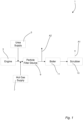
- a method for cleaning exhaust gas from the engine 3 is performed by means of the exhaust gas cleaning system 1.
- exhaust gas discharged from the engine 3 is fed in turn through the particle filter device 9, the boiler 11 and the scrubber 13 before it is released into the atmosphere.
- particle filter device 9 and Fig. 2 exhaust gas from the engine 3 is fed into the casing 15, more particularly into the exhaust gas reception space 17, via the exhaust gas inlet 25, i.e. at the height of a respective upper portion of the filter rods 33.
- the exhaust gas is fed past the perforated plate 29 through the openings 41 thereof, and through the passages between the perforated plate 29 and the two long side portions 35 of the casing 15 ( Fig. 3 ), into the exhaust gas passage 19, and especially into the intermediate and the first and second outer distributions channels 61, 63 and 65 defined therein by the filter rods 33.
- the exhaust gas conveyed through the channels 61, 63 and 65 is eventually forced into the groups 57 and 59 of filter rods 33 because of the lower exhaust gas pressure within the filter rod groups 57 and 59.
- the presence and design of the perforated plate 29 promote a more even distribution of the exhaust gas inside the exhaust gas passage 19.
- the folded first and second outer side sections 43 and 45, respectively, enables guiding of the exhaust gas towards the filter rods 33.
- the exhaust gas is filtered by penetrating the walls 53 of the filter rods 33 whereby filtered exhaust gas is received inside the filter rods 33 and soot and particulate matter is deposited on an outside surface 56 of the filter rods 33.
- the deposits on the outside surface 56 of the filter rods 33 are gradually increasing and since the exhaust gas density is higher closer to the hole plate 31, so is also the amount of deposits. Thereby, the exhaust gas inside the exhaust gas passage 19 is gradually forced downwards for penetration of the filter rod walls 53.
- the filter rods 33 are impregnated with a substance containing an oxidation catalyst as well as an reduction catalyst.
- the nitrogen oxides contained in the exhaust gas reacts, in the presence of the reduction catalyst, with ammonia, also contained in the exhaust gas and resulting from the previously discussed decomposition of urea, which results in a degradation of the nitrogen oxides into nitrogen and water. Further, the hydrocarbons contained in the exhaust gas are burned in the presence of the oxidation catalyst for reduction of the overall soot mass and regeneration of the filter rods 33.
- Filtered exhaust gas cleaned from nitrogen oxides and hydrocarbons is conveyed upwards inside the filter rods 33 and is discharged into the exhaust gas discharge space 21 via the open upper ends 49 of the filter rods 33. Thereafter, it leaves the particle filter device 9 via the exhaust gas outlet 27.
- the particle filter device 9 further comprises a soot blowing arrangement 67 arranged inside the exhaust gas discharge space 21, i.e. above the exhaust gas passage 19 and the filter rods 33.
- the soot blowing arrangement 67 comprises one gas pipe 69 for each one of the eight rows of filter rods 33, which gas pipe 69 extends parallel to the respective row of filter rods 33.
- each of the gas pipes 69 is provided with one nozzle 71 for each one of the nine filter rods 33 in each row of filter rods 33. More particularly, each of the nozzles 71 is aligned with a respective one of the filter rods 33 and arranged to blow gas, which is fed through the respective gas pipe 69, into the open upper end 39 of the respective filter rod 33. Gas is fed to the gas pipes 69 by means of an arrangement not illustrated in the figures and not further described herein.
- the soot blowing arrangement 67 is operated in response to a change in backpressure inside the particle filter device 9. More particularly, the particle filter device 9 comprises a first pressure sensor (not illustrated) arranged inside the exhaust gas passage 19 and a second pressure sensor (not illustrated) arranged inside the exhaust gas discharge space 21. When the difference between the pressures measured by means of the first and second pressure sensors exceeds a predetermined threshold value, this indicates that the soot and particulate matter deposits on the outside surface 56 of the filter rods 33 are starting to get too thick and that the soot blowing arrangement 67 should be operated. Then, short bursts of pressurized gas, e.g. air, is fed through the gas pipes 69, one of the gas pipes 69 at a time.
- pressurized gas e.g. air
- the pressurized gas is ejected from the nozzles 71 into the corresponding filter rods 33 to create a shock wave that causes loosening of the deposits from the outside surface 56 of the filter rods 33. Since the soot blowing operation is made for one row of, i.e. only a subset of the, filter rods 33 at a time, it does not require a shut-down of the particle filter device 9 which may be operated normally in the meantime. The loosened deposits fall downwards by gravity, which is possible due to the minimization of the upwards directed exhaust gas flow inside the exhaust gas passage 19. Eventually, the loosened deposits end up in the dirt collection space 23.
- the part of the casing 15 defining the dirt collection space 23 is made of stainless steel which has relatively good "sliding" properties, and collection of the deposits at the bottom of the dirt collection space 23 is facilitated. Also, the provision of the hammer or vibrator 34 on the outside of the dirt collection space 23 helps to collect the deposits at the dirt collection space bottom. When the dirt collection space 23 needs to be emptied, the mechanism 30 is operated and the deposits are discharged to the container 32.
- exhaust gas from the engine 3 is fed through the particle filter device 9, the boiler 11 and the scrubber 13 for removal of soot and particular matter, together with nitrogen oxides and hydrocarbons, and eventually also sulphur oxides, from the exhaust gas.
- soot and particulate matter from the exhaust gas adhere to the outside surface 56 of the filter rods 33.
- the soot blowing arrangement 67 is operated and gas is injected into the filter rods 33, one filter rod row after the other. Thereby, soot and particulate matter are peeled off from the filter rods 33.
- additional deeper cleaning of the particle filter device 9 may be necessary once in a while, to assure proper operation of the exhaust gas system 1.
- the exhaust gas system 1 is also arranged for operation in a second operation mode.
- the exhaust gas flow from the engine 3 to the particle filter device 9 is shut off, just like the urea flow from the urea supply 5.
- the hot gas supply 7 is activated and blows hot gas through the particle filter device 9.
- the hot gas supply 7 may comprise an electrical heater for heating gas.
- the hot gas may originate from a burner or the engine itself, possibly from before a turbocharger.
- the hot gas follows the same, above specified, way as the exhaust gas through the particle filter device 9.
- the hot gas is discharged from the exhaust gas system 1 as illustrated by arrow A2, or it is fed through the boiler 11 and possibly also the scrubber 13.
- the hot gas boosts the regeneration of the filter rods 33 by intensifying the burning of hydrocarbons remains on and in the wall 53 of the filter rods 33. After the intensified thermal regeneration, the exhaust gas system 1 is again ready for the first operation mode. Switching between the first and second operation modes can be done automatically or manually.
- Fig. 5 illustrates a particle filter device 9 of an exhaust gas cleaning system according to another embodiment of the invention.
- This particle filter device 9 is very similar to the particle filter device 9 described above with reference to Figs. 1-4 , and hereinafter, primarily the differing features will be discussed.
- the filter rods 33 are arranged in a specific pattern. More particularly, they are divided into first, second and third groups 57, 59 and 62 of filter rods.
- the third group 62 is centrally arranged inside the exhaust gas passage 19, while the first and second groups 57 and 59 are arranged on opposite sides of the third group 62.
- a total of twelve rows of filter rods 33, four rows in each of the groups, each row containing nine filter rods 33, are illustrated.
- the filter rods 33 within one and the same group of the first, second and third groups 57, 59 and 62 are arranged closer than two filter rods 33 within different ones of the groups.
- an intermediate distribution channel 61a is formed between the first and third groups 57 and 62 of filter rods 33
- an intermediate distribution channel 61b is formed between the second and third groups 59 and 62 of filter rods 33, which intermediate distribution channels 61a and 61b extend in a direction from the perforated plate 29.
- the filter rods 33 and the casing 15 of the particle filter device 9 illustrated in Fig. 5 define first and second outer distribution channels 63 and 65.
- the intermediate and first and second outer distribution channels 61a, 61b, 63 and 65 are arranged to convey the exhaust gas before it is force into the groups 57, 59 and 62 of filter rods 33 to promote a more uniform exhaust gas distribution inside the exhaust gas passage 19.
- the perforated plate 29 comprises a number of guide vanes 64 in the form of elongate plates or flanges welded onto the perforated plate 29.
- the guide vanes 64 are angled in relation to a normal direction of the perforated plate 29 so as to guide exhaust gas especially into the intermediate distribution channels 61a and 61b.
- the guide vanes 64 may extend along the complete, or only part of the, longitudinal extension of the perforated plate 29 and their design, number and position may vary depending on the prevailing circumstances, such as the size of the perforated plate 29 and the number of intermediate distribution channels.
- the guide vanes 64 could be arranged on a side of the perforated plate 29 facing away from the filter rods 33, as is illustrated in Fig. 5 , and/or on a side of the perforated plate 29 facing the filter rods 33.
- the main purpose of the guide vanes 64 is to promote a more even distribution of the exhaust gas around the filter rods 33 to improve a performance and functionality of the exhaust gas filter device 9.
- Another purpose of the guide vanes 64 is to increase the stiffness of the perforated plate.
- the soot blowing arrangement need not be arranged to blow gas into only one row of filter rods at a time.
- the soot blowing arrangement is instead arranged to blow gas into all filter rods at the same time.
- Such an embodiment may require cessation of the exhaust gas feed through the particle filter device, which in turn could require a valve at the exhaust gas inlet and/or at the exhaust gas outlet of the particle filter device.
- it may be suitable to have multiple particle filter devices of which one is always available for exhaust gas cleaning.
- the open upper ends of the filter rods may be provided with venturi inlets.
- the venturi may draw extra gas into the filter rods during soot blowing and thereby create a more powerful shock wave inside the filter rods. At the same time a possibility to use less pressurized gas is offered.
- the soot blowing arrangement need not comprise one gas pipe and one set of nozzles for each row of filter rods.
- one or more gas pipes, with associated nozzles could be movable and able to blow gas into the filter rods of more than one of the rows of filter rods.
- soot blowing arrangement need not comprise any nozzles. Instead, the gas could be ejected directly from holes in the pipe/pipes.
- the soot blowing arrangement is operated when the difference between the pressures measured by means of the first and second pressure sensors exceeds a predetermined threshold value.
- the soot blowing arrangement could instead be operated with predetermined time intervals.
- the soot blowing arrangement could be operated with predetermined time intervals unless said predetermined threshold value is exceeded, which would shorten the time between two successive operations.
- the boiler and/or the scrubber may be left out in an exhaust gas cleaning system according to the invention.
- the engine is fueled by a low sulphur fuel, then it may be possible to omit the scrubber.
- the exhaust gas system according to the invention could comprise a heating device, such as an electrical heater, for heating the exhaust gas before it is fed to the particle filter device to increase the conversion of nitrogen oxides into nitrogen and water and/or the oxidation of hydrocarbons, inside the exhaust gas passage of the particle filter device.
- This heating device could be used also for producing hot gas for the hot gas supply which is active in the second operation mode of the exhaust gas cleaning system.
- the exhaust gas system according to the invention could comprise a draft fan for overcoming the backpressure caused by the particle filter device and drawing the exhaust gas through the particle filter device, which fan could be arranged either before or after the particle filter device.
- ammonia instead of urea could be injected into the exhaust gas before it is fed to the particle filter device.
Landscapes
- Engineering & Computer Science (AREA)
- Chemical & Material Sciences (AREA)
- Combustion & Propulsion (AREA)
- Mechanical Engineering (AREA)
- General Engineering & Computer Science (AREA)
- Chemical Kinetics & Catalysis (AREA)
- Health & Medical Sciences (AREA)
- Toxicology (AREA)
- Ocean & Marine Engineering (AREA)
- Filtering Of Dispersed Particles In Gases (AREA)
- Exhaust Gas After Treatment (AREA)
- Filtering Materials (AREA)
- Exhaust Gas Treatment By Means Of Catalyst (AREA)
- Processes For Solid Components From Exhaust (AREA)
Claims (17)
- Abgasreinigungssystem (1) zum Reinigen von Abgas, welches Abgasreinigungssystem (1) eine Partikelfiltervorrichtung (9) umfasst, die wiederum Folgendes umfasst:ein Gehäuse (15),eine Vielzahl von hohlen Keramikfilterstäben (33), die mindestens teilweise innerhalb eines Abgasdurchlasses (19) des Gehäuses (15) angeordnet sind und sich vertikal und aneinander entlang erstrecken, wenn das Abgasreinigungssystem (1) eingebaut ist,einen Abgaseinlass (25), der dazu angeordnet ist, es Abgas zu ermöglichen, dem Abgasdurchlass (19) vorgelagert in das Gehäuse (15) zu strömen, undeinen Abgasauslass (27), der dazu angeordnet ist, es Abgas zu ermöglichen, dem Abgasdurchlass (19) nachgelagert aus dem Gehäuse (15) zu strömen,wobei die Partikelfiltervorrichtung (9) dazu konfiguriert ist, Abgas von dem Abgaseinlass (25) durch den Abgasdurchlass (19) und zu dem Abgasauslass (27) zu leiten, wobei die Partikelfiltervorrichtung (9) ferner Folgendes umfasst:eine perforierte Platte (29), die dem Abgaseinlass (25) nachgelagert und dem Abgasdurchlass (19) vorgelagert angeordnet ist, welche perforierte Platte (29) sich mindestens teilweise entlang der Filterstäbe (33) erstreckt und teilweise einen Abgasströmungsweg (P) von dem Abgaseinlass (25) zu dem Abgasdurchlass (19) blockiert,wobei die perforierte Platte (29) Öffnungen (41) definiert, die dazu angeordnet sind, es Abgas zu ermöglichen, in den Abgasdurchlass (19) zu strömen, wobei die Filterstäbe (33) gasdurchlässig sind, um es Abgas zu ermöglichen, während der Filterung eine jeweilige Wand (53) der Filterstäbe (33) zu durchdringen und in die Filterstäbe (33) zu strömen, und ein jeweiliges offenes oberes Ende (49) der Filterstäbe (33) mit dem Abgasauslass (27) in Verbindung steht, um es Abgas zu ermöglichen, das Gehäuse (15) zu verlassen.
- Abgasreinigungssystem (1) nach Anspruch 1, wobei die perforierte Platte (29) einen ersten und einen zweiten Außenseitenabschnitt (43, 45) umfasst, die sich gegenüberliegen, wobei mindestens ein Teil (43u) des ersten Außenseitenabschnitts (43) um eine vertikale Achse (V1) in eine Richtung zu den Filterstäben (33) hin gebogen ist.
- Abgasreinigungssystem (1) nach einem der vorhergehenden Ansprüche, wobei die perforierte Platte (29) einen Außenunterabschnitt (44) umfasst, wobei mindestens ein Teil des Außenunterabschnitts (44) um eine horizontale Achse (H1) in eine Richtung zu den Filterstäben (33) hin gebogen ist.
- Abgasreinigungssystem (1) nach einem der vorhergehenden Ansprüche, ferner umfassend einen länglichen Plattenverstärkungsvorsprung (46a, 46b), der sich von der perforierten Platte (29) zu den Filterstäben (33) hin erstreckt.
- Abgasreinigungssystem (1) nach einem der vorhergehenden Ansprüche, wobei die Filterstäbe (33) in eine Anzahl n > 1 von Gruppen (57, 59, 62) aufgeteilt sind, und wobei ein Abstand zwischen benachbarten mindestens einer Mehrheit der Filterstäbe (33) innerhalb jeder der Gruppen (57, 59, 62) < x ist, und ein Abstand zwischen benachbarten Filterstäbe aus den Filterstäben (33) von zwei benachbarten der Gruppen (57, 59, 62) > x ist, um n-1 Zwischenverteilungskanäle (61, 61a, 61b) zu bilden, wobei jeder der Zwischenverteilungskanäle (61, 61a, 61b) sich zwischen zwei benachbarten der Gruppen (57, 59, 62) erstreckt.
- Abgasreinigungssystem (1) nach Anspruch 5, wobei mindestens einer der Zwischenverteilungskanäle (61, 61a, 61b) sich in eine Richtung weg von der perforierten Platte (29) erstreckt.
- Abgasreinigungssystem (1) nach einem der vorhergehenden Ansprüche, wobei der Abgaseinlass (25) zwischen zwei imaginären getrennten horizontalen Ebenen (h1, h2) angeordnet ist, die eine Erstreckung einer oberen Hälfte (36) der perforierten Platte (29) definieren.
- Abgasreinigungssystem (1) nach einem der vorhergehenden Ansprüche, wobei die Partikelfiltervorrichtung (9) eine Rußbläseranordnung (67) umfasst, die dazu angeordnet ist, Gas in die offenen oberen Enden (39) jeweils einer Teilmenge der Filterstäbe (33) zu blasen, um Partikel zu lösen, die durch das Abgas an einer Außenfläche (56) der Teilmenge der Filterstäbe (33) abgelagert werden.
- Abgasreinigungssystem (1) nach einem der vorhergehenden Ansprüche, wobei die Filterstäbe (33) mit einer Substanz imprägniert sind, die mindestens einen ersten Katalysator umfasst.
- Verfahren zum Reinigen von Abgas mittels einer Partikelfiltervorrichtung (9), Folgendes umfassend:ein Gehäuse (15),eine Vielzahl von hohlen, gasdurchlässigen Keramikfilterstäben (33), die mindestens teilweise innerhalb eines Abgasdurchlasses (19) des Gehäuses (15) angeordnet sind und sich vertikal und aneinander entlang erstrecken, wenn das Abgassystem (1) eingebaut ist,einen Abgaseinlass (25), der dazu angeordnet ist, es Abgas zu ermöglichen, dem Abgasdurchlass vorgelagert in das Gehäuse (15) zu strömen,einen Abgasauslass (27), der dazu angeordnet ist, es Abgas zu ermöglichen, dem Abgasdurchlass (19) nachgelagert aus dem Gehäuse (15) zu strömen, undeine perforierte Platte (29), die dem Abgaseinlass (25) nachgelagert und dem Abgasdurchlass (19) vorgelagert angeordnet ist, welche perforierte Platte (29) sich mindestens teilweise entlang der Filterstäbe (33) erstreckt und teilweise einen Abgasströmungsweg (P) von dem Abgaseinlass (25) zu dem Abgasdurchlass (19) blockiert,welches Verfahren Folgendes umfasst:Speisen von Abgas in das Gehäuse (15),Speisen von Abgas durch Öffnungen (41) der perforierten Platte (29) in den Abgasdurchlass (19),Filtern von Abgas, indem ihm ermöglicht wird, eine jeweilige Wand (53) der Filterstäbe (33) zu durchdringen und in die Filterstäbe (33) zu strömen,Ablassen von Abgas durch ein jeweiliges offenes oberes Ende (39) der Filterstäbe (33), undSpeisen von Abgas aus dem Gehäuse (15).
- Verfahren nach Anspruch 10, umfassend das Leiten von Abgas innerhalb des Gehäuses (15) mittels eines ersten und eines zweiten Außenseitenabschnitts (43, 45) der perforierten Platte (29), die sich gegenüberliegen, wobei mindestens ein Teil (43u) des ersten Außenseitenabschnitts (43) um eine vertikale Achse (V1) in eine Richtung zu den Filterstäben (33) hin gebogen ist.
- Verfahren nach einem der Ansprüche 10 bis 11, umfassend das Leiten von Abgas innerhalb des Gehäuses (15) mittels eines Außenunterabschnitts (44) der perforierten Platte (29), wobei mindestens ein Teil des Außenunterabschnitts (44) um eine horizontale Achse (H1) in eine Richtung zu den Filterstäben (33) hin gebogen ist.
- Verfahren nach einem der Ansprüche 10 bis 12, umfassend das Speisen von Abgas in n-1 Zwischenverteilungskanälen (61, 61a, 61b), die innerhalb des Abgasdurchlasses (19) ausgebildet sind, wobei die Filterstäbe (33) in eine Anzahl n > 1 von Gruppen (57, 59, 62) aufgeteilt sind, und wobei ein Abstand zwischen benachbarten mindestens einer Mehrheit der Filterstäbe (33) innerhalb jeder der Gruppen (57, 59, 62) < x ist, und ein Abstand zwischen benachbarten Filterstäbe aus den Filterstäben (33) von zwei benachbarten der Gruppen (57, 59, 62) > x ist, um n-1 Zwischenverteilungskanäle (61, 61a, 61b) zu bilden, wobei jeder der Zwischenverteilungskanäle (61, 61a, 61b) sich zwischen zwei benachbarten der Gruppen (57, 59, 62) erstreckt.
- Verfahren nach einem der Ansprüche 10 bis 13, umfassend das Speisen von Abgas in das Gehäuse (15) zwischen zwei getrennten horizontalen Ebenen (h1, h2), die eine Erstreckung einer oberen Hälfte (36) der perforierten Platte (29) definieren.
- Verfahren nach einem der Ansprüche 10 bis 14, umfassend das Blasen von Gas in die offenen oberen Enden (39) jeweils einer Teilmenge der Filterstäbe (33), um Partikel zu lösen, die durch das Abgas an einer Außenfläche (56) der Teilmenge der Filterstäbe (33) abgelagert werden.
- Verfahren nach einem der Ansprüche 10 bis 15, umfassend das Versehen der Filterstäbe (33) mit einer Imprägnierung aus einer Substanz, die mindestens einen ersten Katalysator umfasst.
- Verwendung eines Abgasreinigungssystems (1) nach einem der Ansprüche 1 bis 9 zum Reinigen von Abgas.
Priority Applications (6)
| Application Number | Priority Date | Filing Date | Title |
|---|---|---|---|
| PL21173594.9T PL4089266T3 (pl) | 2021-05-12 | 2021-05-12 | Układ oczyszczania spalin i metoda oczyszczania spalin i wykorzystanie układu oczyszczania spalin |
| EP21173594.9A EP4089266B1 (de) | 2021-05-12 | 2021-05-12 | Abgasreinigungssystem und verfahren zur reinigung von abgas und verwendung des abgasreinigungssystems |
| JP2022077012A JP7675047B2 (ja) | 2021-05-12 | 2022-05-09 | 排出ガスを浄化するための排出ガス浄化システムおよび方法ならびに排出ガス浄化システムの使用 |
| KR1020220057336A KR102757699B1 (ko) | 2021-05-12 | 2022-05-10 | 배기 가스 정화 시스템 및 배기 가스 정화 방법 및 배기 가스 정화 시스템의 용도 |
| US17/740,860 US12234756B2 (en) | 2021-05-12 | 2022-05-10 | Exhaust gas cleaning system and method for cleaning exhaust gas and use of exhaust gas cleaning system |
| CN202210503347.2A CN115341977B (zh) | 2021-05-12 | 2022-05-10 | 清洁排气的排气清洁系统和方法以及排气清洁系统的使用 |
Applications Claiming Priority (1)
| Application Number | Priority Date | Filing Date | Title |
|---|---|---|---|
| EP21173594.9A EP4089266B1 (de) | 2021-05-12 | 2021-05-12 | Abgasreinigungssystem und verfahren zur reinigung von abgas und verwendung des abgasreinigungssystems |
Publications (3)
| Publication Number | Publication Date |
|---|---|
| EP4089266A1 EP4089266A1 (de) | 2022-11-16 |
| EP4089266C0 EP4089266C0 (de) | 2025-03-19 |
| EP4089266B1 true EP4089266B1 (de) | 2025-03-19 |
Family
ID=75914424
Family Applications (1)
| Application Number | Title | Priority Date | Filing Date |
|---|---|---|---|
| EP21173594.9A Active EP4089266B1 (de) | 2021-05-12 | 2021-05-12 | Abgasreinigungssystem und verfahren zur reinigung von abgas und verwendung des abgasreinigungssystems |
Country Status (6)
| Country | Link |
|---|---|
| US (1) | US12234756B2 (de) |
| EP (1) | EP4089266B1 (de) |
| JP (1) | JP7675047B2 (de) |
| KR (1) | KR102757699B1 (de) |
| CN (1) | CN115341977B (de) |
| PL (1) | PL4089266T3 (de) |
Family Cites Families (52)
| Publication number | Priority date | Publication date | Assignee | Title |
|---|---|---|---|---|
| GB312294A (en) * | 1928-02-20 | 1929-05-21 | Reginald Arthur Bird | A purifier for the exhaust gases of internal-combustion engines |
| US4276071A (en) | 1979-12-03 | 1981-06-30 | General Motors Corporation | Ceramic filters for diesel exhaust particulates |
| US4627406A (en) * | 1984-12-05 | 1986-12-09 | Kabushiki Kaisha Tsuchiya Seisakusho | Oil separator for recycled blow-by gas |
| US5497620A (en) | 1988-04-08 | 1996-03-12 | Stobbe; Per | Method of filtering particles from a flue gas, a flue gas filter means and a vehicle |
| DE3815148A1 (de) * | 1988-05-04 | 1989-11-16 | Eberspaecher J | Anordnung zur lagerung eines von abgas durchstroemten filters in einem metallischen gehaeuse |
| DE3914758A1 (de) * | 1989-05-05 | 1990-11-08 | Mann & Hummel Filter | Russfilter zur reinigung des abgastroms einer brennkraftmaschine |
| DE4111029C2 (de) * | 1991-04-05 | 1995-08-31 | Eberspaecher J | Durch Freibrennen regenerierbarer Partikelfilter für die Abgase von Brennkraftmaschinen |
| DE4229723C1 (en) * | 1992-09-05 | 1993-09-16 | Mtu Friedrichshafen Gmbh | Regeneratable filter unit of modular structure - for particle removal from diesel exhaust gas |
| DK98993D0 (da) * | 1993-09-01 | 1993-09-01 | Per Stobbe | Dust filter for hot gases |
| JP3257949B2 (ja) * | 1996-05-24 | 2002-02-18 | 日野自動車株式会社 | 排気黒煙除去装置のフィルタ再生機構 |
| JP3331919B2 (ja) * | 1997-08-29 | 2002-10-07 | 三菱自動車工業株式会社 | 内燃機関の排気ガス浄化装置 |
| JP3597713B2 (ja) | 1998-11-20 | 2004-12-08 | 株式会社タクマ | ガスフィルター装置 |
| JP3597722B2 (ja) | 1999-02-16 | 2004-12-08 | 株式会社タクマ | ガスフィルター装置 |
| JP2002219330A (ja) * | 2001-01-23 | 2002-08-06 | Babcock Hitachi Kk | 二室型湿式排煙脱硫装置 |
| US6488269B1 (en) * | 2001-05-29 | 2002-12-03 | United Microelectronics Corp. | Wet scrubber |
| JP2003293729A (ja) * | 2002-04-02 | 2003-10-15 | Purearth Inc | 炭素粒子の減少装置 |
| EP1494784A4 (de) | 2002-04-12 | 2006-02-01 | Illinois Valley Holding Compan | Vorrichtung und verfahren zum filtern von teilchen und reduzieren von nox-emissionen |
| JP2004340049A (ja) * | 2003-05-16 | 2004-12-02 | Hino Motors Ltd | 排気浄化装置 |
| JP2005230678A (ja) | 2004-02-19 | 2005-09-02 | Kenji Nakajima | 排ガス処理装置と排ガス処理方法 |
| JP2005230677A (ja) | 2004-02-19 | 2005-09-02 | Daiwa Kogyo Kk | 排ガス処理装置と排ガス処理方法 |
| CA2624857C (en) * | 2005-09-09 | 2010-12-21 | Dexwet Usa Llc | Filter module |
| JP2009262098A (ja) * | 2008-04-28 | 2009-11-12 | Ne Chemcat Corp | 選択還元触媒を用いた排気ガス浄化方法 |
| DE102008033842A1 (de) * | 2008-07-19 | 2010-02-18 | Karl-Heinz Grywotz Automobiltechnik GmbH | Partikelfilter für Diesel- und Otto-Motoren |
| CN102463015B (zh) * | 2010-11-11 | 2014-06-18 | 上海恩凯国际贸易有限公司 | 船舶废气的脱硫脱硝方法及处理装置 |
| KR101225020B1 (ko) * | 2010-12-02 | 2013-01-22 | 니혼 스핀들 세이조 가부시키가이샤 | 집진장치 |
| JP2012115793A (ja) * | 2010-12-02 | 2012-06-21 | Nippon Spindle Mfg Co Ltd | 集塵装置 |
| CN202179914U (zh) | 2011-08-09 | 2012-04-04 | 河南中材环保有限公司 | 一种陶瓷管过滤器及清灰装置 |
| ITMI20120952A1 (it) | 2012-06-01 | 2013-12-02 | Ecospray Technologies S R L | Apparato filtrante anti-particolato per motori diesel marini e metodo di funzionamento e rigenerazione di detto apparato |
| PL2698188T3 (pl) | 2012-08-17 | 2018-05-30 | Pall Corporation | Moduł filtra katalitycznego i zawierający go układ filtra katalitycznego |
| CN203108345U (zh) | 2013-03-11 | 2013-08-07 | 重庆博山工程机械设备有限公司 | 环保无功耗低成本除尘系统 |
| CN103170191A (zh) | 2013-03-11 | 2013-06-26 | 重庆博山工程机械设备有限公司 | 环保无功耗低成本除尘系统 |
| JP2016522867A (ja) | 2013-04-15 | 2016-08-04 | ハルドール・トプサー・アクチエゼルスカベット | エンジン排気ガスから微粒子物質の煤、灰及び重金属を除去するための方法及びシステム |
| TWM484457U (zh) | 2014-04-15 | 2014-08-21 | Bao Ying Filter Technology Co Ltd | 集塵陶瓷過濾裝置 |
| WO2016029926A1 (en) | 2014-08-25 | 2016-03-03 | Haldor Topsøe A/S | Method and system for the removal of particulate matter and heavy metals from engine exhaust gas |
| CN204121934U (zh) | 2014-10-14 | 2015-01-28 | 中节能大地环境修复有限公司 | 一种热脱附尾气高温除尘装置 |
| CN104289066B (zh) | 2014-10-14 | 2016-06-29 | 中节能大地环境修复有限公司 | 热脱附尾气高温除尘装置 |
| US10830117B2 (en) * | 2014-12-31 | 2020-11-10 | Cummins Emission Solutions Inc. | Compact side inlet and outlet exhaust aftertreatment system |
| CN105149092B (zh) | 2015-09-02 | 2017-08-29 | 中国科学院过程工程研究所 | 一种用于导电粉尘的除尘方法 |
| CN106268097A (zh) | 2016-09-30 | 2017-01-04 | 中国恩菲工程技术有限公司 | 烟气过滤装置 |
| CN206081976U (zh) | 2016-09-30 | 2017-04-12 | 中国恩菲工程技术有限公司 | 烟气过滤装置 |
| CN206980341U (zh) | 2017-05-26 | 2018-02-09 | 醴陵尚方窑瓷业有限公司 | 一种陶瓷过滤装置 |
| EP3437719A1 (de) | 2017-08-01 | 2019-02-06 | Alfa Laval Corporate AB | Wäscher zur reinigung eines gases |
| CN207412968U (zh) | 2017-08-23 | 2018-05-29 | 江苏省宜兴非金属化工机械厂有限公司 | 用于粉煤灰提取氧化铝工艺上的新型除尘装置 |
| CN107335296A (zh) | 2017-08-23 | 2017-11-10 | 江苏省宜兴非金属化工机械厂有限公司 | 用于粉煤灰提取氧化铝工艺上的新型除尘装置及其方法 |
| CN207680377U (zh) | 2017-12-21 | 2018-08-03 | 桐乡市致远环保科技有限公司 | 一种玻纤窑炉废气处理一体化设备 |
| CN207871778U (zh) | 2018-01-08 | 2018-09-18 | 宝盈滤材有限公司 | 一种改良的陶瓷纤维滤管结构 |
| JP6640262B2 (ja) * | 2018-03-29 | 2020-02-05 | 月島機械株式会社 | セラミックフィルタ集塵装置 |
| CN209952488U (zh) | 2019-01-21 | 2020-01-17 | 河南绿源新星环保设备有限公司 | 陶瓷滤管脱硝脱硫除尘器 |
| CN109758855A (zh) | 2019-01-21 | 2019-05-17 | 河南绿源新星环保设备有限公司 | 一种陶瓷滤管脱硝脱硫除尘器 |
| CN209752582U (zh) | 2019-03-06 | 2019-12-10 | 富利康科技股份有限公司 | 具有陶纤滤管的危险事业废弃物焚化废气戴奥辛去除设备 |
| CN211008825U (zh) * | 2019-12-19 | 2020-07-14 | 无锡亿利环保科技有限公司 | 尿素水溶液分解混合装置 |
| KR102240510B1 (ko) * | 2019-12-19 | 2021-04-15 | (주)세라컴 | 디젤 엔진용 오염물질 저감 장치 |
-
2021
- 2021-05-12 EP EP21173594.9A patent/EP4089266B1/de active Active
- 2021-05-12 PL PL21173594.9T patent/PL4089266T3/pl unknown
-
2022
- 2022-05-09 JP JP2022077012A patent/JP7675047B2/ja active Active
- 2022-05-10 CN CN202210503347.2A patent/CN115341977B/zh active Active
- 2022-05-10 KR KR1020220057336A patent/KR102757699B1/ko active Active
- 2022-05-10 US US17/740,860 patent/US12234756B2/en active Active
Also Published As
| Publication number | Publication date |
|---|---|
| JP2022176126A (ja) | 2022-11-25 |
| JP7675047B2 (ja) | 2025-05-12 |
| PL4089266T3 (pl) | 2025-06-02 |
| EP4089266C0 (de) | 2025-03-19 |
| KR102757699B1 (ko) | 2025-01-21 |
| US12234756B2 (en) | 2025-02-25 |
| CN115341977A (zh) | 2022-11-15 |
| CN115341977B (zh) | 2023-12-26 |
| KR20220154041A (ko) | 2022-11-21 |
| US20220364487A1 (en) | 2022-11-17 |
| EP4089266A1 (de) | 2022-11-16 |
Similar Documents
| Publication | Publication Date | Title |
|---|---|---|
| KR102377446B1 (ko) | 배기가스 중의 황 산화물의 양을 감소시키는 시스템 및 방법 | |
| EP2958656B1 (de) | Abgaswäscher für schiffe | |
| KR101869844B1 (ko) | 엔진 배기가스로부터 미립자 물질 그을음, 애시 및 중금속의 제거를 위한 방법 및 시스템 | |
| CA2954013A1 (en) | Method and system for the removal of particulate matter and heavy metals from engine exhaust gas | |
| EP4089266B1 (de) | Abgasreinigungssystem und verfahren zur reinigung von abgas und verwendung des abgasreinigungssystems | |
| CN220365638U (zh) | 一种发动机尾气处理装置 | |
| JP6745813B2 (ja) | エンジン排ガス又はプロセス装置から粒状物質を除去するための方法及びシステム | |
| EP3092379B1 (de) | Abgas scrubber und schiff | |
| KR101838591B1 (ko) | 오토퍼징기능을 가지는 선박의 황산화물 제거장치용 모니터링 장치 및 그 방법 | |
| CN116576002B (zh) | 一种发动机尾气净化处理装置 | |
| US20220325646A1 (en) | Exhaust gas cleaning system and method for cleaning exhaust gas and use of exhaust gas cleaning system | |
| KR102605024B1 (ko) | 오염물질 제거 기능을 갖는 소음기 | |
| KR102538614B1 (ko) | 배기가스 처리 시스템 | |
| KR102054865B1 (ko) | 역류방지수단을 가진 배기가스 처리 시스템 | |
| HK40072489A (en) | Exhaust gas cleaning system and method for cleaning exhaust gas and use of exhaust gas cleaning system | |
| HK1218273B (en) | Exhaust gas scrubber for marine vessels |
Legal Events
| Date | Code | Title | Description |
|---|---|---|---|
| PUAI | Public reference made under article 153(3) epc to a published international application that has entered the european phase |
Free format text: ORIGINAL CODE: 0009012 |
|
| STAA | Information on the status of an ep patent application or granted ep patent |
Free format text: STATUS: THE APPLICATION HAS BEEN PUBLISHED |
|
| AK | Designated contracting states |
Kind code of ref document: A1 Designated state(s): AL AT BE BG CH CY CZ DE DK EE ES FI FR GB GR HR HU IE IS IT LI LT LU LV MC MK MT NL NO PL PT RO RS SE SI SK SM TR |
|
| STAA | Information on the status of an ep patent application or granted ep patent |
Free format text: STATUS: REQUEST FOR EXAMINATION WAS MADE |
|
| 17P | Request for examination filed |
Effective date: 20230418 |
|
| RBV | Designated contracting states (corrected) |
Designated state(s): AL AT BE BG CH CY CZ DE DK EE ES FI FR GB GR HR HU IE IS IT LI LT LU LV MC MK MT NL NO PL PT RO RS SE SI SK SM TR |
|
| STAA | Information on the status of an ep patent application or granted ep patent |
Free format text: STATUS: EXAMINATION IS IN PROGRESS |
|
| 17Q | First examination report despatched |
Effective date: 20230704 |
|
| GRAP | Despatch of communication of intention to grant a patent |
Free format text: ORIGINAL CODE: EPIDOSNIGR1 |
|
| STAA | Information on the status of an ep patent application or granted ep patent |
Free format text: STATUS: GRANT OF PATENT IS INTENDED |
|
| RIN1 | Information on inventor provided before grant (corrected) |
Inventor name: KRUSE MORTENSEN, RUDDI Inventor name: HOEY HANSEN, NICK Inventor name: MOELGAARD, SOEREN |
|
| INTG | Intention to grant announced |
Effective date: 20241209 |
|
| RIN1 | Information on inventor provided before grant (corrected) |
Inventor name: KRUSE MORTENSEN, RUDDI Inventor name: HOEY HANSEN, NICK Inventor name: MOELGAARD, SOEREN |
|
| GRAS | Grant fee paid |
Free format text: ORIGINAL CODE: EPIDOSNIGR3 |
|
| GRAA | (expected) grant |
Free format text: ORIGINAL CODE: 0009210 |
|
| STAA | Information on the status of an ep patent application or granted ep patent |
Free format text: STATUS: THE PATENT HAS BEEN GRANTED |
|
| AK | Designated contracting states |
Kind code of ref document: B1 Designated state(s): AL AT BE BG CH CY CZ DE DK EE ES FI FR GB GR HR HU IE IS IT LI LT LU LV MC MK MT NL NO PL PT RO RS SE SI SK SM TR |
|
| REG | Reference to a national code |
Ref country code: GB Ref legal event code: FG4D |
|
| REG | Reference to a national code |
Ref country code: CH Ref legal event code: EP |
|
| REG | Reference to a national code |
Ref country code: DE Ref legal event code: R096 Ref document number: 602021027700 Country of ref document: DE |
|
| REG | Reference to a national code |
Ref country code: IE Ref legal event code: FG4D |
|
| PGFP | Annual fee paid to national office [announced via postgrant information from national office to epo] |
Ref country code: GB Payment date: 20250320 Year of fee payment: 5 |
|
| U01 | Request for unitary effect filed |
Effective date: 20250403 |
|
| U07 | Unitary effect registered |
Designated state(s): AT BE BG DE DK EE FI FR IT LT LU LV MT NL PT RO SE SI Effective date: 20250410 |
|
| U20 | Renewal fee for the european patent with unitary effect paid |
Year of fee payment: 5 Effective date: 20250407 |
|
| PG25 | Lapsed in a contracting state [announced via postgrant information from national office to epo] |
Ref country code: RS Free format text: LAPSE BECAUSE OF FAILURE TO SUBMIT A TRANSLATION OF THE DESCRIPTION OR TO PAY THE FEE WITHIN THE PRESCRIBED TIME-LIMIT Effective date: 20250619 |
|
| PGFP | Annual fee paid to national office [announced via postgrant information from national office to epo] |
Ref country code: PL Payment date: 20250318 Year of fee payment: 5 |
|
| PGFP | Annual fee paid to national office [announced via postgrant information from national office to epo] |
Ref country code: NO Payment date: 20250509 Year of fee payment: 5 |
|
| PG25 | Lapsed in a contracting state [announced via postgrant information from national office to epo] |
Ref country code: HR Free format text: LAPSE BECAUSE OF FAILURE TO SUBMIT A TRANSLATION OF THE DESCRIPTION OR TO PAY THE FEE WITHIN THE PRESCRIBED TIME-LIMIT Effective date: 20250319 |
|
| PGFP | Annual fee paid to national office [announced via postgrant information from national office to epo] |
Ref country code: GR Payment date: 20250516 Year of fee payment: 5 |
|
| PGFP | Annual fee paid to national office [announced via postgrant information from national office to epo] |
Ref country code: CH Payment date: 20250601 Year of fee payment: 5 |
|
| PGFP | Annual fee paid to national office [announced via postgrant information from national office to epo] |
Ref country code: TR Payment date: 20250602 Year of fee payment: 5 |
|
| REG | Reference to a national code |
Ref country code: GR Ref legal event code: EP Ref document number: 20250400893 Country of ref document: GR Effective date: 20250613 |
|
| PG25 | Lapsed in a contracting state [announced via postgrant information from national office to epo] |
Ref country code: SM Free format text: LAPSE BECAUSE OF FAILURE TO SUBMIT A TRANSLATION OF THE DESCRIPTION OR TO PAY THE FEE WITHIN THE PRESCRIBED TIME-LIMIT Effective date: 20250319 |
|
| PG25 | Lapsed in a contracting state [announced via postgrant information from national office to epo] |
Ref country code: ES Free format text: LAPSE BECAUSE OF FAILURE TO SUBMIT A TRANSLATION OF THE DESCRIPTION OR TO PAY THE FEE WITHIN THE PRESCRIBED TIME-LIMIT Effective date: 20250319 |
|
| PG25 | Lapsed in a contracting state [announced via postgrant information from national office to epo] |
Ref country code: CZ Free format text: LAPSE BECAUSE OF FAILURE TO SUBMIT A TRANSLATION OF THE DESCRIPTION OR TO PAY THE FEE WITHIN THE PRESCRIBED TIME-LIMIT Effective date: 20250319 |
|
| PG25 | Lapsed in a contracting state [announced via postgrant information from national office to epo] |
Ref country code: SK Free format text: LAPSE BECAUSE OF FAILURE TO SUBMIT A TRANSLATION OF THE DESCRIPTION OR TO PAY THE FEE WITHIN THE PRESCRIBED TIME-LIMIT Effective date: 20250319 |
|
| PG25 | Lapsed in a contracting state [announced via postgrant information from national office to epo] |
Ref country code: IS Free format text: LAPSE BECAUSE OF FAILURE TO SUBMIT A TRANSLATION OF THE DESCRIPTION OR TO PAY THE FEE WITHIN THE PRESCRIBED TIME-LIMIT Effective date: 20250719 |
|
| PLBE | No opposition filed within time limit |
Free format text: ORIGINAL CODE: 0009261 |
|
| STAA | Information on the status of an ep patent application or granted ep patent |
Free format text: STATUS: NO OPPOSITION FILED WITHIN TIME LIMIT |
|
| REG | Reference to a national code |
Ref country code: CH Ref legal event code: L10 Free format text: ST27 STATUS EVENT CODE: U-0-0-L10-L00 (AS PROVIDED BY THE NATIONAL OFFICE) Effective date: 20260128 |
|
| PG25 | Lapsed in a contracting state [announced via postgrant information from national office to epo] |
Ref country code: MC Free format text: LAPSE BECAUSE OF FAILURE TO SUBMIT A TRANSLATION OF THE DESCRIPTION OR TO PAY THE FEE WITHIN THE PRESCRIBED TIME-LIMIT Effective date: 20250319 |