EP4088929B1 - Anlage zur bearbeitung von keramik- oder steinplatten - Google Patents
Anlage zur bearbeitung von keramik- oder steinplatten Download PDFInfo
- Publication number
- EP4088929B1 EP4088929B1 EP22166431.1A EP22166431A EP4088929B1 EP 4088929 B1 EP4088929 B1 EP 4088929B1 EP 22166431 A EP22166431 A EP 22166431A EP 4088929 B1 EP4088929 B1 EP 4088929B1
- Authority
- EP
- European Patent Office
- Prior art keywords
- slab
- plant
- station
- support element
- net
- Prior art date
- Legal status (The legal status is an assumption and is not a legal conclusion. Google has not performed a legal analysis and makes no representation as to the accuracy of the status listed.)
- Active
Links
Images

Classifications
-
- B—PERFORMING OPERATIONS; TRANSPORTING
- B32—LAYERED PRODUCTS
- B32B—LAYERED PRODUCTS, i.e. PRODUCTS BUILT-UP OF STRATA OF FLAT OR NON-FLAT, e.g. CELLULAR OR HONEYCOMB, FORM
- B32B39/00—Layout of apparatus or plants, e.g. modular laminating systems
-
- B—PERFORMING OPERATIONS; TRANSPORTING
- B32—LAYERED PRODUCTS
- B32B—LAYERED PRODUCTS, i.e. PRODUCTS BUILT-UP OF STRATA OF FLAT OR NON-FLAT, e.g. CELLULAR OR HONEYCOMB, FORM
- B32B37/00—Methods or apparatus for laminating, e.g. by curing or by ultrasonic bonding
- B32B37/0046—Methods or apparatus for laminating, e.g. by curing or by ultrasonic bonding characterised by constructional aspects of the apparatus
-
- E—FIXED CONSTRUCTIONS
- E04—BUILDING
- E04C—STRUCTURAL ELEMENTS; BUILDING MATERIALS
- E04C2/00—Building elements of relatively thin form for the construction of parts of buildings, e.g. sheet materials, slabs, or panels
- E04C2/02—Building elements of relatively thin form for the construction of parts of buildings, e.g. sheet materials, slabs, or panels characterised by specified materials
- E04C2/04—Building elements of relatively thin form for the construction of parts of buildings, e.g. sheet materials, slabs, or panels characterised by specified materials of concrete or other stone-like material; of asbestos cement; of cement and other mineral fibres
- E04C2/06—Building elements of relatively thin form for the construction of parts of buildings, e.g. sheet materials, slabs, or panels characterised by specified materials of concrete or other stone-like material; of asbestos cement; of cement and other mineral fibres reinforced
-
- B—PERFORMING OPERATIONS; TRANSPORTING
- B32—LAYERED PRODUCTS
- B32B—LAYERED PRODUCTS, i.e. PRODUCTS BUILT-UP OF STRATA OF FLAT OR NON-FLAT, e.g. CELLULAR OR HONEYCOMB, FORM
- B32B2305/00—Condition, form or state of the layers or laminate
- B32B2305/38—Meshes, lattices or nets
-
- B—PERFORMING OPERATIONS; TRANSPORTING
- B32—LAYERED PRODUCTS
- B32B—LAYERED PRODUCTS, i.e. PRODUCTS BUILT-UP OF STRATA OF FLAT OR NON-FLAT, e.g. CELLULAR OR HONEYCOMB, FORM
- B32B2315/00—Other materials containing non-metallic inorganic compounds not provided for in groups B32B2311/00 - B32B2313/04
- B32B2315/02—Ceramics
-
- B—PERFORMING OPERATIONS; TRANSPORTING
- B32—LAYERED PRODUCTS
- B32B—LAYERED PRODUCTS, i.e. PRODUCTS BUILT-UP OF STRATA OF FLAT OR NON-FLAT, e.g. CELLULAR OR HONEYCOMB, FORM
- B32B2318/00—Mineral based
- B32B2318/04—Stone
-
- B—PERFORMING OPERATIONS; TRANSPORTING
- B32—LAYERED PRODUCTS
- B32B—LAYERED PRODUCTS, i.e. PRODUCTS BUILT-UP OF STRATA OF FLAT OR NON-FLAT, e.g. CELLULAR OR HONEYCOMB, FORM
- B32B37/00—Methods or apparatus for laminating, e.g. by curing or by ultrasonic bonding
- B32B37/12—Methods or apparatus for laminating, e.g. by curing or by ultrasonic bonding characterised by using adhesives
- B32B37/1284—Application of adhesive
Definitions
- the present invention refers to the sector of slab processing, in particular ceramic or stone slabs.
- the present invention relates to a plant for coupling a net, or reinforcement mat, to a ceramic or stone slab.
- the slabs - in particular large-sized slabs - can be structurally fragile, having a pair of large faces - one lower and one upper - separated by a limited thickness.
- the net holds the single pieces of the slab, preventing some of them from falling and injuring the personnel involved in the transport or installation thereof.
- the reinforcement net application procedure - that is, applying the net to the slab - envisages placing the slab to be processed onto a rigid support element, in the jargon called 'stretcher', with the lower face turned upwards and the upper face (the one with aesthetic value) in contact with the stretcher.
- the upper face of the slab is protected with an adhesive film and rested directly on the transport system without the aid of the stretcher.
- the lower face is then covered with an adhesive substance, onto which the net is deposited.
- the slab is introduced into a drying oven in order to dry the adhesive substance, thus fixing the net on the slab.
- the slab In order to carry out the reinforcement net application procedure, the slab is lifted from a loading station, where it lies with the lower face turned downwards, and is rotated so as to be placed onto the stretcher (or onto the loading system if the upper face is protected by adhesive film) with the lower face turned upwards. This is necessary for depositing the net and the adhesive substance onto the lower face of the slab. Furthermore, at the end of the processing, the slab is rotated again so as to be deposited in an unloading station with the lower slab facing downwards.
- Plants capable of transporting concrete panels or ceramic slabs are known from US10562206B2 and WO2018/193416 . While the former refers to the production of cementitious panels, the latter discloses a resin application line for providing slabs with a reinforcement net.
- An object of the present invention is to overcome the drawbacks of the prior art.
- the present invention is directed to a plant for processing ceramic or stone slabs, comprising:
- the second tilting station is also configured to move the rigid support element towards a recovery transport line when the slab is lifted from the rigid support element.
- the recovery transport line is adapted to transport the rigid support element from the second tilting station to the first tilting station.
- the recovery transport line is suitable for transporting the rigid support element arranged with a longitudinal axis transverse to an advancement direction of the support element. This allows to further reduce the overall dimensions.
- the plant comprises a loading/unloading station (e.g., a hoist crane or other operatorless automatic loading system, such as an anthropomorphic or Cartesian robot) suitable for lifting the slab from a loading zone and deposit it on an initial transport line suitable for moving the slab towards the first tilting station, the loading/unloading station being also suitable for lifting the slab from the end transport line to place it in an unloading zone.
- a loading/unloading station e.g., a hoist crane or other operatorless automatic loading system, such as an anthropomorphic or Cartesian robot
- This solution allows loading and unloading slabs from a single, conveniently located station in the plant, thereby optimising plant costs and minimising the spaces occupied.
- the adhesive deposition station comprises a pair of tanks suitable for containing different chemical compounds, and a pair of pumps suitable for taking the chemical compounds from the two tanks and pumping them at a pressure greater than 15MPa towards a dispenser.
- the chemical compounds are pumped into respective pumping conduits reaching a mixing unit interposed between the pumps and a dispenser.
- the mixing unit comprises a valve with a hydraulic actuator adapted to intercept the inlet ports of the pumping conduits in the mixing unit to allow or prevent the chemical compounds from entering the mixing unit.
- the plant comprises a rolling station which, upon arrival of the slab, brings a rolling head above the centre of the slab, then lowers the rolling head until the net is pressed against the slab. Once positioned on the net, the station moves the rolling head from the centre towards an edge of the slab following a first direction. Once it has reached the edge of the slab, the rolling head is raised and returned to the centre of the slab. The rolling station then repeats the operation by lowering the rolling head until it touches the slab and by moving it in another direction different from the first.
- This solution which can be implemented for example with a five-axis Cartesian gantry robot capable of moving the rolling head along five axes, makes it possible to avoid making excessively long rollings and thus reduce the risk of the roller, by being filled with glue, lifting the net from the slab.
- the plant comprises a U-shaped transport line suitable for moving the rigid support element with the slab according to a U-shaped path, so as to reduce the overall length of the plant.
- the U-shaped transport line is suitable for transporting the rigid support element from the rolling station to the drying oven. This solution, in fact, seems preferable to reduce the dimensions of the plant.
- the rigid support element comprises a wooden slab element coated with a material refractory to the adhesive, for example a polypropylene (or derivative) sheet if the adhesive is polyurethane-based.
- the rigid support element further comprises a cushioning layer, for example a layer of expanded material of Polyethylene or a derivative thereof with a thickness from 5 to 10mm, interposed between the wooden slab element and the coating material.
- a cushioning layer for example a layer of expanded material of Polyethylene or a derivative thereof with a thickness from 5 to 10mm, interposed between the wooden slab element and the coating material.
- FIG. 1 a plant 1 for processing ceramic or stone slabs (indicated with reference L) according to an embodiment of the present invention is illustrated.
- the slab L is taken from a loading zone 17 by means of a jib crane with hoist 16 that allows it to be lifted and deposited on an initial transport line 2, in particular a large format transport line, i.e. a roller transport line for large-sized slabs, for example greater than 1000x2000 mm.
- the loading zone can be, for example, a storage crate, or an A-frame stand or a loading plane, while lifting means other than the jib crane can be provided for lifting the slab, such as robots equipped with suction cups or other means for gripping the slab.
- the slab L is deposited on the large format transport line 2 with the upper face L1 facing upwards, to be then moved along the different stations of the plant 1 by a movement group 3.
- the movement group 3 comprises transport elements that are per se known and will therefore not be described in detail in the following.
- the movement group comprises one or more roller and/or conveyor belt modules, each associated with a respective station and/or a transition region between two adjacent stations, according to criteria per se known and therefore not described in detail for brevity's sake.
- a transport line refers to a line that can have rollers and/or bands and/or belts.
- the slab L reaches a tilting station 4 where it is lifted, tilted and placed on a stretcher B with the lower face L2 facing upwards.
- Tilting stations are per se known in the industry and can, for example, make use of a suction cup group that acts on the lower face of the slab to pick it up and tilt it.
- the stretcher B illustrated in Figures 3 and 4 , comprises a wooden slab element 41 coated with a coating material 42 refractory to polyurethane, i.e. such that it does not bind to the polyurethane under environmental conditions.
- the coating material 42 may be a polyethylene sheet or a derivative thereof, in particular a polypropylene sheet.
- the stretcher B further comprises a cushioning layer, for example a layer of expanded material of Polyethylene or a derivative thereof, interposed between the wooden element 41 and the coating material 42.
- the cushioning layer 43 can be, for example, a mat of expanded material of Polyethylene or derivative with a thickness from 5 mm to 10 mm.
- the stretcher B also comprises a metal frame 44 which holds the coating material 42 and the cushioning material 43 in place on the wooden element 41.
- the slab L is moved to an adhesive deposition station 5 configured to deposit an adhesive A on the net R arranged on the stretcher B - as schematically illustrated in Figure 7 .
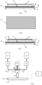
- the adhesive deposition station 5 (of which a block diagram is shown in Figure 8 ) comprises an actuator 51 configured to move along two axes - substantially parallel to a plane on which the stretcher B lies.
- the actuator 51 is operated to move an apparatus 52 for dispensing the adhesive substance over the entire lower face L2 of the slab resting on the stretcher B.
- the actuator 51 belongs to the type of the so-called Cartesian gantry robot or it can be an anthropomorphic arm.
- the dispensing apparatus 52 is configured to apply a uniform layer of adhesive on the lower face L2 of the slab.
- the dispensing apparatus 52 is a comb-type, airless-type or airbrush-type dispensing apparatus.
- the adhesive deposition station 5 comprises an adhesive pumping module 53 provided with a pair of tanks 54 intended to store two different substances, which, suitably mixed at the time of dispensing, constitute the adhesive A which is deposited on the slab L.
- the pumping module comprises two volumetric pumps 55, each of which draws from a respective tank 54 and pump a respective component of the adhesive A in predetermined quantity and pressure sending it to the dispenser.
- the pumps and the dispensing head are configured to operate at pressures comprised between 10Bar and 150Bar. Alternatively, they could be pumps operating at pressures above 150Bar (i.e. 15MPa, 15 mega Pascal).
- the pumps 55 pump the respective chemical compounds into pumping conduits 56 that end up in a mixing unit 57, which comprises a valve 58 with a hydraulic actuator 59.
- the valve 58 intercepts the inlet ports of the pumping conduits 56 in the mixing unit 57 to allow or prevent chemical compounds from entering the mixing unit 57.
- the valve 58 allows the chemical compounds pumped at high pressure by the pumps 55 to enter the mixing unit, they collide and descend by pressure into a static mixer 60 where mixing takes place.
- the adhesive A obtained by mixing the chemical compounds contained in the two tanks then reaches the dispenser 52.
- the adhesive A is of the polyurethane-based type, therefore the two tanks 54 of the pumping module 53 are loaded with polyols and isocyanate, respectively.
- the two tanks 54 of the pumping module 53 are loaded with an epoxy resin and the catalyst thereof, respectively.
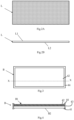
- Figure 5 shows, in section, the stretcher B with the slab L to which the adhesive A is applied at the exit of the adhesive deposition station 5.
- the stretcher with the slab covered with adhesive then continues on its way until it reaches a reinforcement net application station 6 configured to deposit a net R on the adhesive A.
- the net R - schematically illustrated in Figure 6 - is a substantially laminar reticular structure.
- the net R can be substantially constituted by a mesh made of fibre glass or other synthetic material.
- the reinforcement net application station 6 comprises a reinforcement net application module (in jargon also called a sheet laying device) loaded with a net reel and arranged to lay the net, and cutting means for cutting the net to the appropriate length, for example equal to or less than the lower face L2 of the slab L.
- the cutting means may be included in the reinforcement net application modules or be separate from them.
- the slab and stretcher assembly looks like in Figure 7 .
- the stretcher B is moved up to a rolling station 7 set up for pressing the net R onto the adhesive A so that the net R adheres to the slab L.
- the rolling station 7 comprises a five-axis Cartesian gantry robot capable of moving a rolling head along five axes.
- the Cartesian gantry is preferably configured as follows: upon arrival of the slab, the gantry brings the rolling head above the centre of face L2 of the slab, then lowers it until it presses the net against the slab. Once positioned on the net, the rolling head is moved from the centre towards an edge of the slab following a first direction. Once it has reached the edge of the slab, the head is lifted, returned to the centre and lowered again against the net; the head is then moved along another direction different from the first. The process is then repeated several times by rolling the net in different directions so that it adheres to the slab.
- the stretcher B with the slab L is then moved towards an oven 8 by means of a pair of 90° lift benches with roller conveyor 9 and a large format transport line 10.
- Each of the 90° lift benches with roller conveyor 9 allows the direction of movement of the slab in the plant to be rotated by 90°, making de facto a U-turn of the movement direction.
- the large format transport line 10, for example of the belt type, is suitable for transporting the slab arranged transversely to the advancement direction of the slab, i.e. with the smaller dimension of the face L2 arranged in the advancement direction of the slab L. This allows the length of the plant to be reduced.
- the drying oven 8 is configured to heat the assembly, consisting substantially of the slab L and the net R coated with adhesive A, to a predetermined temperature - for example comprised between 40 and 50 °C.
- the drying oven 8 is configured to dry the adhesive A such that the net R is firmly bound to the slab L.
- the drying oven 8 is preferably a ventilated oven, however other types of ovens may be envisaged.
- the stretcher B With the slab on the top, is moved, through a large format transport line 11, as far as a tilting station 12.
- the slab L is lifted from the stretcher B, tilted and placed, with the lower face L1 facing downwards, on a large format transport line 13, at the end of which it can be unloaded by means of the hoist crane 16 which lifts it from the transport line 13 and positions it in an unloading zone 14 which, in the example considered here, is a rotating fifth wheel.
- the unloading zone 14 may be a storage box, or an A-frame stand or a support plane.
- the tilting station 12 further comprises a movable roller conveyor which intervenes to move the stretcher B towards a transport line 15 when the slab L is lifted from the stretcher B.
- the recovery transport line 15 is of a type suitable for transporting large format slabs, and is preferably of the belt type; moreover, the recovery transport line 15 is suitable for transporting the slab arranged transversely to the advancement direction of the slab, i.e. with the smaller dimension of the face L2 arranged in the advancement direction of the slab L.
- a brushing station configured to brush the stretcher B before it is put back into circulation in the plant can be arranged at the recovery transport line 15.
- the rolling station 7 may be replaced by a station in which a squeegee (or several squeegees where appropriate) is used instead of a roller to make the net adhere to the slab.
- the reinforcement net application station 6 can comprise several reinforcement net application modules, each provided with a different net roll, so that different nets R can be laid on different types of slabs.
- the plant can then be fitted with a bridge ladder 18, preferably movable on wheels, to allow access to the internal zone of the plant for maintenance thereof.
- the stations can be arranged differently, albeit in the same order as described above. That is to say that the stations can be placed at different points in the space and connected by means of transport lines of different types and that they take different routes depending on the needs.
- the oven could be in line with the reinforcement net application station and the plant provided with a U-bent transport line for transporting the stretcher up to the tilting station 12.
- the oven could be in line with the reinforcement net application station and the plant provided with a U-bent transport line for transporting the stretcher up to the tilting station 12.
- several arrangements are possible that allow to create a closed-loop plant, in which the stretcher continues to turn without being unloaded from the plant.
- transport lines may be of a different type from those described depending on the needs.
Landscapes
- Engineering & Computer Science (AREA)
- Architecture (AREA)
- Civil Engineering (AREA)
- Structural Engineering (AREA)
- Cultivation Receptacles Or Flower-Pots, Or Pots For Seedlings (AREA)
- Cultivation Of Seaweed (AREA)
- Adhesives Or Adhesive Processes (AREA)
- Handcart (AREA)
Claims (11)
- Anlage (1) zum Bearbeiten von Keramik- oder Steinplatten, umfassend:- eine erste Kippstation (4) zum Anheben einer Platte (L) und zum Legen auf ein starres Trägerelement (B) mit der Fläche nach oben zeigend, die mit einem Bewehrungsnetz (L2) bereitgestellt wird;- eine Klebstoffauftragungsstation (5), die geeignet ist, eine Klebstoffsubstanz (A) auf die Fläche, die mit einem Bewehrungsnetz (L2) bereitgestellt wird, aufzutragen, wobei die Klebstoffsubstanz (A) geeignet ist, ein Bewehrungsnetz (R) auf der Fläche der Platte (L), die mit einem Bewehrungsnetz (L2) bereitgestellt wird, zu befestigen,- eine Bewehrungsnetzaufbringungsstation (6) zum Legen des Netzes (R) auf die Klebstoffsubstanz, die auf der Fläche, die mit einem Bewehrungsnetz (L2) bereitgestellt wird, angeordnet ist;- einen Trockenofen (8), der konfiguriert ist, um die Platte (L), auf die das Netz (R) auf der Fläche aufgebracht wird, die mit einem Verstärkungsnetz (L2) bereitgestellt wird, aufzunehmen und die Klebstoffsubstanz (A) zu trocknen, und- eine zweite Kippstation (12), die geeignet istdadurch gekennzeichnet, dass- das starre Trägerelement mit der aus dem Ofen kommenden Platte aufzunehmen,- die Platte (L) von dem starren Trägerelement (B) zu heben- die Platte (L) zu kippen und die Platte mit dem Netz (R) nach unten zeigend auf ein Endtransportband (13) zu legen, das für den Transport der Platte zu einer Entladeposition geeignet ist,die zweite Kippstation auch konfiguriert ist, um das starre Trägerelement (B) in Richtung einer Rückholtransportlinie (15) zu bewegen, wenn die Platte (L) von dem starren Trägerelement (B) gehoben wird,und dass die Rückholtransportlinie (15) geeignet ist, das starre Trägerelement (B) von der zweiten Kippstation (12) zur ersten Kippstation (4) zu transportieren.
- Anlage (1) gemäß Anspruch 1, wobei die Rückholtransportlinie (15) geeignet ist, das starre Trägerelement (B), das mit einer Längsachse quer zu einer Vorschubrichtung des Trägerelements angeordnet ist, zu transportieren.
- Anlage (1) gemäß Anspruch 1 oder 2, ferner umfassend eine Lade-/Entladestation (16), die geeignet ist, die Platte aus einer Ladezone zu heben und sie auf einer Anfangstransportlinie abzulegen, die geeignet ist, die Platte zur ersten Kippstation (4) zu bewegen, wobei die Lade-/Entladestation (16) ferner geeignet ist, die Platte von der Endtransportlinie zu heben, um sie in einer Entladezone zu positionieren.
- Anlage (1) gemäß einem der vorhergehenden Ansprüche, wobei die Klebstoffauftragungsstation (5) ein Paar von Tanks (54), die geeignet sind, verschiedene chemische Verbindungen zu enthalten, und ein Paar von Pumpen (55) umfasst, die geeignet sind, die chemischen Verbindungen aus den beiden Tanks zu entnehmen und sie mit einem Druck von mehr als 15 MPa zu einem Verteiler (52) zu pumpen, wobei die chemischen Verbindungen in entsprechende Pumpleitungen (56) gepumpt werden, die eine Mischeinheit (57, 60) erreichen, die zwischen den Pumpen (55) und einem Verteiler (52) angeordnet ist, und wobei die Mischeinheit (57) ein Ventil (58), das eine hydraulischen Betätigung aufweist, umfasst, die geeignet ist, um die Einlassöffnungen der Pumpleitungen (56) in der Mischeinheit (57) zu unterbrechen, um ein Eintreten der chemischen Verbindungen in die Mischeinheit zu ermöglichen oder zu verhindern.
- Anlage (1) gemäß einem der vorhergehenden Ansprüche, ferner umfassend eine Walzstation (7), die konfiguriert ist, um:a. bei Ankunft der Platte einen Walzenkopf über die Mitte der Fläche der Platte zu bringen, die mit einem Bewehrungsnetz (L2) bereitgestellt wird,b. dann den Walzenkopf abzusenken, bis das Netz gegen die Platte gedrückt wird,c. nach der Positionierung auf dem Netz den Walzenkopf von der Mitte in Richtung eines Randes der Platte in eine erste Richtung zu bewegen,d. nachdem er den Rand der Platte erreicht hat, den Walzenkopf zu heben, unde. den Kopf wieder in die Mitte zurückzubringen, ihn abzusenken, bis er die Platte berührt und ihn in eine andere Richtung als die erste zu bewegen.
- Anlage (1) gemäß Anspruch 5, wobei die Walzstation (7) einen fünfachsigen kartesischen Portalroboter umfasst, mit der Fähigkeit, den Walzenkopf entlang von fünf Achsen zu bewegen.
- Anlage (1) gemäß einem der vorhergehenden Ansprüche, ferner umfassend eine U-förmige Transportlinie (9, 10), die geeignet ist, das starre Trägerelement (B) mit der Platte entlang einer U-förmigen Bahn zu bewegen.
- Anlage (1) gemäß Anspruch 7, wobei die U-förmige Transportlinie geeignet ist, das starre Trägerelement (B) von der Walzstation (7) zum Trockenofen (8) zu transportieren.
- Anlage (1) gemäß einem der vorhergehenden Ansprüche, wobei das starre Trägerelement (B) ein hölzernes Plattenelement (41) umfasst, das mit einem Material (42) beschichtet ist, das gegenüber der Klebstoffsubstanz resistent ist.
- Anlage (1) gemäß Anspruch 9, wobei das starre Trägerelement (B) ferner eine Polsterschicht, beispielsweise eine Schicht aus geschäumtem Material aus Polyethylen oder einem Derivat davon, umfasst, die zwischen dem hölzernen Plattenelement (41) und dem Beschichtungsmaterial (42) angeordnet ist, wobei die Polsterschicht geeignet ist, unter dem Gewicht der Platte (L) so zusammengedrückt zu werden, um an der Kante der Platte zu haften, sobald diese auf dem starren Trägerelement (B) gelagert ist.
- Anlage (1) gemäß Anspruch 10, wobei das starre Trägerelement (B) auch einen Metallrahmen (44) umfasst, der das Beschichtungsmaterial (42) und das Polstermaterial (43) auf dem hölzernen Element (41) festhält.
Applications Claiming Priority (1)
| Application Number | Priority Date | Filing Date | Title |
|---|---|---|---|
| IT102021000011837A IT202100011837A1 (it) | 2021-05-10 | 2021-05-10 | Impianto e metodo per la stuoiatura di lastre ceramiche o in pietra |
Publications (3)
| Publication Number | Publication Date |
|---|---|
| EP4088929A1 EP4088929A1 (de) | 2022-11-16 |
| EP4088929C0 EP4088929C0 (de) | 2023-08-23 |
| EP4088929B1 true EP4088929B1 (de) | 2023-08-23 |
Family
ID=77022062
Family Applications (1)
| Application Number | Title | Priority Date | Filing Date |
|---|---|---|---|
| EP22166431.1A Active EP4088929B1 (de) | 2021-05-10 | 2022-04-04 | Anlage zur bearbeitung von keramik- oder steinplatten |
Country Status (2)
| Country | Link |
|---|---|
| EP (1) | EP4088929B1 (de) |
| IT (1) | IT202100011837A1 (de) |
Families Citing this family (2)
| Publication number | Priority date | Publication date | Assignee | Title |
|---|---|---|---|---|
| IT202200023997A1 (it) * | 2022-11-22 | 2024-05-22 | Elmag Spa | Impianto per la produzione di pannelli multistrato e relativo metodo di produzione dei pannelli multistrato |
| CN117584591B (zh) * | 2023-12-04 | 2026-01-30 | 合肥陶陶新材料科技有限公司 | 陶瓷板背网贴附设备 |
Family Cites Families (2)
| Publication number | Priority date | Publication date | Assignee | Title |
|---|---|---|---|---|
| WO2018193416A1 (en) * | 2017-04-21 | 2018-10-25 | Simec S.P.A. | Resin line for manufacturing reinforced stone or ceramic slabs |
| US10562206B2 (en) * | 2017-06-05 | 2020-02-18 | National Gypsum Properties, Llc | Cementitious panels, and systems and methods for manufacturing cementitious panels |
-
2021
- 2021-05-10 IT IT102021000011837A patent/IT202100011837A1/it unknown
-
2022
- 2022-04-04 EP EP22166431.1A patent/EP4088929B1/de active Active
Also Published As
| Publication number | Publication date |
|---|---|
| EP4088929A1 (de) | 2022-11-16 |
| IT202100011837A1 (it) | 2022-11-10 |
| EP4088929C0 (de) | 2023-08-23 |
Similar Documents
| Publication | Publication Date | Title |
|---|---|---|
| EP4088929A1 (de) | Anlage zur bearbeitung von keramik- oder steinplatten | |
| US8997969B2 (en) | Production cell with a workpiece transfer device, and transport device for workpieces and part carriers | |
| CN214292660U (zh) | 自动喷砂处理生产线 | |
| US12070828B2 (en) | Cell and method for operating a cell of at least two linked horizontal machining centers | |
| JP2005008409A (ja) | グリーンタイヤ積載用パレットの自動入出庫システム | |
| CN106042185B (zh) | 全自动化复合板生产线 | |
| KR101307121B1 (ko) | 패널 이송장치 및 허니컴 패널의 제조방법 | |
| KR102576141B1 (ko) | 적층장치를 이용한 반도체 부품 자동 적층 시스템 | |
| EP4000927B1 (de) | Anlage und verfahren zur anwendung eines verstärkungsnetzes auf keramik- oder steinplatten | |
| JP2010150741A (ja) | 型枠加工装置 | |
| US6022439A (en) | Method for assembling a pair of members | |
| KR101650403B1 (ko) | 가구용 합판 도료장치 | |
| JP3242002B2 (ja) | 板材の散水方法及び散水システム | |
| JP2009227411A (ja) | 多孔質板の自動化生産システム | |
| JP3908296B2 (ja) | 遊技機製造用空パレット回収装置 | |
| CZ7381U1 (cs) | Zařízení pro postřikování polotovarů krytinových tašek | |
| CA3153107C (en) | Cell and method for operating a cell of at least two linked horizontal machining centers | |
| EP4385733A2 (de) | Anlage zur herstellung von mehrschichtigen platten und entsprechendes verfahren zur herstellung von mehrschichtigen platten | |
| JP4781167B2 (ja) | 横型多段プレス装置の板材保持構造 | |
| EP3990194B1 (de) | Anlage zur oberflächenbearbeitung von produkten | |
| JP2009120339A (ja) | パレットを用いたパネルの積取装置 | |
| IT202300027198A1 (it) | Lastra dotata di stuoia | |
| CN108545537A (zh) | 生物面膜生产用铺平流水线装置 | |
| JP2968212B2 (ja) | 煉瓦生角の接触面に銀砂を介在させる銀砂付着装置 | |
| DE202010010109U1 (de) | Vorrichtung zum horizontalen Handhaben von großflächigen, zerbrechlichen Substanzen |
Legal Events
| Date | Code | Title | Description |
|---|---|---|---|
| PUAI | Public reference made under article 153(3) epc to a published international application that has entered the european phase |
Free format text: ORIGINAL CODE: 0009012 |
|
| STAA | Information on the status of an ep patent application or granted ep patent |
Free format text: STATUS: THE APPLICATION HAS BEEN PUBLISHED |
|
| AK | Designated contracting states |
Kind code of ref document: A1 Designated state(s): AL AT BE BG CH CY CZ DE DK EE ES FI FR GB GR HR HU IE IS IT LI LT LU LV MC MK MT NL NO PL PT RO RS SE SI SK SM TR |
|
| STAA | Information on the status of an ep patent application or granted ep patent |
Free format text: STATUS: REQUEST FOR EXAMINATION WAS MADE |
|
| 17P | Request for examination filed |
Effective date: 20221124 |
|
| RBV | Designated contracting states (corrected) |
Designated state(s): AL AT BE BG CH CY CZ DE DK EE ES FI FR GB GR HR HU IE IS IT LI LT LU LV MC MK MT NL NO PL PT RO RS SE SI SK SM TR |
|
| GRAP | Despatch of communication of intention to grant a patent |
Free format text: ORIGINAL CODE: EPIDOSNIGR1 |
|
| STAA | Information on the status of an ep patent application or granted ep patent |
Free format text: STATUS: GRANT OF PATENT IS INTENDED |
|
| RIC1 | Information provided on ipc code assigned before grant |
Ipc: E04C 2/06 20060101ALI20230309BHEP Ipc: B32B 39/00 20060101AFI20230309BHEP |
|
| INTG | Intention to grant announced |
Effective date: 20230404 |
|
| GRAS | Grant fee paid |
Free format text: ORIGINAL CODE: EPIDOSNIGR3 |
|
| GRAA | (expected) grant |
Free format text: ORIGINAL CODE: 0009210 |
|
| STAA | Information on the status of an ep patent application or granted ep patent |
Free format text: STATUS: THE PATENT HAS BEEN GRANTED |
|
| AK | Designated contracting states |
Kind code of ref document: B1 Designated state(s): AL AT BE BG CH CY CZ DE DK EE ES FI FR GB GR HR HU IE IS IT LI LT LU LV MC MK MT NL NO PL PT RO RS SE SI SK SM TR |
|
| REG | Reference to a national code |
Ref country code: GB Ref legal event code: FG4D |
|
| REG | Reference to a national code |
Ref country code: CH Ref legal event code: EP |
|
| REG | Reference to a national code |
Ref country code: DE Ref legal event code: R096 Ref document number: 602022000363 Country of ref document: DE |
|
| REG | Reference to a national code |
Ref country code: IE Ref legal event code: FG4D |
|
| U01 | Request for unitary effect filed |
Effective date: 20230920 |
|
| U07 | Unitary effect registered |
Designated state(s): AT BE BG DE DK EE FI FR IT LT LU LV MT NL PT SE SI Effective date: 20230928 |
|
| PG25 | Lapsed in a contracting state [announced via postgrant information from national office to epo] |
Ref country code: GR Free format text: LAPSE BECAUSE OF FAILURE TO SUBMIT A TRANSLATION OF THE DESCRIPTION OR TO PAY THE FEE WITHIN THE PRESCRIBED TIME-LIMIT Effective date: 20231124 |
|
| PG25 | Lapsed in a contracting state [announced via postgrant information from national office to epo] |
Ref country code: IS Free format text: LAPSE BECAUSE OF FAILURE TO SUBMIT A TRANSLATION OF THE DESCRIPTION OR TO PAY THE FEE WITHIN THE PRESCRIBED TIME-LIMIT Effective date: 20231223 |
|
| PG25 | Lapsed in a contracting state [announced via postgrant information from national office to epo] |
Ref country code: RS Free format text: LAPSE BECAUSE OF FAILURE TO SUBMIT A TRANSLATION OF THE DESCRIPTION OR TO PAY THE FEE WITHIN THE PRESCRIBED TIME-LIMIT Effective date: 20230823 Ref country code: NO Free format text: LAPSE BECAUSE OF FAILURE TO SUBMIT A TRANSLATION OF THE DESCRIPTION OR TO PAY THE FEE WITHIN THE PRESCRIBED TIME-LIMIT Effective date: 20231123 Ref country code: IS Free format text: LAPSE BECAUSE OF FAILURE TO SUBMIT A TRANSLATION OF THE DESCRIPTION OR TO PAY THE FEE WITHIN THE PRESCRIBED TIME-LIMIT Effective date: 20231223 Ref country code: HR Free format text: LAPSE BECAUSE OF FAILURE TO SUBMIT A TRANSLATION OF THE DESCRIPTION OR TO PAY THE FEE WITHIN THE PRESCRIBED TIME-LIMIT Effective date: 20230823 Ref country code: GR Free format text: LAPSE BECAUSE OF FAILURE TO SUBMIT A TRANSLATION OF THE DESCRIPTION OR TO PAY THE FEE WITHIN THE PRESCRIBED TIME-LIMIT Effective date: 20231124 |
|
| PG25 | Lapsed in a contracting state [announced via postgrant information from national office to epo] |
Ref country code: PL Free format text: LAPSE BECAUSE OF FAILURE TO SUBMIT A TRANSLATION OF THE DESCRIPTION OR TO PAY THE FEE WITHIN THE PRESCRIBED TIME-LIMIT Effective date: 20230823 |
|
| PG25 | Lapsed in a contracting state [announced via postgrant information from national office to epo] |
Ref country code: ES Free format text: LAPSE BECAUSE OF FAILURE TO SUBMIT A TRANSLATION OF THE DESCRIPTION OR TO PAY THE FEE WITHIN THE PRESCRIBED TIME-LIMIT Effective date: 20230823 |
|
| PG25 | Lapsed in a contracting state [announced via postgrant information from national office to epo] |
Ref country code: SM Free format text: LAPSE BECAUSE OF FAILURE TO SUBMIT A TRANSLATION OF THE DESCRIPTION OR TO PAY THE FEE WITHIN THE PRESCRIBED TIME-LIMIT Effective date: 20230823 Ref country code: RO Free format text: LAPSE BECAUSE OF FAILURE TO SUBMIT A TRANSLATION OF THE DESCRIPTION OR TO PAY THE FEE WITHIN THE PRESCRIBED TIME-LIMIT Effective date: 20230823 Ref country code: ES Free format text: LAPSE BECAUSE OF FAILURE TO SUBMIT A TRANSLATION OF THE DESCRIPTION OR TO PAY THE FEE WITHIN THE PRESCRIBED TIME-LIMIT Effective date: 20230823 Ref country code: CZ Free format text: LAPSE BECAUSE OF FAILURE TO SUBMIT A TRANSLATION OF THE DESCRIPTION OR TO PAY THE FEE WITHIN THE PRESCRIBED TIME-LIMIT Effective date: 20230823 Ref country code: SK Free format text: LAPSE BECAUSE OF FAILURE TO SUBMIT A TRANSLATION OF THE DESCRIPTION OR TO PAY THE FEE WITHIN THE PRESCRIBED TIME-LIMIT Effective date: 20230823 |
|
| REG | Reference to a national code |
Ref country code: DE Ref legal event code: R097 Ref document number: 602022000363 Country of ref document: DE |
|
| U20 | Renewal fee for the european patent with unitary effect paid |
Year of fee payment: 3 Effective date: 20240423 |
|
| PLBE | No opposition filed within time limit |
Free format text: ORIGINAL CODE: 0009261 |
|
| STAA | Information on the status of an ep patent application or granted ep patent |
Free format text: STATUS: NO OPPOSITION FILED WITHIN TIME LIMIT |
|
| 26N | No opposition filed |
Effective date: 20240524 |
|
| PG25 | Lapsed in a contracting state [announced via postgrant information from national office to epo] |
Ref country code: MC Free format text: LAPSE BECAUSE OF FAILURE TO SUBMIT A TRANSLATION OF THE DESCRIPTION OR TO PAY THE FEE WITHIN THE PRESCRIBED TIME-LIMIT Effective date: 20230823 |
|
| PG25 | Lapsed in a contracting state [announced via postgrant information from national office to epo] |
Ref country code: MC Free format text: LAPSE BECAUSE OF FAILURE TO SUBMIT A TRANSLATION OF THE DESCRIPTION OR TO PAY THE FEE WITHIN THE PRESCRIBED TIME-LIMIT Effective date: 20230823 |
|
| PG25 | Lapsed in a contracting state [announced via postgrant information from national office to epo] |
Ref country code: IE Free format text: LAPSE BECAUSE OF NON-PAYMENT OF DUE FEES Effective date: 20240404 |
|
| U20 | Renewal fee for the european patent with unitary effect paid |
Year of fee payment: 4 Effective date: 20250424 |
|
| PG25 | Lapsed in a contracting state [announced via postgrant information from national office to epo] |
Ref country code: CY Free format text: LAPSE BECAUSE OF FAILURE TO SUBMIT A TRANSLATION OF THE DESCRIPTION OR TO PAY THE FEE WITHIN THE PRESCRIBED TIME-LIMIT; INVALID AB INITIO Effective date: 20220404 |
|
| REG | Reference to a national code |
Ref country code: CH Ref legal event code: H13 Free format text: ST27 STATUS EVENT CODE: U-0-0-H10-H13 (AS PROVIDED BY THE NATIONAL OFFICE) Effective date: 20251125 |
|
| PG25 | Lapsed in a contracting state [announced via postgrant information from national office to epo] |
Ref country code: TR Free format text: LAPSE BECAUSE OF FAILURE TO SUBMIT A TRANSLATION OF THE DESCRIPTION OR TO PAY THE FEE WITHIN THE PRESCRIBED TIME-LIMIT Effective date: 20230823 |
|
| PG25 | Lapsed in a contracting state [announced via postgrant information from national office to epo] |
Ref country code: CH Free format text: LAPSE BECAUSE OF NON-PAYMENT OF DUE FEES Effective date: 20250430 |