EP3990194B1 - Anlage zur oberflächenbearbeitung von produkten - Google Patents
Anlage zur oberflächenbearbeitung von produkten Download PDFInfo
- Publication number
- EP3990194B1 EP3990194B1 EP20740724.8A EP20740724A EP3990194B1 EP 3990194 B1 EP3990194 B1 EP 3990194B1 EP 20740724 A EP20740724 A EP 20740724A EP 3990194 B1 EP3990194 B1 EP 3990194B1
- Authority
- EP
- European Patent Office
- Prior art keywords
- products
- processing
- chamber
- machine
- moving
- Prior art date
- Legal status (The legal status is an assumption and is not a legal conclusion. Google has not performed a legal analysis and makes no representation as to the accuracy of the status listed.)
- Active
Links
Images



Classifications
-
- B—PERFORMING OPERATIONS; TRANSPORTING
- B05—SPRAYING OR ATOMISING IN GENERAL; APPLYING FLUENT MATERIALS TO SURFACES, IN GENERAL
- B05B—SPRAYING APPARATUS; ATOMISING APPARATUS; NOZZLES
- B05B13/00—Machines or plants for applying liquids or other fluent materials to surfaces of objects or other work by spraying, not covered by groups B05B1/00 - B05B11/00
- B05B13/02—Means for supporting work; Arrangement or mounting of spray heads; Adaptation or arrangement of means for feeding work
- B05B13/0221—Means for supporting work; Arrangement or mounting of spray heads; Adaptation or arrangement of means for feeding work characterised by the means for moving or conveying the objects or other work, e.g. conveyor belts
-
- B—PERFORMING OPERATIONS; TRANSPORTING
- B28—WORKING CEMENT, CLAY, OR STONE
- B28D—WORKING STONE OR STONE-LIKE MATERIALS
- B28D1/00—Working stone or stone-like materials, e.g. brick, concrete or glass, not provided for elsewhere; Machines, devices, tools therefor
-
- B—PERFORMING OPERATIONS; TRANSPORTING
- B05—SPRAYING OR ATOMISING IN GENERAL; APPLYING FLUENT MATERIALS TO SURFACES, IN GENERAL
- B05B—SPRAYING APPARATUS; ATOMISING APPARATUS; NOZZLES
- B05B13/00—Machines or plants for applying liquids or other fluent materials to surfaces of objects or other work by spraying, not covered by groups B05B1/00 - B05B11/00
- B05B13/02—Means for supporting work; Arrangement or mounting of spray heads; Adaptation or arrangement of means for feeding work
- B05B13/0292—Means for supporting work; Arrangement or mounting of spray heads; Adaptation or arrangement of means for feeding work devices for holding several workpieces to be sprayed in a spaced relationship, e.g. vehicle doors spacers
-
- B—PERFORMING OPERATIONS; TRANSPORTING
- B05—SPRAYING OR ATOMISING IN GENERAL; APPLYING FLUENT MATERIALS TO SURFACES, IN GENERAL
- B05B—SPRAYING APPARATUS; ATOMISING APPARATUS; NOZZLES
- B05B16/00—Spray booths
- B05B16/90—Spray booths comprising conveying means for moving objects or other work to be sprayed in and out of the booth, e.g. through the booth
- B05B16/95—Spray booths comprising conveying means for moving objects or other work to be sprayed in and out of the booth, e.g. through the booth the objects or other work to be sprayed lying on, or being held above the conveying means, i.e. not hanging from the conveying means
-
- B—PERFORMING OPERATIONS; TRANSPORTING
- B65—CONVEYING; PACKING; STORING; HANDLING THIN OR FILAMENTARY MATERIAL
- B65G—TRANSPORT OR STORAGE DEVICES, e.g. CONVEYORS FOR LOADING OR TIPPING, SHOP CONVEYOR SYSTEMS OR PNEUMATIC TUBE CONVEYORS
- B65G2201/00—Indexing codes relating to handling devices, e.g. conveyors, characterised by the type of product or load being conveyed or handled
- B65G2201/02—Articles
- B65G2201/0214—Articles of special size, shape or weigh
- B65G2201/022—Flat
-
- B—PERFORMING OPERATIONS; TRANSPORTING
- B65—CONVEYING; PACKING; STORING; HANDLING THIN OR FILAMENTARY MATERIAL
- B65G—TRANSPORT OR STORAGE DEVICES, e.g. CONVEYORS FOR LOADING OR TIPPING, SHOP CONVEYOR SYSTEMS OR PNEUMATIC TUBE CONVEYORS
- B65G47/00—Article or material-handling devices associated with conveyors; Methods employing such devices
- B65G47/34—Devices for discharging articles or materials from conveyor
- B65G47/46—Devices for discharging articles or materials from conveyor and distributing, e.g. automatically, to desired points
- B65G47/51—Devices for discharging articles or materials from conveyor and distributing, e.g. automatically, to desired points according to unprogrammed signals, e.g. influenced by supply situation at destination
- B65G47/5104—Devices for discharging articles or materials from conveyor and distributing, e.g. automatically, to desired points according to unprogrammed signals, e.g. influenced by supply situation at destination for articles
- B65G47/515—First In-Last Out systems [FILO]; Last In-First Out systems [LIFO]
- B65G47/5181—First In-Last Out systems [FILO]; Last In-First Out systems [LIFO] using stacking or destacking arrangements or stacks of articles or article-carriers
Definitions
- This invention relates to the surface processing of products, in particular, although not exclusively, of slab-shaped products, such as resin-based processing, painting, protective coating etc. More in particular, the object of the invention is a machine for the surface processing of products, the machine working at lower pressure than ambient pressure.
- the natural stone materials used in the construction field such as marbles, granites and the like, shall be mostly treated with epoxy resins, that can be single-component resins or two-component resins, so as to improve the chemical and mechanical features thereof or simply the appearance thereof.
- the resins enter the cracks in the slabs, thus reinforcing the slabs and giving them a homogeneous surface.
- a resin application station is disclosed, for example, in the patent application no. WO2018073776 , where an anthropomorphic arm carrying a resin applicator, for example a resin distribution roller, moves within a resin application space defined above a conveyor belt module.
- the resin applicator applies epoxy resin to the surface thereof.
- a vacuum station i.e. a station where the pressure is significantly lower than the ambient pressure, is provided immediately downstream of the resin application station.
- the slab, to which the resin has been applied enters this station, where the pressure is as close as possible to the vacuum.
- the pressure difference eliminates the air inside the closed space, thus allowing the resin deeply to enter the cracks in the slab.
- the slab After the vacuum step and any necessary finishing, the slab in put in an oven where the resin is dried.
- each slab is processed individually through all processing stations, where the slab is introduced into a depressurized chamber.
- t 1 t e + t c + t r + t m + t s + t a + t u , where:
- An object of the invention is to provide a machine for the surface processing of products under lower pressure than the ambient pressure, allowing reducing the processing time when it is necessary to process a plurality of products
- a further object of the invention is to provide a machine for the surface processing of products at lower pressure than the ambient pressure, allowing reducing the plant bulk, thus improving the productivity thereof.
- Plant moving means, for example, a longitudinal moving, for instance from the right to the left or vice versa, such as preferably a substantially horizontal movement.
- the surface treatments can be, in general, of two kinds.
- the treatments of the first kind provide for keeping the products under given depressurization conditions, for example in all cases where it is necessary to increase or improve the penetration of a given fluid inside a solid so as to impregnate this latter and to give it better physical-mechanical features.
- a practical example of this first kind of treatments is the impregnation of products, such as slabs of natural stone, with bicomponent mixtures of epoxy resin or with silicates mixtures.
- the processing time coincides with the keeping time, as they are substantially the same.
- the machine of the invention provides for a single sealed chamber where the stacked products are inserted.
- the machine may even provide for a plurality of sealed chambers arranged one following the other.
- achieving a given pressure value lower than the ambient pressure is a necessary (better, an optimal) condition for performing the actual processing.
- An example thereof is the application, on the product surface, of one or more layers, for example a vacuum painting or, more in general, the deposition of given elements on the surface of the product to be treated.
- the chamber In order to make the chamber as small as possible, it is necessary that the chamber has such an overall minimal length to house two products of the maximal processable length.
- the product By arranging the device performing the specific treatment (just by way of example a nozzle, a spraying gun, a brush, a roller, a blade, a plasma source etc..) in central position, the product can move forwards and backwards to receive the desired material.
- the device performing the specific treatment even by way of example a nozzle, a spraying gun, a brush, a roller, a blade, a plasma source etc..
- the processing machine comprises at least two sealed chambers connected to each other, each chamber being adapted to receive a plurality of products put over one another.
- a surface processing device can be adequately arranged between the two sealed chambers.
- a processing room is provided, where said surface processing device is arranged, so that the products are adapted to move from a chamber to the following one passing through the room, realizing the processing.
- only two sealed chambers are provided, arranged in succession.
- the horizontal moving device is adapted to allow the products to pass from a chamber to the following one under the processing device.
- the horizontal moving device is preferably common to the sealed chambers; preferably the horizontal moving device is a conveyor belt crossing the chambers from an entrance first opening of the machine up to an exit second opening of the machine, passing under the processing device.
- the length of the processing room i.e. the dimension corresponding to the movement direction of the products in the machine, is lower than that of the sealed chambers.
- the machine comprises a first opening for the products entering the machine, defined in the first sealed chamber, and a second opening for the products exiting the machine, defined in a second sealed chamber; respective sealing doors, that can be opened and closed, are associated with the openings.
- a moving device for moving said products from the bottom upwards and vice versa, so as to accumulate at least two products over one another.
- a moving plane for moving the products from the entrance to the exit of the machine, crossing the chambers passing under the processing device, wherein each bottom-upwards moving device defines N positions raised from the moving plane, and wherein the maximal number of products that can be processed in the machine is N+1.
- the surface processing device is a vacuum painting device, a vacuum plasma processing device, a vacuum resin applying device.
- each product is borne by a respective support, so that the products enter and exit the machine on these supports, and the bottom-upwards moving device and the plan moving device are adapted to move the products by directly moving these supports.
- the machine is adapted to process products in the form of slabs preferably made of stone, wood, ceramic, glass or metal.
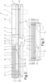
- a machine for the surface processing of products according to the invention is indicated as a whole with the reference number 10. It is inserted in a processing line indicated with 100. More in particular, in this example the line is a line for the surface processing of slabs L made of stone, such as marble, granite and the like, or of glass, wood, ceramic, metal etc. The line is well known, with the exception of the part relating to the processing machine 10.
- the lines 1 comprises, in succession, a rotating storage space 101 for slabs L, an automatic loader 102 taking the slabs L from the storage space 101 and putting them on a comb-shaped loading conveyor table 103 transferring the slabs L onto a first pantograph lifting device 104.
- This latter allows arranging the slabs at the level where they can enter the processing machine 10 of the invention, described below.
- a second pantograph lifting device 105 is provided, bringing the slabs to the level of a comb-shaped unloading conveyor table 106, after which an automatic unloader 107 and a further rotating storage space 108 for slabs L are provided.
- a support L1 for a slab L is provided, in the form of a mainly flat metal frame comprising poles and crossbars, onto which the slab is fastened in a flat fashion.
- a corresponding support L1 is provided for moving the slab inside the processing machine 10.
- the set of support L1 and slab L arriving from the machine 10 onto the second pantograph lifting device 105 is separated, wherein the slab is put on the comb-shaped unloading conveyor table 106 and the support L1 returns to the comb-shaped loading conveyor table 103 through a pair of movable belts 107 provided below the machine 10.
- a number of supports L1 is provided at least equal to the number of slabs to be processed in the processing machine 10, as it will be better explained below.
- the number of supports is equal to the number of slabs to be treated in the machine 10 plus four.
- the surface processing machine 10 comprises a casing 11, internally defining two consecutive sealed chambers, respectively a first sealed chamber 12 and a second sealed chamber 13, separated through an intermediate room 14.
- the first sealed chamber 12 comprises an entrance first opening 15 for a support L1 (bearing a first slab L; here below this set will be referred to as "support-slab L") entering the machine 10.
- the second sealed chamber 13 comprises an exit second opening 16 for a support-slab L.
- Respective sealing doors that can be opened and closed, are associated with these openings.
- the room 14, arranged between the two chambers 12 and 13, has two passages 18 for accessing the two chambers.
- a plan moving device 19 i.e. a device for moving longitudinally, i.e. from the right to the left and in reverse, such as a horizontal moving (where movements according to a more or less inclined direction are even possible) is realized for example through a chain conveyor (defined by two lateral chains spaced from each other) arranged in the machine 10 and extending according to a rectilinear direction from the first opening 15 to the second opening 16 and vice versa, passing through the passages 18 of the intermediate room 14, i.e. crossing this room.
- the plan moving device 19 practically defines a moving plane 19A for the support-slab L, aligned with, i.e. crossing, the openings 15 and 16 and the passages 18.
- a respective moving device 20 is provided for moving, from the bottom upwards and in reverse, i.e. in this example in substantially vertical direction, the supports-slabs L entering the respective chamber, in order to accumulate the supports-slabs L on levels arranged over one another.
- each vertical moving device 20 comprises a rack defining a plurality of lower resting levels arranged over one another, where the supports-slabs can rest. Through one or more translation actuators 22 the rack translates vertically, lifting in succession the supports-slabs following one another in the respective chamber, resting on the conveyor belt 19.
- the rack comprises two side support flanks, each of which defines rests 23 for the supports-slabs, that are vertically spaced. More in particular, each flank is formed by two horizontally spaced vertical uprights 24, along which the rests 23 project.
- the vertical uprights 24 are outside the conveyor belt 19, so that the rests 23 d not interfere with the conveyor belt 19 (see Figs. 3 and 4 ). Furthermore, the supports-slabs L are wider than the conveyor belt 19, thus allowing the rests 23 abutting below the side edges of the same supports-slabs L.
- the translation actuators 22 can be for example four worm actuators, the movable sliders of which are integral with the respective vertical uprights 24.
- the worms of the actuators are connected to a gear motor actuation system 25 provided with pinions and wheels with threaded bar.
- the intermediate room 14 is a room where the surface processing is performed (at a pressure lower than the ambient pressure, i.e. under depressurized or vacuum conditions, i.e. A pressure value approximately equal to zero) and where a surface processing device 26 (preferably arranged on the top of the room 14) works, for example a resin applying device, a painting device or a plasma processing device.
- a surface processing device 26 arranged on the top of the room 14 may be, for example, a vacuum painting device or a vacuum finishing applying device.
- the nozzle of the device deposits the material onto the slab L passing through the room 14 (through the passages 18) from the first chamber 12 t the second chamber 13 and/or vice versa (one or more times).
- the machine also comprises a known device 30 for reducing the pressure in the at least one chamber, which is part of an air suction system, not illustrated in the figures for the sake of simplicity.
- the slabs L borne by the support L1, enter one by one the first sealed chamber 12 through the first opening 15, with the aid of the conveyor belt 19.
- the moving device 20 has the vertical uprights 24 completely lowered, so that the first rests 23' of the vertical uprights 24, i.e. the ones arranged at the top, are at the same level as the support-slab moving plane 19A, i.e. below the supports-slabs ( Fig. 4a ).
- the vertical moving device 20 is actuated and the vertical uprights 24 are lifted up to bring the second subsequent rests 23", that are at a lower level relative to the first rests 23', up to the support-slab moving plane 19A.
- the first slab L' is lifted with respect to this moving plane by a distance greater than the thickness of the set support-slab ( Fig. 4b ).
- a second slab L" enters the first chamber 12 and stops in correspondence of the rack of the vertical moving device 20 (i.e. below the first slab L', which is above the second slab).
- the moving device 20 is actuated and the second slab L" (i.e. the set support-slab), supported by the subsequent second rests 23", is translated upwards.
- the first slab L' is translated upwards.
- Subsequent third rests 23" of the vertical uprights 24 are at the same level as the support-slab moving plane, so as to receive a new support-slab ( Fig. 4d ).
- This procedure goes on based on how many levels or overlapping positions N have been provided for the machine.
- three levels are provided, arranged over one another, defined by three sets of rests 23.
- the last slab L IV inserted into the first chamber 12 remains on the conveyor belt 19 ( figure 3 ).
- the sealing doors 17 are closed and the pressure inside the machine (i.e. the pressure in the common ambient formed by the first chamber 12, the second chamber 13 and the room 14, all directly in fluid communication between them through the passages 18) is reduced, through the pressure reducing device 30, up to the desired depressurization value.
- the last slab L IV passes through the room 14. It should be noted the length of the processing room 14, i.e. the dimension corresponding to the moving direction of the slabs in the machine, is lower than the dimensions of the single sealed chambers.
- the surface processing device 26 is actuated and the surface finishing material is thus deposited on the slab.
- the processing can provide for more coats, i.e. when the slab L IV arrives in the second chamber 13 the movement of the conveyor belt 19 is reversed and the slab is brought again in the first chamber for a further finishing. After that, the movement of the conveyor belt 19 is reversed again and the slab returns in the second chamber 13 (if necessary, a third finishing can be also applied). This forwards/backwards movement is performed based on the specific needs.
- the slab L IV For processing the slab L IV , this latter is stopped in the second chamber 13 (the slab L IV is schematized with a broken line in Fig. 2 ), where the respective vertical moving device 20 lifts the slab L IV up to the next level.
- the slab L′′′ is lowered by one level up to the moving plane. From here, the slab moves and is processed in the same manner as the slab L IV up to the second chamber 13, where it is lifted by one level through the respective moving device.
- the invention also provides for the case of a single chamber 112 where the slabs are arranged over one another, without the need of depositing a material onto the slabs, only performing a depressurization processing, where the slabs do not move and statically remain still for the processing time necessary for the depressurization to perform its function, for example for enhancing the infiltration of the epoxy resin in slabs of stone material.
- the only chamber 112 comprises an entrance first opening 115 for a support-slab L, and an exit second opening 116 for a support-slab L.
- the chamber comprises a plan moving device 119, analogous to the device 19, and an analogous moving device 120.
- a pressure adjusting device 130 is obviously provided.
- the slabs are inserted in the same manner as they are inserted in the first chamber 12, as described above.
- the chamber is pressurized up to achieve the desired pressure limit; then it is opened and the slabs exit according to the same logics that, in this case, are obviously LIFO ( Last in -First out ) logics.
- the processing capacity of this room is N+1 (in this example again N is equal to 3).
- the processing machine of the first example i.e. the machine of Figs. 2 to 4
- the number of processable slabs is equal to 2*(N+1), that is 8 slabs in the illustrated example.
- the machine of the invention providing for contemporaneously inserting more products into the processing machine, it is possible the surface processing of products in less time than in the prior art, as at least the time necessary for closing and opening the doors is saved, as well as the time for achieving the working pressure, the time for keeping/processing the slabs under the achieved working pressure, the time for achieving the ambient pressure again.
- the configuration also allows to reduce the overall bulk with respect to the cases where more parallel lines are provided in the plant for performing more processing in parallel.
Landscapes
- Engineering & Computer Science (AREA)
- Mechanical Engineering (AREA)
- Mining & Mineral Resources (AREA)
- Physical Vapour Deposition (AREA)
- Processing Of Stones Or Stones Resemblance Materials (AREA)
- Cleaning By Liquid Or Steam (AREA)
- Treatments Of Macromolecular Shaped Articles (AREA)
- Processing And Handling Of Plastics And Other Materials For Molding In General (AREA)
- Perforating, Stamping-Out Or Severing By Means Other Than Cutting (AREA)
Claims (13)
- Bearbeitungsmaschine für die Oberflächenbearbeitung von Produkten, umfassend:- mindestens eine abgedichtete Kammer (12, 112, 13), die mit mindestens einer verschließbaren Öffnung (15, 16, 115, 116) zum Einlegen und Entnehmen einer Mehrzahl von zu bearbeitenden Produkten (L) bereitgestellt ist,- eine Vorrichtung (30) zum Reduzieren des Drucks innerhalb der mindestens einen Kammer (12, 112, 13) auf einen Wert, der niedriger als der Umgebungsdruck ist,- in der mindestens einen Kammer (12, 112, 13) eine Bewegungsvorrichtung (20), die im Betrieb die Produkte (L) von unten nach oben und umgekehrt bewegt, um in der Kammer mindestens zwei der Produkte (L) auf übereinander angeordneten Ebenen anzusammeln,- eine Planbewegungsvorrichtung (19) zum Bewegen der Produkte von und zu der mindestens einen Öffnung (15, 16, 115, 116), wenn die Produkte auf demselben Niveau wie die mindestens eine Öffnung angeordnet sind,wobei aus betrieblicher Sicht eine Mehrzahl (LI, LII, LIII, LIV) der Produkte in die mindestens eine Kammer (12, 112, 13) eingeführt wird und mindestens zwei Produkte der Mehrzahl von Produkten für eine Bearbeitungsspanne übereinander gelegt werden, und wobei, sobald alle zu bearbeitenden Produkte in die mindestens eine Kammer (12, 112, 13) eingeführt worden sind, die Kammer (12, 112, 13) geschlossen wird und der Druck im Inneren bis zu einem Betriebsbearbeitungsdruck verringert wird, und dann die mindestens eine Kammer (12, 112, 13) wieder geöffnet wird und die Produkte (LI, LII, LIII, LIV) daraus entnommen werden.
- Bearbeitungsmaschine gemäß Anspruch 1, umfassend mindestens zwei der abgedichteten Kammern (12, 13), die miteinander verbunden sind, wobei jede Kammer ausgebildet ist, eine Mehrzahl der übereinander angeordneten Produkte (LI, LII, LIII, LIV) aufzunehmen.
- Bearbeitungsmaschine gemäß Anspruch 2, wobei eine Bearbeitungsvorrichtung (26) zur Oberflächenbearbeitung eines Produkts zwischen den beiden abgedichteten Kammern (12, 13) angeordnet ist.
- Bearbeitungsmaschine gemäß Anspruch 3, wobei zwischen den mindestens zwei Kammern (12, 13) ein Bearbeitungsraum (14) bereitgestellt ist, in dem die Vorrichtung (26) zur Oberflächenbearbeitung so angeordnet ist, dass die Produkte ausgebildet sind, sich von einer Kammer (12) in die folgende (13) zu bewegen, indem sie die Bearbeitung realisierend den Raum (14) passieren.
- Bearbeitungsmaschine gemäß Anspruch 2, 3 oder 4, wobei nur zwei der abgedichteten Kammern (12, 13) hintereinander bereitgestellt sind.
- Bearbeitungsmaschine gemäß Anspruch 3, 4 oder 5, wobei die Planbewegungsvorrichtung (19) dazu ausgebildet ist, die Produkte von einer Kammer (12) in die folgende (13) unterhalb der Bearbeitungsvorrichtung (26) passieren zu lassen.
- Bearbeitungsmaschine gemäß Anspruch 6, wobei die Planbewegungsvorrichtung (19) den Kammern (12, 13) gemeinsam ist; vorzugsweise ist die Planbewegungsvorrichtung (19) ein Förderband, das die Kammern von einer ersten Eingangsöffnung (15) der Maschine bis zu einer zweiten Ausgangsöffnung (16) der Maschine durchquert und unter der Bearbeitungsvorrichtung (26) entlangläuft.
- Bearbeitungsmaschine gemäß einem oder mehreren der vorangehenden Ansprüche, umfassend eine erste Öffnung (15) für die in die Maschine eintretenden Produkte, die in der ersten Kammer (12) definiert ist, und eine zweite Öffnung (16) für die aus der Maschine austretenden Produkte, die in der zweiten Kammer (13) definiert ist, wobei den Öffnungen (15, 16) jeweils zugeordnete Dichtungstüren (17) bereitgestellt sind.
- Bearbeitungsmaschine gemäß Anspruch 2, wobei in jeder Kammer (12, 13) eine Vorrichtung (20) zum Bewegen der Produkte von unten nach oben bereitgestellt wird, um mindestens zwei der Produkte (LI, LII, LIII, LIV) auf übereinander angeordneten Ebenen anzusammeln.
- Bearbeitungsmaschine gemäß Anspruch 3, wobei in den mindestens zwei Kammern (12, 13) eine Bewegungsebene zum Bewegen der Produkte vom Eingang zum Ausgang der Maschine definiert ist, die die Kammern durchquert und unterhalb der Bearbeitungsvorrichtung (26) verläuft, wobei jede Bewegungsvorrichtung (20) von unten nach oben N Positionen definiert, die von der Bewegungsebene erhöht sind, und wobei die maximale Anzahl von Produkten, die in der Maschine bearbeitet werden können, N+1 beträgt.
- Bearbeitungsmaschine gemäß einem oder mehreren der Ansprüche 2 bis 10, wobei die Bearbeitungsvorrichtung (20) eine Vakuum-Lackiervorrichtung, eine Vakuum-Plasmabearbeitungsvorrichtung oder eine Harzauftragsvorrichtung ist.
- Bearbeitungsmaschine gemäß einem oder mehreren der vorangehenden Ansprüche, wobei jedes Produkt von einem jeweiligen Träger (L1) getragen wird, sodass die Produkte auf den Trägern (L1) in die Maschine eintreten und diese verlassen, und wobei die Bewegungsvorrichtung (20) und die Planbewegungsvorrichtung (19) ausgebildet sind, die Produkte durch direkte Bewegung der Träger (L1) zu bewegen.
- Bearbeitungsmaschine gemäß einem oder mehreren der vorangehenden Ansprüche, wobei jedes Produkt (L) eine Form einer Platte aufweist, die vorzugsweise aus Stein, Glas, Holz, Keramik oder Metall besteht.
Applications Claiming Priority (2)
| Application Number | Priority Date | Filing Date | Title |
|---|---|---|---|
| IT201900010422 | 2019-06-28 | ||
| PCT/IB2020/056016 WO2020261172A1 (en) | 2019-06-28 | 2020-06-25 | Machine for the surface processing of products |
Publications (2)
| Publication Number | Publication Date |
|---|---|
| EP3990194A1 EP3990194A1 (de) | 2022-05-04 |
| EP3990194B1 true EP3990194B1 (de) | 2023-08-09 |
Family
ID=68343306
Family Applications (1)
| Application Number | Title | Priority Date | Filing Date |
|---|---|---|---|
| EP20740724.8A Active EP3990194B1 (de) | 2019-06-28 | 2020-06-25 | Anlage zur oberflächenbearbeitung von produkten |
Country Status (7)
| Country | Link |
|---|---|
| US (1) | US11845094B2 (de) |
| EP (1) | EP3990194B1 (de) |
| BR (1) | BR112021026540A2 (de) |
| CA (1) | CA3145367A1 (de) |
| ES (1) | ES2961938T3 (de) |
| PT (1) | PT3990194T (de) |
| WO (1) | WO2020261172A1 (de) |
Family Cites Families (4)
| Publication number | Priority date | Publication date | Assignee | Title |
|---|---|---|---|---|
| ITTO20030459A1 (it) * | 2003-06-18 | 2004-12-19 | Taltos Srl | Procedimento per realizzare pannelli decorativi di materiale lapideo o simile. |
| DE102008026314B4 (de) * | 2008-05-31 | 2010-07-22 | Roth & Rau Ag | Vakuumanlage mit mindestens zwei Vakuumkammern und einer Schleusenkammer zwischen den Vakuumkammern |
| CN102343627B (zh) * | 2011-10-18 | 2015-01-28 | 刘建平 | 多层组合型真空石材成型装置 |
| CN110049825B (zh) | 2016-10-20 | 2021-11-05 | 普罗默特克有限责任公司 | 用于将流体物质施加到石材上的工位 |
-
2020
- 2020-06-25 EP EP20740724.8A patent/EP3990194B1/de active Active
- 2020-06-25 PT PT207407248T patent/PT3990194T/pt unknown
- 2020-06-25 BR BR112021026540A patent/BR112021026540A2/pt not_active Application Discontinuation
- 2020-06-25 ES ES20740724T patent/ES2961938T3/es active Active
- 2020-06-25 WO PCT/IB2020/056016 patent/WO2020261172A1/en not_active Ceased
- 2020-06-25 US US17/623,164 patent/US11845094B2/en active Active
- 2020-06-25 CA CA3145367A patent/CA3145367A1/en active Pending
Also Published As
| Publication number | Publication date |
|---|---|
| EP3990194A1 (de) | 2022-05-04 |
| CA3145367A1 (en) | 2020-12-30 |
| BR112021026540A2 (pt) | 2022-05-17 |
| US11845094B2 (en) | 2023-12-19 |
| US20220355326A1 (en) | 2022-11-10 |
| ES2961938T3 (es) | 2024-03-14 |
| PT3990194T (pt) | 2023-10-30 |
| WO2020261172A1 (en) | 2020-12-30 |
Similar Documents
| Publication | Publication Date | Title |
|---|---|---|
| CA2185898C (en) | Car body surface treatment device | |
| KR102343623B1 (ko) | 객체의 표면 처리를 위한 스테이션 및 플랜트 | |
| RU2009136423A (ru) | Вакуумная установка для нанесения покрытий | |
| EP1507894B1 (de) | Beschichtungsvorrichtung mit transporteinrichtung | |
| DE102009004493B3 (de) | Vakuumbeschichtungsanlage und Verfahren zum Betrieb einer Vakuumbeschichtungsanlage | |
| US20130199893A1 (en) | Conveyor unit and conveyor system for conveying vehicle bodies and plant for machining vehicle bodies | |
| CH691376A5 (de) | Vakuumanlage zur Oberflächenbearbeitung von Werkstücken. | |
| DE102011078707A1 (de) | Fördervorrichtung | |
| CA1321565C (en) | Intermittent work conveying apparatus | |
| US20140173928A1 (en) | Method and apparatus for drying workpieces | |
| ITMI20112090A1 (it) | Impianto rapido per il trattamento ad immersione di scocche | |
| US11845094B2 (en) | Machine for the surface processing of products | |
| US4287144A (en) | Method of manufacturing cementitious articles and various forms of equipment of putting this method into practice | |
| EP4088929B1 (de) | Anlage zur bearbeitung von keramik- oder steinplatten | |
| CN209871522U (zh) | 抽油杆自动喷涂打包生产线 | |
| DE102008011774A1 (de) | Schleusenvorrichtung zum Ein- und Ausbringen von Behältern in und aus einer Vakuumbehandlungskammer | |
| KR102549106B1 (ko) | 자동화 도장설비 | |
| CN113385433A (zh) | 用于对板件组进行选择性分拣的设备和方法 | |
| KR20100075721A (ko) | 도장 공정과 연계 가능한 인라인 진공증착 시스템 및 이를 이용한 증착 방법 | |
| WO2022034620A1 (en) | A resin line machine for curing resin on natural stone and method thereof | |
| DE102008026314B4 (de) | Vakuumanlage mit mindestens zwei Vakuumkammern und einer Schleusenkammer zwischen den Vakuumkammern | |
| EP3927513B1 (de) | Verharzungsanlage für platten aus steinmaterial und verfahren zur verharzung von platten aus steinmaterial | |
| CZ7381U1 (cs) | Zařízení pro postřikování polotovarů krytinových tašek | |
| JP2818558B2 (ja) | 成形品処理装置における開閉扉装置 | |
| ITUD20010035A1 (it) | Dispositivo di carico-scarico di articoli fra due stazioni di lavoro e relativo procedimento |
Legal Events
| Date | Code | Title | Description |
|---|---|---|---|
| STAA | Information on the status of an ep patent application or granted ep patent |
Free format text: STATUS: UNKNOWN |
|
| STAA | Information on the status of an ep patent application or granted ep patent |
Free format text: STATUS: THE INTERNATIONAL PUBLICATION HAS BEEN MADE |
|
| PUAI | Public reference made under article 153(3) epc to a published international application that has entered the european phase |
Free format text: ORIGINAL CODE: 0009012 |
|
| STAA | Information on the status of an ep patent application or granted ep patent |
Free format text: STATUS: REQUEST FOR EXAMINATION WAS MADE |
|
| 17P | Request for examination filed |
Effective date: 20211221 |
|
| AK | Designated contracting states |
Kind code of ref document: A1 Designated state(s): AL AT BE BG CH CY CZ DE DK EE ES FI FR GB GR HR HU IE IS IT LI LT LU LV MC MK MT NL NO PL PT RO RS SE SI SK SM TR |
|
| DAV | Request for validation of the european patent (deleted) | ||
| DAX | Request for extension of the european patent (deleted) | ||
| GRAP | Despatch of communication of intention to grant a patent |
Free format text: ORIGINAL CODE: EPIDOSNIGR1 |
|
| STAA | Information on the status of an ep patent application or granted ep patent |
Free format text: STATUS: GRANT OF PATENT IS INTENDED |
|
| RIC1 | Information provided on ipc code assigned before grant |
Ipc: B65G 47/51 20060101ALN20230124BHEP Ipc: B28D 1/00 20060101ALI20230124BHEP Ipc: B05B 16/00 20180101ALI20230124BHEP Ipc: B05B 13/02 20060101AFI20230124BHEP |
|
| INTG | Intention to grant announced |
Effective date: 20230301 |
|
| GRAS | Grant fee paid |
Free format text: ORIGINAL CODE: EPIDOSNIGR3 |
|
| GRAA | (expected) grant |
Free format text: ORIGINAL CODE: 0009210 |
|
| STAA | Information on the status of an ep patent application or granted ep patent |
Free format text: STATUS: THE PATENT HAS BEEN GRANTED |
|
| AK | Designated contracting states |
Kind code of ref document: B1 Designated state(s): AL AT BE BG CH CY CZ DE DK EE ES FI FR GB GR HR HU IE IS IT LI LT LU LV MC MK MT NL NO PL PT RO RS SE SI SK SM TR |
|
| REG | Reference to a national code |
Ref country code: GB Ref legal event code: FG4D |
|
| REG | Reference to a national code |
Ref country code: CH Ref legal event code: EP |
|
| REG | Reference to a national code |
Ref country code: IE Ref legal event code: FG4D |
|
| REG | Reference to a national code |
Ref country code: DE Ref legal event code: R096 Ref document number: 602020015501 Country of ref document: DE |
|
| REG | Reference to a national code |
Ref country code: PT Ref legal event code: SC4A Ref document number: 3990194 Country of ref document: PT Date of ref document: 20231030 Kind code of ref document: T Free format text: AVAILABILITY OF NATIONAL TRANSLATION Effective date: 20231023 |
|
| REG | Reference to a national code |
Ref country code: LT Ref legal event code: MG9D |
|
| REG | Reference to a national code |
Ref country code: NL Ref legal event code: MP Effective date: 20230809 |
|
| REG | Reference to a national code |
Ref country code: GR Ref legal event code: EP Ref document number: 20230402078 Country of ref document: GR Effective date: 20231211 |
|
| REG | Reference to a national code |
Ref country code: AT Ref legal event code: MK05 Ref document number: 1596878 Country of ref document: AT Kind code of ref document: T Effective date: 20230809 |
|
| PG25 | Lapsed in a contracting state [announced via postgrant information from national office to epo] |
Ref country code: IS Free format text: LAPSE BECAUSE OF FAILURE TO SUBMIT A TRANSLATION OF THE DESCRIPTION OR TO PAY THE FEE WITHIN THE PRESCRIBED TIME-LIMIT Effective date: 20231209 |
|
| PG25 | Lapsed in a contracting state [announced via postgrant information from national office to epo] |
Ref country code: SE Free format text: LAPSE BECAUSE OF FAILURE TO SUBMIT A TRANSLATION OF THE DESCRIPTION OR TO PAY THE FEE WITHIN THE PRESCRIBED TIME-LIMIT Effective date: 20230809 Ref country code: RS Free format text: LAPSE BECAUSE OF FAILURE TO SUBMIT A TRANSLATION OF THE DESCRIPTION OR TO PAY THE FEE WITHIN THE PRESCRIBED TIME-LIMIT Effective date: 20230809 Ref country code: NO Free format text: LAPSE BECAUSE OF FAILURE TO SUBMIT A TRANSLATION OF THE DESCRIPTION OR TO PAY THE FEE WITHIN THE PRESCRIBED TIME-LIMIT Effective date: 20231109 Ref country code: NL Free format text: LAPSE BECAUSE OF FAILURE TO SUBMIT A TRANSLATION OF THE DESCRIPTION OR TO PAY THE FEE WITHIN THE PRESCRIBED TIME-LIMIT Effective date: 20230809 Ref country code: LV Free format text: LAPSE BECAUSE OF FAILURE TO SUBMIT A TRANSLATION OF THE DESCRIPTION OR TO PAY THE FEE WITHIN THE PRESCRIBED TIME-LIMIT Effective date: 20230809 Ref country code: LT Free format text: LAPSE BECAUSE OF FAILURE TO SUBMIT A TRANSLATION OF THE DESCRIPTION OR TO PAY THE FEE WITHIN THE PRESCRIBED TIME-LIMIT Effective date: 20230809 Ref country code: IS Free format text: LAPSE BECAUSE OF FAILURE TO SUBMIT A TRANSLATION OF THE DESCRIPTION OR TO PAY THE FEE WITHIN THE PRESCRIBED TIME-LIMIT Effective date: 20231209 Ref country code: HR Free format text: LAPSE BECAUSE OF FAILURE TO SUBMIT A TRANSLATION OF THE DESCRIPTION OR TO PAY THE FEE WITHIN THE PRESCRIBED TIME-LIMIT Effective date: 20230809 Ref country code: FI Free format text: LAPSE BECAUSE OF FAILURE TO SUBMIT A TRANSLATION OF THE DESCRIPTION OR TO PAY THE FEE WITHIN THE PRESCRIBED TIME-LIMIT Effective date: 20230809 Ref country code: AT Free format text: LAPSE BECAUSE OF FAILURE TO SUBMIT A TRANSLATION OF THE DESCRIPTION OR TO PAY THE FEE WITHIN THE PRESCRIBED TIME-LIMIT Effective date: 20230809 |
|
| PG25 | Lapsed in a contracting state [announced via postgrant information from national office to epo] |
Ref country code: PL Free format text: LAPSE BECAUSE OF FAILURE TO SUBMIT A TRANSLATION OF THE DESCRIPTION OR TO PAY THE FEE WITHIN THE PRESCRIBED TIME-LIMIT Effective date: 20230809 |
|
| REG | Reference to a national code |
Ref country code: ES Ref legal event code: FG2A Ref document number: 2961938 Country of ref document: ES Kind code of ref document: T3 Effective date: 20240314 |
|
| PG25 | Lapsed in a contracting state [announced via postgrant information from national office to epo] |
Ref country code: SM Free format text: LAPSE BECAUSE OF FAILURE TO SUBMIT A TRANSLATION OF THE DESCRIPTION OR TO PAY THE FEE WITHIN THE PRESCRIBED TIME-LIMIT Effective date: 20230809 Ref country code: RO Free format text: LAPSE BECAUSE OF FAILURE TO SUBMIT A TRANSLATION OF THE DESCRIPTION OR TO PAY THE FEE WITHIN THE PRESCRIBED TIME-LIMIT Effective date: 20230809 Ref country code: EE Free format text: LAPSE BECAUSE OF FAILURE TO SUBMIT A TRANSLATION OF THE DESCRIPTION OR TO PAY THE FEE WITHIN THE PRESCRIBED TIME-LIMIT Effective date: 20230809 Ref country code: DK Free format text: LAPSE BECAUSE OF FAILURE TO SUBMIT A TRANSLATION OF THE DESCRIPTION OR TO PAY THE FEE WITHIN THE PRESCRIBED TIME-LIMIT Effective date: 20230809 Ref country code: CZ Free format text: LAPSE BECAUSE OF FAILURE TO SUBMIT A TRANSLATION OF THE DESCRIPTION OR TO PAY THE FEE WITHIN THE PRESCRIBED TIME-LIMIT Effective date: 20230809 Ref country code: SK Free format text: LAPSE BECAUSE OF FAILURE TO SUBMIT A TRANSLATION OF THE DESCRIPTION OR TO PAY THE FEE WITHIN THE PRESCRIBED TIME-LIMIT Effective date: 20230809 |
|
| REG | Reference to a national code |
Ref country code: DE Ref legal event code: R097 Ref document number: 602020015501 Country of ref document: DE |
|
| PLBE | No opposition filed within time limit |
Free format text: ORIGINAL CODE: 0009261 |
|
| STAA | Information on the status of an ep patent application or granted ep patent |
Free format text: STATUS: NO OPPOSITION FILED WITHIN TIME LIMIT |
|
| 26N | No opposition filed |
Effective date: 20240513 |
|
| PG25 | Lapsed in a contracting state [announced via postgrant information from national office to epo] |
Ref country code: SI Free format text: LAPSE BECAUSE OF FAILURE TO SUBMIT A TRANSLATION OF THE DESCRIPTION OR TO PAY THE FEE WITHIN THE PRESCRIBED TIME-LIMIT Effective date: 20230809 |
|
| PG25 | Lapsed in a contracting state [announced via postgrant information from national office to epo] |
Ref country code: BG Free format text: LAPSE BECAUSE OF FAILURE TO SUBMIT A TRANSLATION OF THE DESCRIPTION OR TO PAY THE FEE WITHIN THE PRESCRIBED TIME-LIMIT Effective date: 20230809 |
|
| PG25 | Lapsed in a contracting state [announced via postgrant information from national office to epo] |
Ref country code: BG Free format text: LAPSE BECAUSE OF FAILURE TO SUBMIT A TRANSLATION OF THE DESCRIPTION OR TO PAY THE FEE WITHIN THE PRESCRIBED TIME-LIMIT Effective date: 20230809 |
|
| REG | Reference to a national code |
Ref country code: DE Ref legal event code: R119 Ref document number: 602020015501 Country of ref document: DE |
|
| PG25 | Lapsed in a contracting state [announced via postgrant information from national office to epo] |
Ref country code: MC Free format text: LAPSE BECAUSE OF FAILURE TO SUBMIT A TRANSLATION OF THE DESCRIPTION OR TO PAY THE FEE WITHIN THE PRESCRIBED TIME-LIMIT Effective date: 20230809 |
|
| REG | Reference to a national code |
Ref country code: CH Ref legal event code: PL |
|
| PG25 | Lapsed in a contracting state [announced via postgrant information from national office to epo] |
Ref country code: LU Free format text: LAPSE BECAUSE OF NON-PAYMENT OF DUE FEES Effective date: 20240625 |
|
| GBPC | Gb: european patent ceased through non-payment of renewal fee |
Effective date: 20240625 |
|
| PG25 | Lapsed in a contracting state [announced via postgrant information from national office to epo] |
Ref country code: PT Free format text: LAPSE BECAUSE OF NON-PAYMENT OF DUE FEES Effective date: 20250325 Ref country code: DE Free format text: LAPSE BECAUSE OF NON-PAYMENT OF DUE FEES Effective date: 20250101 |
|
| PG25 | Lapsed in a contracting state [announced via postgrant information from national office to epo] |
Ref country code: IE Free format text: LAPSE BECAUSE OF NON-PAYMENT OF DUE FEES Effective date: 20240625 |
|
| PG25 | Lapsed in a contracting state [announced via postgrant information from national office to epo] |
Ref country code: CH Free format text: LAPSE BECAUSE OF NON-PAYMENT OF DUE FEES Effective date: 20240630 Ref country code: BE Free format text: LAPSE BECAUSE OF NON-PAYMENT OF DUE FEES Effective date: 20240630 Ref country code: GR Free format text: LAPSE BECAUSE OF NON-PAYMENT OF DUE FEES Effective date: 20250108 |
|
| PG25 | Lapsed in a contracting state [announced via postgrant information from national office to epo] |
Ref country code: FR Free format text: LAPSE BECAUSE OF NON-PAYMENT OF DUE FEES Effective date: 20240630 |
|
| PG25 | Lapsed in a contracting state [announced via postgrant information from national office to epo] |
Ref country code: IT Free format text: LAPSE BECAUSE OF NON-PAYMENT OF DUE FEES Effective date: 20240625 Ref country code: GB Free format text: LAPSE BECAUSE OF NON-PAYMENT OF DUE FEES Effective date: 20240625 |
|
| REG | Reference to a national code |
Ref country code: BE Ref legal event code: MM Effective date: 20240630 |
|
| REG | Reference to a national code |
Ref country code: ES Ref legal event code: FD2A Effective date: 20250728 |
|
| PG25 | Lapsed in a contracting state [announced via postgrant information from national office to epo] |
Ref country code: ES Free format text: LAPSE BECAUSE OF NON-PAYMENT OF DUE FEES Effective date: 20240626 |
|
| PG25 | Lapsed in a contracting state [announced via postgrant information from national office to epo] |
Ref country code: CY Free format text: LAPSE BECAUSE OF FAILURE TO SUBMIT A TRANSLATION OF THE DESCRIPTION OR TO PAY THE FEE WITHIN THE PRESCRIBED TIME-LIMIT; INVALID AB INITIO Effective date: 20200625 |
|
| PG25 | Lapsed in a contracting state [announced via postgrant information from national office to epo] |
Ref country code: HU Free format text: LAPSE BECAUSE OF FAILURE TO SUBMIT A TRANSLATION OF THE DESCRIPTION OR TO PAY THE FEE WITHIN THE PRESCRIBED TIME-LIMIT; INVALID AB INITIO Effective date: 20200625 |