EP4087772B1 - Transport trailer comprising a system for tilting and righting its deck - Google Patents
Transport trailer comprising a system for tilting and righting its deck Download PDFInfo
- Publication number
- EP4087772B1 EP4087772B1 EP21704602.8A EP21704602A EP4087772B1 EP 4087772 B1 EP4087772 B1 EP 4087772B1 EP 21704602 A EP21704602 A EP 21704602A EP 4087772 B1 EP4087772 B1 EP 4087772B1
- Authority
- EP
- European Patent Office
- Prior art keywords
- trailer
- draw bar
- deck
- wheels
- pivot connection
- Prior art date
- Legal status (The legal status is an assumption and is not a legal conclusion. Google has not performed a legal analysis and makes no representation as to the accuracy of the status listed.)
- Active
Links
- 238000005096 rolling process Methods 0.000 claims description 43
- 238000000034 method Methods 0.000 claims description 11
- 239000000463 material Substances 0.000 claims description 10
- 238000006243 chemical reaction Methods 0.000 claims description 8
- 239000002184 metal Substances 0.000 claims description 3
- 230000003100 immobilizing effect Effects 0.000 claims 5
- 241000946381 Timon Species 0.000 description 11
- 230000008878 coupling Effects 0.000 description 7
- 238000010168 coupling process Methods 0.000 description 7
- 238000005859 coupling reaction Methods 0.000 description 7
- 230000000903 blocking effect Effects 0.000 description 6
- 238000004804 winding Methods 0.000 description 4
- 238000003825 pressing Methods 0.000 description 3
- 238000011084 recovery Methods 0.000 description 3
- 229910000831 Steel Inorganic materials 0.000 description 2
- 240000008042 Zea mays Species 0.000 description 2
- 239000006096 absorbing agent Substances 0.000 description 2
- 230000008901 benefit Effects 0.000 description 2
- 229940082150 encore Drugs 0.000 description 2
- 230000005484 gravity Effects 0.000 description 2
- 230000035939 shock Effects 0.000 description 2
- 239000010959 steel Substances 0.000 description 2
- 230000009471 action Effects 0.000 description 1
- 238000013459 approach Methods 0.000 description 1
- 230000003416 augmentation Effects 0.000 description 1
- 230000007423 decrease Effects 0.000 description 1
- 230000003247 decreasing effect Effects 0.000 description 1
- 230000000694 effects Effects 0.000 description 1
- 230000007246 mechanism Effects 0.000 description 1
- 230000004048 modification Effects 0.000 description 1
- 238000012986 modification Methods 0.000 description 1
- 230000002093 peripheral effect Effects 0.000 description 1
- 230000009467 reduction Effects 0.000 description 1
- 230000000284 resting effect Effects 0.000 description 1
Images


Classifications
-
- B—PERFORMING OPERATIONS; TRANSPORTING
- B62—LAND VEHICLES FOR TRAVELLING OTHERWISE THAN ON RAILS
- B62D—MOTOR VEHICLES; TRAILERS
- B62D63/00—Motor vehicles or trailers not otherwise provided for
- B62D63/06—Trailers
- B62D63/061—Foldable, extensible or yielding trailers
-
- B—PERFORMING OPERATIONS; TRANSPORTING
- B62—LAND VEHICLES FOR TRAVELLING OTHERWISE THAN ON RAILS
- B62D—MOTOR VEHICLES; TRAILERS
- B62D63/00—Motor vehicles or trailers not otherwise provided for
- B62D63/06—Trailers
- B62D63/062—Trailers with one axle or two wheels
Definitions
- the invention relates to a transport trailer that can be tilted and adapted to be straightened, and more particularly to an open trailer of the platform type enabling a user to load and unload heavy and/or bulky objects on a platform by himself of the trailer and also capable of being stored in the upright position.
- open trailers are commonly used to transport objects and/or materials that are too bulky to fit into a closed vehicle, which could dirty such a closed vehicle, or even to increase the transport capacity of a towing vehicle.
- Such an open trailer may optionally be, for the purposes of a given use, closed or partially closed using a tarpaulin or any removable structure, and then reopened for another use.
- Trailers generally comprise a platform arranged for rolling substantially parallel to the ground and on which the objects and/or materials to be transported are placed.
- the trays of the trailers are arranged at a certain distance from the ground, making it difficult to load and unload heavy and/or bulky objects and/or materials.
- a trailer comprising a tilting platform towards the rear of the trailer so that the rear of the platform is, in the loading or unloading phase, at the contact with the ground in order to define a slope with respect to the ground.
- a trailer described in this document comprises a winch fixed to a frame and a cable connected to an axle of the trailer.
- the axis of the wheels being offset with respect to the axis of the axle, the winch is able, by unwinding the cable, to make the axle pivot with respect to the plate, which causes the lowering of the axis of the axle in relation to the axis of the wheels allowing the inclination of the platform in relation to the ground to be increased until it comes into contact with the rear of the tray with the floor.
- the platform thus defines a slope facilitating the loading and unloading of the trailer.
- the winch is able, by winding the cable, to cause the axle to pivot relative to the plate, which causes the axle axis to be raised by with respect to the axis of the wheels making it possible to reduce the inclination of the plate relative to the ground until the plate is substantially parallel to the ground.
- an open trailer generally having a large floor area compared to its height, occupies, when it is in the rolling position and is not used but on the contrary stored for example in a garage, a large floor area. and an empty volume above the trailer that is difficult or even impossible to use.
- the trailer described in the document WO 2019/162433 A1 is also adept at adopting an upright position.
- the platform of the trailer described in this document in addition to the fact that it is tiltable, consists of a front part and a rear part articulated via a folding axis substantially parallel to the axle.
- the folding axis is arranged so that the rear part is foldable on the front part of the platform and so that the wheels of the trailer project beyond the rear of said folding axis of the platform.
- the empty trailer can thus be straightened by raising its drawbar so as to cause the two parts of the platform to pivot on the wheels until the folded platform is arranged substantially perpendicular to the ground.
- the trailer further includes a fold-out kickstand to hold the folded trailer in an upright position.
- the document WO 2008/147207 A1 describes a trailer comprising a drawbar articulated to the platform via a folding axis.
- the trailer also includes a winch mounted on a middle part of the drawbar and a cable whose ends are fixed to the winch and to a central part of the board.
- the drawbar and the platform of the trailer are arranged substantially parallel to the ground.
- the trailer straightens by resting on a rear part of the platform and on a wheel arranged at the level of the hitching head of the trailer, which causes the approximation of the drawbar towards the platform by pivoting around said folding axis.
- the object of the invention is to provide a trailer comprising a tilting platform in order to facilitate the loading and unloading of the trailer and able to be placed in an upright position, reducing the size of the trailer when it is not not used, requiring the user as little as possible.
- a trailer comprising a frame, a plate fixed to the frame, the plate being intended to support objects and/or materials to be transported, wheels fixed to the frame, the wheels being intended to rest on the ground, a drawbar in pivot connection with the frame, the pivot connection being substantially parallel to the axes of the wheels and allowing the folding of the drawbar against the lower surface of the plate.
- the drawbar projects from the platform in a direction substantially perpendicular to the axles of the wheels, the trailer further comprising a means for locking the pivot connection and a conversion system comprising a traction means, for example a non-elastic flexible slender element integral of the plate and a device for adjusting the length of said element, the length of said element defining the distance of at least part of the plate relative to the ground by pivoting of the plate around a pivot link for loading and unloading parallel to the axes of the wheels.
- a traction means for example a non-elastic flexible slender element integral of the plate and a device for adjusting the length of said element, the length of said element defining the distance of at least part of the plate relative to the ground by pivoting of the plate around a pivot link for loading and unloading parallel to the axes of the wheels.
- the trailer is also able to be placed in a straightened position in which the platform is substantially perpendicular to the ground.
- Such a trailer thus makes it possible to lower the platform of the trailer to facilitate the loading and unloading of the latter.
- Such a trailer also makes it possible to reduce its size when not in use by positioning it in the upright position.
- the device for adjusting the length of the flexible slender element or more generally, the device for controlling the traction element is fixed to the drawbar, or mounted on the drawbar.
- the device for controlling the traction element is fixed to the drawbar, or mounted on the drawbar.
- the conversion device makes it possible, in addition to converting the trailer between the rolling and lowered positions, to convert the trailer to the upright position.
- This last conversion requires very little user and allows the design of a simple trailer in which a single conversion device can pass, minimizing the efforts between three different positions.
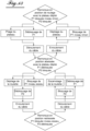
- a method of converting a trailer between a rolling position in which the wheels of the trailer rest on the ground, a lowered position in which at least a part of a bed of the trailer is closer to the ground than in the rolling position, the tray being intended to support objects and/or materials to be transported, and an upright position in which the tray is substantially perpendicular to the ground comprising, to convert the trailer between the rolling position and the lowered position, a variation of a length of a flexible elongate element of the trailer, the method comprising, to convert the trailer between the rolling and the lowered position, blocking of a pivot connection of a drawbar of the trailer with a frame of the trailer, the plate being integral with the frame and the drawbar extending in a direction substantially perpendicular to said pivot connection, and in that it comprises, to convert the trailer to the upright position, an unlocking of said pivot connection and a modification of the length of the flexible slender element.
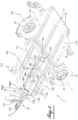
- THE figures 1 to 11 represent a trailer 1 comprising a substantially rectangular platform 11, a single set of wheels comprising two coaxial wheels 12 mounted on either side of the platform 11 along the long sides thereof and a drawbar 15 projecting from the plate 11 in the middle of a short side of the plate 11 defining the front of the trailer 1.
- the drawbar 15 comprises a coupling head 151 allowing the trailer 1 to be moved, for example by fixing this head 151 to coupling to a towing vehicle.
- the wheels 12 are arranged so as to be capable of rotating around an axis P3 perpendicular to the horizontal direction defined by the drawbar 15.
- the tray 11 is intended to receive objects and/or materials in order to transport them.
- the plate 11 comprises a peripheral frame 111 and a floor 112, preferably made of sheet metal.
- the trailer 1 is able to transport two motorcycles.
- the trailer 1 comprises on its plate 11 two supports 113 each intended to block the front wheel of a motorcycle placed on the trailer 1.
- the trailer 1 also comprises attachment means 114 making it possible to strap the motorcycles or any other object placed on the trailer 1.
- the trailer 1 comprises a jockey wheel 16 secured to the drawbar 15.
- the jockey wheel 16 can take two positions: a deployed position so as to support the drawbar 15 by pressing on the ground S when necessary, in particular when the trailer is not not attached to a towing vehicle, and a retracted position so as not to interfere with the maneuvering of the trailer when driving.
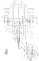
- the trailer 1 comprises two arms 13 each connecting the hub of one of the wheels 12 to an axle 14 fixed under the plate 11.
- the axle 14 receives at each end the arms 13 to which the wheels 12.
- the arms 13 are each arranged in a vertical plane parallel to the drawbar 15.
- the arms 13 offset the axis P3 of rotation of the wheels 12 with respect to an axis defined by the axle 14.
- the axle 14 is mounted in pivot connection P1 with a horizontal axis with the plate 11 of the trailer 1.
- Trailer 1 also includes a tilt and straighten system.
- Said system comprises a winch 171 mounted on the drawbar 15, beyond the limit of the platform, and a lever 172, one end of which is fixed by fitting to the axle 14 at about half its length, under the platform.
- the inclination and recovery system further comprises a cable 173, metal (steel, for example) connecting, under the front of the plate, the winch 171, on which it is wound, and the second end of the lever 172.
- the lever 172 further comprises, at this second end, a roller 1721 on which the cable 173 is slidably mounted so as to keep it away from the axle 14 while allowing an angular return of a traction applied to the cable 173 by the winch.
- the angular return is carried out towards the front of the trailer, under the platform, and up to a fixed point of attachment of the end of the cable, at the front part of the platform.
- This tilting and straightening system allows the trailer 1 to be converted from a rolling position, in which its plate 11 is substantially parallel to the ground S, to a lowered position, in which the plate 11 is inclined with respect to on the ground S.
- the taxiing position is illustrated on the figures 1 to 3 , 4A and 4B .
- the lowered position is shown on the figure 5 , 6A , 6B , 8A and 8B .
- the axis P3 of rotation of the two wheels 12 is not arranged vertically to the axle 14.
- the axle 14 pivots by gravity around its pivot connection P1 with the plate 11, under the action of the weight of the plate 11 combined with the offset of the axis P3 of the wheels 12 by the arms 13. This pivoting brings the axle 14 closer to the ground S, in a movement visible by comparing the figure 1 to the figure 5 or even the Figures 4A, 4B to Figures 6A, 6B .
- the hitching head 151 of the drawbar 15 remains at a substantially fixed distance from the ground S, by pressing the jockey wheel 16 on the ground S or by fixing the hitching head 151 to the tractor vehicle, and the rear part 115 of the plate 11, on the other hand, approaches the ground S.
- Trailer 1 is thus converted from the rolling position to the lowered position.
- the lowered position is reached when the rear part 115 of the plate 11 is in contact with the ground S.
- the arms 13 are oriented so that the axis P3 of the wheels 12 is arranged towards the rear of the trailer 1 and lower than the axle 14.
- the axle 14 comprises an outer part fixed to the frame 111 and an inner part secured to the outer part by shock absorbers.
- the arms 13 are fixed to the internal part.
- the arms 13 act on the shock absorbers via the internal part, which dampens the vibrations due to rolling.
- the lever 172 in the rolling position, is oriented so that the roller 1721 of the lever 172 is arranged towards the front of the trailer 1 with respect to the axle 14 and lower than the axle 14.
- the advantage of the position of the lever 172 in the rolling position and of its movement to pass into the lowered position is that the lever 172 cannot come into contact with the plate 11 which makes it possible to bring the axle 14 closer to the plate 11 so as to reduce the inclination of the platform 11 in the lowered position and to lower the center of gravity of the trailer 1.
- the trailer includes a locking system 18.
- This locking system 18 comprises an offset bar 181 secured to the axle 14 and a locking bar 182 secured, at one end, to the bar 181 offset.
- the offset bar 181 moves said end of the locking bar 182 away from the axle 14.
- Another end of the locking bar 182 comprises a locking means 1821 intended to cooperate with a locking means 183 integral with the plate 11 of the trailer 1 when trailer 1 is in driving position.
- the pivot connection P1 between the axle 14 and the plate 11 is capable of being blocked at the level of the drawbar 15 which causes the locking of the trailer 1 in the rolling position by the locking system 18, which makes it possible to reduce the tension of the cable 173 in the rolling position.
- the locking means 1821 of the locking bar 182 comprises a flat part 1822 comprising a hole 1823.
- the locking means 183 integral with the plate 11 comprises a slot 1831 intended to let the flat part 1822 enter when the trailer 1 is in the rolling position.
- a pin g is intended to be housed in the hole 1823 of the flat part 1822 when it is in the slot 1831 preventing the flat part 1822 from coming out of the slot 1831.
- the locking system 18 comprises a slide 184 through which the locking bar 182 passes.
- the slide 184 holds the blocking bar 182 on the side of its blocking means 1821 so that, when the trailer 1 is converted to the rolling position, the flat part 1822 automatically enters the slot 1831.
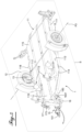
- the tilting and straightening system also allows the trailer 1 to pass from the lowered position to a so-called straightened position, in which the plate 11 is substantially perpendicular to the ground S.
- the straightened position is illustrated on the figure 7 And 11 .
- the plate 11 comprising a front part 116 and a rear part 115 movable relative to each other by rotation about an axis 117, the part 115 rear of the tray 11 is folded towards the front part 116 of the tray 11, as shown in the Figures 8A, 8B And 13 .
- the platform 11 When the platform 11 is in the folded position, the platform 11 does not protrude from the wheels 12 towards the rear of the trailer 1.
- At least one of the parts 115, 116 of the plate 11 comprises at least one buffer 118 defining, by abutment against the other of the parts 115, 116, the folded position of the plate 11.
- the buffer 118 allows the two parts 115, 116 of the plate 11 are not in direct contact so as not to damage the plate 11.
- the plate 11 is preferably held in the folded position by means of a strap (not shown).
- the rear part 115 of the plate 11 comprises at least one tab 119 projecting forward from the trailer 1 from the axis 117 of rotation of the plate 11.
- This tab 119 is intended to define , by a stop effect, the unfolded position of the plate 11 by contact between the tab 119 and the front part 116 of the plate 11.
- This tab 119 is adapted to be secured to the front part 116 of the plate 11 in order to maintain the plate 11 in unfolded position.
- the plate 11 can only be converted to its folded form when the trailer 1 is in the rolling position, otherwise the leg 119 comes into contact with the axle 14 which blocks the rotation of the rear part 115 of tray 11 and therefore the folding of the plate 11.
- the lowered position of the trailer 1 is reached by following the same steps as when the tray 11 is unfolded.
- a roller 152 mounted under the drawbar 15 and which had hitherto been retracted is unfolded and placed in front of the coupling head 151, as shown in the figure 9 . Furthermore, a jaw 19 blocking the drawbar 15 against the plate 11 is open, as shown in the figure 9 .
- the wheel 152 is able to pass from a retracted position behind the coupling head 151 to a position in front of the coupling head 151 by rotation under the drawbar 15.
- the drawbar 15 is further articulated to the plate 11 by a rotation axis P2 defining a pivot connection parallel to the axle 14.
- This axis P2 is arranged at one end of the drawbar 15 opposite to the coupling head 151 and under the plate. 11.
- This axis P2 is preferably disposed at about two-thirds of the distance between the axle 14 and the front of the plate 11, closer to the front of the plate 11 than to the axle 14.
- the jaw 19, secured to the plate 11 and placed in front of the latter maintains the drawbar 15 substantially parallel to the plate 11 and against the latter in the rolling and lowered positions of the trailer 1, preferably enclosing, the drawbar 15 to approximately one third of its length starting from its axis P2 of rotation.
- the axle 14 comprises a blocking plate 14a, visible in figure 3 , 4B , 6B , 8B And 9 to 11 , comprising a hole 14a1.
- a pin (not shown) is intended to be inserted in this hole 14a1 and in a hole 11a of the plate 11, said holes 11a, 14a1 being aligned when the trailer 1 is in the lowered position.
- the trailer 1 In the upright position, the trailer 1 rests on its wheels 12 and on the roller 152 allowing it to be moved easily.
- the drawbar 15 comprises a buffer 153 defining, by abutment against the plate 11, the upright position of the trailer 1.
- This buffer 153 allows the drawbar 15 and the plate 11 not to be in direct contact with so as not to damage them.
- the winch 171 is arranged above the drawbar 15, when the trailer is in the rolling position or in the lowered position.
- the trailer 1 comprises a pulley 154 comprising two rollers 1541 aligned substantially in a direction defined by the drawbar 15 and between which the cable 173 passes.
- the winch 171 is easier to access and the underside of the trailer 1 is less cluttered.
- the roller 1541 of the pulley arranged towards the rear of the trailer 1 makes it possible to guide the cable 173 between the winch 171 and the lever 172 when the trailer 1 is in the rolling position, in the lowered position and at the start of the straightening of the trailer 1, as shown in the figure 3 , 4B , 6B , 8B , 9 and 10 .
- the roller 1541 of the pulley arranged towards the front of the trailer 1 makes it possible to guide the cable 173 between the winch 171 and the lever 172 when the trailer 1 is at the end of straightening and in the straightened position, as represented on the figure 11 .
- This front roller 1541 is necessary, in the illustrated embodiment, because, in the upright position, the winch 171 is farther from the ground S than the lever 172.
- the tilting and straightening system also comprises an anchor 174 of the end of the cable 173 secured to the front of the plate 11.
- the cable 173 is fixed, by its two ends, to the winch 171 and to the anchor 174 and cable 173 passes through roller 1721 of lever 172.
- This anchor 174 makes it possible to divide by two the force to be provided, at the level of the winch 171, to compensate for the force required at the level of the lever 172 to cause the axle 14 to pivot.
- the trailer 1 comprises walls laterally delimiting the platform 11 and/or other attachment means and/or supports.
- the lowered position is reached when the axis P3 of the wheels 12 is substantially vertical to the axle 14.
- the trailer 1 does not include an axle 14 and the arms 13 are mounted directly under the platform 11 of the trailer 1.
- the trailer 1 is converted from the rolling position to the upright position without going through the lowered position.
- a cable of another material, a chain, a rope or a strap can be used.
- This trailer 1 thus makes it possible to facilitate its loading and unloading while reducing its size during storage by requiring only very little of the user.
Description
L'invention a trait à une remorque de transport inclinable et apte à être redressée, et plus particulièrement à une remorque ouverte de type plate-forme permettant à un utilisateur de charger et décharger seul des objets lourds et/ou encombrants sur une plate-forme de la remorque et par ailleurs apte à être stockée en position redressée.The invention relates to a transport trailer that can be tilted and adapted to be straightened, and more particularly to an open trailer of the platform type enabling a user to load and unload heavy and/or bulky objects on a platform by himself of the trailer and also capable of being stored in the upright position.
Dans le domaine automobile, les remorques ouvertes sont couramment utilisées pour transporter des objets et/ou des matériaux trop volumineux pour rentrer dans un véhicule fermé, pouvant salir un tel véhicule fermé ou encore pour augmenter la capacité de transport d'un véhicule tracteur. Une telle remorque ouverte peut éventuellement être, aux fins d'une utilisation donnée, fermée ou partiellement fermée à l'aide d'une bâche ou de toute structure amovible, puis rouverte pour une autre utilisation.In the automotive field, open trailers are commonly used to transport objects and/or materials that are too bulky to fit into a closed vehicle, which could dirty such a closed vehicle, or even to increase the transport capacity of a towing vehicle. Such an open trailer may optionally be, for the purposes of a given use, closed or partially closed using a tarpaulin or any removable structure, and then reopened for another use.
Les remorques comprennent généralement un plateau disposé pour le roulage sensiblement parallèle au sol et sur lequel sont placés les objets et/ou les matériaux à transporter.Trailers generally comprise a platform arranged for rolling substantially parallel to the ground and on which the objects and/or materials to be transported are placed.
Cependant, les plateaux des remorques sont disposés à une certaine distance du sol rendant difficile le chargement et le déchargement des objets et/ou des matériaux lourds et/ou encombrants.However, the trays of the trailers are arranged at a certain distance from the ground, making it difficult to load and unload heavy and/or bulky objects and/or materials.
Il est connu, pour faciliter le chargement et le déchargement d'une remorque, de proposer une remorque comprenant un plateau inclinable vers l'arrière de la remorque de sorte que l'arrière du plateau soit, en phase de chargement ou de déchargement, au contact du sol afin de définir une pente par rapport au sol. Ainsi, il est aisé pour un utilisateur de faire rouler l'objet (l'objet possédant au moins une roue ou étant par exemple posé sur un diable) ou le matériau (le matériau étant par exemple dans une brouette) à charger depuis le sol sur le plateau ou à décharger depuis le plateau vers le sol.It is known, to facilitate the loading and unloading of a trailer, to propose a trailer comprising a tilting platform towards the rear of the trailer so that the rear of the platform is, in the loading or unloading phase, at the contact with the ground in order to define a slope with respect to the ground. Thus, it is easy for a user to roll the object (the object having at least one wheel or being for example placed on a trolley) or the material (the material being for example in a wheelbarrow) to be loaded from the ground on the platform or to unload from the platform to the ground.
Le document
Un autre problème lié aux remorques est leur encombrement lorsqu'elles ne sont pas utilisées.Another issue with trailers is how bulky they are when not in use.
En effet, une remorque ouverte, présentant généralement une surface au sol importante comparée à sa hauteur, occupe, lorsqu'elle est en position de roulage et n'est pas utilisée mais au contraire stockée par exemple dans un garage, une surface au sol importante et un volume vide au-dessus de la remorque difficile voire impossible à utiliser.Indeed, an open trailer, generally having a large floor area compared to its height, occupies, when it is in the rolling position and is not used but on the contrary stored for example in a garage, a large floor area. and an empty volume above the trailer that is difficult or even impossible to use.
Il est connu, pour réduire l'encombrement d'une remorque non utilisée, de disposer la remorque dans une position dite redressée dans laquelle son plateau est disposé sensiblement perpendiculairement au sol. Ainsi, la surface au sol occupée par la remorque en position redressée est moins importante que lorsque la remorque est en position de roulage, ce qui diminue l'encombrement de la remorque.It is known, to reduce the size of an unused trailer, to place the trailer in a so-called upright position in which its plate is placed substantially perpendicular to the ground. Thus, the ground surface occupied by the trailer in the upright position is smaller than when the trailer is in the rolling position, which reduces the size of the trailer.
La remorque décrite dans le document
Cependant, le redressement de la remorque est fait à la force de l'utilisateur. Ainsi, redresser une telle remorque peut être compliqué voire impossible en fonction de la masse de la remorque et de la force physique de l'utilisateur.However, the righting of the trailer is done by the force of the user. Thus, straightening such a trailer can be complicated or even impossible depending on the mass of the trailer and the physical strength of the user.
Le document
Une telle remorque est ainsi apte à être convertie de la position de roulage à la position redressée et inversement en ne sollicitant l'utilisateur que pour l'actionnement du treuil. Ainsi, un utilisateur est apte à redresser une remorque ayant une masse importante. Mais cette remorque n'est pas commode à utiliser, le seuil de chargement étant élevé et ne pouvant pas être abaissé.
- Le document n°
US5924836 - Le document n°
US2010/0084839A1 - Le document n°
US2007/0018429A1
- Document No.
US5924836 - Document No.
US2010/0084839A1 - Document No.
US2007/0018429A1
L'objectif de l'invention est de proposer une remorque comprenant un plateau inclinable afin de faciliter le chargement et le déchargement de la remorque et apte à être disposée dans une position redressée, réduisant l'encombrement de la remorque lorsqu'elle n'est pas utilisée, en sollicitant l'utilisateur le moins possible.The object of the invention is to provide a trailer comprising a tilting platform in order to facilitate the loading and unloading of the trailer and able to be placed in an upright position, reducing the size of the trailer when it is not not used, requiring the user as little as possible.
A cet effet, il est proposé, en premier lieu, une remorque comprenant un cadre, un plateau solidaire du cadre, le plateau étant destiné à supporter des objets et/ou des matériaux à transporter, des roues solidaires du cadre, les roues étant destinées à reposer sur le sol, un timon en liaison pivot avec le cadre, la liaison pivot étant sensiblement parallèle aux axes des roues et permettant le repliement du timon contre la surface inférieure du plateau.To this end, it is proposed, in the first place, a trailer comprising a frame, a plate fixed to the frame, the plate being intended to support objects and/or materials to be transported, wheels fixed to the frame, the wheels being intended to rest on the ground, a drawbar in pivot connection with the frame, the pivot connection being substantially parallel to the axes of the wheels and allowing the folding of the drawbar against the lower surface of the plate.
Le timon est en saillie du plateau dans une direction sensiblement perpendiculaire aux axes des roues, la remorque comprenant en outre un moyen de blocage de la liaison pivot et un système de conversion comprenant un moyen de traction, par exemple un élément longiligne souple non élastique solidaire du plateau et un dispositif de réglage de la longueur dudit élément, la longueur dudit élément définissant la distance d'au moins une partie du plateau par rapport au sol par pivotement du plateau autour d'une liaison pivot de chargement et déchargement parallèle aux axes des roues.The drawbar projects from the platform in a direction substantially perpendicular to the axles of the wheels, the trailer further comprising a means for locking the pivot connection and a conversion system comprising a traction means, for example a non-elastic flexible slender element integral of the plate and a device for adjusting the length of said element, the length of said element defining the distance of at least part of the plate relative to the ground by pivoting of the plate around a pivot link for loading and unloading parallel to the axes of the wheels.
Par ailleurs, la remorque est de plus apte à être disposée dans une position redressée dans laquelle le plateau est sensiblement perpendiculaire au sol.Furthermore, the trailer is also able to be placed in a straightened position in which the platform is substantially perpendicular to the ground.
Une telle remorque permet ainsi d'abaisser le plateau de la remorque pour faciliter le chargement et le déchargement de celle-ci. Une telle remorque permet également de réduire son encombrement lorsqu'elle n'est pas utilisée en la positionnant dans la position redressée.Such a trailer thus makes it possible to lower the platform of the trailer to facilitate the loading and unloading of the latter. Such a trailer also makes it possible to reduce its size when not in use by positioning it in the upright position.
De plus, le dispositif de réglage de la longueur de l'élément longiligne souple, ou plus généralement, le dispositif de commande de l'élément de traction est fixé au timon, ou monté sur le timon. Ainsi, il peut provoquer la rotation du timon autour de son pivot, si le pivot est débloqué, et le redressement de la remorque sur ses roues.In addition, the device for adjusting the length of the flexible slender element, or more generally, the device for controlling the traction element is fixed to the drawbar, or mounted on the drawbar. Thus, it can cause the rotation of the drawbar around its pivot, if the pivot is released, and the recovery of the trailer on its wheels.
Ainsi, le dispositif de conversion permet, outre de convertir la remorque entre les positions de roulage et abaissée, de convertir la remorque en position redressée. Cette dernière conversion ne sollicite que très peu l'utilisateur et permet la conception d'une remorque simple dans laquelle un unique dispositif de conversion permet de passer, en minimisant les efforts entre trois positions différentes.Thus, the conversion device makes it possible, in addition to converting the trailer between the rolling and lowered positions, to convert the trailer to the upright position. This last conversion requires very little user and allows the design of a simple trailer in which a single conversion device can pass, minimizing the efforts between three different positions.
Diverses caractéristiques supplémentaires peuvent être prévues, seules ou en combinaison :
- la remorque comprend des bras, chaque bras solidarisant une des roues au cadre, les bras étant en liaison pivot avec le cadre, les liaisons pivot étant différentes des axes des roues, la remorque comprenant en outre un moyen de blocage de la liaison pivot ;
- la remorque comprend une poulie solidaire du timon, la poulie comportant deux rouleaux disposés successivement sensiblement suivant la direction de saillie du timon, l'élément longiligne souple passant entre les deux rouleaux, en sorte d'être couplé à l'un ou l'autre en fonction de la position du timon vis-à-vis du plateau ;
- la remorque comprend une roulette solidaire du timon, la roulette étant apte à être escamotée entre les extrémités du timon ou à être dépliée à l'extrémité du timon opposée au plateau pour servir d'appui ;
- le plateau comprend une partie arrière et une partie avant mobiles l'une par rapport à l'autre par rotation autour d'un axe de pliage, l'axe de pliage étant disposé entre le timon et la partie des roues la plus éloignée du timon.
- the trailer comprises arms, each arm securing one of the wheels to the frame, the arms being in a pivot connection with the frame, the pivot connections being different from the axles of the wheels, the trailer further comprising means for locking the pivot connection;
- the trailer comprises a pulley integral with the drawbar, the pulley comprising two rollers arranged successively substantially in the direction of projection of the drawbar, the flexible slender element passing between the two rollers, so as to be coupled to one or the other depending on the position of the tiller vis-à-vis the platform;
- the trailer comprises a caster secured to the drawbar, the caster being adapted to be retracted between the ends of the drawbar or to be unfolded at the end of the drawbar opposite the plate to serve as a support;
- the platform comprises a rear part and a front part movable relative to each other by rotation about a folding axis, the folding axis being arranged between the drawbar and the part of the wheels farthest from the drawbar .
Il est proposé, en second lieu, un procédé de conversion d'une remorque entre une position de roulage dans laquelle des roues de la remorque reposent sur le sol, une position abaissée dans laquelle au moins une partie d'un plateau de la remorque est plus proche du sol que dans la position de roulage, le plateau étant destiné à supporter des objets et/ou des matériaux à transporter, et une position redressée dans laquelle le plateau est sensiblement perpendiculaire au sol, le procédé comprenant, pour convertir la remorque entre la position de roulage et la position abaissée, une variation d'une longueur d'un élément longiligne souple de la remorque, le procédé comprenant, pour convertir la remorque entre la position de roulage et la position abaissée, un blocage d'une liaison pivot d'un timon de la remorque avec un cadre de la remorque, le plateau étant solidaire du cadre et le timon s'étendant suivant une direction sensiblement perpendiculaire à ladite liaison pivot, et en ce qu'il comprend, pour convertir la remorque vers la position redressée, un déblocage de ladite liaison pivot et une modification de la longueur de l'élément longiligne souple.Secondly, a method of converting a trailer between a rolling position in which the wheels of the trailer rest on the ground, a lowered position in which at least a part of a bed of the trailer is closer to the ground than in the rolling position, the tray being intended to support objects and/or materials to be transported, and an upright position in which the tray is substantially perpendicular to the ground, the method comprising, to convert the trailer between the rolling position and the lowered position, a variation of a length of a flexible elongate element of the trailer, the method comprising, to convert the trailer between the rolling and the lowered position, blocking of a pivot connection of a drawbar of the trailer with a frame of the trailer, the plate being integral with the frame and the drawbar extending in a direction substantially perpendicular to said pivot connection, and in that it comprises, to convert the trailer to the upright position, an unlocking of said pivot connection and a modification of the length of the flexible slender element.
Diverses caractéristiques supplémentaires peuvent être prévues, seules ou en combinaison :
- le procédé comprend en outre, pour convertir la remorque vers la position redressée, une disposition d'une roulette à l'extrémité du timon opposée au plateau et une réduction de la longueur de l'élément longiligne souple et le procédé comprend, pour convertir la remorque depuis la position redressée, une augmentation de la longueur de l'élément longiligne souple, une disposition de la roulette entre les extrémités du timon et le blocage de la liaison pivot ;
- le procédé comprend un pliage préalable d'une partie arrière et d'une partie avant du plateau l'une contre l'autre, des roues de la remorque dépassant du plateau à l'opposé du timon ;
- le pliage du plateau est réalisé lorsque la remorque est en position de roulage ;
- comprend, lorsque la remorque est en position redressée, un déplacement de la remorque sur ses roues et sa roulette.
- the method further comprises, to convert the trailer to the upright position, a provision of a wheel at the end of the drawbar opposite the platform and a reduction in the length of the flexible slender element and the method comprises, to convert the trailer from the upright position, an increase in the length of the flexible slender element, an arrangement of the wheel between the ends of the drawbar and the blocking of the pivot link;
- the method comprises prior folding of a rear part and a front part of the platform against each other, the wheels of the trailer protruding from the platform opposite the drawbar;
- the folding of the platform is carried out when the trailer is in the rolling position;
- includes, when the trailer is in the upright position, a movement of the trailer on its wheels and caster.
L'invention sera mieux comprise, et d'autres buts, caractéristiques, détails et avantages de celle-ci apparaîtront plus clairement dans la description explicative qui va suivre faite en référence aux dessins annexés donnés uniquement à titre d'exemple illustrant un mode de réalisation de l'invention et dans lesquels :
- [
Fig. 1 ] - lafigure 1 est une vue schématique en perspective de dessus d'une remorque en position de roulage ; - [
Fig. 2 ] - Lafigure 2 est une vue schématique en perspective de dessous de la remorque de lafigure 1 en position de roulage ; - [
Fig. 3 ] - Lafigure 3 est une vue schématique de dessous de la même remorque en position de roulage ; - [
Fig. 4A ] - Lafigure 4A est une vue schématique en coupe au niveau d'un plan G-G représenté sur lafigure 3 du côté gauche de la remorque en position de roulage ; - [
Fig. 4B ] - Lafigure 4B est une vue schématique en coupe au niveau d'un plan D-D représenté sur lafigure 3 du côté droit de la remorque en position de roulage, comme enfigure 4A ; - [
Fig. 5 ] - Lafigure 5 est une vue schématique en perspective de dessus de la remorque de lafigure 1 en position abaissée ; - [
Fig. 6A ] - Lafigure 6A est une vue schématique en coupe au niveau du plan G-G du côté gauche de la remorque en position abaissée ; - [
Fig. 6B ] - Lafigure 6B est une vue schématique en coupe au niveau du plan D-D du côté droit de la remorque en position abaissée, comme enfigure 6A ; - [
Fig. 7 ] - Lafigure 7 est une vue schématique en perspective de la remorque de lafigure 1 en position redressée, le plateau étant dans une position pliée ; - [
Fig. 8A ] - Lafigure 8A est une vue schématique en coupe au niveau du plan G-G du côté gauche de la remorque en position abaissée mais pas encore redressée, le plateau étant dans une position pliée ; - [
Fig. 8B ] - Lafigure 8B est une vue schématique en coupe au niveau du plan D-D du côté droit de la remorque en position abaissée mais pas encore redressée, le plateau étant dans la position pliée, comme enfigure 8A ; - [
Fig. 9 ] - Lafigure 9 est une vue schématique en coupe au niveau du plan D-D du côté droit de la remorque en position abaissée, le plateau étant dans la position pliée, une roulette étant dans une position déployée et une mâchoire étant dans une position ouverte, aux fins de procéder au redressement de la remorque ; - [
Fig. 10 ] - Lafigure 10 est une vue schématique en coupe au niveau du plan D-D du côté droit de la remorque dans une position intermédiaire, entre la position représentée sur lafigure 9 et la position redressée représentée sur lafigure 7 ; - [
Fig. 11 ] - Lafigure 11 est une vue schématique en coupe au niveau du plan D-D du côté droit de la remorque en position redressée, comme représenté sure lafigure 7 ; - [
Fig. 12 ] - Lafigure 12 est un organigramme représentant les étapes de conversion de la remorque de la position de roulage à la position abaissée et inversement ; - [
Fig. 13 ] - Lafigure 13 est un organigramme représentant les étapes de conversion de la remorque de la position de roulage à la position redressée et inversement.
- [
Fig. 1 ] - therefigure 1 is a schematic perspective view from above of a trailer in the rolling position; - [
Fig. 2 ] - Therefigure 2 is a schematic perspective view from below of the trailer of thefigure 1 in the rolling position; - [
Fig. 3 ] - Therepicture 3 is a schematic bottom view of the same trailer in the rolling position; - [
Fig. 4A ] - Therefigure 4A is a schematic sectional view at the level of a GG plane represented on thepicture 3 on the left side of the trailer in the rolling position; - [
Fig. 4B ] - Therefigure 4B is a schematic sectional view at the level of a DD plane represented on thepicture 3 on the right side of the trailer in the driving position, as infigure 4A ; - [
Fig. 5 ] - Therefigure 5 is a schematic perspective view from above of the trailer of thefigure 1 in the lowered position; - [
Fig. 6A ] - ThereFigure 6A is a schematic sectional view at the level of the plane GG of the left side of the trailer in the lowered position; - [
Fig. 6B ] - Therefigure 6B is a schematic sectional view at the DD plane of the right side of the trailer in the lowered position, as inFigure 6A ; - [
Fig. 7 ] - Therefigure 7 is a schematic perspective view of the trailer of thefigure 1 in the upright position, the tray being in a folded position; - [
Fig. 8A ] - Therefigure 8A is a schematic sectional view at the level of the plane GG of the left side of the trailer in the lowered position but not yet straightened, the bed being in a folded position; - [
Fig. 8B ] - Therefigure 8B is a schematic cross-sectional view at the DD plane of the right side of the trailer in the lowered position but not yet straightened, the bed being in the folded position, as infigure 8A ; - [
Fig. 9 ] - Therefigure 9 is a schematic cross-sectional view at the plane DD of the right side of the trailer in the lowered position, the bed being in the folded position, a caster being in an extended position and a jaw being in an open position, for the purpose of carrying out the trailer straightening; - [
Fig. 10 ] - Therefigure 10 is a schematic sectional view at the level of the DD plane of the right side of the trailer in an intermediate position, between the position shown in thefigure 9 and the upright position shown on thefigure 7 ; - [
Fig. 11 ] - Therefigure 11 is a schematic cross-sectional view at the DD plane of the right side of the trailer in the upright position, as shown in figurefigure 7 ; - [
Fig. 12 ] - Therefigure 12 is a flowchart representing the steps for converting the trailer from the rolling position to the lowered position and vice versa; - [
Fig. 13 ] - Therefigure 13 is a flowchart representing the steps for converting the trailer from the rolling position to the upright position and vice versa.
Les
Le plateau 11 est destiné à recevoir des objets et/ou des matériaux afin de les transporter.The
Selon le mode de réalisation représenté, le plateau 11 comprend un cadre 111 périphérique et un plancher 112 de préférence en tôle.According to the embodiment shown, the
Selon le mode de réalisation illustré, la remorque 1 est apte à transporter deux motocyclettes. Pour ce faire, la remorque 1 comprend sur son plateau 11 deux supports 113 destinés à bloquer chacun la roue avant d'une motocyclette disposée sur la remorque 1. La remorque 1 comprend également des moyens 114 d'attache permettant de sangler les motocyclettes ou tout autre objet disposé sur la remorque 1.According to the illustrated embodiment, the
La remorque 1 comprend une roue 16 jockey solidaire du timon 15. La roue 16 jockey peut prendre deux positions : une position déployée de sorte à soutenir le timon 15 par appui sur le sol S lorsque cela est nécessaire, notamment lorsque la remorque n'est pas attachée à un véhicule tracteur, et une position rétractée en sorte de ne pas gêner la manoeuvre de la remorque en situation de roulage.The
Comme on peut le voir sur la
L'essieu 14 est monté en liaison pivot P1 d'axe horizontal avec le plateau 11 de la remorque 1.The
La remorque 1 comprend également un système d'inclinaison et de redressement. Ledit système comprend un treuil 171 monté sur le timon 15, au-delà de la limite du plateau, et un levier 172 dont une première extrémité est fixée par encastrement à l'essieu 14 aux environs de la moitié de sa longueur, sous le plateau. Le système d'inclinaison et de redressement comprend de plus un câble 173, métallique (en acier, par exemple) reliant, sous l'avant du plateau, le treuil 171, sur lequel il s'enroule, et la deuxième extrémité du levier 172. Le levier 172 comporte de plus, en cette deuxième extrémité, un rouleau 1721 sur lequel le câble 173 est monté coulissant en sorte de le maintenir éloigné de l'essieu 14 tout en permettant un renvoi angulaire d'une traction appliquée sur le câble 173 par le treuil. Le renvoie angulaire est effectué vers l'avant de la remorque, sous le plateau, et jusqu' à un point d'accroche fixe de l'extrémité du câble, à la partie avant du plateau.
Ce système d'inclinaison et de redressement permet à la remorque 1 d'être convertie d'une position de roulage, dans laquelle son plateau 11 est sensiblement parallèle au sol S, à une position abaissée, dans laquelle le plateau 11 est incliné par rapport au sol S. La position de roulage est illustrée sur les
Dans la position de roulage, l'axe P3 de rotation des deux roues 12 n'est pas disposé à la verticale de l'essieu 14. Ainsi, comme illustré sur la
Selon le mode de réalisation illustré, la position abaissée est atteinte lorsque la partie 115 arrière du plateau 11 est au contact du sol S.According to the illustrated embodiment, the lowered position is reached when the
A l'inverse, comme illustré sur la
Selon le mode de réalisation représenté, en position de roulage, les bras 13 sont orientés de sorte que l'axe P3 des roues 12 soit disposé vers l'arrière de la remorque 1 et plus bas que l'essieu 14.According to the embodiment shown, in the rolling position, the
De plus, selon un mode de réalisation, l'essieu 14 comprend une pièce externe fixée au cadre 111 et une pièce interne solidaire de la pièce externe par des amortisseurs. Les bras 13 sont fixés à la pièce interne. Ainsi, en phase de roulage, les bras 13 sollicitent les amortisseurs par le biais de la pièce interne ce qui amorti les vibrations dues au roulage.Moreover, according to one embodiment, the
Selon le mode de réalisation illustré, et comme cela est visible en
Ainsi, grâce à l'orientation des bras 13, le rouleau 1721 du levier 172 s'éloigne du treuil 171 et s'abaisse lorsque la remorque est convertie de sa position de roulage à sa position abaissée. Cela est visible en comparant les
L'avantage de la position du levier 172 en position de roulage et de son mouvement pour passer en position abaissée est que le levier 172 ne peut pas entrer en contact avec le plateau 11 ce qui permet de rapprocher l'essieu 14 du plateau 11 de sorte à réduire l'inclinaison du plateau 11 en position abaissée et à abaisser le centre de gravité de la remorque 1.The advantage of the position of the
Selon le mode de réalisation représenté, en particulier sur les
Ainsi, la liaison pivot P1 entre l'essieu 14 et le plateau 11 est apte à être bloquée au niveau du timon 15 ce qui entraine le verrouillage de la remorque 1 en position de roulage par le système 18 de verrouillage, ce qui permet de réduire la tension du câble 173 en position de roulage.Thus, the pivot connection P1 between the
Selon le mode de réalisation illustré, le moyen 1821 de blocage de la barre 182 de blocage comprend une pièce 1822 plane comportant un trou 1823. Le moyen 183 de blocage solidaire du plateau 11 comprend une fente 1831 destinée à laisser entrer la pièce 1822 plane lorsque la remorque 1 est en position de roulage. Une goupille g est destinée à venir se loger dans le trou 1823 de la pièce 1822 plane lorsqu'elle est dans la fente 1831 empêchant la pièce 1822 plane de ressortir de la fente 1831.According to the illustrated embodiment, the locking means 1821 of the locking
Selon le mode de réalisation illustré, le système 18 de verrouillage comprend une glissière 184 dans laquelle passe la barre 182 de blocage. La glissière 184 maintient la barre 182 de blocage du côté de son moyen 1821 de blocage de sorte que, lorsque la remorque 1 est convertie en position de roulage, la pièce 1822 plane entre automatiquement dans la fente 1831.According to the illustrated embodiment, the locking
Le système d'inclinaison et de redressement permet également à la remorque 1 de passer de la position abaissée à une position dite redressée, dans laquelle le plateau 11 est sensiblement perpendiculaire au sol S. La position redressée est illustrée sur les
Selon le mode de réalisation représenté, pour convertir la remorque 1 en position redressée, le plateau 11 comprenant une partie 116 avant et une partie 115 arrière mobiles l'une par rapport à l'autre par rotation autour d'un axe 117, la partie 115 arrière du plateau 11 est pliée vers la partie 116 avant du plateau 11, comme représenté sur les
Au moins l'une des parties 115, 116 du plateau 11 comprend au moins un tampon 118 définissant, par buttée contre l'autre des parties 115, 116, la position pliée du plateau 11. Le tampon 118 permet que les deux parties 115, 116 du plateau 11 ne soient pas en contact direct de sorte à ne pas abîmer le plateau 11. Le plateau 11 est de préférence maintenu en position pliée au moyen d'une sangle (non représentée).At least one of the
Selon le mode de réalisation illustré, la partie 115 arrière du plateau 11 comprend au moins une patte 119 en saillie vers l'avant de la remorque 1 à partir de l'axe 117 de rotation du plateau 11. Cette patte 119 est destinée à définir, par un effet de butée, la position dépliée du plateau 11 par contact entre la patte 119 et la partie 116 avant du plateau 11. Cette patte 119 est apte à être solidarisée à la partie 116 avant du plateau 11 afin de maintenir le plateau 11 en position dépliée.According to the illustrated embodiment, the
Selon le mode de réalisation illustré, le plateau 11 ne peut être converti vers sa forme pliée que lorsque la remorque 1 est en position de roulage sinon la patte 119 entre en contact avec l'essieu 14 ce qui bloque la rotation de la partie 115 arrière du plateau 11 et donc le pliage du plateau 11. Pour atteindre la forme plateau 11 plié et remorque inclinée, il convient donc, selon le mode de réalisation représenté, en particulier sur la
La position abaissée de la remorque 1 est atteinte en suivant les mêmes étapes que lorsque le plateau 11 est déplié.The lowered position of the
Une fois le plateau 11 en position pliée et la remorque 1 en position abaissée, comme représenté sur les
Plus précisément, selon le mode de réalisation représenté, la roulette 152 est apte à passer d'une position escamotée en arrière de la tête 151 d'attelage à une position en avant de la tête 151 d'attelage par rotation sous le timon 15.More specifically, according to the embodiment shown, the
Le timon 15 est de plus articulé au plateau 11 par un axe P2 de rotation définissant une liaison pivot parallèle à l'essieu 14. Cet axe P2 est disposé à une extrémité du timon 15 opposée à la tête 151 d'attelage et sous le plateau 11. Cet axe P2 est, de préférence, disposé à environ les deux-tiers de la distance entre l'essieu 14 et l'avant du plateau 11, plus proche de l'avant du plateau 11 que de l'essieu 14. La mâchoire 19, solidaire du plateau 11 et placée à l'avant de celui-ci, maintient le timon 15 sensiblement parallèle au plateau 11 et contre celui-ci dans les positions de roulage et abaissée de la remorque 1, en enserrant, de préférence, le timon 15 à environ un tiers de sa longueur en partant de son axe P2 de rotation.The
De plus, pour redresser la remorque selon le mode de réalisation illustré, le pivotement de l'essieu 14 par rapport au plateau 11 autour de la liaison pivot P1 est bloqué au niveau de l'essieu 14. Pour ce faire, selon le mode de réalisation représenté, l'essieu 14 comprend une plaque 14a de blocage, visible en
Une fois le plateau 11 en position pliée, la remorque 1 en position abaissée, la roulette 152 disposée en avant de la tête 151 d'attelage, la mâchoire 19 ouverte et le pivotement de l'essieu 14 par rapport au plateau 11 bloqué, le redressement de la remorque 1 se fait par enroulement du câble 173 sur le treuil 171.Once the
La
Comme on peut le voir sur la
Dans un second temps, le timon 15, continuant à pivoter, repose sur la roulette 152, la roue 16 jockey ne touchant plus le sol S, comme représenté sur la
En position redressée, la remorque 1 repose sur ses roues 12 et sur la roulette 152 permettant de la déplacer facilement.In the upright position, the
Pour convertir la remorque 1 de la position redressée à la position de roulage, les mêmes étapes en sens inverse sont réalisées, comme représenté sur la
Selon le mode de réalisation représenté, le timon 15 comprend un tampon 153 définissant, par buttée contre le plateau 11, la position redressée de la remorque 1. Ce tampon 153 permet que le timon 15 et le plateau 11 ne soient pas en contact direct de sorte à ne pas les abîmer.According to the embodiment shown, the
Selon le mode de réalisation représenté, le treuil 171 est disposé au-dessus du timon 15, lorsque la remorque est en position de roulage ou en position abaissée. La remorque 1 comprend une poulie 154 comportant deux rouleaux 1541 alignés sensiblement suivant une direction définie par le timon 15 et entre lesquels passe le câble 173.According to the embodiment shown, the
Ainsi, le treuil 171 est plus facile d'accès et le dessous de la remorque 1 est moins encombré.Thus, the
Le rouleau 1541 de la poulie disposé vers l'arrière de la remorque 1 permet de guider le câble 173 entre le treuil 171 et le levier 172 lorsque la remorque 1 est en position de roulage, en position abaissée et au début du redressage de la remorque 1, comme représenté sur les
Le rouleau 1541 de la poulie disposé vers l'avant de la remorque 1 permet de guider le câble 173 entre le treuil 171 et le levier 172 lorsque la remorque 1 est en fin de redressement et en position redressée, comme représenté sur la
Selon le mode de réalisation représenté, en particulier sur les
Cet ancrage 174 permet de diviser par deux la force à fournir, au niveau du treuil 171, pour compenser la force requise au niveau du levier 172 pour faire pivoter l'essieu 14.This
Selon des modes de réalisation différents, la remorque 1 comprend des parois délimitant latéralement le plateau 11 et/ou d'autres moyens d'attache et/ou supports.According to different embodiments, the
Selon des modes de réalisation différents, la position abaissée est atteinte lorsque l'axe P3 des roues 12 est sensiblement à la verticale de l'essieu 14.According to different embodiments, the lowered position is reached when the axis P3 of the
Selon des modes de réalisation différents, la remorque 1 ne comprend pas d'essieu 14 et les bras 13 sont directement montés sous le plateau 11 de la remorque 1.According to different embodiments, the
Selon des modes de réalisation différents, la remorque 1 est convertie de la position de roulage à la position redressée sans passer par la position abaissée.According to different embodiments, the
A la place du câble 173 en acier, on peut utiliser un câble dans un autre matériau, une chaîne, une corde ou une sangle.Instead of the
Cette remorque 1 permet ainsi de faciliter son chargement et son déchargement tout en réduisant son encombrement lors de son stockage en ne sollicitant que très peu l'utilisateur.This
Claims (10)
- A trailer (1) comprising a transport deck (11), wheels (12), a draw bar (15) that is in a draw bar pivot connection (P2) with the deck (11), the draw bar pivot connection (P2) being parallel to the axes (P3) of the wheels (12) and allowing the draw bar to be folded back against the lower surface of the deck, the trailer (1) further comprising a means (19) for immobilizing and releasing the draw bar pivot connection (P2) and a converting system comprising a traction means (171, 173) for the deck (11) defining a distance between the deck (11) and the ground (S) by pivoting the deck (11) about a loading and unloading pivot connection (P1) parallel to the axes (P3) of the wheels, the trailer (1) further being able to be arranged in a righted position, the trailer (1) being characterized in that a device (171) for controlling the traction means is mounted on the draw bar (15).
- The trailer (1) according to the preceding claim, characterized in that it comprises arms (13), each arm (13) securing one of the wheels (12) to the deck (11), the arms (13) being connected to the deck (11) by the loading and unloading pivot connection (P1), the loading and unloading pivot connection (P1) being different from the axes (P3) of the wheels (12), the trailer (1) further comprising a means (11a, 14a) for immobilizing the loading and unloading pivot connection (P1).
- The trailer (1) according to any one of the preceding claims, characterized in that it comprises a pulley (154) secured to the draw bar (15), the pulley (154) comprising two rollers (1541) arranged successively in the direction of projection of the draw bar (15), the traction means (173) passing between the two rollers (1541) so as to be coupled to one or the other.
- The trailer (1) according to any one of the preceding claims, characterized in that it comprises a caster (152) secured to the draw bar (15), the caster (152) being able to be retracted between the ends of the draw bar (15) or to be unfolded at the end of the draw bar (15) opposite the deck (11) in order to act as a support.
- The trailer (1) according to any one of the preceding claims, characterized in that the deck (11) comprises a rear portion (115) and a front portion (116) which are movable relative to one another by rotation about a folding axis (117), the folding axis (117) being arranged between the draw bar (15) and the portion of the wheels (12) furthest from the draw bar (15).
- The trailer (1) according to any one of the preceding claims, characterized in that the traction means (171, 173) for the deck (11) comprises a metal cable and the device (171) for controlling said traction means (171, 173) is a winch (171).
- The trailer (1) according to any one of the preceding claims, characterized in that the means for immobilizing and releasing the draw bar is a jaw placed in front of the deck.
- A method of converting a trailer (1) according to one of claims 1 to 7 between a rolling position in which wheels (12) of the trailer (1) rest on the ground (S), a lowered position in which at least one part of a deck (11) of the trailer (1) is closer to the ground (S) than in the rolling position, the deck (11) being intended to support objects and/or materials to be transported, and a righted position, the method comprising, in order to convert the trailer (1) between the rolling position and the lowered position, varying a length of a traction means (173) of the trailer (1), the method being characterized in that it comprises, in order to convert the trailer (1) from the rolling position to the lowered position, immobilizing a draw bar pivot connection (P2) of a draw bar (15) of the trailer (1) to a deck (11) of the trailer (1), the draw bar (15) extending in a direction perpendicular to said draw bar pivot connection (P2), and in that it comprises, in order to convert the trailer (1) to the righted position, releasing said draw bar pivot connection (P2) and modifying the length of the traction means (173).
- The conversion method according to the preceding claim, characterized in that it further comprises, in order to convert the trailer to the righted position, arranging a caster (152) at the end of the draw bar (15) opposite the deck (11) and reducing the length of the traction means (173), and in that it comprises, in order to convert the trailer from the righted position, increasing the length of the traction means (173), arranging the caster (152) between the ends of the draw bar (15), and immobilizing the draw bar pivot connection (P2) .
- The conversion method according to any one of claims 7 or 8, characterized in that it comprises, in order to convert the trailer to the righted position, pre-folding a rear portion (115) and a front portion (116) of the trailer deck (11) against one another, wheels (12) of the trailer (1) projecting from the deck (11) opposite the draw bar (15), a rear portion (115) and a front portion (116) of the deck (11) being folded against one another when the trailer (1) is in a rolling position.
Applications Claiming Priority (2)
| Application Number | Priority Date | Filing Date | Title |
|---|---|---|---|
| FR2000132A FR3105965B1 (en) | 2020-01-08 | 2020-01-08 | Transport trailer including a system for tilting and straightening its platform. |
| PCT/FR2021/050017 WO2021140299A1 (en) | 2020-01-08 | 2021-01-07 | Transport trailer comprising a system for tilting and righting its deck |
Publications (3)
| Publication Number | Publication Date |
|---|---|
| EP4087772A1 EP4087772A1 (en) | 2022-11-16 |
| EP4087772B1 true EP4087772B1 (en) | 2023-08-23 |
| EP4087772C0 EP4087772C0 (en) | 2023-08-23 |
Family
ID=70614029
Family Applications (1)
| Application Number | Title | Priority Date | Filing Date |
|---|---|---|---|
| EP21704602.8A Active EP4087772B1 (en) | 2020-01-08 | 2021-01-07 | Transport trailer comprising a system for tilting and righting its deck |
Country Status (5)
| Country | Link |
|---|---|
| US (1) | US20230123044A1 (en) |
| EP (1) | EP4087772B1 (en) |
| CA (1) | CA3167372A1 (en) |
| FR (1) | FR3105965B1 (en) |
| WO (1) | WO2021140299A1 (en) |
Families Citing this family (2)
| Publication number | Priority date | Publication date | Assignee | Title |
|---|---|---|---|---|
| US20210362763A1 (en) * | 2020-05-20 | 2021-11-25 | Urban Electric Co. | Vehicle, Trailer, and Cart Control Systems |
| US11623704B2 (en) * | 2020-06-17 | 2023-04-11 | Robert Taylor | Retractable on-board vehicle trailer |
Family Cites Families (7)
| Publication number | Priority date | Publication date | Assignee | Title |
|---|---|---|---|---|
| US4077643A (en) * | 1976-07-12 | 1978-03-07 | Bates Dean E | Drop frame trailer |
| US5924836A (en) * | 1996-08-22 | 1999-07-20 | Advanced Industries, Inc. | Folding and tilting trailer |
| US20070018429A1 (en) * | 2005-07-22 | 2007-01-25 | Clark Randall | Foldable trailer with joint hinge and cantilever mechanism |
| FR2908103B1 (en) * | 2006-11-02 | 2009-01-16 | Ignace Ansidei | TILT-TYPE TRAILER HAVING A LOADING AND UNLOADING DEVICE OF A LOAD |
| NO326802B1 (en) | 2007-06-01 | 2009-02-16 | Eirik Oyasaeter | Foldable trailer |
| US8360462B2 (en) * | 2008-10-02 | 2013-01-29 | Baxley Blowpipe Company, Inc. | Folding trailer |
| FR3078031B1 (en) | 2018-02-22 | 2021-02-12 | Cochet | TILTING TRAILER INCLUDING MECHANICAL ACTUATION AND LOCKING MEANS IN HIGH POSITION |
-
2020
- 2020-01-08 FR FR2000132A patent/FR3105965B1/en active Active
-
2021
- 2021-01-07 US US17/791,664 patent/US20230123044A1/en active Pending
- 2021-01-07 WO PCT/FR2021/050017 patent/WO2021140299A1/en unknown
- 2021-01-07 CA CA3167372A patent/CA3167372A1/en active Pending
- 2021-01-07 EP EP21704602.8A patent/EP4087772B1/en active Active
Also Published As
| Publication number | Publication date |
|---|---|
| CA3167372A1 (en) | 2021-07-15 |
| FR3105965A1 (en) | 2021-07-09 |
| US20230123044A1 (en) | 2023-04-20 |
| EP4087772C0 (en) | 2023-08-23 |
| EP4087772A1 (en) | 2022-11-16 |
| FR3105965B1 (en) | 2021-12-31 |
| WO2021140299A1 (en) | 2021-07-15 |
Similar Documents
| Publication | Publication Date | Title |
|---|---|---|
| EP4087772B1 (en) | Transport trailer comprising a system for tilting and righting its deck | |
| EP3755575B1 (en) | Tiltable trailer comprising mechanical actuation means and high-position locking means | |
| WO1987006570A1 (en) | Handling-trucking device and element for containers or the like | |
| EP0199652B1 (en) | Container-handling device | |
| FR2822421A1 (en) | LOAD HANDLING APPARATUS AND VEHICLE COMPRISING SAME | |
| EP2946994B1 (en) | Trailer for two-wheeled vehicle | |
| EP2303632A2 (en) | Handling-trucking device for a container or the like, and method for moving such devices in the absence of a container | |
| FR2945523A1 (en) | DEVICE FOR TRANSPORTING OBJECTS, IN PARTICULAR PREFABRICATED ELEMENTS IN THE FORM OF PLATES. | |
| FR2667283A1 (en) | Tarpaulin-covered vehicle with fold-up tarpaulin and removable uprights | |
| WO2022259194A1 (en) | Recovery-towing assembly for a towing vehicle, and towing vehicle comprising same | |
| FR2560129A1 (en) | Transport vehicle, especially for a tubular load of very great diameter | |
| EP3835133B1 (en) | Device for placing an object on a vehicle roof | |
| EP1209027B1 (en) | Light utility vehicle with a removable container | |
| FR3112753A1 (en) | Light vehicle trailer | |
| EP3156268B1 (en) | Trailer comprising a draw bar provided with means for quick installation onto a chassis of the trailer | |
| WO2016030639A1 (en) | Seat for a vehicle having a load floor | |
| EP1120333B1 (en) | Retractable gooseneck for semitrailer | |
| FR2941212A1 (en) | Trailer for use with e.g. pick-up van, to transport e.g. container, has anti-swinging unit whose free end occupies retracted state and deployed state in which end is oriented toward ground and directly placed above swivel axle | |
| FR3000925A1 (en) | Non-tilting frame integrated road transport vehicle e.g. lorry, has blocking unit for blocking sub-frame in blocking position, while authorizing movement of swiveling of sub-frame to carry out trailer loading operation of load | |
| EP1495994A1 (en) | Mobile refuse collecter | |
| FR2792893A1 (en) | Equipment for loading and transporting motorbike comprises flat back truck with winch, detachable ramps which clip to rear of truck, and welded tube motor bike trolley with wheel grip and back flap | |
| FR2888202A1 (en) | Trailer for e.g. camping car, has load transfer and damping units with front ends overrunning front ends of drawbars so that units` front ends are directly fixed in posts of tow vehicle | |
| FR2861026A1 (en) | Foldable trolley for transporting boat, has rear unit folding on main unit since rear section when tilted supports on end of rear unit, and front section folded back on rear section during tilting, in folded position of trolley | |
| LU84125A1 (en) | TRAILER | |
| BE381619A (en) |
Legal Events
| Date | Code | Title | Description |
|---|---|---|---|
| STAA | Information on the status of an ep patent application or granted ep patent |
Free format text: STATUS: UNKNOWN |
|
| STAA | Information on the status of an ep patent application or granted ep patent |
Free format text: STATUS: THE INTERNATIONAL PUBLICATION HAS BEEN MADE |
|
| PUAI | Public reference made under article 153(3) epc to a published international application that has entered the european phase |
Free format text: ORIGINAL CODE: 0009012 |
|
| STAA | Information on the status of an ep patent application or granted ep patent |
Free format text: STATUS: REQUEST FOR EXAMINATION WAS MADE |
|
| 17P | Request for examination filed |
Effective date: 20220808 |
|
| AK | Designated contracting states |
Kind code of ref document: A1 Designated state(s): AL AT BE BG CH CY CZ DE DK EE ES FI FR GB GR HR HU IE IS IT LI LT LU LV MC MK MT NL NO PL PT RO RS SE SI SK SM TR |
|
| GRAP | Despatch of communication of intention to grant a patent |
Free format text: ORIGINAL CODE: EPIDOSNIGR1 |
|
| STAA | Information on the status of an ep patent application or granted ep patent |
Free format text: STATUS: GRANT OF PATENT IS INTENDED |
|
| DAV | Request for validation of the european patent (deleted) | ||
| DAX | Request for extension of the european patent (deleted) | ||
| INTG | Intention to grant announced |
Effective date: 20230330 |
|
| GRAS | Grant fee paid |
Free format text: ORIGINAL CODE: EPIDOSNIGR3 |
|
| GRAA | (expected) grant |
Free format text: ORIGINAL CODE: 0009210 |
|
| STAA | Information on the status of an ep patent application or granted ep patent |
Free format text: STATUS: THE PATENT HAS BEEN GRANTED |
|
| AK | Designated contracting states |
Kind code of ref document: B1 Designated state(s): AL AT BE BG CH CY CZ DE DK EE ES FI FR GB GR HR HU IE IS IT LI LT LU LV MC MK MT NL NO PL PT RO RS SE SI SK SM TR |
|
| REG | Reference to a national code |
Ref country code: GB Ref legal event code: FG4D Free format text: NOT ENGLISH |
|
| REG | Reference to a national code |
Ref country code: CH Ref legal event code: EP |
|
| REG | Reference to a national code |
Ref country code: IE Ref legal event code: FG4D Free format text: LANGUAGE OF EP DOCUMENT: FRENCH |
|
| REG | Reference to a national code |
Ref country code: DE Ref legal event code: R096 Ref document number: 602021004539 Country of ref document: DE |
|
| U01 | Request for unitary effect filed |
Effective date: 20230920 |
|
| U07 | Unitary effect registered |
Designated state(s): AT BE BG DE DK EE FI FR IT LT LU LV MT NL PT SE SI Effective date: 20230928 |
|
| PG25 | Lapsed in a contracting state [announced via postgrant information from national office to epo] |
Ref country code: GR Free format text: LAPSE BECAUSE OF FAILURE TO SUBMIT A TRANSLATION OF THE DESCRIPTION OR TO PAY THE FEE WITHIN THE PRESCRIBED TIME-LIMIT Effective date: 20231124 |
|
| PG25 | Lapsed in a contracting state [announced via postgrant information from national office to epo] |
Ref country code: IS Free format text: LAPSE BECAUSE OF FAILURE TO SUBMIT A TRANSLATION OF THE DESCRIPTION OR TO PAY THE FEE WITHIN THE PRESCRIBED TIME-LIMIT Effective date: 20231223 |
|
| PG25 | Lapsed in a contracting state [announced via postgrant information from national office to epo] |
Ref country code: RS Free format text: LAPSE BECAUSE OF FAILURE TO SUBMIT A TRANSLATION OF THE DESCRIPTION OR TO PAY THE FEE WITHIN THE PRESCRIBED TIME-LIMIT Effective date: 20230823 Ref country code: NO Free format text: LAPSE BECAUSE OF FAILURE TO SUBMIT A TRANSLATION OF THE DESCRIPTION OR TO PAY THE FEE WITHIN THE PRESCRIBED TIME-LIMIT Effective date: 20231123 Ref country code: IS Free format text: LAPSE BECAUSE OF FAILURE TO SUBMIT A TRANSLATION OF THE DESCRIPTION OR TO PAY THE FEE WITHIN THE PRESCRIBED TIME-LIMIT Effective date: 20231223 Ref country code: HR Free format text: LAPSE BECAUSE OF FAILURE TO SUBMIT A TRANSLATION OF THE DESCRIPTION OR TO PAY THE FEE WITHIN THE PRESCRIBED TIME-LIMIT Effective date: 20230823 Ref country code: GR Free format text: LAPSE BECAUSE OF FAILURE TO SUBMIT A TRANSLATION OF THE DESCRIPTION OR TO PAY THE FEE WITHIN THE PRESCRIBED TIME-LIMIT Effective date: 20231124 |
|
| U20 | Renewal fee paid [unitary effect] |
Year of fee payment: 4 Effective date: 20240122 |
|
| PG25 | Lapsed in a contracting state [announced via postgrant information from national office to epo] |
Ref country code: PL Free format text: LAPSE BECAUSE OF FAILURE TO SUBMIT A TRANSLATION OF THE DESCRIPTION OR TO PAY THE FEE WITHIN THE PRESCRIBED TIME-LIMIT Effective date: 20230823 |