EP4086590A1 - Sensorgehäuse - Google Patents
Sensorgehäuse Download PDFInfo
- Publication number
- EP4086590A1 EP4086590A1 EP22000118.4A EP22000118A EP4086590A1 EP 4086590 A1 EP4086590 A1 EP 4086590A1 EP 22000118 A EP22000118 A EP 22000118A EP 4086590 A1 EP4086590 A1 EP 4086590A1
- Authority
- EP
- European Patent Office
- Prior art keywords
- cover
- clamping space
- sensor housing
- space
- sensor
- Prior art date
- Legal status (The legal status is an assumption and is not a legal conclusion. Google has not performed a legal analysis and makes no representation as to the accuracy of the status listed.)
- Granted
Links
Images

Classifications
-
- G—PHYSICS
- G01—MEASURING; TESTING
- G01D—MEASURING NOT SPECIALLY ADAPTED FOR A SPECIFIC VARIABLE; ARRANGEMENTS FOR MEASURING TWO OR MORE VARIABLES NOT COVERED IN A SINGLE OTHER SUBCLASS; TARIFF METERING APPARATUS; MEASURING OR TESTING NOT OTHERWISE PROVIDED FOR
- G01D11/00—Component parts of measuring arrangements not specially adapted for a specific variable
- G01D11/24—Housings ; Casings for instruments
- G01D11/245—Housings for sensors
-
- H—ELECTRICITY
- H03—ELECTRONIC CIRCUITRY
- H03K—PULSE TECHNIQUE
- H03K17/00—Electronic switching or gating, i.e. not by contact-making and –breaking
- H03K17/94—Electronic switching or gating, i.e. not by contact-making and –breaking characterised by the way in which the control signals are generated
- H03K17/945—Proximity switches
- H03K17/95—Proximity switches using a magnetic detector
- H03K17/9505—Constructional details
Definitions
- the invention relates to a sensor housing comprising a head part with a sensor space for accommodating a sensor and a connection part with a terminal space for accommodating a terminal block according to the preamble of patent claim 1.
- an electrical switch with a probe is known, the switch housing of which consists of a lower part and an upper part which is detachably connected to the lower part by latching elements.
- a cover can be latched on the upper part, which is pivotally mounted on the upper part at one end and carries a latching element at its other, free end, for which a counter-latching element is provided on the upper part.
- a typical design of sensors such as inductive or capacitive proximity sensors, includes a two-part housing.
- the sensor is arranged in a head part and a contacting device, e.g. a terminal block, for connecting a cable coming from the outside is arranged in a connection part.
- a contacting device e.g. a terminal block
- the connection part or the space enclosed by the connection part is therefore often also referred to as a terminal space.
- the sensor in the head part is connected to the contacting device by electrical lines, for which purpose the head part and the connecting part have corresponding through-openings and optionally further contacting devices such as contact pins.
- connection part typically consists of a lower part and a cover, the lower part typically fastening means, eg through-holes for Screws for attachment to a surface.
- the header is typically connected to the cover of the connector.
- connection part covers of the inductive proximity sensor NBB20-U1-UU or the capacitive sensor CJ15+U1+A2 from Pepperl + Fuchs GmbH are each connected to the lower part using three connecting screws. Two of the three screws are also used to fix the head part relative to the connecting part, in that the screws engage in a groove of a connecting part extending from the head part into the connecting part.
- the standard design of the IQ40 series from SICK AG e.g. the inductive proximity sensor IQ40-NPPKKOS, also has a connection part that is closed with screws.
- the XS8C4A1PCG13 inductive proximity sensor from the Telemecanique Sensors brand belonging to Schneider Electric SE has a mechanical latch for fixing the head part independently of the connecting screws for the connector part.
- the base and cover of the connection part are connected to each other with three screws.
- Proximity sensors e.g. the model 871L or 872L DC, with a head part and a connection part are known from Rockwell Automation, Inc., the cover of the connection part having a cover plate which acts as a release lever for unlocking a connection between the cover and base of the connection part serves.
- the release lever must be released using a tool.
- the DE 28 19 782 A1 a proximity sensor with a base housing which is connected to a measuring head part.
- the basic housing comprises a lower part and an upper part, which are joined together by a relative vertical movement.
- the connection between the lower part and the upper part is made using connectors.
- a proximity sensor according to the DE 81 04 480 U1 consists of a pot-shaped Connection housing with a cover that can be fastened thereto and a probe that is detachably connected to the connection housing.
- the probe has a plug so that the detachable connection to the connection housing can be established with the same.
- the 2-part housing accommodates a terminal block and consists of a pot-shaped basic housing which can be closed with a hood-shaped cover.
- the basic housing together with the hood-shaped cover forms a fluid-tight through-opening for the passage of a connecting cable.
- the object of the invention is to specify a device that develops the prior art.
- a sensor housing is to be provided with a simple, intuitively accessible mechanism that can be operated without tools for the connection between the cover and the lower part of the connection part.
- a sensor housing comprising a head part with a sensor space for accommodating a sensor and a connection part adjoining the head part with a terminal space for accommodating a terminal block.
- the head part has a through-opening for the cable and/or connector to be fed through into the sensor space.
- the connecting part comprises a terminal space base and a terminal space cover, the terminal space base and the terminal space cover are assembled along a closing direction, so that the terminal space base and the terminal space cover enclose the terminal space.
- the clamping space cover or the clamping space bottom part is connected to the head part by means of a connecting means and has a side wall adjoining the rear wall of the head part with a through opening that at least overlaps with the through opening of the head part for cable and/or plug feedthrough from the sensor space into the clamping space.
- the terminal space bottom part or the terminal space cover has a side wall with an entry opening for cable and/or connector bushing.
- the clamping space lower part has at least one first connecting part of a plug connection which engages in one another in a locking direction.
- the terminal compartment cover comprises an inner part and a cover part, the inner part having a guide and the cover part having at least one second connection part of the plug connection which engages in one another in the locking direction.
- the cover part is designed to be displaceable relative to the inner part along a guide along the locking direction between an initial position and an end position, the cover part partially covering the inner part at least in the end position.
- the first connecting part and the second connecting part of the plug connection engage in one another in the end position, while the first connecting part and the second connecting part of the plug connection are spaced apart from one another in the starting position of the cover part.
- terminal space base and terminal space cover do not specify an orientation of the connection part or a position/alignment of the two parts of the connection part.
- the terms are only used to differentiate or to identify the two parts of the two-part connection part.
- terminal space cover and the terminal space bottom part obviously do not enclose the terminal space completely or only to the extent that the input opening and the through-opening for the cable and/or plug feedthrough into the terminal space remain open.
- connection part is a cuboid with a floor, a ceiling and four side walls, with the terminal space base covering the floor and a part of each side wall and the clamping space cover covering the ceiling and the remaining part of each side wall.
- connection part it is also possible for a side wall of the connection part to be completely surrounded by the terminal space cover or completely by the terminal space base, so that this side wall is directly adjacent to the bottom or top of the counterpart when assembled.
- terminal block can be designed either as a separate component or also in one piece with the connection part, that is to say with the lower part of the terminal space or also the inner part of the terminal space cover.
- the locking direction runs from the start position towards the end position.
- the cover part is moved in the opposite direction to the locking direction and the plug connection is thereby released, so that the clamping space cover and the clamping space base can be separated from one another in the opposite direction to the closing direction.
- the cover part is used to connect the lower part of the clamping space and the cover of the clamping space or to unlock or lock the two parts.
- the cover part is arranged on the inner part in such a way that it can be gripped from the outside and along the locking direction, ie at least within the starting position and the end position, both in the locking direction and counter to the locking direction, can be displaced, guided by the guide.
- the two connecting parts of the plug-in connection can be fitted into one another along the locking direction, so that the two connecting parts engage in one another in a form-fitting manner in the end position. A movement perpendicular to the locking direction is prevented by the form fit.
- the plug-in connection can only be released by separating the two connecting parts by means of a movement directed counter to the locking direction.
- the plug connection includes, for example, a pin as the first or second connecting part and a corresponding recess as the second or first connecting part.
- the head part By connecting the head part to the terminal space cover or the terminal space base by means of the connecting means or by fastening the head part to one of the parts of the connection part, the head part remains on the terminal space cover or terminal space base when the terminal space is opened.
- the connection of the head part to the connection part is therefore independent of the connection between the terminal space base and the terminal space cover. It is ensured that the head part cannot fall down when the clamping space is opened. Unnecessary stress or strain on the cables and/or plugs running from the clamping space into the sensor space is avoided.
- the head part can be easily removed together with the corresponding part of the connection part without the use of tools, for example in order to change the alignment of the head part with respect to the connection part.
- the sensor housing according to the invention allows easy, quick and tool-free access to the clamping space or a simple, tool-free removal of the head part together with the terminal compartment cover.
- the sensor housing according to the invention can be made from a single material, e.g. a plastic, and is therefore particularly easy and inexpensive to produce.
- connection part comprises at least two plug connections, the cover part of the clamping space cover having two opposite side walls running parallel to the locking direction, each with at least one second connection part of the at least two plug connections.
- connection part has at least four plug-in connections.
- the clamping space base and/or the clamping space cover has at least one locking device for holding the cover part in the end position.
- the blocking device is either arranged entirely on the terminal space base or entirely on the terminal space cover, or parts of the blocking device are located on the terminal space base and on the terminal space cover.
- the locking device comprises a pushbutton and a reset means, the pushbutton being movable from a locking position into an unlocking position by the action of force in an unlocking direction perpendicular to the locking direction.
- the push button can be moved into the locked position by the restoring means after the end of the force application.
- the pushbutton is arranged on the inner part of the clamping space cover or on the cover part of the clamping space cover, with the reset means being arranged on the inner part or on the covering part.
- the pushbutton is arranged at least partially in front of the cover part in the locking direction in the end position of the cover part and has a holding surface adjoining the cover part in the end position of the cover part. In this way, a simple fixing/securing of the connection between the clamping space cover and the clamping space base is provided, which can be operated without tools.
- a joint surface between at least one side wall of the clamping space base running parallel to the locking direction and at least one side wall of the clamping space cover running parallel to the locking direction runs at least partially parallel to the locking direction and/or at least partially at an angle to the locking direction.
- the closing direction encloses an angle of at least 0° or at least 15° or at least 30° and at most 90° with the locking direction.
- the sensor housing corresponds to the IP 68 standard or the IP 69K standard.
- the clamping space lower part and/or the clamping space cover has at least one fastening means or at least part of a fastening means for fastening the sensor housing to a surface.
- the cover part of the clamping space cover has a U-shaped profile in a plane running perpendicularly to the locking direction.
- the sensor housing consists entirely of one or more non-electrically conductive materials, e.g. of a plastic or of several different plastics.
- an inductive or capacitive proximity sensor is provided, with the proximity sensor having a sensor housing of the type described above.
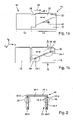
- figure 1 shows two side views of a first embodiment of a sensor housing 10 according to the invention, comprising a head part 12 with a sensor space for accommodating a sensor and a connection part 14 adjoining the head part 12 with a terminal space for Recording of a terminal block.
- connection part consists of a clamping space base 16 and a clamping space cover 18 which adjoin and enclose the clamping space and can be separated for access to the clamping space.
- a rear wall of the head part 12 adjoining the connection part 14 has a first through-opening and a side wall of the clamping space cover 18 adjoining the head part 12 has a second through-opening at least overlapping the first through-opening.
- a side wall of the lower part 16 of the clamping space has an entry opening for the cable and/or connector to be fed through from the outside into the clamping space.
- the head part 12 is connected to the clamping space cover 18 by means of a connecting means, which is also not shown.
- Terminal space cover 18 and terminal space base 16 are connected to one another by means of a plug connection 24 .
- the terminal compartment cover 18 comprises an inner part 20 and a cover part 22 that can be displaced relative to the inner part along a guide 30 along a locking direction 40 between an initial position (figure part (b)) and an end position (figure part (a)).
- Line AA is in figure 2 shown.
- the inner part 20 has a cover 20.1 and peripheral side walls 20.2.
- the cover part 22 is U-shaped and has a cover 22.1 and two opposite side walls 22.2 and encloses the cover 20.1 and two opposite side walls 20.2 of the inner part 20 at least in part.
- the guide 30 consists of a guide lug 22.3 arranged on an inner side of the side walls 22.2 of the cover part 22 and a guide groove 20.3 on an outer side of one of the enclosed side walls 20.2 of the inner part 20.
- the guide lug 22.3 and the guide groove 20.3 each extend parallel to the locking direction 40 along the respective side wall, with a guide groove 20.3 and a guide lug 22.3 lying opposite one another and engaging in one another.
- the plug-in connection 24 consists of at least a first connection part on the cover part 22 of the clamping space cover 18 and at least a second connection part on the clamping space lower part 16, with each first connection part being positively connected to the second connection part in the locking direction 40 or separated from the second connection part in the opposite direction to the locking direction 40 can be.
- two socket-like plug-in receptacles 24.1, e.g. cuboid bodies with a through bore or blind hole running parallel to the locking direction 40, are arranged on two opposite side walls of the clamping space lower part 16 as the second connecting parts.
- the cover part 22 of the clamping space cover 18 has four pins 24.2 as the first connecting parts, each pin 24.2 running parallel to the locking direction 40 and at a distance from an inside of the side wall 22.2 of the cover part 22 and being attached to the inside of the cover part 22 by means of a connecting piece .
- the connecting parts of the plug connection 24 are arranged in such a way that they engage in one another in the locking direction 40 .
- the four pins 24.2 of the cover part 22 of the clamping space cover 18 each engage in a form-fitting manner in a plug-in receptacle 24.1 of the clamping space base 16.
- the plug connection 24 is released or the plug-in receptacles 24.1 are spaced apart from the pins 24.2.
- connection part 14 has a locking device 26 for holding the cover part in the end position, in order to fix the cover part 22 in the end position relative to the inner part 20 of the clamping space cover 18 .
- the blocking device is designed according to a first embodiment as a pushbutton 26 arranged on the inner part 20 of the terminal compartment cover 18, the pushbutton being arranged in the end position of the cover part 22 along the locking direction 40 in front of the cover part 22 and one in the end position of the cover part 22 on the cover 22 adjacent holding surface 26.1.
- the push button is connected to a restoring means, e.g. a spring, so that the push button can be moved from a locked position by the application of force in an unlocking direction perpendicular to the locking direction 40 into an unlocked position and the push button can be moved by the restoring means into the locked position after the force has ended.
- a restoring means e.g. a spring
- figure 3 shows a top view of the sensor housing. In the following, only the differences to the figure 1 explained.
- the cover part 22 is in the final position.
- the end position is fixed by the push button 26.
- the clamping space lower part 16 has four through-holes 28 for fastening or as part of a fastening means.
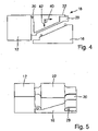
- FIG. 4 shows a side view of the sensor housing 10 with the terminal space open, i.e. the terminal space cover 18 separated from the terminal space base 16.
- the sensor housing 10 is shown in perspective in the closed state and with the cover part 22 in the end position.
Landscapes
- Physics & Mathematics (AREA)
- General Physics & Mathematics (AREA)
- Details Of Connecting Devices For Male And Female Coupling (AREA)
- Connector Housings Or Holding Contact Members (AREA)
Abstract
Description
- Die Erfindung betrifft ein Sensorgehäuse umfassend ein Kopfteil mit einem Sensorraum zur Aufnahme eines Sensors und ein Anschlussteil mit einem Klemmraum zur Aufnahme eines Klemmanschlussblocks gemäß dem Oberbegriff des Patentanspruchs 1.
- Aus der gattungsbildenden
EP 0 677 857 A1 ist ein elektrischer Schalter mit Tastkopf bekannt, dessen Schaltergehäuse aus einem Unterteil und einem durch Rastelemente lösbar mit demselben verbundenen Oberteil besteht. Auf dem Oberteil ist eine Deckel verrastbar, welcher an einem Ende schwenkbar auf dem Oberteil gelagert ist und an seinem anderen, freien Ende eine Rastelement trägt, für das auf dem Oberteil eine Gegenrastelement vorgesehen ist. - Eine typische Bauform von Sensoren, wie induktiven oder kapazitativen Näherungssensoren, umfasst ein zweiteiliges Gehäuse. Der Sensor ist in einem Kopfteil angeordnet und in einem Anschlussteil wird eine Kontaktiervorrichtung, z.B. ein Klemmanschlussblock, zum Anschließen eines von außen kommenden Kabels angeordnet. Das Anschlussteil bzw. der von dem Anschlussteil umfasste Raum wird daher häufig auch als Klemmraum bezeichnet.
- Der Sensor in dem Kopfteil ist durch elektrische Leitungen mit der Kontaktiervorrichtung verbunden, wofür das Kopfteil und das Anschlussteil entsprechende Durchgangsöffnungen und gegebenenfalls weitere Kontaktiervorrichtungen, wie z.B. Kontaktstifte, umfassen.
- Um einen Zugang zu dem Klemmraum zu ermöglichen besteht das Anschlussteil typischerweise aus einem Unterteil und einem Deckel, wobei das Unterteil typischerweise Befestigungsmittel, z.B. Durchgangsbohrungen für Schrauben, zur Befestigung an einer Oberfläche aufweist. Das Kopfteil ist typischerweise mit dem Deckel des Anschlussteils verbunden.
- Die Anschlussteildeckel des induktiven Näherungssensors NBB20-U1-UU oder des kapazitiven Sensors CJ15+U1+A2 der Fa. Pepperl + Fuchs GmbH werden jeweils mittels dreier Verbindungsschrauben mit dem Unterteil verbunden. Zwei der drei Schrauben dienen zusätzlich zur Fixierung des Kopfteils relativ zu dem Anschlussteil, indem die Schrauben in eine Nut eines von dem Kopfteil in das Anschlussteil hinein reichenden Verbindungsteils greifen.
- Auch die Standardbauform der Baureihe IQ40 der Fa. SICK AG, z.B. der induktive Näherungssensor IQ40-NPPKKOS weist ein durch Schrauben verschlossenes Anschlussteil auf.
- Der induktive Näherungssensor XS8C4A1PCG13 der zu der Fa. Schneider Electric SE gehörenden Marke Telemecanique Sensors weist einen mechanischen Riegel zur Fixierung des Kopfteils unabhängig von Verbindungsschrauben für das Anschlussteil auf. Unterteil und Deckel des Anschlussteils sind mittels dreier Schrauben miteinander verbunden.
- Von der Fa. Rockwell Automation, Inc. sind Näherungssensoren, z.B. das Modell 871L oder 872L DC, mit einem Kopfteil und einem Anschlussteil bekannt, wobei der Deckel des Anschlussteils eine Deckplatte aufweist, welches als Entriegelungshebel zum Entriegeln einer Verbindung zwischen Deckel und Boden des Anschlussteils dient. Der Entriegelungshebel muss mithilfe eines Werkzeugs gelöst werden.
- Des Weiteren beschreibt die
DE 28 19 782 A1 einen Näherungssensor mit einem Grundgehäuse, welches mit einem Messkopfteil verbunden ist. Das Grundgehäuse umfasst ein Unterteil und ein Oberteil, welche durch eine vertikale Relativbewegung zusammengefügt werden. Die Verbindung zwischen dem Unterteil und dem Oberteil erfolgt über Steckverbinder. - Ein Näherungssensor gemäß der
DE 81 04 480 U1 besteht aus einem topfförmigen Anschlussgehäuse mit einem daran befestigbaren Deckel sowie einem mit dem Anschlussgehäuse lösbar verbundenen Tastkopf. Der Tastkopf weist einen Stecker auf, so dass mit demselben die lösbare Verbindung mit dem Anschlussgehäuse herstellbar ist. - Schließlich ist auch aus der
US 6 635 833 B2 ein Näherungssensor mit einem einen Sensor aufnehmenden Kopfteil, welches an einem 2-teiligen Gehäuse angeordnet ist, bekannt. Das 2-teilige Gehäuse nimmt einen Klemmanschlussblock auf und besteht aus einem topfförmigen Grundgehäuse, welches mit einem haubenförmigen Deckel verschließbar ist. Stirnseitig des 2-teiligen Gehäuses bildet das Grundgehäuse zusammen mit dem haubenförmigen Deckel eine fluiddichte Durchgangsöffnung zur Durchführung eines Anschlusskabels. - Vor diesem Hintergrund besteht die Aufgabe der Erfindung darin, eine Vorrichtung anzugeben, die den Stand der Technik weiterbildet.
- Insbesondere soll ein Sensorgehäuse mit einem einfachen, intuitiv zugänglichen und werkzeuglos bedienbaren Mechanismus für die Verbindung zwischen dem Deckel und Unterteil des Anschlussteils bereitgestellt werden.
- Die Aufgabe wird durch eine Vorrichtung mit den Merkmalen des Patentanspruchs 1 gelöst. Vorteilhafte Ausgestaltungen der Erfindung sind Gegenstand von Unteransprüchen.
- Gemäß dem Gegenstand der Erfindung wird ein Sensorgehäuse bereitgestellt, umfassend ein Kopfteil mit einem Sensorraum zur Aufnahme eines Sensors und ein an das Kopfteil angrenzendes Anschlussteil mit einem Klemmraum zur Aufnahme eines Klemmanschlussblocks.
- Das Kopfteil weist in einer an das Anschlussteil angrenzenden Rückwand eine Durchgangsöffnung zur Kabel- und/oder Steckerdurchführung in den Sensorraum auf. Das Anschlussteil umfasst ein Klemmraumunterteil und einen Klemmraumdeckel auf, wobei das Klemmraumunterteil und der Klemmraumdeckel entlang einer Schließrichtung zusammengesetzt sind, so dass das Klemmraumunterteil und der Klemmraumdeckel den Klemmraum umschließen.
- Der Klemmraumdeckel oder das Klemmraumunterteil ist mittels eines Verbindungsmittels mit dem Kopfteil verbunden und weist eine an die Rückwand des Kopfteils angrenzende Seitenwand mit einer mit der Durchgangsöffnung des Kopfteils zumindest überlappenden Durchgangsöffnung zur Kabel- und/oder Steckerdurchführung von dem Sensorraum in den Klemmraum auf.
- Das Klemmraumunterteil oder der Klemmraumdeckel weist eine Seitenwand mit einer Eingangsöffnung zur Kabel- und/oder Steckerdurchführung auf.
- Das Klemmraumunterteil weist mindestens ein erstes Verbindungsteil einer in einer Verriegelungsrichtung ineinandergreifenden Steckverbindung auf.
- Der Klemmraumdeckel umfasst ein Innenteil und ein Abdeckteil, wobei das Innenteil eine Führung aufweist und das Abdeckteil mindestens ein zweites Verbindungsteil der in der Verriegelungsrichtung ineinandergreifenden Steckverbindung aufweist.
- Das Abdeckteil ist gegenüber dem Innenteil entlang einer Führung entlang der Verriegelungsrichtung zwischen einer Anfangsposition und einer Endposition verschiebbar ausgebildet, wobei das Abdeckteil das Innenteil zumindest in der Endposition teilweise überdeckt.
- Bei auf dem Klemmraumunterteil aufgesetztem Klemmraumdeckels greifen das erste Verbindungsteil und das zweite Verbindungsteil der Steckverbindung in der Endposition ineinander, während das erste Verbindungsteil und das zweite Verbindungsteil der Steckverbindung in der Anfangsposition des Abdeckteils zueinander beabstandet sind.
- Es versteht sich, dass die Begriffe Klemmraumunterteil und Klemmraumdeckel keine Ausrichtung des Anschlussteils bzw. keine Position/Ausrichtung der beiden Teile des Anschlussteils vorgeben. Die Begriffe dienen lediglich zur Unterscheidung bzw. zur Kennzeichnung der beiden Teile des zweiteiligen Anschlussteils.
- Außerdem umschließen der Klemmraumdeckel und das Klemmraumunterteil den Klemmraum offensichtlich nicht vollständig bzw. nur soweit, dass die Eingangsöffnung sowie die Durchgangsöffnung zur Kabel- und/oder Steckerdurchführung in den Klemmraum offen bleiben.
- Die einfachste Form für das Anschlussteil ist ein Quader mit einem Boden, einer Decke und vier Seitenwänden, wobei das Klemmraumunterteil den Boden und jeweils einen Teil jeder Seitenwand und der Klemmraumdeckel die Decke und jeweils den restlichen Teil jeder Seitenwand umfasst.
- Ebenso ist es möglich, dass eine Seitenwand des Anschlussteils vollständig von dem Klemmraumdeckel oder vollständig von dem Klemmraumunterteil umfasst wird, so dass diese Seitenwand im zusammengesetzten Zustand direkt an den Boden bzw. die Decke des Gegenstücks angrenzt.
- Es versteht sich auch, dass der Klemmblock sowohl als separates Bauteil oder auch einstückig mit dem Anschlussteil, also mit dem Klemmraumunterteil oder auch dem Innenteil des Klemmraumdeckels, ausgebildet sein kann.
- Die Verriegelungsrichtung verläuft von der Anfangsposition in Richtung der Endposition. Zum Entriegeln wird das Abdeckteil entsprechend entgegen der Verriegelungsrichtung bewegt und die Steckverbindung hierdurch gelöst, so dass Klemmraumdeckel und Klemmraumunterteil entgegen der Schließrichtung voneinander getrennt werden können.
- Das Abdeckteil dient der Verbindung von Klemmraumunterteil und Klemmraumdeckel bzw. zur Ent- bzw. Verriegelung der beiden Teile. Hierfür ist das Abdeckteil an dem Innenteil so angeordnet, dass es von außen gegriffen und entlang der Verriegelungsrichtung, also zumindest innerhalb der Anfangsposition und der Endposition sowohl in Verriegelungsrichtung als auch entgegen der Verriegelungsrichtung, durch die Führung geführt verschoben werden kann.
- Es versteht sich, dass die beiden Verbindungsteile der Steckverbindung entlang der Verriegelungsrichtung ineinander fügbar sind, so dass die beiden Verbindungsteile in der Endposition formschlüssig ineinandergreifen. Durch den Formschluss wird eine Bewegung senkrecht zu der Verriegelungsrichtung verhindert. Ein Lösen der Steckverbindung ist nur durch Trennen der beiden Verbindungsteile durch eine entgegen der Verriegelungsrichtung gerichtete Bewegung möglich.
- Die Steckverbindung umfasst beispielsweise einen Stift als erstes oder zweites Verbindungsteil und eine entsprechende Ausnehmung als zweites bzw. erstes Verbindungsteil.
- Durch die Verbindung des Kopfteils mit dem Klemmraumdeckel oder des Klemmraumunterteils mittels des Verbindungmittels bzw. die Befestigung des Kopfteils an einem der Teile des Anschlussteils verbleibt das Kopfteil beim Öffnen des Klemmraums an dem Klemmraumdeckel bzw. Klemmraumunterteil. Die Verbindung des Kopfteils mit dem Anschlussteil ist dadurch unabhängig von der Verbindung zwischen Klemmraumunterteil und Klemmraumdeckel. Es wird sichergestellt, dass das Kopfteil beim Öffnen des Klemmraums nicht herunterfallen kann. Unnötiger Stress oder Zug auf die von dem Klemmraum in den Sensorraum verlaufenden Kabel und/oder Stecker wird vermieden. Andererseits kann das Kopfteil zusammen mit dem entsprechenden Teil des Anschlussteils auf einfache Weise werkzeuglos abgenommen werden, beispielsweise um eine Ausrichtung des Kopfteils gegenüber dem Anschlussteil zu ändern.
- Das erfindungsgemäße Sensorgehäuse ermöglicht einen einfachen, schnellen und werkzeuglosen Zugang zu dem Klemmraum bzw. ein einfaches, werkzeugloses Abnehmen des Kopfteils zusammen mit dem Klemmraumdeckel.
- Insbesondere ist keine Schraubverbindung notwendig, welches das Mitführen eines Werkzeugs voraussetzt, zeitaufwändiger ist und häufig metallische und damit elektrisch leitfähige Teile umfasst. Das erfindungsgemäße Sensorgehäuse kann aus einem einzigen Material gefertigt werden, z.B. einem Kunststoff und ist dadurch besonders einfach und Kostengünstig herstellbar.
- Gemäß einer ersten Ausführungsform umfasst das Anschlussteil mindestens zwei Steckverbindungen, wobei das Abdeckteil des Klemmraumdeckels zwei einander gegenüberliegende und zur Verriegelungsrichtung parallel verlaufende Seitenwände mit jeweils mindestens einem zweiten Verbindungsteilen der mindestens zwei Steckverbindungen aufweist.
- In einer besonders stabilen Weiterbildung weist das Anschlussteil mindestens vier Steckverbindungen auf.
- Gemäß einer weiteren Weiterbildung weist das Klemmraumunterteil und/oder der Klemmraumdeckel mindestens eine Sperrvorrichtung zum Festhalten des Abdeckteils in der Endstellung auf. Die Sperrvorrichtung ist entweder vollständig an dem Klemmraumunterteil oder vollständig an dem Klemmraumdeckel angeordnet oder es sind jeweils Teile der Sperrvorrichtung an dem Klemmraumunterteil und an dem Klemmraumdeckel angeordnet.
- Gemäß einer ersten Ausführungsform umfasst die Sperrvorrichtung eine Drucktaste und ein Rückstellmittel, wobei die Drucktaste von einer Verriegelungsstellung durch Krafteinwirkung in einer senkrecht zu der Verriegelungsrichtung verlaufenden Entsperrrichtung in eine Entsperrstellung bewegbar ist. Die Drucktaste ist nach einem Ende der Krafteinwirkung durch das Rückstellmittel in die Sperrstellung bewegbar.
- In einer Weiterbildung ist die Drucktaste an dem Innenteil des Klemmraumdeckels oder an dem Abdeckteil des Klemmraumdeckels angeordnet, wobei das Rückstellmittel an dem Innenteil oder an dem Abdeckteil angeordnet ist. Gemäß einer weiteren Weiterbildung ist die Drucktaste in der Endposition des Abdeckteils in der Verriegelungsrichtung zumindest teilweise vor dem Abdeckteil angeordnet und weist eine in der Endposition des Abdeckteils an das Abdeckteil angrenzende Haltefläche auf. So wird eine einfache Fixierung/Sicherung der Verbindung zwischen Klemmraumdeckel und Klemmraumunterteil bereitgestellt, die werkzeuglos bedienbar ist.
- Gemäß einer anderen Ausführungsform verläuft eine Fügefläche zwischen mindestens einer parallel zu der Verriegelungsrichtung verlaufenden Seitenwand des Klemmraumunterteils und mindestens einer parallel zu der Verriegelungsrichtung verlaufenden Seitenwand des Klemmraumdeckels zumindest teilweise parallel zu der Verriegelungsrichtung und/oder zumindest teilweise unter einem Winkel zu der Verriegelungsrichtung.
- Gemäß einer weiteren Ausführungsform schließt die Schließrichtung mit der Verriegelungsrichtung einen Winkel von mindestens 0° oder mindestens 15° oder mindestens 30° und von höchstens 90° ein.
- In einer anderen Weiterbildung entspricht das Sensorgehäuse dem IP 68 Standard oder dem IP 69K Standard.
- In einer weiteren Weiterbildung weist das Klemmraumunterteil und/oder der Klemmraumdeckel mindestens ein Befestigungsmittel oder zumindest einen Teil eines Befestigungsmittels zur Befestigung des Sensorgehäuses an einer Oberfläche auf.
- Gemäß einer anderen Ausführungsform weist das Abdeckteil des Klemmraumdeckels in einer senkrecht zu der Verriegelungsrichtung verlaufenden Ebene einen U-förmig Verlauf auf.
- Gemäß einer weiteren Ausführungsform besteht das Sensorgehäuse vollständig aus einem oder mehreren nicht elektrisch leitfähigen Materialien, z.B. aus einem Kunststoff oder aus mehreren unterschiedlichen Kunststoffen.
- In einer Weiterbildung wird ein induktiver oder kapazitiver Näherungssensor bereitgestellt, wobei der Näherungssensor ein Sensorgehäuse der vorbeschriebenen Art aufweist.
- Die Erfindung wird nachfolgend unter Bezugnahme auf die Zeichnungen näher erläutert. Hierbei werden gleichartige Teile mit identischen Bezeichnungen beschriftet. Die dargestellten Ausführungsformen sind stark schematisiert, d.h. die Abstände und die lateralen und die vertikalen Erstreckungen sind nicht maßstäblich und weisen, sofern nicht anders angegeben, auch keine ableitbaren geometrischen Relationen zueinander auf. Darin zeigten, die
- Figur 1
- eine seitliche Ansicht einer ersten erfindungsgemäße Aus-führungsform eines Sensorgehäuses,
- Figur 2
- eine Schnittansicht entlang AA eines Klemmraumdeckels gemäß der ersten erfindungsgemäßen Ausführungsform,
- Figur 3
- eine Aufsicht auf die erste erfindungsgemäße Ausfüh-rungsform des Sensorgehäuses,
- Figur 4
- eine seitliche Ansicht eines geöffneten Sensorgehäuses gemäß der ersten Ausführungsform,
- Figur 5
- eine perspektivische Ansicht der ersten erfindungsgemäßen Ausführungsform des Sensorgehäuses.
- Die Abbildung der
Figur 1 zeigt zwei seitliche Ansichten einer ersten erfindungsgemäßen Ausführungsform eines Sensorgehäuse 10, umfassend ein Kopfteil 12 mit einem Sensorraum zur Aufnahme eines Sensors und ein an das Kopfteil 12 angrenzendes Anschlussteil 14 mit einem Klemmraum zur Aufnahme eines Klemmanschlussblocks. - Das Anschlussteil besteht aus einem Klemmraumunterteil 16 und einem Klemmraumdeckel 18, die aneinander angrenzen und den Klemmraum umschließen und für einen Zugang zu dem Klemmraum getrennt werden können.
- Nicht dargestellt sind die Durchgangsöffnungen für die Kabel- und/oder Steckerdurchführung zwischen dem Sensorraum und dem Klemmraum bzw. in den Klemmraum. Hierfür weist eine an das Anschlussteil 14 angrenzende Rückwand des Kopfteils 12 eine erste Durchgangsöffnung und eine an das Kopfteil 12 angrenzenden Seitenwand des Klemmraumdeckels 18 eine mit der ersten Durchgangsöffnung zumindest überlappende zweite Durchgangsöffnung auf.
- Außerdem weist eine Seitenwand des Klemmraumunterteils 16 eine Eingangsöffnung zur Kabel- und/oder Steckerdurchführung von außen in den Klemmraum auf.
- Das Kopfteil 12 ist mittels eines ebenfalls nicht dargestellten Verbindungsmittels mit dem Klemmraumdeckel 18 verbunden.
- Klemmraumdeckel 18 und Klemmraumunterteil 16 sind mittels einer Steckverbindung 24 miteinander verbunden. Hierfür umfasst der Klemmraumdeckel 18 ein Innenteil 20 und ein gegenüber dem Innenteil entlang einer Führung 30 entlang einer Verriegelungsrichtung 40 zwischen einer Anfangsposition (Abbildungsteil (b)) und einer Endposition (Abbildungsteil (a)) verschiebbares Abdeckteil 22. Ein Querschnitt des Klemmraumdeckels 18 entlang der Linie AA ist in
Figur 2 dargestellt. - Das Innenteil 20 weist eine Decke 20.1 und umlaufende Seitenwänden 20.2 auf. Das Abdeckteil 22 ist u-förmig und weist eine Decke 22.1 und zwei einander gegenüberliegende Seitenwände 22.2 auf und umschließt die Decke 20.1 sowie zwei einander gegenüberliegende Seitenwände 20.2 des Innenteils 20 zumindest teilweise.
- Die Führung 30 besteht aus jeweils einer an einer Innenseite der Seitenwände 22.2 des Abdeckteils 22 angeordneten Führungsnase 22.3 und je einer Führungsnut 20.3 an einer Außenseiten einer der umschlossenen Seitenwände 20.2 des Innenteils 20. Die Führungsnase 22.3 und die Führungsnut 20.3 erstrecken sich jeweils parallel zu der Verriegelungsrichtung 40 entlang der jeweiligen Seitenwand, wobei jeweils eine Führungsnut 20.3 und eine Führungsnase 22.3 einander gegenüberliegen und ineinander greifen.
- Die Steckverbindung 24 besteht aus mindestens einem ersten Verbindungsteil an dem Abdeckteil 22 des Klemmraumdeckels 18 und mindestens einem zweiten Verbindungsteil an dem Klemmraumunterteil 16, wobei jedes erste Verbindungsteil in Verriegelungsrichtung 40 mit dem zweiten Verbindungsteil formschlüssig verbunden bzw. entgegen der Verriegelungsrichtung 40 von dem zweiten Verbindungsteil getrennt werden kann.
- In dem dargestellten Ausführungsbeispiel sind als zweite Verbindungsteile jeweils zwei buchsenartige Steckaufnahmen 24.1, z.B. quaderförmige Körper mit parallel zu der Verriegelungsrichtung 40 verlaufender Durchgangsbohrung oder Sackloch, an zwei einander gegenüberliegenden Seitenwänden des Klemmraumunterteils 16 angeordnet. Als erste Verbindungsteile weist das Abdeckteil 22 des Klemmraumdeckels 18 vier Stifte 24.2 auf, wobei jeder Stift 24.2 parallel zu der Verriegelungsrichtung 40 und in einem Abstand zu einer Innenseite der Seitenwand 22.2 des Abdeckteils 22 verläuft und mittels eines Verbindungsstücks an der Innenseite des Abdeckteils 22 angebracht ist.
- Die Verbindungsteile der Steckverbindung 24 sind so angeordnet, dass sie in Verriegelungsrichtung 40 ineinandergreifen. In der Endposition (Abbildungsteil (a) der
Figur 1 ) greifen die vier Stifte 24.2 des Abdeckteils 22 des Klemmraumdeckels 18 jeweils formschlüssig in eine Steckaufnahme 24.1 des Klemmraumunterteils 16. In der Anfangsposition (Abbildungsteil (b) derFigur 1 ) ist die Steckverbindung 24 gelöst bzw. sind die Steckaufnahmen 24.1 zu den Stiften 24.2 beabstandet. - Es versteht sich, dass es ebenso möglich ist, die Stifte an dem Klemmraumunterteil 16 und die Steckaufnahmen 24.1 an dem Abdeckteil 22 des Klemmraumdeckels 18 anzuordnen.
- Gemäß einer Weiterbildung weist das Anschlussteil 14 eine Sperrvorrichtung 26 zum Festhalten des Abdeckteils in der Endstellung auf, um das Abdeckteil 22 relativ zu dem Innenteil 20 des Klemmraumdeckels 18 in der Endposition zu fixieren. Wie in dem Abbildungsteil (a) der
Figur 1 gestrichelt dargestellt, ist die Sperrvorrichtung gemäß einer ersten Ausführungsform als an dem Innenteil 20 des Klemmraumdeckels 18 angeordnete Drucktaste 26 ausgebildet, wobei die Drucktaste in der Endposition des Abdeckteils 22 entlang der Verriegelungsrichtung 40 vor dem Abdeckteil 22 angeordnet ist und eine in der Endposition des Abdeckteils 22 an das Abdeckteil 22 angrenzende Haltefläche 26.1 aufweist. - Die Drucktaste ist mit einem Rückstellmittel verbunden, z.B. einer Feder, so dass die Drucktaste von einer Sperrstellung durch Krafteinwirkung in einer senkrecht zu der Verriegelungsrichtung 40 verlaufenden Entsperrrichtung in eine Entsperrstellung und die Drucktaste nach einem Ende der Krafteinwirkung durch den Rückstellmittel in die Sperrstellung bewegbar ist.
- In der Abbildung der
Figur 3 ist eine Aufsicht auf das Sensorgehäuse dargestellt. Im Folgenden werden jeweils nur die Unterschiede zu derFigur 1 erläutert. - In Abbildungsteil (a) befindet sich das Abdeckteil 22 in der Endposition. Die Endposition ist durch die Drucktaste 26 fixiert. Das Klemmraumunterteil 16 weist vier Durchgangsbohrungen 28 zur Befestigung bzw. als Teil eines Befestigungsmittels auf.
- In Abbildungsteil (b) befindet sich das Abdeckteil 22 in der Anfangsposition. Die Drucktaste 26 befindet sich in der Entriegelungsstellung und ist in der dargestellten Aufsicht vollständig von dem Abdeckteil 22 verdeckt.
- Die Abbildung der
Figur 4 zeigt eine seitliche Ansicht des Sensorgehäuses 10 mit geöffnetem Klemmraum, also von dem Klemmraumunterteil 16 getrenntem Klemmraumdeckel 18. - In der Abbildung der
Figur 5 ist das Sensorgehäuse 10 in geschlossenem Zustand und mit dem Abdeckteil 22 in der Endposition perspektivisch dargestellt.
Claims (13)
- Sensorgehäuse (10), umfassend ein Kopfteil (12) mit einem Sensorraum zur Aufnahme eines Sensors und ein an das Kopfteil (12) angrenzendes Anschlussteil (14) mit einem Klemmraum zur Aufnahme eines Klemmanschlussblocks, wobei- das Kopfteil (12) in einer an das Anschlussteil (14) angrenzenden Rückwand eine Durchgangsöffnung zur Kabel- und/oder Steckerdurchführung in den Sensorraum aufweist,- das Anschlussteil (14) ein Klemmraumunterteil (16) und einen Klemmraumdeckel (18) umfasst,- das Klemmraumunterteil (16) und der Klemmraumdeckel (18) in einer Schließrichtung (42) zusammengesetzt sind, so dass- das Klemmraumunterteil (16) und der Klemmraumdeckel (18) den Klemmraum umschließen,- der Klemmraumdeckel (18) oder das Klemmraumunterteil (16) mittels eines Verbindungsmittels mit dem Kopfteil (12) verbunden ist und eine an die Rückwand des Kopfteils (12) angrenzende Seitenwand mit einer mit der Durchgangsöffnung des Kopfteils (12) zumindest überlappenden Durchgangsöffnung zur Kabel- und/oder Steckerdurchführung von dem Sensorraum in den Klemmraum aufweist,- das Klemmraumunterteil (16) oder der Klemmraumdeckel (18) eine Seitenwand mit einer Eingangsöffnung zur Kabel- und/oder Steckerdurchführung aufweist,
dadurch gekennzeichnet, dass- das Klemmraumunterteil (16) mindestens ein erstes Verbindungsteil (24.1) einer in einer Verriegelungsrichtung (40) ineinandergreifenden Steckverbindung (24) aufweist- der Klemmraumdeckel (18) ein Innenteil (20) mit einer Führung (30) und ein Abdeckteil (22) mit mindestens einem zweiten Verbindungsteil (24.2) der in der Verriegelungsrichtung (40) ineinandergreifenden Steckverbindung (24) aufweist,- das Abdeckteil (22) gegenüber dem Innenteil (20) entlang der Führung (30) entlang der Verriegelungsrichtung (40) zwischen einer Anfangsposition und einer Endposition verschiebbar ausgebildet ist,- das Abdeckteil (22) das Innenteil (20) zumindest in der Endposition teilweise überdeckt und- bei auf dem Klemmraumunterteil (16) aufgesetztem Klemmraumdeckel (18) das erste Verbindungsteil (24.1) und das zweite Verbindungsteil (24.2) der Steckverbindung (24) in der Endposition des Abdeckteils (22) ineinander greifen und in der Anfangsposition des Abdeckteils (22) zueinander beabstandet sind. - Sensorgehäuse (10) nach Anspruch 1, dadurch gekennzeichnet, dass das Anschlussteil (14) mindestens zwei Steckverbindungen (24) umfasst, wobei das Abdeckteil (22) des Klemmraumdeckels (18) zwei einander gegenüberliegende und zur Verriegelungsrichtung (40) parallel verlaufende Seitenwände mit jeweils mindestens einem zweiten Verbindungsteil (24.2) der mindestens zwei Steckverbindungen (24) aufweist.
- Sensorgehäuse (10) nach einem der vorangegangenen Ansprüche, dadurch gekennzeichnet, dass das Klemmraumunterteil (16) und/oder der Klemmraumdeckel (18) mindestens eine Sperrvorrichtung (26) zum Festhalten des Abdeckteils (22) in der Endstellung aufweisen.
- Sensorgehäuse (10) nach Anspruch 3, dadurch gekennzeichnet, dass die Sperrvorrichtung (26) eine Drucktaste und ein Rückstellmittel umfasst, wobei die Drucktaste von einer Sperrstellung durch Krafteinwirkung in einer senkrecht zu der Verriegelungsrichtung (40) verlaufenden Entsperrrichtung in eine Entsperrstellung bewegbar ist und die Drucktaste nach einem Ende der Krafteinwirkung durch das Rückstellmittel in die Sperrstellung bewegbar ist.
- Sensorgehäuse (10) nach Anspruch 4, dadurch gekennzeichnet, dass die Drucktaste an dem Innenteil (20) des Klemmraumdeckels (18) oder an dem Abdeckteil (22) des Klemmraumdeckels (18) angeordnet ist, wobei das Rückstellmittel an dem Innenteil (20) oder an dem Abdeckteil (22) angeordnet ist.
- Sensorgehäuse (10) nach Anspruch 4 oder 5, dadurch gekennzeichnet, dass die Drucktaste in der Endposition des Abdeckteils (22) in der Verriegelungsrichtung (40) zumindest teilweise vor dem Abdeckteil (22) angeordnet ist und die Drucktaste eine in der Endposition des Abdeckteils (22) an das Abdeckteil (22) angrenzende Haltefläche (26.1) aufweist.
- Sensorgehäuse (10) nach einem der vorangegangenen Ansprüche, dadurch gekennzeichnet, dass eine Fügefläche zwischen mindestens einer parallel zu der Verriegelungsrichtung (40) verlaufenden Seitenwand des Klemmraumunterteils (16) und mindestens einer parallel zu der Verriegelungsrichtung (40) verlaufenden Seitenwand des Klemmraumdeckels (18) zumindest teilweise parallel zu der Verriegelungsrichtung (40) verläuft und/oder zumindest teilweise unter einem Winkel (α) zu der Verriegelungsrichtung (40) verläuft.
- Sensorgehäuse (10) nach einem der vorangegangenen Ansprüche, dadurch gekennzeichnet, dass die Schließrichtung (42) mit der Verriegelungsrichtung (40) einen Winkel (β) von mindestens 0° oder mindestens 15° oder mindestens 30° und von höchstens 90° einschließt.
- Sensorgehäuse (10) nach einem der vorangegangenen Ansprüche, dadurch gekennzeichnet, dass das Sensorgehäuse (10) dem IP 68 Standard oder dem IP 69K Standard entspricht.
- Sensorgehäuse (10) nach einem der vorangegangenen Ansprüche, dadurch gekennzeichnet, dass das Klemmraumunterteil (16) und/oder der Klemmraumdeckel (18) mindestens ein Befestigungsmittel (28) oder zumindest einen Teil eines Befestigungsmittels (28) zur Befestigung des Sensorgehäuses (10) an einer Oberfläche aufweisen.
- Sensorgehäuse (10) nach einem der vorangegangenen Ansprüche, dadurch gekennzeichnet, dass das Abdeckteil (22) des Klemmraumdeckels (18) in einer senkrecht zu der Verriegelungsrichtung (40) verlaufenden Ebene einen U-förmig Verlauf aufweist.
- Sensorgehäuse (10) nach einem der vorangegangenen Ansprüche, dadurch gekennzeichnet, dass das Sensorgehäuse vollständig aus einem oder mehreren nicht elektrisch leitfähigen Materialien besteht.
- Induktiver Näherungssensor oder kapazitiver Näherungssensor, dadurch gekennzeichnet, dass der Näherungssensor ein Sensorgehäuse (10) gemäß einem der vorangegangenen Ansprüche aufweist.
Applications Claiming Priority (1)
| Application Number | Priority Date | Filing Date | Title |
|---|---|---|---|
| DE102021002336.6A DE102021002336B3 (de) | 2021-05-04 | 2021-05-04 | Sensorgehäuse |
Publications (2)
| Publication Number | Publication Date |
|---|---|
| EP4086590A1 true EP4086590A1 (de) | 2022-11-09 |
| EP4086590B1 EP4086590B1 (de) | 2023-06-14 |
Family
ID=81580332
Family Applications (1)
| Application Number | Title | Priority Date | Filing Date |
|---|---|---|---|
| EP22000118.4A Active EP4086590B1 (de) | 2021-05-04 | 2022-05-02 | Sensorgehäuse |
Country Status (2)
| Country | Link |
|---|---|
| EP (1) | EP4086590B1 (de) |
| DE (1) | DE102021002336B3 (de) |
Citations (6)
| Publication number | Priority date | Publication date | Assignee | Title |
|---|---|---|---|---|
| DE2819782A1 (de) | 1978-05-05 | 1979-11-08 | Pepperl & Fuchs | Naeherungsinitiator |
| DE8104480U1 (de) | 1981-02-18 | 1981-06-19 | Pulsotronic Merten Gmbh & Co Kg, 5270 Gummersbach | Beruehrunglos wirkender endschalter |
| DE3324242A1 (de) * | 1983-07-06 | 1985-01-17 | Zwicker + Hensel Elektronische Schalttechnik GmbH, 5960 Olpe | Naeherungsschaltgeraet |
| DE4412923C1 (de) * | 1994-04-15 | 1995-08-31 | Bernstein Senso Plus Gmbh | Elektrischer Schalter mit Tastkopf |
| EP0998042A2 (de) * | 1998-10-20 | 2000-05-03 | Siemens Aktiengesellschaft | Berührungslos arbeitendes Schaltgerät mit einem Sensorkopf |
| US6635833B2 (en) | 2001-02-07 | 2003-10-21 | Schneider Electric Industries Sa | Limit switch |
-
2021
- 2021-05-04 DE DE102021002336.6A patent/DE102021002336B3/de active Active
-
2022
- 2022-05-02 EP EP22000118.4A patent/EP4086590B1/de active Active
Patent Citations (7)
| Publication number | Priority date | Publication date | Assignee | Title |
|---|---|---|---|---|
| DE2819782A1 (de) | 1978-05-05 | 1979-11-08 | Pepperl & Fuchs | Naeherungsinitiator |
| DE8104480U1 (de) | 1981-02-18 | 1981-06-19 | Pulsotronic Merten Gmbh & Co Kg, 5270 Gummersbach | Beruehrunglos wirkender endschalter |
| DE3324242A1 (de) * | 1983-07-06 | 1985-01-17 | Zwicker + Hensel Elektronische Schalttechnik GmbH, 5960 Olpe | Naeherungsschaltgeraet |
| DE4412923C1 (de) * | 1994-04-15 | 1995-08-31 | Bernstein Senso Plus Gmbh | Elektrischer Schalter mit Tastkopf |
| EP0677857A1 (de) | 1994-04-15 | 1995-10-18 | Bernstein Senso-Plus GmbH | Elektrischer Schalter mit Tastkopf |
| EP0998042A2 (de) * | 1998-10-20 | 2000-05-03 | Siemens Aktiengesellschaft | Berührungslos arbeitendes Schaltgerät mit einem Sensorkopf |
| US6635833B2 (en) | 2001-02-07 | 2003-10-21 | Schneider Electric Industries Sa | Limit switch |
Also Published As
| Publication number | Publication date |
|---|---|
| EP4086590B1 (de) | 2023-06-14 |
| DE102021002336B3 (de) | 2022-08-18 |
Similar Documents
| Publication | Publication Date | Title |
|---|---|---|
| EP1189307B1 (de) | Elektrische Reihenklemme | |
| DE112008002986B4 (de) | Verbinder für eine Verwendung mit einem Gerät | |
| DE69016717T2 (de) | Einbauverbinder für Kabelanordnung. | |
| DE19738772B4 (de) | Steckvorrichtung | |
| EP1131860B1 (de) | Kontaktierungsvorrichtung für ein flachbandkabel | |
| AT523016B1 (de) | Steckverbinder | |
| WO2024008226A1 (de) | Kraftfahrzeugschloss | |
| EP2060161B1 (de) | Transportgehäuse für eine elektronische flachbaugruppe | |
| EP3073577B1 (de) | Steckerteil, steckverbindung und verfahren zum herstellen eines steckerteils | |
| DE3743865A1 (de) | Telekommunikationsgeraet, insbesondere fernsprech-nebenstellenanlage | |
| DE10044791A1 (de) | Anbaugehäuse | |
| EP4086590B1 (de) | Sensorgehäuse | |
| DE19961370A1 (de) | Türaußengriffanordnung für eine Kraftfahrzeugtür, Kraftfahrzeugtür und Verfahren zur Montage eines Türaußengriffs | |
| DE19751024A1 (de) | Defibrillator | |
| EP4086588B1 (de) | Sensorgehäuse | |
| DE102024113754B3 (de) | Messgerät zur Messung elektrischer Größen | |
| EP4150718A1 (de) | Isolierkörper für schraub- und crimpkontakte | |
| EP0677857B1 (de) | Elektrischer Schalter mit Tastkopf | |
| EP1032005B1 (de) | Elektrische Anlage | |
| EP0707293A1 (de) | Gehäuse für eine Überwachungseinrichtung | |
| DE102024113752A1 (de) | Messgerät zur Messung elektrischer Größen | |
| DE102024113750A1 (de) | Messgerät zur Messung elektrischer Größen | |
| DE102024113756A1 (de) | Messgerät zur Messung elektrischer Größen | |
| DE3209823C2 (de) | Steckdose, insbesondere Anbausteckdose, für Rundsteckvorrichtungen | |
| DE19845335A1 (de) | Geräteaufnahme für eine Unterflurgerätedose |
Legal Events
| Date | Code | Title | Description |
|---|---|---|---|
| PUAI | Public reference made under article 153(3) epc to a published international application that has entered the european phase |
Free format text: ORIGINAL CODE: 0009012 |
|
| STAA | Information on the status of an ep patent application or granted ep patent |
Free format text: STATUS: THE APPLICATION HAS BEEN PUBLISHED |
|
| STAA | Information on the status of an ep patent application or granted ep patent |
Free format text: STATUS: REQUEST FOR EXAMINATION WAS MADE |
|
| AK | Designated contracting states |
Kind code of ref document: A1 Designated state(s): AL AT BE BG CH CY CZ DE DK EE ES FI FR GB GR HR HU IE IS IT LI LT LU LV MC MK MT NL NO PL PT RO RS SE SI SK SM TR |
|
| 17P | Request for examination filed |
Effective date: 20221017 |
|
| RBV | Designated contracting states (corrected) |
Designated state(s): AL AT BE BG CH CY CZ DE DK EE ES FI FR GB GR HR HU IE IS IT LI LT LU LV MC MK MT NL NO PL PT RO RS SE SI SK SM TR |
|
| GRAP | Despatch of communication of intention to grant a patent |
Free format text: ORIGINAL CODE: EPIDOSNIGR1 |
|
| STAA | Information on the status of an ep patent application or granted ep patent |
Free format text: STATUS: GRANT OF PATENT IS INTENDED |
|
| RIC1 | Information provided on ipc code assigned before grant |
Ipc: H03K 17/95 20060101ALI20230210BHEP Ipc: G01D 11/24 20060101AFI20230210BHEP |
|
| INTG | Intention to grant announced |
Effective date: 20230301 |
|
| GRAS | Grant fee paid |
Free format text: ORIGINAL CODE: EPIDOSNIGR3 |
|
| GRAA | (expected) grant |
Free format text: ORIGINAL CODE: 0009210 |
|
| STAA | Information on the status of an ep patent application or granted ep patent |
Free format text: STATUS: THE PATENT HAS BEEN GRANTED |
|
| AK | Designated contracting states |
Kind code of ref document: B1 Designated state(s): AL AT BE BG CH CY CZ DE DK EE ES FI FR GB GR HR HU IE IS IT LI LT LU LV MC MK MT NL NO PL PT RO RS SE SI SK SM TR |
|
| REG | Reference to a national code |
Ref country code: CH Ref legal event code: EP |
|
| REG | Reference to a national code |
Ref country code: DE Ref legal event code: R096 Ref document number: 502022000033 Country of ref document: DE |
|
| REG | Reference to a national code |
Ref country code: AT Ref legal event code: REF Ref document number: 1579530 Country of ref document: AT Kind code of ref document: T Effective date: 20230715 |
|
| REG | Reference to a national code |
Ref country code: LT Ref legal event code: MG9D |
|
| REG | Reference to a national code |
Ref country code: NL Ref legal event code: MP Effective date: 20230614 |
|
| PG25 | Lapsed in a contracting state [announced via postgrant information from national office to epo] |
Ref country code: SE Free format text: LAPSE BECAUSE OF FAILURE TO SUBMIT A TRANSLATION OF THE DESCRIPTION OR TO PAY THE FEE WITHIN THE PRESCRIBED TIME-LIMIT Effective date: 20230614 Ref country code: NO Free format text: LAPSE BECAUSE OF FAILURE TO SUBMIT A TRANSLATION OF THE DESCRIPTION OR TO PAY THE FEE WITHIN THE PRESCRIBED TIME-LIMIT Effective date: 20230914 Ref country code: ES Free format text: LAPSE BECAUSE OF FAILURE TO SUBMIT A TRANSLATION OF THE DESCRIPTION OR TO PAY THE FEE WITHIN THE PRESCRIBED TIME-LIMIT Effective date: 20230614 |
|
| PG25 | Lapsed in a contracting state [announced via postgrant information from national office to epo] |
Ref country code: RS Free format text: LAPSE BECAUSE OF FAILURE TO SUBMIT A TRANSLATION OF THE DESCRIPTION OR TO PAY THE FEE WITHIN THE PRESCRIBED TIME-LIMIT Effective date: 20230614 Ref country code: NL Free format text: LAPSE BECAUSE OF FAILURE TO SUBMIT A TRANSLATION OF THE DESCRIPTION OR TO PAY THE FEE WITHIN THE PRESCRIBED TIME-LIMIT Effective date: 20230614 Ref country code: LV Free format text: LAPSE BECAUSE OF FAILURE TO SUBMIT A TRANSLATION OF THE DESCRIPTION OR TO PAY THE FEE WITHIN THE PRESCRIBED TIME-LIMIT Effective date: 20230614 Ref country code: LT Free format text: LAPSE BECAUSE OF FAILURE TO SUBMIT A TRANSLATION OF THE DESCRIPTION OR TO PAY THE FEE WITHIN THE PRESCRIBED TIME-LIMIT Effective date: 20230614 Ref country code: HR Free format text: LAPSE BECAUSE OF FAILURE TO SUBMIT A TRANSLATION OF THE DESCRIPTION OR TO PAY THE FEE WITHIN THE PRESCRIBED TIME-LIMIT Effective date: 20230614 Ref country code: GR Free format text: LAPSE BECAUSE OF FAILURE TO SUBMIT A TRANSLATION OF THE DESCRIPTION OR TO PAY THE FEE WITHIN THE PRESCRIBED TIME-LIMIT Effective date: 20230915 |
|
| PG25 | Lapsed in a contracting state [announced via postgrant information from national office to epo] |
Ref country code: FI Free format text: LAPSE BECAUSE OF FAILURE TO SUBMIT A TRANSLATION OF THE DESCRIPTION OR TO PAY THE FEE WITHIN THE PRESCRIBED TIME-LIMIT Effective date: 20230614 |
|
| PG25 | Lapsed in a contracting state [announced via postgrant information from national office to epo] |
Ref country code: SK Free format text: LAPSE BECAUSE OF FAILURE TO SUBMIT A TRANSLATION OF THE DESCRIPTION OR TO PAY THE FEE WITHIN THE PRESCRIBED TIME-LIMIT Effective date: 20230614 |
|
| PG25 | Lapsed in a contracting state [announced via postgrant information from national office to epo] |
Ref country code: IS Free format text: LAPSE BECAUSE OF FAILURE TO SUBMIT A TRANSLATION OF THE DESCRIPTION OR TO PAY THE FEE WITHIN THE PRESCRIBED TIME-LIMIT Effective date: 20231014 |
|
| PG25 | Lapsed in a contracting state [announced via postgrant information from national office to epo] |
Ref country code: SM Free format text: LAPSE BECAUSE OF FAILURE TO SUBMIT A TRANSLATION OF THE DESCRIPTION OR TO PAY THE FEE WITHIN THE PRESCRIBED TIME-LIMIT Effective date: 20230614 Ref country code: SK Free format text: LAPSE BECAUSE OF FAILURE TO SUBMIT A TRANSLATION OF THE DESCRIPTION OR TO PAY THE FEE WITHIN THE PRESCRIBED TIME-LIMIT Effective date: 20230614 Ref country code: RO Free format text: LAPSE BECAUSE OF FAILURE TO SUBMIT A TRANSLATION OF THE DESCRIPTION OR TO PAY THE FEE WITHIN THE PRESCRIBED TIME-LIMIT Effective date: 20230614 Ref country code: PT Free format text: LAPSE BECAUSE OF FAILURE TO SUBMIT A TRANSLATION OF THE DESCRIPTION OR TO PAY THE FEE WITHIN THE PRESCRIBED TIME-LIMIT Effective date: 20231016 Ref country code: IS Free format text: LAPSE BECAUSE OF FAILURE TO SUBMIT A TRANSLATION OF THE DESCRIPTION OR TO PAY THE FEE WITHIN THE PRESCRIBED TIME-LIMIT Effective date: 20231014 Ref country code: EE Free format text: LAPSE BECAUSE OF FAILURE TO SUBMIT A TRANSLATION OF THE DESCRIPTION OR TO PAY THE FEE WITHIN THE PRESCRIBED TIME-LIMIT Effective date: 20230614 |
|
| PG25 | Lapsed in a contracting state [announced via postgrant information from national office to epo] |
Ref country code: PL Free format text: LAPSE BECAUSE OF FAILURE TO SUBMIT A TRANSLATION OF THE DESCRIPTION OR TO PAY THE FEE WITHIN THE PRESCRIBED TIME-LIMIT Effective date: 20230614 |
|
| REG | Reference to a national code |
Ref country code: DE Ref legal event code: R097 Ref document number: 502022000033 Country of ref document: DE |
|
| PLBE | No opposition filed within time limit |
Free format text: ORIGINAL CODE: 0009261 |
|
| STAA | Information on the status of an ep patent application or granted ep patent |
Free format text: STATUS: NO OPPOSITION FILED WITHIN TIME LIMIT |
|
| PG25 | Lapsed in a contracting state [announced via postgrant information from national office to epo] |
Ref country code: DK Free format text: LAPSE BECAUSE OF FAILURE TO SUBMIT A TRANSLATION OF THE DESCRIPTION OR TO PAY THE FEE WITHIN THE PRESCRIBED TIME-LIMIT Effective date: 20230614 |
|
| PG25 | Lapsed in a contracting state [announced via postgrant information from national office to epo] |
Ref country code: SI Free format text: LAPSE BECAUSE OF FAILURE TO SUBMIT A TRANSLATION OF THE DESCRIPTION OR TO PAY THE FEE WITHIN THE PRESCRIBED TIME-LIMIT Effective date: 20230614 |
|
| 26N | No opposition filed |
Effective date: 20240315 |
|
| PG25 | Lapsed in a contracting state [announced via postgrant information from national office to epo] |
Ref country code: SI Free format text: LAPSE BECAUSE OF FAILURE TO SUBMIT A TRANSLATION OF THE DESCRIPTION OR TO PAY THE FEE WITHIN THE PRESCRIBED TIME-LIMIT Effective date: 20230614 Ref country code: IT Free format text: LAPSE BECAUSE OF FAILURE TO SUBMIT A TRANSLATION OF THE DESCRIPTION OR TO PAY THE FEE WITHIN THE PRESCRIBED TIME-LIMIT Effective date: 20230614 |
|
| PG25 | Lapsed in a contracting state [announced via postgrant information from national office to epo] |
Ref country code: BG Free format text: LAPSE BECAUSE OF FAILURE TO SUBMIT A TRANSLATION OF THE DESCRIPTION OR TO PAY THE FEE WITHIN THE PRESCRIBED TIME-LIMIT Effective date: 20230614 |
|
| PG25 | Lapsed in a contracting state [announced via postgrant information from national office to epo] |
Ref country code: BG Free format text: LAPSE BECAUSE OF FAILURE TO SUBMIT A TRANSLATION OF THE DESCRIPTION OR TO PAY THE FEE WITHIN THE PRESCRIBED TIME-LIMIT Effective date: 20230614 |
|
| PG25 | Lapsed in a contracting state [announced via postgrant information from national office to epo] |
Ref country code: MC Free format text: LAPSE BECAUSE OF FAILURE TO SUBMIT A TRANSLATION OF THE DESCRIPTION OR TO PAY THE FEE WITHIN THE PRESCRIBED TIME-LIMIT Effective date: 20230614 |
|
| PG25 | Lapsed in a contracting state [announced via postgrant information from national office to epo] |
Ref country code: LU Free format text: LAPSE BECAUSE OF NON-PAYMENT OF DUE FEES Effective date: 20240502 |
|
| PG25 | Lapsed in a contracting state [announced via postgrant information from national office to epo] |
Ref country code: MC Free format text: LAPSE BECAUSE OF FAILURE TO SUBMIT A TRANSLATION OF THE DESCRIPTION OR TO PAY THE FEE WITHIN THE PRESCRIBED TIME-LIMIT Effective date: 20230614 Ref country code: LU Free format text: LAPSE BECAUSE OF NON-PAYMENT OF DUE FEES Effective date: 20240502 |
|
| REG | Reference to a national code |
Ref country code: BE Ref legal event code: MM Effective date: 20240531 |
|
| PG25 | Lapsed in a contracting state [announced via postgrant information from national office to epo] |
Ref country code: IE Free format text: LAPSE BECAUSE OF NON-PAYMENT OF DUE FEES Effective date: 20240502 |
|
| PG25 | Lapsed in a contracting state [announced via postgrant information from national office to epo] |
Ref country code: BE Free format text: LAPSE BECAUSE OF NON-PAYMENT OF DUE FEES Effective date: 20240531 |
|
| PGFP | Annual fee paid to national office [announced via postgrant information from national office to epo] |
Ref country code: DE Payment date: 20250519 Year of fee payment: 4 |
|
| PGFP | Annual fee paid to national office [announced via postgrant information from national office to epo] |
Ref country code: FR Payment date: 20250523 Year of fee payment: 4 |
|
| PGFP | Annual fee paid to national office [announced via postgrant information from national office to epo] |
Ref country code: CH Payment date: 20250601 Year of fee payment: 4 |
|
| PGFP | Annual fee paid to national office [announced via postgrant information from national office to epo] |
Ref country code: AT Payment date: 20250721 Year of fee payment: 4 |
|
| PGFP | Annual fee paid to national office [announced via postgrant information from national office to epo] |
Ref country code: CZ Payment date: 20250417 Year of fee payment: 4 |
|
| PG25 | Lapsed in a contracting state [announced via postgrant information from national office to epo] |
Ref country code: CY Free format text: LAPSE BECAUSE OF FAILURE TO SUBMIT A TRANSLATION OF THE DESCRIPTION OR TO PAY THE FEE WITHIN THE PRESCRIBED TIME-LIMIT; INVALID AB INITIO Effective date: 20220502 |
|
| PG25 | Lapsed in a contracting state [announced via postgrant information from national office to epo] |
Ref country code: HU Free format text: LAPSE BECAUSE OF FAILURE TO SUBMIT A TRANSLATION OF THE DESCRIPTION OR TO PAY THE FEE WITHIN THE PRESCRIBED TIME-LIMIT; INVALID AB INITIO Effective date: 20220502 |