EP4086382B1 - Wäschetrockner - Google Patents
Wäschetrockner Download PDFInfo
- Publication number
- EP4086382B1 EP4086382B1 EP20909401.0A EP20909401A EP4086382B1 EP 4086382 B1 EP4086382 B1 EP 4086382B1 EP 20909401 A EP20909401 A EP 20909401A EP 4086382 B1 EP4086382 B1 EP 4086382B1
- Authority
- EP
- European Patent Office
- Prior art keywords
- heat source
- intermediate heat
- clothing
- clothing drying
- position switching
- Prior art date
- Legal status (The legal status is an assumption and is not a legal conclusion. Google has not performed a legal analysis and makes no representation as to the accuracy of the status listed.)
- Active
Links
Images
Classifications
-
- D—TEXTILES; PAPER
- D06—TREATMENT OF TEXTILES OR THE LIKE; LAUNDERING; FLEXIBLE MATERIALS NOT OTHERWISE PROVIDED FOR
- D06F—LAUNDERING, DRYING, IRONING, PRESSING OR FOLDING TEXTILE ARTICLES
- D06F58/00—Domestic laundry dryers
- D06F58/20—General details of domestic laundry dryers
-
- D—TEXTILES; PAPER
- D06—TREATMENT OF TEXTILES OR THE LIKE; LAUNDERING; FLEXIBLE MATERIALS NOT OTHERWISE PROVIDED FOR
- D06F—LAUNDERING, DRYING, IRONING, PRESSING OR FOLDING TEXTILE ARTICLES
- D06F25/00—Washing machines with receptacles, e.g. perforated, having a rotary movement, e.g. oscillatory movement, the receptacle serving both for washing and for centrifugally separating water from the laundry and having further drying means, e.g. using hot air
-
- D—TEXTILES; PAPER
- D06—TREATMENT OF TEXTILES OR THE LIKE; LAUNDERING; FLEXIBLE MATERIALS NOT OTHERWISE PROVIDED FOR
- D06F—LAUNDERING, DRYING, IRONING, PRESSING OR FOLDING TEXTILE ARTICLES
- D06F29/00—Combinations of a washing machine with other separate apparatus in a common frame or the like, e.g. with rinsing apparatus
- D06F29/005—Combinations of a washing machine with other separate apparatus in a common frame or the like, e.g. with rinsing apparatus the other separate apparatus being a drying appliance
-
- D—TEXTILES; PAPER
- D06—TREATMENT OF TEXTILES OR THE LIKE; LAUNDERING; FLEXIBLE MATERIALS NOT OTHERWISE PROVIDED FOR
- D06F—LAUNDERING, DRYING, IRONING, PRESSING OR FOLDING TEXTILE ARTICLES
- D06F58/00—Domestic laundry dryers
- D06F58/02—Domestic laundry dryers having dryer drums rotating about a horizontal axis
-
- D—TEXTILES; PAPER
- D06—TREATMENT OF TEXTILES OR THE LIKE; LAUNDERING; FLEXIBLE MATERIALS NOT OTHERWISE PROVIDED FOR
- D06F—LAUNDERING, DRYING, IRONING, PRESSING OR FOLDING TEXTILE ARTICLES
- D06F58/00—Domestic laundry dryers
- D06F58/20—General details of domestic laundry dryers
- D06F58/206—Heat pump arrangements
-
- D—TEXTILES; PAPER
- D06—TREATMENT OF TEXTILES OR THE LIKE; LAUNDERING; FLEXIBLE MATERIALS NOT OTHERWISE PROVIDED FOR
- D06F—LAUNDERING, DRYING, IRONING, PRESSING OR FOLDING TEXTILE ARTICLES
- D06F58/00—Domestic laundry dryers
- D06F58/32—Control of operations performed in domestic laundry dryers
- D06F58/34—Control of operations performed in domestic laundry dryers characterised by the purpose or target of the control
- D06F58/36—Control of operational steps, e.g. for optimisation or improvement of operational steps depending on the condition of the laundry
- D06F58/38—Control of operational steps, e.g. for optimisation or improvement of operational steps depending on the condition of the laundry of drying, e.g. to achieve the target humidity
-
- D—TEXTILES; PAPER
- D06—TREATMENT OF TEXTILES OR THE LIKE; LAUNDERING; FLEXIBLE MATERIALS NOT OTHERWISE PROVIDED FOR
- D06F—LAUNDERING, DRYING, IRONING, PRESSING OR FOLDING TEXTILE ARTICLES
- D06F95/00—Laundry systems or arrangements of apparatus or machines; Mobile laundries
-
- D—TEXTILES; PAPER
- D06—TREATMENT OF TEXTILES OR THE LIKE; LAUNDERING; FLEXIBLE MATERIALS NOT OTHERWISE PROVIDED FOR
- D06F—LAUNDERING, DRYING, IRONING, PRESSING OR FOLDING TEXTILE ARTICLES
- D06F2103/00—Parameters monitored or detected for the control of domestic laundry washing machines, washer-dryers or laundry dryers
- D06F2103/02—Characteristics of laundry or load
- D06F2103/06—Type or material
-
- D—TEXTILES; PAPER
- D06—TREATMENT OF TEXTILES OR THE LIKE; LAUNDERING; FLEXIBLE MATERIALS NOT OTHERWISE PROVIDED FOR
- D06F—LAUNDERING, DRYING, IRONING, PRESSING OR FOLDING TEXTILE ARTICLES
- D06F2105/00—Systems or parameters controlled or affected by the control systems of washing machines, washer-dryers or laundry dryers
- D06F2105/26—Heat pumps
-
- D—TEXTILES; PAPER
- D06—TREATMENT OF TEXTILES OR THE LIKE; LAUNDERING; FLEXIBLE MATERIALS NOT OTHERWISE PROVIDED FOR
- D06F—LAUNDERING, DRYING, IRONING, PRESSING OR FOLDING TEXTILE ARTICLES
- D06F2105/00—Systems or parameters controlled or affected by the control systems of washing machines, washer-dryers or laundry dryers
- D06F2105/28—Electric heating
-
- D—TEXTILES; PAPER
- D06—TREATMENT OF TEXTILES OR THE LIKE; LAUNDERING; FLEXIBLE MATERIALS NOT OTHERWISE PROVIDED FOR
- D06F—LAUNDERING, DRYING, IRONING, PRESSING OR FOLDING TEXTILE ARTICLES
- D06F2105/00—Systems or parameters controlled or affected by the control systems of washing machines, washer-dryers or laundry dryers
- D06F2105/32—Air flow control means
-
- D—TEXTILES; PAPER
- D06—TREATMENT OF TEXTILES OR THE LIKE; LAUNDERING; FLEXIBLE MATERIALS NOT OTHERWISE PROVIDED FOR
- D06F—LAUNDERING, DRYING, IRONING, PRESSING OR FOLDING TEXTILE ARTICLES
- D06F58/00—Domestic laundry dryers
- D06F58/20—General details of domestic laundry dryers
- D06F58/26—Heating arrangements, e.g. gas heating equipment
Definitions
- the present invention belongs to the technical field of clothing drying, and specifically provides a clothing drying apparatus.
- a clothing drying apparatus is an apparatus capable of drying clothing, and common clothing drying apparatuses include a drum clothing dryer, a clothing care machine, a multi-drum clothing dryer, etc.
- Patent documents with patent No. CN108950976 A (application number CN201710406151.0 ), WO2019134478A1 , CN208562910U and CN102758342A each disclose a clothing treatment apparatus, which adopts a drying system that can provide a drying airflow to a first clothing treatment device and a second clothing treatment device respectively or simultaneously; that is, when the first clothing treatment device and the second clothing treatment device are used at the same time, the drying system can only provide the first clothing treatment device and the second clothing treatment device with a drying airflow of the same temperature; moreover, when the first clothing treatment device and the second clothing treatment device are not used at the same time, for example, when the first clothing treatment device is used first, if the second clothing treatment device is desired to be used at this time, it has to wait for the first clothing treatment device to complete clothing treatment.
- Chinese patent application CN109402985A discloses a clothing treatment device, which has a first air duct and a second air duct to the inner drum, and a baffle plate to control the opening or closing of the first air duct and the second air duct.
- Japanese patent JP4858321B2 discloses a clothes dryer, which includes a first drying chamber for dried objects by rotating and agitating the objects, a second drying chamber for hanging and drying the objects, and a flow rate adjusting means for feeding drying air to the first and second drying chambers.
- US patent application US20150096190A1 discloses a controlling method for a dryer, in which at least one of a heat pump system and a heater is selected as a heat source for heating air supplied in to a drum.
- the controlling method includes, when both the heat pump system and the heater are selected as the heat sources, turning the heat pump system on, turning the heater on after the heat pump system is normally turned on, turning the heater off to cool the drum and terminate drying after the drying is performed, and turning the heat pump system off after the heater is turned off.
- the present invention provides a clothing drying apparatus as defined in the appended sets of claims.
- each intermediate heat source section is provided with at least one heating device
- the first multi-position switching member and the second multi-position switching member are arranged to cooperate with each other so as to selectively communicate at least one clothing drying device with the corresponding hot air input section, hot air output section and intermediate heat source section to form a circulation loop.
- the plurality of intermediate heat source sections include a first intermediate heat source section and a second intermediate heat source section
- the plurality of heating devices include a first heating device and a second heating device arranged in the first intermediate heat source section and the second intermediate heat source section respectively
- the first multi-position switching valve and the second multi-position switching valve are both three-position switching valves.
- the first intermediate heat source section and the second intermediate heat source section can communicate with the first clothing drying device at the same time, or the first intermediate heat source section and the second intermediate heat source section can communicate with the second clothing drying device at the same time, or one of the first intermediate heat source section and the second intermediate heat source section communicates with the first clothing drying device, and the other of the first intermediate heat source section and the second intermediate heat source section communicates with the second clothing drying device.
- CN201710406151 when the drying system in this document only communicates with the first clothing treatment device, it can only provide heat supply from a single heat source (i.e., a fixed heat level) to the first clothing treatment device, whereas when the first clothing drying device of the present disclosure communicates with the first intermediate heat source section and the second intermediate heat source section at the same time, the first heating device in the first intermediate heat source section and the second heating device in the second intermediate heat source section can be used to provide the first clothing drying device with heat supply from a single heat source or a plurality of heat sources, and the heat level is variable.
- a single heat source i.e., a fixed heat level
- the first clothing treatment device and the second clothing treatment device can be only provided with drying airflows of the same temperature, and if the second clothing treatment device is also desired to perform the drying operation during the drying operation of the first clothing treatment device, it has to wait for the drying operation of the first clothing treatment device to end, whereas when the first clothing drying device of the present invention communicates with one of the first intermediate heat source section and the second intermediate heat source section, and the second clothing drying device communicates with the other of the first intermediate heat source section and the second intermediate heat source section, drying airflows of different temperatures can be provided for the first clothing drying device and the second clothing drying device, so that the drying of the first clothing drying device is independent from the drying of the second clothing drying device, and during the drying operation of the first clothing drying device, the second clothing drying device can be started for the drying operation at any time without causing any restriction on the operation of the second clothing drying device; in this way, the multi-aspect drying requirements of the user can be
- the plurality of intermediate heat source sections include a first intermediate heat source section and a second intermediate heat source section
- the plurality of heating devices include at least one first heating device and a plurality of second heating devices arranged in the first intermediate heat source section and the second intermediate heat source section respectively
- the first multi-position switching valve and the second multi-position switching valve are both three-position switching valves.
- the first intermediate heat source section and the second intermediate heat source section can communicate with the first clothing drying device at the same time, or the first intermediate heat source section and the second intermediate heat source section can communicate with the second clothing drying device at the same time, or one of the first intermediate heat source section and the second intermediate heat source section communicates with the first clothing drying device, and the other of the first intermediate heat source section and the second intermediate heat source section communicates with the second clothing drying device.
- CN201710406151.0 when the drying system in this document only communicates with the first clothing treatment device, it can only provide heat supply from a single heat source (i.e., a fixed heat level) to the first clothing treatment device, whereas when the first clothing drying device of the present invention communicates with the first intermediate heat source section and the second intermediate heat source section at the same time, the at least one first heating device in the first intermediate heat source section and the plurality of second heating devices in the second intermediate heat source section can be used to provide the first clothing drying device with heat supply from a single heat source or a plurality of heat sources, and the heat level is variable.
- a single heat source i.e., a fixed heat level
- the first clothing treatment device and the second clothing treatment device can be only provided with drying airflows of the same temperature, and if the second clothing treatment device is also desired to perform the drying operation during the drying operation of the first clothing treatment device, it has to wait for the drying operation of the first clothing treatment device to end, whereas when the first clothing drying device of the present invention communicates with one of the first intermediate heat source section and the second intermediate heat source section, and the second clothing drying device communicates with the other of the first intermediate heat source section and the second intermediate heat source section, drying airflows of different temperatures can be provided for the first clothing drying device and the second clothing drying device, so that the drying of the first clothing drying device is independent from the drying of the second clothing drying device, and during the drying operation of the first clothing drying device, the second clothing drying device can be started for the drying operation at any time without causing any restriction on the operation of the second clothing drying device; in this way, the multi-aspect drying requirements of the user can be
- the plurality of intermediate heat source sections include at least three intermediate heat source sections
- the plurality of heating devices include at least one heating device arranged in each intermediate heat source section respectively
- the switching positions of the first multi-position switching valve and the second multi-position switching valve are in a one-to-one correspondence with each intermediate heat source section.
- CN201710406151.0 when the drying system in this document only communicates with the first clothing treatment device, it can only provide heat supply from a single heat source (i.e., a fixed heat level) to the first clothing treatment device, whereas when the first clothing drying device of the present disclosure communicates with all the intermediate heat source sections at the same time, the at least one heating device in each intermediate heat source section can be used to provide the first clothing drying device with heat supply from a single heat source or a plurality of heat sources, and the heat level is variable.
- a single heat source i.e., a fixed heat level
- the first clothing treatment device and the second clothing treatment device can be only provided with drying airflows of the same temperature, and if the second clothing treatment device is also desired to perform the drying operation during the drying operation of the first clothing treatment device, it has to wait for the drying operation of the first clothing treatment device to end, whereas when the first clothing drying device of the present invention communicates with some intermediate heat source sections and the second clothing drying device communicates with some other intermediate heat source sections, drying airflows of different temperatures can be provided for the first clothing drying device and the second clothing drying device, so that the drying of the first clothing drying device is independent from the drying of the second clothing drying device, and during the drying operation of the first clothing drying device, the second clothing drying device can be started for the drying operation at any time without causing any restriction on the operation of the second clothing drying device; in this way, the multi-aspect drying requirements of the user can be meet and the user experience can be improved.
- the clothing drying apparatus is a dual-drum clothing dryer, and the first clothing drying device and the second clothing drying device are an upper clothing dryer and a lower clothing dryer that are stacked up and down respectively; or the clothing drying apparatus is a dual-drum washing-drying integrated machine, and the first clothing drying device and the second clothing drying device are an upper washing-drying integrated machine and a lower washing-drying integrated machine that are stacked up and down respectively; or the clothing drying apparatus is a dual-drum mixed machine, and the first clothing drying device and the second clothing drying device are an upper washing-drying integrated machine and a lower clothing dryer that are stacked up and down respectively; or the clothing drying apparatus is a dual-drum mixed machine, and the first clothing drying device and the second clothing drying device are an upper clothing dryer and a lower washing-drying integrated machine that are stacked up and down respectively.
- a vertical space can be fully utilized, so as to avoid occupation of too much horizontal space when placing the dual-drum clothing drying apparatus, and improve a utilization rate of space, so that there is a larger space for the user to place other items, and the user experience is further improved.
- connection may be a fixed connection, or may also be a detachable connection, or an integral connection; it may be a mechanical connection, or an electrical connection; it may be a direct connection, or an indirect connection implemented through an intermediate medium, or it may be internal communication between two elements.
- connection may be a fixed connection, or may also be a detachable connection, or an integral connection; it may be a mechanical connection, or an electrical connection; it may be a direct connection, or an indirect connection implemented through an intermediate medium, or it may be internal communication between two elements.
- the present invention provides a clothing drying apparatus, which aims to meet the multi-aspect drying requirements of the user and improve the user experience.
- the clothing drying apparatus of the present invention includes an air duct, an air path switching assembly, a plurality of clothing drying devices and a plurality of heating devices;
- the air duct includes a plurality of hot air input sections, a plurality of hot air output sections and a plurality of intermediate heat source sections; each hot air input section and each hot air output section are arranged in a one-to-one correspondence with each clothing drying device;
- each intermediate heat source section is provided with at least one heating device, and the number of the intermediate heat source sections is larger than or equal to the number of the clothing drying devices;
- the air path switching assembly includes a first multi-position switching member and a second multi-position switching member, which are arranged between the hot air input sections and the intermediate heat source sections as well as between the hot air output sections and the intermediate heat source sections, respectively; the first multi-position switching member and the second multi-position switching member have the same number of switching positions and are arranged to cooperate with each other so as to selectively communicate at least one clothing drying device with the corresponding hot air input section,
- each intermediate heat source section may be provided with only one heating device, or may be provided with a plurality of heating devices; each clothing drying device may communicate with one intermediate heat source section, and may communicate with a plurality of intermediate heat source sections.
- the plurality of clothing drying devices include a first clothing drying device and a second clothing drying device and the plurality of intermediate heat source sections include a first intermediate heat source section and a second intermediate heat source section
- the first intermediate heat source section may be provided with one heating device, or may be provided with a plurality of heating devices
- the second intermediate heat source section may be provided with one heating device, or may be provided with a plurality of heating devices
- the first clothing drying device can communicate with the first intermediate heat source section and the second intermediate heat source section at the same time through cooperative actions of the first multi-position switching member and the second multi-position switching member, and similarly, the second clothing drying device can communicate with the first intermediate heat source section and the second intermediate heat source section at the same time through cooperative actions of the first multi-position switching member and the second multi-position switching member, and
- first clothing drying device communicates with one of the first intermediate heat source section and the second intermediate heat source section
- second clothing drying device communicates with the other of the first intermediate heat source section and the second intermediate heat source section.
- setting the number of the intermediate heat source sections to be larger than or equal to the number of the clothing drying devices is to ensure that when all the clothing drying devices are working at the same time, each clothing drying device can have a corresponding intermediate heat source section connected, thus achieving separate heat supply.
- the first multi-position switching member may adopt a structure of at least one multi-position switching valve (such as a multi-position swing valve or a multi-position ball valve or a combination thereof) or a structure of a combination of multiple on-off valves for realizing multi-position switching; and the second multi-position switching member may adopt a structure of at least one multi-position switching valve (such as a multi-position swing valve or a multi-position ball valve or a combination thereof) or a structure of a combination of multiple on-off valves for realizing multi-position switching.
- Those skilled in the art can flexibly set the specific structures of the first multi-position switching member and the second multi-position switching member in practical applications.
- At least one fan can be arranged in each intermediate heat source section, so as to ensure that the fan can drive the air in the corresponding intermediate heat source section to flow.
- a large fan between the hot air input section and the intermediate heat source sections and/or between the hot air output section and the intermediate heat source sections, and this large fan is used to drive the air in all the intermediate heat source sections to flow at the same time.
- the plurality of clothing drying devices include a first clothing drying device and a second clothing drying device, and the first multi-position switching member and the second multi-position switching member are a first multi-position switching valve and a second multi-position switching valve respectively (i.e., the first multi-position switching member is the first multi-position switching valve and the second multi-position switching member is the second multi-position switching valve).
- the clothing drying apparatus may be a dual-drum clothing dryer, and the first clothing drying device and the second clothing drying device are an upper clothing dryer and a lower clothing dryer that are stacked up and down, respectively; of course, the first clothing drying device and the second clothing drying device may also be a left clothing dryer and a right clothing dryer arranged side by side, respectively.
- the clothing drying apparatus may also be a dual-drum washing-drying integrated machine, and the first clothing drying device and the second clothing drying device are an upper washing-drying integrated machine and a lower washing-drying integrated machine that are stacked up and down respectively (which can also be replaced with a left washing-drying integrated machine and a right washing-drying integrated machine); or the clothing drying apparatus is a dual-drum mixed machine, and the first clothing drying device and the second clothing drying device are an upper washing-drying integrated machine and a lower clothing dryer that are stacked up and down respectively (which can also be replaced with a left washing-drying integrated machine and a right clothing dryer); or the clothing drying apparatus is a dual-drum mixed machine, and the first clothing drying device and the second clothing drying device are an upper clothing dryer and a lower washing-drying integrated machine that are stacked up and down respectively (which can also be replaced with a left clothing dryer and a right washing-drying integrated machine).
- the clothing drying apparatus may also be a clothing care machine with two drying chambers
- the first clothing drying device and the second clothing drying device are an upper clothing care machine with a first drying chamber and a lower clothing care machine with a second drying chamber, respectively.
- the upper clothing care machine and the lower clothing care machine may also be replaced with a left clothing care machine and a right clothing care machine.
- Both the first multi-position switching valve and the second multi-position switching valve may include a drive motor and a valve plate.
- An output shaft of the drive motor is connected with the valve plate and can drive the valve plate to rotate relative to the output shaft of the motor.
- the drive motor can drive the valve plate to rotate to different switching positions to realize switching of the air path.
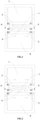
- the plurality of intermediate heat source sections include a first intermediate heat source section 1 and a second intermediate heat source section 2;
- the plurality of heating devices include a first heating device 3 and a second heating device 4 arranged in the first intermediate heat source section 1 and the second intermediate heat source section 2 respectively;
- both the first multi-position switching valve 5 and the second multi-position switching valve 6 are three-position switching valves.
- the three valve positions of the first multi-position switching valve 5 are A1, A2 and A3 respectively, and the three valve positions of the second multi-position switching valve 6 are B 1, B2 and B3 respectively.
- both the first intermediate heat source section 1 and the second intermediate heat source section 2 are connected to the second clothing drying device 8; that is, an inlet of the first intermediate heat source section 1 and an inlet of the second intermediate heat source section 2 both communicate with the hot air output section corresponding to the second clothing drying device 8, and an outlet of the first intermediate heat source section 1 and an outlet of the second intermediate heat source section 2 both communicate with the hot air input section corresponding to the second clothing drying device 8.
- the first multi-position switching valve 5 is in the valve position A2 and the second multi-position switching valve 6 is in the valve position B2 (see FIG.
- the first intermediate heat source section 1 is connected to the first clothing drying device 7 and the second intermediate heat source section 2 is connected to the second clothing drying device 8; that is, the inlet of the first intermediate heat source section 1 communicates with the hot air output section corresponding to the first clothing drying device 7, the inlet of the second intermediate heat source section 2 communicates with the hot air output section corresponding to the second clothing drying device 8, the outlet of the first intermediate heat source section 1 communicates with the hot air input section corresponding to the first clothing drying device 7, and the outlet of the second intermediate heat source section 2 communicates with the hot air input section corresponding to the second clothing drying device 8.
- the first multi-position switching valve 5 is in the valve position A3 and the second multi-position switching valve 6 is in the valve position B3 (see FIG.
- both the first intermediate heat source section 1 and the second intermediate heat source section 2 are connected to the first clothing drying device 7; that is, the inlet of the first intermediate heat source section 1 and the inlet of the second intermediate heat source section 2 both communicate with the hot air output section corresponding to the first clothing drying device 7, and the outlet of the first intermediate heat source section 1 and the outlet of the second intermediate heat source section 2 both communicate with the hot air input section corresponding to the first clothing drying device 7.
- both the first intermediate heat source section 1 and the second intermediate heat source section 2 are connected to the second clothing drying device 8
- the first heating device 3 and the second heating device 4 can simultaneously supply heat to the second clothing drying device 8, namely, dual-heat-source heat supply; of course, it is also possible to supply heat to the second clothing drying device 8 only through the first heating device 3 or the second heating device 4, namely, single-heat-source heat supply, so as to adjust the heat level of the second clothing drying device 8.
- both the first intermediate heat source section 1 and the second intermediate heat source section 2 are connected to the first clothing drying device 7, the first heating device 3 and the second heating device 4 can simultaneously supply heat to the first clothing drying device 7, namely, dual-heat-source heat supply; of course, it is also possible to supply heat to the first clothing drying device 7 only through the first heating device 3 or the second heating device 4, namely, single-heat-source heat supply, so as to adjust the heat level of the first clothing drying device 7.
- the first clothing drying device 7 and the second clothing drying device 8 can be supplied with heat respectively, and there is no mutual restriction between the time of turning on or off the first clothing drying device 7 and the time of turning on or off the second clothing drying device 8; that is, the second clothing drying device 8 can be turned on at any time during the operation of the first clothing drying device 7, and the first clothing drying device 7 can be turned on at any time during the operation of the second clothing drying device 8.
- the drying airflow provided by the first heating device 3 to the first clothing drying device 7 can have a different temperature from the drying airflow provided by the second heating device 4 to the second clothing drying device 8.
- the first heating device 3 may be a heat pump device, an electric heating pipe, an electric heating wire or a PTC heater; similarly, the second heating device 4 may be a heat pump device, an electric heating pipe, an electric heating wire or a PTC heater.
- the first heating device 3 is a heat pump device, and the heat pump device includes an evaporator, a condenser and a compressor that constitute a refrigerant circulation loop.
- the evaporator and the condenser are both arranged in the first intermediate heat source section 1, and the evaporator is located on an upstream side of the condenser in the flow direction of the air.
- the evaporator is configured to dehumidify the air
- the condenser is configured to heat the air.
- the plurality of intermediate heat source sections include a first intermediate heat source section and a second intermediate heat source section
- the plurality of heating devices include at least one first heating device and a plurality of second heating devices arranged in the first intermediate heat source section and the second intermediate heat source section respectively
- the first multi-position switching valve and the second multi-position switching valve are both three-position switching valves.
- the first heating device in the first intermediate heat source section may be one, or may be plural
- the second heating devices in the second intermediate heat source section is plural.
- the plurality of second heating device can be all turned off, or all turned on, or part of them are turned on and the other part of them are turned off, which can be specifically adjusted flexibly according to the heat level required by the user.
- the plurality of second heating devices may be all turned on, or part of them are turned on and the other part of them are turned off, so that the drying device connected to the second intermediate heat source section can adjust the heat level.
- the first heating device is at least one of a heat pump device, an electric heating pipe, an electric heating wire and a PTC heater; and/or the plurality of second heating devices are at least two of a heat pump device, an electric heating pipe, an electric heating wire and a PTC heater. That is, each second heating device may be a heat pump device, an electric heating pipe, an electric heating wire, or a PTC heater.
- Those skilled in the art can flexibly set the specific structures of the first heating device and the second heating device in practical applications. Such adjustments and changes to the specific structures of the first heating device and the second heating device do not constitute limitations to the present disclosure, and they should all be defined within the scope of protection of the present disclosure.
- the plurality of intermediate heat source sections include at least three intermediate heat source sections, the plurality of heating devices include at least one heating device arranged in each intermediate heat source section respectively, and the switching positions of the first multi-position switching valve and the second multi-position switching valve are in a one-to-one correspondence with each intermediate heat source section.
- the number of the intermediate heat source sections is at least three, and the heating device in each intermediate heat source section may be one, or may be plural.
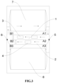
- the intermediate heat source sections are a first intermediate heat source section, a second intermediate heat source section and a third intermediate heat source section respectively;
- the first multi-position switching valve and the second multi-position switching valve each have four valve positions, so that the switching positions of the first multi-position switching valve and the second multi-position switching valve are in a one-to-one correspondence with each intermediate heat source section
- the one-to-one correspondence herein does not mean that the number of switching positions are in a one-to-one correspondence with the number of the intermediate heat source sections, but means that the number of switching positions are in a one-to-one correspondence with the number of channel boundaries formed by all the intermediate heat source sections; for example, the number of channel boundaries formed by three intermediate heat source sections is four, so the number of switching positions corresponding to the three intermediate heat source sections is four, whereas the number of channel boundaries formed by the two intermediate heat source sections in the first and second embodiments is three, so the number of switching positions corresponding to the two intermediate
- the four valve positions of the first multi-position switching valve are A1, A2, A3 and A4 respectively, and the four valve positions of the second multi-position switching valve are B 1, B2, B3 and B4.
- the first multi-position switching valve is in the valve position A1 and the second multi-position switching valve is in the valve position B 1
- the first intermediate heat source section, the second intermediate heat source section and the third intermediate heat source section are all connected to the second clothing drying device, that is, an inlet of the first intermediate heat source section, an inlet of the second intermediate heat source section and an inlet of the third intermediate heat source section all communicate with the hot air output section corresponding to the second clothing drying device, and an outlet of the first intermediate heat source section, an outlet of the second intermediate heat source section and an outlet of the third intermediate heat source section all communicate with the hot air input section corresponding to the second clothing drying device.
- the first intermediate heat source section is connected to the first clothing drying device, and the second intermediate heat source section and the third intermediate heat source section are connected to the second clothing drying device, that is, the inlet of the first intermediate heat source section communicates with the hot air output section corresponding to the first clothing drying device, and the inlet of the second intermediate heat source section and the inlet of the third intermediate heat source section both communicate with the hot air output section corresponding to the second clothing drying device; the outlet of the first intermediate heat source section communicates with the hot air input section corresponding to the first clothing drying device, and the outlet of the second intermediate heat source section and the outlet of the third intermediate heat source section both communicate with the hot air input section corresponding to the second clothing drying device.
- the first multi-position switching valve When the first multi-position switching valve is in the valve position A3 and the second multi-position switching valve is in the valve position B3, the first intermediate heat source section and the second intermediate heat source section are connected to the first clothing drying device, and the third intermediate heat source section is connected to the second clothing drying device, that is, the inlet of the first intermediate heat source section and the inlet of the second intermediate heat source section both communicate with the hot air output section corresponding to the first clothing drying device, and the inlet of the third intermediate heat source section communicates with the hot air output section corresponding to the second clothing drying device; the outlet of the first intermediate heat source section and the outlet of the second intermediate heat source section both communicate with the hot air input section corresponding to the first clothing drying device, and the outlet of the third intermediate heat source section communicates with the hot air input section corresponding to the second clothing drying device.
- the first intermediate heat source section, the second intermediate heat source section and the third intermediate heat source section are all connected to the first clothing drying device, that is, the inlet of the first intermediate heat source section, the inlet of the second intermediate heat source section and the inlet of the third intermediate heat source section all communicate with the hot air output section corresponding to the first clothing drying device, and the outlet of the first intermediate heat source section, the outlet of the second intermediate heat source section and the outlet of the third intermediate heat source section all communicate with the hot air input section corresponding to the first clothing drying device.
- the plurality of heating devices include each one heating device arranged in each of the intermediate heat source sections respectively.
- Each heating device is a heat pump device, an electric heating pipe, an electric heating wire or a PTC heater.
Landscapes
- Engineering & Computer Science (AREA)
- Textile Engineering (AREA)
- Detail Structures Of Washing Machines And Dryers (AREA)
- Drying Of Solid Materials (AREA)
Claims (10)
- Eine Kleidertrocknungsvorrichtung, bei der die Kleidertrocknungsvorrichtung einen Luftkanal, eine Luftwegschaltanlage, eine Vielzahl von Kleidertrocknungsvorrichtungen (7, 8) umfasst;der Luftkanal umfasst mehrere Heißluftzuführungsabschnitte, mehrere Heißluftausgangsabschnitte und mehrere Zwischenwärmequellenabschnitte (1, 2); jede der Heißluftzuführungsabschnitte und jeder der Heißluftaustrittsabschnitte sind in einer Einzelkorrespondenz mit jeder der Kleidungstrocknungseinrichtungen angeordnet (7, 8); jede der Zwischenwärmequellenabschnitte (1,2) ist mit mindestens einer Heizvorrichtung (3,4) ausgestattet;Die Luftpfadschaltanlage besteht aus einem ersten Mehrlagenschalteglied (5) und einem zweiten Mehrlagenschalteglied (6), die zwischen den Heißluftzuführungsabschnitten und den Zwischenwärmequellenabschnitten (1, 2) sowie zwischen den Heißluftaustrittsabschnitten und den Zwischenwärmequellenabschnitten angeordnet sind; das erste Mehrlagenschalteglied (5) und das zweite Mehrlagenschalteglied (6) haben die gleiche Anzahl von Schaltpositionen und sind so angeordnet, dass sie miteinander zusammenarbeiten, um mindestens eine der Kleidungstrocknungseinrichtungen (7, 8) selektiv mit dem entsprechenden Heißlufteingangsabschnitt, dem Heißluftausgangsabschnitt und dem Zwischenwärmequellenabschnitt zu kommunizieren, um eine Zirkulationsschleife zu bilden;dadurch gekennzeichnet, dass die Kleidertrocknungsvorrichtung eine Vielzahl von Heizvorrichtungen umfasst (3, 4), wobei jede der Heizvorrichtungen (3, 4) so angeordnet ist, dass sie unabhängig ein- oder ausgeschaltet werden können; und die Anzahl der Zwischenwärmequellenabschnitte (1,2) größer oder gleich der Anzahl der Kleidertrocknungseinrichtungen ist, und wenn mindestens zwei Zwischenwärmequellenabschnitte (1, 2) gleichzeitig mit einer Kleidertrocknungseinrichtung (7, 8) verbunden sind, wird eine Trocknungstemperatur dieser Kleidertrocknungseinrichtung (7, 8) durch Steuerung der Heizvorrichtung (3, 4) in jedem der angeschlossenen Zwischenwärmequellenabschnitte (1, 2) gesteuert.
- Die Kleidertrocknungsvorrichtung gemäß Anspruch 1, wobei die Vielzahl von Kleidertrocknungsvorrichtungen eine erste Kleidertrocknungsvorrichtung (7) und eine zweite Kleidertrocknungsvorrichtung (8) sowie das erste Mehrlagenschalterelement und das zweite Mehrlagenschalterelement ein erstes Mehrlagenschalterventil (5) bzw. ein zweites Mehrlagenschalterventil (6) umfassen.
- Die Kleidertrocknungsvorrichtung gemäß Anspruch 2, wobei die Mehrzahl von Zwischenwärmequellenabschnitten einen ersten Zwischenwärmequellenabschnitt (1) und einen zweiten Zwischenwärmequellenabschnitt (2) umfassen, umfassen die Mehrzahl von Heizvorrichtungen eine erste Heizvorrichtung (3) und eine zweite Heizvorrichtung (4), die im ersten Zwischenwärmequellenabschnitt (1) bzw. im zweiten Zwischenwärmequellenabschnitt (2) angeordnet sind, und das erste Mehrlagenschalterventil (5) und das zweite Mehrlagenschalterventil (6) sind beide Dreistellschaltventile.
- Die Kleidertrocknungsvorrichtung gemäß Anspruch 3, wobei eine der ersten Heizvorrichtung (3) und die zweite Heizvorrichtung (4) eine Wärmepumpenvorrichtung ist, und die andere der ersten Heizvorrichtung (3) und der zweiten Heizvorrichtung (4) ein elektrisches Heizrohr, ein elektrischer Heizdraht oder eine PTC-Heizung ist.
- Die Kleidertrocknungsvorrichtung gemäß Anspruch 2, wobei die Mehrzahl von Zwischenwärmequellenabschnitten einen ersten Zwischenwärmequellenabschnitt (1) und einen zweiten Zwischenwärmequellenabschnitt (2) umfassen, umfassen die Mehrzahl von Heizvorrichtungen mindestens eine erste Heizvorrichtung (3) und eine Vielzahl von zweiten Heizvorrichtungen (4), die im ersten Zwischenwärmequellenabschnitt (1) bzw. im zweiten Zwischenwärmequellenabschnitt (2) angeordnet sind, und das erste Mehrlagenschalterventil (5) und das zweite Mehrlagenschalterventil (6) sind beide Dreistellschaltventile.
- Die Kleidertrocknungsvorrichtung gemäß Anspruch 5, wobei die erste Heizvorrichtung (3) mindestens eine von einer Wärmepumpenvorrichtung, einem elektrischen Heizrohr, einem elektrischen Heizdraht und einer PTC-Heizung ist; und/oder
Die Mehrzahl der zweiten Heizvorrichtungen (4) sind mindestens zwei von einer Wärmepumpeneinrichtung, einem elektrischen Heizrohr, einem elektrischen Heizdraht und einer PTC-Heizung. - Die Kleidertrocknungsvorrichtung gemäß Anspruch 2, wobei die Mehrzahl von Zwischenwärmequellenabschnitten mindestens drei Zwischenwärmequellenabschnitte umfassen, die Mehrzahl von Heizvorrichtungen mindestens eine in jedem der Zwischenwärmequellenabschnitte angeordnete Heizvorrichtung umfassen, und die Schaltpositionen des ersten Mehrlagenschalterventils (5) und des zweiten Mehrlagenschalterventils (6) in einer Eins-zu-Eins-Entsprechung mit jedem der Zwischenwärmequellenabschnitte sind.
- Die Kleidertrocknungsvorrichtung gemäß Anspruch 7, wobei die Mehrzahl der Heizvorrichtungen jeweils eine Heizvorrichtung umfasst, die in jedem der Zwischenwärmequellenabschnitte angeordnet ist.
- Die Kleidertrocknungsvorrichtung gemäß Anspruch 8, wobei jede der Heizvorrichtungen eine Wärmepumpenvorrichtung, ein elektrisches Heizrohr, ein elektrischer Heizdraht oder eine PTC-Heizung ist.
- Die Kleidungstrocknungsvorrichtung gemäß einem der Ansprüche 2 bis 9, wobei die Kleidungstrocknungsvorrichtung ein Zweitrommeltrockner ist, und die erste Kleidungstrocknungsvorrichtung (7) und die zweite Kleidungstrocknungsvorrichtung (8) sind ein oberer Kleidungstrockner und ein unterer Kleidungstrockner, die jeweils auf und ab gestapelt sind; oderDie Kleidungstrocknungsvorrichtung ist eine integrierte Zweitrommelwaschtrocknungsmaschine, und die erste Kleidungstrocknungsvorrichtung (7) und die zweite Kleidungstrocknungsvorrichtung (8) sind eine integrierte obere und eine untere integrierte Waschmaschine, die nach oben und unten gestapelt sind; oderDie Kleidungstrocknungsvorrichtung ist eine Zweitrommelmischmaschine, und die erste Kleidungstrocknungsvorrichtung (7) und die zweite Kleidungstrocknungsvorrichtung (8) sind eine obere Waschtrockner-integrierte Maschine und ein unterer Kleidungstrockner, die jeweils nach oben und unten gestapelt sind; oderDie Kleidungstrocknungsvorrichtung ist eine Zweitrommelmischmaschine, und die erste Kleidungstrocknungsvorrichtung (7) und die zweite Kleidungstrocknungsvorrichtung (8) sind ein oberer Kleidungstrockner und eine untere Waschtrockner integrierte Maschine, die jeweils auf und ab gestapelt sind.
Applications Claiming Priority (3)
| Application Number | Priority Date | Filing Date | Title |
|---|---|---|---|
| CN201911395871.7A CN113123093A (zh) | 2019-12-30 | 2019-12-30 | 干衣设备的供热方法及干衣设备 |
| CN201911399455.4A CN113123094A (zh) | 2019-12-30 | 2019-12-30 | 干衣设备 |
| PCT/CN2020/129033 WO2021135686A1 (zh) | 2019-12-30 | 2020-11-16 | 干衣设备及其供热方法 |
Publications (4)
| Publication Number | Publication Date |
|---|---|
| EP4086382A1 EP4086382A1 (de) | 2022-11-09 |
| EP4086382A4 EP4086382A4 (de) | 2023-06-21 |
| EP4086382B1 true EP4086382B1 (de) | 2024-10-16 |
| EP4086382C0 EP4086382C0 (de) | 2024-10-16 |
Family
ID=76686408
Family Applications (1)
| Application Number | Title | Priority Date | Filing Date |
|---|---|---|---|
| EP20909401.0A Active EP4086382B1 (de) | 2019-12-30 | 2020-11-16 | Wäschetrockner |
Country Status (3)
| Country | Link |
|---|---|
| US (1) | US12428775B2 (de) |
| EP (1) | EP4086382B1 (de) |
| WO (1) | WO2021135686A1 (de) |
Families Citing this family (2)
| Publication number | Priority date | Publication date | Assignee | Title |
|---|---|---|---|---|
| US12428775B2 (en) * | 2019-12-30 | 2025-09-30 | Qingdao Haier Washing Machine Co., Ltd. | Clothes drying device and heat supply method therefor |
| US11866866B2 (en) * | 2020-05-27 | 2024-01-09 | Monotony.ai, Inc. | Autonomous laundry washing and drying systems and methods |
Family Cites Families (26)
| Publication number | Priority date | Publication date | Assignee | Title |
|---|---|---|---|---|
| US2961776A (en) * | 1958-09-26 | 1960-11-29 | Gen Electric | Clothes dryer with reversible blower |
| US3218730A (en) * | 1962-06-14 | 1965-11-23 | Gen Motors Corp | Termination control for a condensing clothes dryer |
| US3555701A (en) | 1969-05-15 | 1971-01-19 | Philco Ford Corp | Laundry apparatus |
| IT9045755A1 (it) * | 1990-09-25 | 1992-03-25 | Zanussi Elettrodomestici | Asciugabiancheria con accessori integrati |
| US5369892A (en) * | 1993-06-04 | 1994-12-06 | Dhaemers; Gregory L. | Armoire |
| KR100652459B1 (ko) | 2005-11-25 | 2006-12-01 | 엘지전자 주식회사 | 일체형 세탁 건조기 |
| KR100808199B1 (ko) * | 2006-07-28 | 2008-02-29 | 엘지전자 주식회사 | 복합 의류 처리 장치 |
| KR100774206B1 (ko) * | 2006-07-28 | 2007-11-08 | 엘지전자 주식회사 | 복합 의류 처리 장치 및 이의 제어 방법 |
| JP4858321B2 (ja) * | 2007-06-13 | 2012-01-18 | パナソニック株式会社 | 衣類乾燥機 |
| DE102008033388B4 (de) * | 2008-07-16 | 2020-07-16 | BSH Hausgeräte GmbH | Trockner mit Wärmepumpenkreis |
| EP2576888B1 (de) * | 2010-06-07 | 2014-03-19 | Arçelik Anonim Sirketi | Wäschetrockner mit thermoelektrischer wärmepumpe |
| WO2012134148A2 (en) * | 2011-03-29 | 2012-10-04 | Lg Electronics Inc. | Controlling method for clothes dryer |
| CN102758342B (zh) * | 2012-02-24 | 2015-10-14 | 上海鸿尔机械有限公司 | 双转笼式烘干机 |
| CN108950976A (zh) * | 2017-05-27 | 2018-12-07 | 青岛海尔滚筒洗衣机有限公司 | 衣物处理设备 |
| CN109402985B (zh) * | 2017-08-18 | 2022-05-27 | 青岛海尔滚筒洗衣机有限公司 | 衣物处理装置及衣物处理方法 |
| US10494756B2 (en) * | 2017-11-16 | 2019-12-03 | Haier Us Appliance Solutions, Inc. | Dryer appliances including an air circulation duct |
| CN108085941A (zh) * | 2018-01-02 | 2018-05-29 | 珠海格力电器股份有限公司 | 烘干系统、洗涤烘干一体机及其控制方法 |
| CN208562910U (zh) * | 2018-06-26 | 2019-03-01 | 青岛海尔滚筒洗衣机有限公司 | 衣物处理设备 |
| US10995448B2 (en) * | 2019-09-27 | 2021-05-04 | Whirlpool Corporation | Laundry treating appliance with a condenser |
| US12428775B2 (en) * | 2019-12-30 | 2025-09-30 | Qingdao Haier Washing Machine Co., Ltd. | Clothes drying device and heat supply method therefor |
| KR102805587B1 (ko) * | 2020-03-09 | 2025-05-14 | 엘지전자 주식회사 | 의류처리장치 및 그 제어방법 |
| US11866866B2 (en) * | 2020-05-27 | 2024-01-09 | Monotony.ai, Inc. | Autonomous laundry washing and drying systems and methods |
| EP4556830A3 (de) * | 2020-12-23 | 2025-08-06 | LG Electronics Inc. | Trocknungsvorrichtung |
| CN113106713A (zh) * | 2021-04-01 | 2021-07-13 | 江苏友奥电器有限公司 | 一种干衣机 |
| CN115404633A (zh) * | 2021-05-28 | 2022-11-29 | Lg电子株式会社 | 衣物处理装置 |
| JP2023165561A (ja) * | 2022-05-06 | 2023-11-16 | 青島海爾洗衣机有限公司 | 洗濯乾燥機 |
-
2020
- 2020-11-16 US US17/789,413 patent/US12428775B2/en active Active
- 2020-11-16 WO PCT/CN2020/129033 patent/WO2021135686A1/zh not_active Ceased
- 2020-11-16 EP EP20909401.0A patent/EP4086382B1/de active Active
Also Published As
| Publication number | Publication date |
|---|---|
| EP4086382A4 (de) | 2023-06-21 |
| EP4086382A1 (de) | 2022-11-09 |
| US12428775B2 (en) | 2025-09-30 |
| US20230043093A1 (en) | 2023-02-09 |
| WO2021135686A1 (zh) | 2021-07-08 |
| EP4086382C0 (de) | 2024-10-16 |
Similar Documents
| Publication | Publication Date | Title |
|---|---|---|
| US20210148030A1 (en) | Laundry treatment equipment | |
| JP6800333B2 (ja) | 空気調和機及び空気調和システム | |
| JP7236205B2 (ja) | 衣類処理装置 | |
| EP2922993B1 (de) | Verfahren zur steuerung eines wäschetrockners mit variabler trommeldrehzahl und variabler lüfterdrehzahl | |
| EP4086382B1 (de) | Wäschetrockner | |
| KR102100473B1 (ko) | 폐열 회수수단을 갖는 의류처리장치 | |
| CN117286693B (zh) | 一种衣物处理设备及衣物处理设备的烘干控制方法 | |
| JP2008188147A (ja) | 洗濯乾燥システム | |
| CN102505436A (zh) | 一种热泵洗干一体机及烘干方式 | |
| KR101564096B1 (ko) | 바이패스 덕트를 구비한 열회수형 환기 시스템 | |
| CN106322685A (zh) | 空调恒温除湿的控制方法及空调 | |
| CN110513769B (zh) | 一种空调器、控制装置和控制方法 | |
| CN107702208A (zh) | 室内机 | |
| CN210511923U (zh) | 空调柜机 | |
| CN222100435U (zh) | 一种干衣装置 | |
| CN107687676B (zh) | 室内机 | |
| CN106979556A (zh) | 柜机空调 | |
| CN112728646A (zh) | 一种立式空调及其控制方法 | |
| CN113123094A (zh) | 干衣设备 | |
| CN117966448A (zh) | 一种干衣装置及烘干控制方法 | |
| CN212319842U (zh) | 一种暖气供给调节装置、烘干机和基于空调器的烘干系统 | |
| CN110904653B (zh) | 干衣设备 | |
| CN107560088A (zh) | 空调器的控制方法 | |
| JP2016090124A (ja) | 浴室乾燥装置 | |
| JP2017058121A (ja) | 浴室空気調和機 |
Legal Events
| Date | Code | Title | Description |
|---|---|---|---|
| STAA | Information on the status of an ep patent application or granted ep patent |
Free format text: STATUS: THE INTERNATIONAL PUBLICATION HAS BEEN MADE |
|
| PUAI | Public reference made under article 153(3) epc to a published international application that has entered the european phase |
Free format text: ORIGINAL CODE: 0009012 |
|
| STAA | Information on the status of an ep patent application or granted ep patent |
Free format text: STATUS: REQUEST FOR EXAMINATION WAS MADE |
|
| 17P | Request for examination filed |
Effective date: 20220701 |
|
| AK | Designated contracting states |
Kind code of ref document: A1 Designated state(s): AL AT BE BG CH CY CZ DE DK EE ES FI FR GB GR HR HU IE IS IT LI LT LU LV MC MK MT NL NO PL PT RO RS SE SI SK SM TR |
|
| DAV | Request for validation of the european patent (deleted) | ||
| DAX | Request for extension of the european patent (deleted) | ||
| REG | Reference to a national code |
Free format text: PREVIOUS MAIN CLASS: D06F0029000000 Ipc: D06F0058020000 Ref country code: DE Ref legal event code: R079 Ref document number: 602020039731 Country of ref document: DE Free format text: PREVIOUS MAIN CLASS: D06F0029000000 Ipc: D06F0058020000 |
|
| STAA | Information on the status of an ep patent application or granted ep patent |
Free format text: STATUS: EXAMINATION IS IN PROGRESS |
|
| A4 | Supplementary search report drawn up and despatched |
Effective date: 20230524 |
|
| RIC1 | Information provided on ipc code assigned before grant |
Ipc: D06F 105/32 20200101ALN20230517BHEP Ipc: D06F 105/28 20200101ALN20230517BHEP Ipc: D06F 105/26 20200101ALN20230517BHEP Ipc: D06F 103/06 20200101ALN20230517BHEP Ipc: D06F 58/26 20060101ALN20230517BHEP Ipc: D06F 58/38 20200101ALI20230517BHEP Ipc: D06F 58/20 20060101ALI20230517BHEP Ipc: D06F 58/02 20060101AFI20230517BHEP |
|
| 17Q | First examination report despatched |
Effective date: 20230605 |
|
| GRAP | Despatch of communication of intention to grant a patent |
Free format text: ORIGINAL CODE: EPIDOSNIGR1 |
|
| STAA | Information on the status of an ep patent application or granted ep patent |
Free format text: STATUS: GRANT OF PATENT IS INTENDED |
|
| RIC1 | Information provided on ipc code assigned before grant |
Ipc: D06F 105/32 20200101ALN20240418BHEP Ipc: D06F 105/28 20200101ALN20240418BHEP Ipc: D06F 105/26 20200101ALN20240418BHEP Ipc: D06F 103/06 20200101ALN20240418BHEP Ipc: D06F 58/26 20060101ALN20240418BHEP Ipc: D06F 58/38 20200101ALI20240418BHEP Ipc: D06F 58/20 20060101ALI20240418BHEP Ipc: D06F 58/02 20060101AFI20240418BHEP |
|
| RIC1 | Information provided on ipc code assigned before grant |
Ipc: D06F 105/32 20200101ALN20240423BHEP Ipc: D06F 105/28 20200101ALN20240423BHEP Ipc: D06F 105/26 20200101ALN20240423BHEP Ipc: D06F 103/06 20200101ALN20240423BHEP Ipc: D06F 58/26 20060101ALN20240423BHEP Ipc: D06F 58/38 20200101ALI20240423BHEP Ipc: D06F 58/20 20060101ALI20240423BHEP Ipc: D06F 58/02 20060101AFI20240423BHEP |
|
| INTG | Intention to grant announced |
Effective date: 20240510 |
|
| GRAS | Grant fee paid |
Free format text: ORIGINAL CODE: EPIDOSNIGR3 |
|
| GRAA | (expected) grant |
Free format text: ORIGINAL CODE: 0009210 |
|
| STAA | Information on the status of an ep patent application or granted ep patent |
Free format text: STATUS: THE PATENT HAS BEEN GRANTED |
|
| AK | Designated contracting states |
Kind code of ref document: B1 Designated state(s): AL AT BE BG CH CY CZ DE DK EE ES FI FR GB GR HR HU IE IS IT LI LT LU LV MC MK MT NL NO PL PT RO RS SE SI SK SM TR |
|
| REG | Reference to a national code |
Ref country code: GB Ref legal event code: FG4D |
|
| REG | Reference to a national code |
Ref country code: CH Ref legal event code: EP |
|
| REG | Reference to a national code |
Ref country code: IE Ref legal event code: FG4D |
|
| REG | Reference to a national code |
Ref country code: DE Ref legal event code: R096 Ref document number: 602020039731 Country of ref document: DE |
|
| U01 | Request for unitary effect filed |
Effective date: 20241112 |
|
| U07 | Unitary effect registered |
Designated state(s): AT BE BG DE DK EE FI FR IT LT LU LV MT NL PT RO SE SI Effective date: 20241119 |
|
| U20 | Renewal fee for the european patent with unitary effect paid |
Year of fee payment: 5 Effective date: 20241127 |
|
| PG25 | Lapsed in a contracting state [announced via postgrant information from national office to epo] |
Ref country code: IS Free format text: LAPSE BECAUSE OF FAILURE TO SUBMIT A TRANSLATION OF THE DESCRIPTION OR TO PAY THE FEE WITHIN THE PRESCRIBED TIME-LIMIT Effective date: 20250216 Ref country code: HR Free format text: LAPSE BECAUSE OF FAILURE TO SUBMIT A TRANSLATION OF THE DESCRIPTION OR TO PAY THE FEE WITHIN THE PRESCRIBED TIME-LIMIT Effective date: 20241016 |
|
| PG25 | Lapsed in a contracting state [announced via postgrant information from national office to epo] |
Ref country code: ES Free format text: LAPSE BECAUSE OF FAILURE TO SUBMIT A TRANSLATION OF THE DESCRIPTION OR TO PAY THE FEE WITHIN THE PRESCRIBED TIME-LIMIT Effective date: 20241016 |
|
| PG25 | Lapsed in a contracting state [announced via postgrant information from national office to epo] |
Ref country code: NO Free format text: LAPSE BECAUSE OF FAILURE TO SUBMIT A TRANSLATION OF THE DESCRIPTION OR TO PAY THE FEE WITHIN THE PRESCRIBED TIME-LIMIT Effective date: 20250116 |
|
| PG25 | Lapsed in a contracting state [announced via postgrant information from national office to epo] |
Ref country code: GR Free format text: LAPSE BECAUSE OF FAILURE TO SUBMIT A TRANSLATION OF THE DESCRIPTION OR TO PAY THE FEE WITHIN THE PRESCRIBED TIME-LIMIT Effective date: 20250117 |
|
| PG25 | Lapsed in a contracting state [announced via postgrant information from national office to epo] |
Ref country code: PL Free format text: LAPSE BECAUSE OF FAILURE TO SUBMIT A TRANSLATION OF THE DESCRIPTION OR TO PAY THE FEE WITHIN THE PRESCRIBED TIME-LIMIT Effective date: 20241016 |
|
| PG25 | Lapsed in a contracting state [announced via postgrant information from national office to epo] |
Ref country code: RS Free format text: LAPSE BECAUSE OF FAILURE TO SUBMIT A TRANSLATION OF THE DESCRIPTION OR TO PAY THE FEE WITHIN THE PRESCRIBED TIME-LIMIT Effective date: 20250116 |
|
| REG | Reference to a national code |
Ref country code: CH Ref legal event code: PL |
|
| PG25 | Lapsed in a contracting state [announced via postgrant information from national office to epo] |
Ref country code: SM Free format text: LAPSE BECAUSE OF FAILURE TO SUBMIT A TRANSLATION OF THE DESCRIPTION OR TO PAY THE FEE WITHIN THE PRESCRIBED TIME-LIMIT Effective date: 20241016 |
|
| PG25 | Lapsed in a contracting state [announced via postgrant information from national office to epo] |
Ref country code: MC Free format text: LAPSE BECAUSE OF FAILURE TO SUBMIT A TRANSLATION OF THE DESCRIPTION OR TO PAY THE FEE WITHIN THE PRESCRIBED TIME-LIMIT Effective date: 20241016 |
|
| REG | Reference to a national code |
Ref country code: CH Ref legal event code: PL |
|
| PG25 | Lapsed in a contracting state [announced via postgrant information from national office to epo] |
Ref country code: CH Free format text: LAPSE BECAUSE OF NON-PAYMENT OF DUE FEES Effective date: 20241130 |
|
| PG25 | Lapsed in a contracting state [announced via postgrant information from national office to epo] |
Ref country code: SK Free format text: LAPSE BECAUSE OF FAILURE TO SUBMIT A TRANSLATION OF THE DESCRIPTION OR TO PAY THE FEE WITHIN THE PRESCRIBED TIME-LIMIT Effective date: 20241016 |
|
| PG25 | Lapsed in a contracting state [announced via postgrant information from national office to epo] |
Ref country code: CZ Free format text: LAPSE BECAUSE OF FAILURE TO SUBMIT A TRANSLATION OF THE DESCRIPTION OR TO PAY THE FEE WITHIN THE PRESCRIBED TIME-LIMIT Effective date: 20241016 |
|
| PLBE | No opposition filed within time limit |
Free format text: ORIGINAL CODE: 0009261 |
|
| STAA | Information on the status of an ep patent application or granted ep patent |
Free format text: STATUS: NO OPPOSITION FILED WITHIN TIME LIMIT |
|
| 26N | No opposition filed |
Effective date: 20250717 |
|
| GBPC | Gb: european patent ceased through non-payment of renewal fee |
Effective date: 20250116 |
|
| PG25 | Lapsed in a contracting state [announced via postgrant information from national office to epo] |
Ref country code: GB Free format text: LAPSE BECAUSE OF NON-PAYMENT OF DUE FEES Effective date: 20250116 |
|
| PG25 | Lapsed in a contracting state [announced via postgrant information from national office to epo] |
Ref country code: IE Free format text: LAPSE BECAUSE OF NON-PAYMENT OF DUE FEES Effective date: 20241116 |
|
| U20 | Renewal fee for the european patent with unitary effect paid |
Year of fee payment: 6 Effective date: 20251028 |