EP4086206B1 - Verfahren und system zum beladen einer wärmebehandlungseinheit - Google Patents
Verfahren und system zum beladen einer wärmebehandlungseinheit Download PDFInfo
- Publication number
- EP4086206B1 EP4086206B1 EP21172144.4A EP21172144A EP4086206B1 EP 4086206 B1 EP4086206 B1 EP 4086206B1 EP 21172144 A EP21172144 A EP 21172144A EP 4086206 B1 EP4086206 B1 EP 4086206B1
- Authority
- EP
- European Patent Office
- Prior art keywords
- plate
- loading
- shaped objects
- selection
- storage unit
- Prior art date
- Legal status (The legal status is an assumption and is not a legal conclusion. Google has not performed a legal analysis and makes no representation as to the accuracy of the status listed.)
- Active
Links
Images


Classifications
-
- C—CHEMISTRY; METALLURGY
- C03—GLASS; MINERAL OR SLAG WOOL
- C03B—MANUFACTURE, SHAPING, OR SUPPLEMENTARY PROCESSES
- C03B29/00—Reheating glass products for softening or fusing their surfaces; Fire-polishing; Fusing of margins
- C03B29/04—Reheating glass products for softening or fusing their surfaces; Fire-polishing; Fusing of margins in a continuous way
- C03B29/06—Reheating glass products for softening or fusing their surfaces; Fire-polishing; Fusing of margins in a continuous way with horizontal displacement of the products
- C03B29/08—Glass sheets
-
- B—PERFORMING OPERATIONS; TRANSPORTING
- B65—CONVEYING; PACKING; STORING; HANDLING THIN OR FILAMENTARY MATERIAL
- B65G—TRANSPORT OR STORAGE DEVICES, e.g. CONVEYORS FOR LOADING OR TIPPING, SHOP CONVEYOR SYSTEMS OR PNEUMATIC TUBE CONVEYORS
- B65G49/00—Conveying systems characterised by their application for specified purposes not otherwise provided for
- B65G49/05—Conveying systems characterised by their application for specified purposes not otherwise provided for for fragile or damageable materials or articles
- B65G49/06—Conveying systems characterised by their application for specified purposes not otherwise provided for for fragile or damageable materials or articles for fragile sheets, e.g. glass
- B65G49/063—Transporting devices for sheet glass
- B65G49/064—Transporting devices for sheet glass in a horizontal position
-
- B—PERFORMING OPERATIONS; TRANSPORTING
- B65—CONVEYING; PACKING; STORING; HANDLING THIN OR FILAMENTARY MATERIAL
- B65G—TRANSPORT OR STORAGE DEVICES, e.g. CONVEYORS FOR LOADING OR TIPPING, SHOP CONVEYOR SYSTEMS OR PNEUMATIC TUBE CONVEYORS
- B65G49/00—Conveying systems characterised by their application for specified purposes not otherwise provided for
- B65G49/05—Conveying systems characterised by their application for specified purposes not otherwise provided for for fragile or damageable materials or articles
- B65G49/06—Conveying systems characterised by their application for specified purposes not otherwise provided for for fragile or damageable materials or articles for fragile sheets, e.g. glass
- B65G49/067—Sheet handling, means, e.g. manipulators, devices for turning or tilting sheet glass
-
- B—PERFORMING OPERATIONS; TRANSPORTING
- B65—CONVEYING; PACKING; STORING; HANDLING THIN OR FILAMENTARY MATERIAL
- B65G—TRANSPORT OR STORAGE DEVICES, e.g. CONVEYORS FOR LOADING OR TIPPING, SHOP CONVEYOR SYSTEMS OR PNEUMATIC TUBE CONVEYORS
- B65G49/00—Conveying systems characterised by their application for specified purposes not otherwise provided for
- B65G49/05—Conveying systems characterised by their application for specified purposes not otherwise provided for for fragile or damageable materials or articles
- B65G49/06—Conveying systems characterised by their application for specified purposes not otherwise provided for for fragile or damageable materials or articles for fragile sheets, e.g. glass
- B65G49/068—Stacking or destacking devices; Means for preventing damage to stacked sheets, e.g. spaces
-
- C—CHEMISTRY; METALLURGY
- C03—GLASS; MINERAL OR SLAG WOOL
- C03B—MANUFACTURE, SHAPING, OR SUPPLEMENTARY PROCESSES
- C03B35/00—Transporting of glass products during their manufacture, e.g. hot glass lenses, prisms
- C03B35/14—Transporting hot glass sheets or ribbons, e.g. by heat-resistant conveyor belts or bands
Definitions
- the present invention relates to a method for loading a heat treatment unit with plate-shaped objects, in particular glass plates.
- the present invention relates to a system for loading a heat treatment unit with plate-shaped objects, in particular glass plates.
- Tempered glass often also referred to as safety glass, is characterized by good strength, heat resistance and a breakage behavior that prevents injuries and is used, among other things, for entrance doors, shower cubicles and doors of wood stoves and fireplaces.
- the baking trays each have several equally sized recesses that are arranged in a grid on the baking tray, with each recess being able to accommodate a glass pane transferred by the manipulator.
- the baking trays, each of which is covered with several glass panes, can be stacked on top of one another, making it easier to the handling of the glass panes for subsequent, unspecified treatment steps.
- the disadvantage is that the sorting and conveying device is only suitable for identical glass panes with the same dimensions.
- the production of tempered glass panels usually requires several processing steps. First, the glass is cut into panels of the desired size in a cutting line. Then the cut edges of the glass panels are The glass sheets are then edged, ground and/or polished on a grinding line. If necessary, the glass sheets then pass through a screen printing line before being fed to a glass hardening line to be heated in a corresponding heat treatment unit and then rapidly cooled, whereby the outer surface of the glass sheets contracts more quickly than the middle. This gives the glass sheets their good strength.
- the heat treatment unit is kept more or less constantly at a heat treatment temperature of over 600°C - i.e. the strength of the glass plates is adjusted by the length of time the glass plates spend in the heat treatment unit. It should be noted that - if the different glass plates are to have the same strength - the length of time the glass plates with a greater thickness or with a (thicker) coating stay in the heat treatment unit must be correspondingly longer than the length of time the glass plates with a smaller thickness or with a thin or no coating at all. This means that the glass plates must be sorted into a selection based on certain parameters, in particular the thickness and/or the coating, so that glass plates with the same or similar parameters pass through the heat treatment unit at the same time to ensure that uniform strength results are achieved.
- the area or space available within the heat treatment unit is used as best as possible - i.e. that the area or space is covered or filled as completely as possible with glass plates.
- Only one type of glass may be loaded into a single loaded hardening bed, e.g. only 4 mm float glass or only 4 mm low-e coated glass or only 6 mm glass thickness with applied enamel paint, etc.
- only glass panes with an approximately similar length/aspect ratio may be loaded or the glass plates may only be loaded in a certain orientation on the hardening bed, e.g. only with a narrow glass edge running forward. Due to the variety of different loading specifications, efficient nesting of the glass plates on a certain surface is a very complex task.
- steps a), b) and c) can first be carried out one after the other for an object in the object stream.
- step a) can be carried out for another object in the object stream; in other words: one or more of steps a) to c) can be carried out for different objects in the object stream at the same time, or one of steps a) to c) does not have to be carried out for all or several objects in the object stream before another of steps a) to c) can be carried out.
- step d) only those objects can be taken into account for which step c) has already been completed.
- the method according to the invention can be automated.
- the plate-shaped objects are removed from a storage rack, for example from a shelf arrangement or from a delivery rack, in particular an L or A rack, or from a compartment trolley and are placed on an infeed section of a production line, preferably in a vertical arrangement - i.e. standing; alternatively, the plate-shaped objects can also be placed on the infeed section, preferably in a horizontal arrangement - i.e. lying down. Accordingly, the removed plate-shaped objects form an object stream for the method according to the invention.
- the respective plate-shaped object is stored at a storage location in the storage unit. It is also conceivable that objects in the object stream are stored in the storage unit without at least one parameter of these objects having been recorded immediately beforehand.
- the storage unit comprises several horizontally and/or vertically arranged compartments designed to accommodate plate-shaped objects, whereby each compartment can have one or more storage locations.
- Information on the respective storage location and/or on at least one recorded parameter of the respective plate-shaped objects is then stored, for example on a data carrier, such as a hard disk or a USB stick, or in a data cloud (cloud storage). Alternatively, this information is recorded in such a way that it can be used to calculate the loading arrangement.
- a data carrier such as a hard disk or a USB stick
- a data cloud cloud storage
- the plate-shaped objects differ only in one of their dimensions, for example their height, or in one of their properties, for example their material type.
- the storage unit can be divided into several Areas can be divided into one or more storage locations, in which areas plate-shaped objects with identical dimensions/properties are stored. In this case, only the respective storage location would have to be saved, since the respective parameters already result from the respective area or storage location.
- the loading system can be designed as a loading table, infeed table, bed or hardening bed.
- the calculation of the loading arrangement is therefore an optimization problem (optimization task) that can be solved using known numerical methods.
- secondary or boundary conditions can also be taken into account, which secondary or boundary conditions the solution to the optimization problem, i.e. the loading arrangement, should also fulfill.
- the following methods can be used: hill climbing algorithm, BFGS method, branch-and-bound, cutting plane method, branch-and-cut, pivot method, simplex method, downhill simplex method, interior point method, logarithmic barrier method, simulated annealing.
- the selection of plate-shaped objects is removed from the respective storage location and these plate-shaped objects are transported to the loading system.
- the selection of plate-shaped objects is finally transferred to the loading system in the loading order corresponding to the calculated loading arrangement, in which loading order the selection is to be positioned on or in the loading system, and positioned on or in the loading system.
- the loading arrangement of the selection i.e. the hardening bed with which the heat treatment unit is to be loaded, is created.
- the removal and/or transport of the selection of plate-shaped objects already takes place in the loading order.
- the heat treatment unit can be formed by a hardening furnace and can also include a quenching or cooling unit with a cooling unit.
- the method according to the invention enables the throughput, which is the number of plate-shaped objects that pass through the heat treatment unit in a certain unit of time, to be significantly increased by the heat treatment unit.
- the plate-shaped objects of the selection can be transferred to the loading system in the "correct" order, i.e. in the loading order, and in a particularly time-saving manner, since the loading arrangement for the entire selection of plate-shaped objects is calculated in advance of loading and the plate-shaped objects can be removed from the storage unit or accessed in essentially any order due to their storage at different storage locations - i.e.
- the plate-shaped objects must be arranged on or in the loading system essentially according to the order specified by the object flow, or - in order to be able to process the objects in a different order - laborious and complex sorting processes must be carried out manually.
- glass plates must be removed from a compartment trolley, in which they are arranged one behind the other or parallel to one another according to their size, in the exact order (and manually placed on the hardening bed) that results from the arrangement of the glass plates in the compartment trolley; if the glass plates are removed in a different order, there is a high risk of scratches or breakage.
- the possible loading arrangements of the glass plates in the compartment trolley are therefore very limited by the predetermined order in which the glass plates must be removed and positioned on the hardening bed.
- the method according to the invention enables the plate-shaped objects of the object stream to be transferred to the loading system in a very flexible manner or in any order.
- plate-shaped objects of the selection are stored in directly adjacent and/or quickly accessible storage locations of the other storage unit and/or the storage unit, so that the plate-shaped objects of the selection can be removed particularly quickly.
- the plate-shaped objects are sorted, further processed and/or stored after passing through the heat treatment unit based on the information provided, in particular based on the batch number provided, and/or that the plate-shaped objects are again provided with labels, production papers or the like on the basis of the information provided, i.e. that at least parts of the information provided are assigned to the plate-shaped objects of the selection, for example in the form of an adhesive label comprising a bar code or barcode and stuck to the surface of the respective plate-shaped object.
- the at least one processing unit can preferably be a shuttle (storage shuttle, also channel vehicle or satellite vehicle) that can be moved on rails. It is conceivable that the "processing" of the at least one processing unit is to be understood as merely a change in location of the plate-shaped objects. Of course, it is not excluded that the processing unit can also carry out further processing steps, such as cleaning the surfaces of the plate-shaped objects.
- control unit is designed to calculate a loading arrangement of the selection of the plate-shaped objects on or in the loading system using the respective recorded parameters and/or the respective storage locations and taking into account predeterminable main and, if applicable, secondary or boundary conditions.
- control unit enables the calculation of the optimal loading arrangement on the basis of information on the recorded parameters and the storage locations of the plate-shaped objects.
- secondary or boundary conditions can also be taken into account.
- the plate-shaped objects are particularly preferably checked for individual or all of the recorded parameters.
- the system comprises a control unit, which is preferably arranged between the recording unit and the storage unit. Using this control unit, the plate-shaped object is now checked for one or all of the recorded parameters, i.e. it is checked whether the plate-shaped object actually has the parameters stored on the corresponding label or production paper or the like and recorded by the recording unit (e.g. size, thickness, type of material, coating). If discrepancies are noticed during this check, incorrect parameters can be replaced by the parameters recorded by the control unit.
- the control unit can also be used to check the orientation or positioning of the plate-shaped object, in particular with regard to any coating, and to correct this manually if necessary.
- the system has a further processing unit, for example a further shuttle, for loading and/or unloading the further storage unit with plate-shaped objects. This makes it possible to increase the speed of loading and/or unloading the further storage unit.
- a further processing unit for example a further shuttle
- the further processing unit is arranged directly behind the at least one storage unit, as seen in the object conveying direction.
- the second variant (b, c) of this embodiment of the system according to the invention allows the processing time to be further optimized, since two processing units, such as two shuttles, are available. This means that the two storage units can be loaded and unloaded as quickly as possible with this arrangement.
- processing unit and/or the further processing unit is additionally arranged and designed for loading a station of the production line downstream of the further storage unit, such as a conveyor section of the production line, for example a tilting table.
- the processing unit can be arranged directly in front of the storage unit as seen in the object conveying direction, while the further processing unit can be arranged between the storage unit and the further storage unit.
- the delivery table is therefore designed to be able to correctly position the plate-shaped objects of the selection according to the calculated loading arrangement at a station of the production line downstream of the delivery table, in particular on or in the loading system.
- the delivery table can comprise conveying means for conveying the selection of plate-shaped objects and a rotating device for rotating the selection of plate-shaped objects. This means that the delivery table enables time-saving and precise orientation and positioning of the selection of plate-shaped objects of various dimensions.
- the tilting table is in turn designed to transfer the plate-shaped objects of the selection from an inclined position to a horizontal position and vice versa.
- the tilting table comprises at least one conveyor frame on which at least one plate-shaped object can be arranged, as well as a tilting mechanism with which the conveyor frame can be pivoted between the two positions.
- This allows, for example, objects that were stored in an inclined position (e.g. in a vertical position) in the storage unit and were removed from it to be brought into a substantially horizontal position, in which horizontal position the objects must be transferred to the loading system.
- the system according to the invention can thus be designed to be particularly space-saving, since the orientation in which the plate-shaped objects must be stored and transported can be selected practically freely - at least independently of the conditions of the loading system or the heat treatment unit.
- the plate-shaped objects of the selection are in an inclined position when removed from the storage unit and/or from the further storage unit and/or are conveyed in an inclined position from the processing unit and/or from the further processing unit onto the tilting table.
- the corresponding objects are then transferred to a horizontal position and aligned in a horizontal position using the delivery table and handed over to the loading system.
- a further embodiment of the invention provides that the at least one tilting table is arranged between the storage unit and/or further storage unit on the one hand and the loading system on the other hand, preferably directly behind the storage unit and/or the further storage unit or the processing unit or the further processing unit when viewed in the object conveying direction.
- Fig. 1 shows a schematic plan view of an embodiment of the system according to the invention for loading a heat treatment unit 1.
- the system according to the invention comprises, in addition to a control unit (not shown), a detection unit 10, a processing unit 11, a storage unit 3, a further processing unit 12, a further storage unit 4, a first tilting table 15a, a second tilting table 15b, several linear conveyors 19, a delivery table 14 and a loading system 8, which are connected to one another as a production line.
- the production line also comprises the heat treatment unit 1, a downstream processing station 9 and an unloading system 24. Part of the production line forms a conveyor section 7, which in this embodiment comprises the first tilting table 15a, the linear conveyors 19 and the delivery table 14.
- the detection unit 10 is arranged in an infeed section of the production line, which in this embodiment extends from a loading position 20 of the infeed section to the unloading system 24, which is designed as an outfeed bed and adjoins the downstream processing station 9.
- the detection unit 10 which can comprise a barcode scanner or be designed by such a scanner, for all plate-shaped objects 2 removed from a compartment trolley 18, which in this embodiment are glass plates.
- the detection unit 10 can also be sufficient to only detect at least one parameter of individual plate-shaped objects 2, or other data, which is stored, for example, on an information carrier designed as an adhesive label with a barcode, can also be detected.
- the respective plate-shaped object 2 is conveyed along the infeed section in a standing position from the feed position 20 to a control unit 23, which is also arranged in the infeed section, in order to be checked there with regard to the recorded parameters.
- the length and width of the plate-shaped object 2 are measured using the control unit 23 and compared with the previously recorded parameters of the plate-shaped object 2. If the recorded parameters match the checked parameters, the respective plate-shaped object 2 is released for further processing; if there are discrepancies, the previously recorded parameters must be (manually) corrected.
- the recorded and, if necessary, corrected parameters or data of the respective plate-shaped object 2 can be transferred to another terminal 22 via the terminal 21 arranged in the area of the infeed section, the function of which is described in more detail below.
- the storage unit 3 is designed as a compartment rack (harp car) and comprises several compartments arranged vertically and one behind the other, with each compartment forming a storage location 5.
- each compartment could form several storage locations 5 arranged next to one another.
- the processing unit 11 has a shuttle unit 16, which can be moved on rails 17 running at least along the storage unit 3.
- a plate-shaped object 2 can be removed from the inlet section and, due to the mobility of the shuttle unit 16 along the rails 17, inserted into each storage location 5 of the storage unit 3.
- the choice of the respective storage location 5 can be arbitrary, for example by querying a fill status ("empty" or "full") for each storage location 5 that the shuttle unit 16 passes and selecting the first storage location 5 whose fill status is "empty"; alternatively, the control unit can also specify a specific storage location 5, for example on the basis of the recorded parameters.
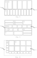
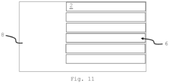
- a loading arrangement 6 is calculated by means of a control unit (not shown) or by means of software executed on the control unit, in which loading arrangement 6 plate-shaped objects 2 of the selection are to be arranged or nested on a loading surface of the loading table.
- control unit is arranged spatially separated from the production line and is also designed to control the individual components of the system according to the invention, in particular the detection unit 10, the processing units 11, the further processing unit 12, the first tilting table 15a, the second tilting table 15b, the linear conveyors 19, the delivery table 14 and/or the loading system 8.
- the plate-shaped objects 2 located in the storage unit 4 are pre-sorted on the basis of a loading sequence corresponding to the calculated loading arrangement 6, in which loading sequence the Objects 2 of the selection are to be transferred to the loading system 8 in order to produce the loading arrangement 6.
- control of the processing unit 11 and the further processing unit 12 during pre-sorting can be carried out using the software mentioned, or using another software also running on the control unit and/or using the control unit. The same applies to the removal of the plate-shaped objects 2.
- Fig. 3 represents a loading arrangement 6 comprising a selection of 17 plate-shaped objects 2. Of this selection, six plate-shaped objects 2 each have a round cover surface with the same diameter, while the remaining objects 2 have a rectangular cover surface. Here too, all plate-shaped objects 2 of the selection have the same thickness, whereby the thickness of the Fig. 3 shown plate-shaped objects 2 different from the thickness of the Fig.2 shown plate-shaped objects 2.
Landscapes
- Chemical & Material Sciences (AREA)
- Engineering & Computer Science (AREA)
- Materials Engineering (AREA)
- Organic Chemistry (AREA)
- Warehouses Or Storage Devices (AREA)
Priority Applications (4)
| Application Number | Priority Date | Filing Date | Title |
|---|---|---|---|
| EP21172144.4A EP4086206B1 (de) | 2021-05-04 | 2021-05-04 | Verfahren und system zum beladen einer wärmebehandlungseinheit |
| HUE21172144A HUE068026T2 (hu) | 2021-05-04 | 2021-05-04 | Eljárás és rendszer hõkezelõ egység betöltésére |
| ES21172144T ES2991313T3 (es) | 2021-05-04 | 2021-05-04 | Método y sistema para cargar una unidad de tratamiento térmico |
| PL21172144.4T PL4086206T3 (pl) | 2021-05-04 | 2021-05-04 | Sposób i układ do załadunku jednostki do obróbki cieplnej |
Applications Claiming Priority (1)
| Application Number | Priority Date | Filing Date | Title |
|---|---|---|---|
| EP21172144.4A EP4086206B1 (de) | 2021-05-04 | 2021-05-04 | Verfahren und system zum beladen einer wärmebehandlungseinheit |
Publications (3)
| Publication Number | Publication Date |
|---|---|
| EP4086206A1 EP4086206A1 (de) | 2022-11-09 |
| EP4086206C0 EP4086206C0 (de) | 2024-07-10 |
| EP4086206B1 true EP4086206B1 (de) | 2024-07-10 |
Family
ID=75825455
Family Applications (1)
| Application Number | Title | Priority Date | Filing Date |
|---|---|---|---|
| EP21172144.4A Active EP4086206B1 (de) | 2021-05-04 | 2021-05-04 | Verfahren und system zum beladen einer wärmebehandlungseinheit |
Country Status (4)
| Country | Link |
|---|---|
| EP (1) | EP4086206B1 (pl) |
| ES (1) | ES2991313T3 (pl) |
| HU (1) | HUE068026T2 (pl) |
| PL (1) | PL4086206T3 (pl) |
Citations (18)
| Publication number | Priority date | Publication date | Assignee | Title |
|---|---|---|---|---|
| DE3035591A1 (de) | 1979-09-24 | 1981-04-09 | Tamglass Oy, Tampere | Anlage zum tempern von glastafeln |
| EP0048334A1 (de) | 1980-09-24 | 1982-03-31 | Bystronic Maschinen AG | Vorrichtung zum Sortieren von unsortierten Glasscheiben einer Glasschneideanlage |
| EP0620171B1 (de) | 1993-04-14 | 1997-06-04 | Bystronic Maschinen AG | Anlage zum Sortieren von Plattenmaterial |
| EP0816265B1 (de) | 1996-07-03 | 2001-08-22 | Peter Lisec | Vorrichtung zum Sortieren von Glaszuschnitten |
| EP1323651A2 (de) | 2001-12-24 | 2003-07-02 | HEGLA Fahrzeug- u. Maschinenbau GmbH & Co. KG | Verfahren und Vorrichtung zum Sortieren von Glastafeln |
| US20040118160A1 (en) | 2002-12-19 | 2004-06-24 | Bystronic Maschinen Ag | Method and device for loading a glass processing installation |
| EP1284229B1 (de) | 2001-08-13 | 2005-04-27 | HEGLA Fahrzeug- u. Maschinenbau GmbH & Co. KG | Verfahren und Vorrichtung zum Bearbeiten von Glastafeln |
| EP1588962B1 (de) | 2004-04-23 | 2007-07-11 | HEGLA Fahrzeug- u. Maschinenbau GmbH & Co. KG | Beladevorrichtung zum sortierenden Beladen einer Speichereinrichtung mit plattenförmigem Material |
| WO2008020005A1 (de) | 2006-08-17 | 2008-02-21 | Albat + Wirsam Software Ag | Verfahren und vorrichtung zum zuschneiden von rohglasplatten |
| DE102009040555A1 (de) | 2009-09-08 | 2011-03-10 | Grenzebach Maschinenbau Gmbh | Verfahren und Vorrichtung zum Archivieren und /oder Zwischenlagern von Glasscheiben in Reinräumen |
| EP2543446A1 (de) | 2011-07-06 | 2013-01-09 | Klaus Knaust | Scheibensortierer |
| EP2433886B1 (de) | 2010-09-23 | 2013-01-23 | HEGLA GmbH & Co. KG | Verfahren zum Betreiben eines Zwischenspeichers für Restglastafeln sowie Zwischenspeichervorrichtung für Restglastafeln |
| KR101267002B1 (ko) | 2013-03-20 | 2013-05-30 | 이상수 | 글라스 패널 분류 이송용 흡착 이송 틸팅 플랫폼 구조체 |
| US20130202394A1 (en) | 2010-08-27 | 2013-08-08 | Kawasaki Jukogyo Kabushiki Kaisha | Plate-shaped member transfer facility |
| CN107416528A (zh) | 2017-08-31 | 2017-12-01 | 东莞市李群自动化技术有限公司 | 一种玻璃片分拣输送装置 |
| WO2019211058A1 (de) | 2018-05-04 | 2019-11-07 | Hegla Gmbh & Co. Kg | Sortierverfahren und -vorrichtung zum sortieren von plattenförmigen gegenständen, vorzugsweise glastafelzuschnitten, verfahren und vorrichtung zum herstellen von glastafelzuschnitten mit einer derartigen sortiervorrichtung |
| DE102018214131A1 (de) | 2018-08-21 | 2020-02-27 | Hegla Gmbh & Co. Kg | Shuttle zum Verfahren von Glastafeln und Speichervorrichtung mit zumindest einem derartigen Shuttle |
| WO2021185455A1 (de) | 2020-03-20 | 2021-09-23 | Hubert Haselsteiner | Beladesystem |
-
2021
- 2021-05-04 ES ES21172144T patent/ES2991313T3/es active Active
- 2021-05-04 HU HUE21172144A patent/HUE068026T2/hu unknown
- 2021-05-04 PL PL21172144.4T patent/PL4086206T3/pl unknown
- 2021-05-04 EP EP21172144.4A patent/EP4086206B1/de active Active
Patent Citations (21)
| Publication number | Priority date | Publication date | Assignee | Title |
|---|---|---|---|---|
| DE3035591A1 (de) | 1979-09-24 | 1981-04-09 | Tamglass Oy, Tampere | Anlage zum tempern von glastafeln |
| EP0048334A1 (de) | 1980-09-24 | 1982-03-31 | Bystronic Maschinen AG | Vorrichtung zum Sortieren von unsortierten Glasscheiben einer Glasschneideanlage |
| EP0620171B1 (de) | 1993-04-14 | 1997-06-04 | Bystronic Maschinen AG | Anlage zum Sortieren von Plattenmaterial |
| EP0816265B1 (de) | 1996-07-03 | 2001-08-22 | Peter Lisec | Vorrichtung zum Sortieren von Glaszuschnitten |
| EP1284229B1 (de) | 2001-08-13 | 2005-04-27 | HEGLA Fahrzeug- u. Maschinenbau GmbH & Co. KG | Verfahren und Vorrichtung zum Bearbeiten von Glastafeln |
| EP1323651A2 (de) | 2001-12-24 | 2003-07-02 | HEGLA Fahrzeug- u. Maschinenbau GmbH & Co. KG | Verfahren und Vorrichtung zum Sortieren von Glastafeln |
| DE10164071A1 (de) | 2001-12-24 | 2003-07-03 | Hegla Fahrzeug Und Maschb Gmbh | Verfahren und Vorrichtung zum Sortieren von Glastafeln |
| US20040118160A1 (en) | 2002-12-19 | 2004-06-24 | Bystronic Maschinen Ag | Method and device for loading a glass processing installation |
| EP1588962B1 (de) | 2004-04-23 | 2007-07-11 | HEGLA Fahrzeug- u. Maschinenbau GmbH & Co. KG | Beladevorrichtung zum sortierenden Beladen einer Speichereinrichtung mit plattenförmigem Material |
| WO2008020005A1 (de) | 2006-08-17 | 2008-02-21 | Albat + Wirsam Software Ag | Verfahren und vorrichtung zum zuschneiden von rohglasplatten |
| DE102009040555A1 (de) | 2009-09-08 | 2011-03-10 | Grenzebach Maschinenbau Gmbh | Verfahren und Vorrichtung zum Archivieren und /oder Zwischenlagern von Glasscheiben in Reinräumen |
| US20130202394A1 (en) | 2010-08-27 | 2013-08-08 | Kawasaki Jukogyo Kabushiki Kaisha | Plate-shaped member transfer facility |
| EP2433886B1 (de) | 2010-09-23 | 2013-01-23 | HEGLA GmbH & Co. KG | Verfahren zum Betreiben eines Zwischenspeichers für Restglastafeln sowie Zwischenspeichervorrichtung für Restglastafeln |
| EP2543446A1 (de) | 2011-07-06 | 2013-01-09 | Klaus Knaust | Scheibensortierer |
| KR101267002B1 (ko) | 2013-03-20 | 2013-05-30 | 이상수 | 글라스 패널 분류 이송용 흡착 이송 틸팅 플랫폼 구조체 |
| CN107416528A (zh) | 2017-08-31 | 2017-12-01 | 东莞市李群自动化技术有限公司 | 一种玻璃片分拣输送装置 |
| WO2019211058A1 (de) | 2018-05-04 | 2019-11-07 | Hegla Gmbh & Co. Kg | Sortierverfahren und -vorrichtung zum sortieren von plattenförmigen gegenständen, vorzugsweise glastafelzuschnitten, verfahren und vorrichtung zum herstellen von glastafelzuschnitten mit einer derartigen sortiervorrichtung |
| DE102018218141B4 (de) | 2018-05-04 | 2022-03-24 | Hegla Gmbh & Co. Kg | Sortierverfahren und -vorrichtung zum Sortieren von plattenförmigen Gegenständen, vorzugsweise Glastafelzuschnitten, Verfahren und Vorrichtung zum Herstellen von Glastafelzuschnitten mit einer derartigen Sortiervorrichtung |
| DE102018214131A1 (de) | 2018-08-21 | 2020-02-27 | Hegla Gmbh & Co. Kg | Shuttle zum Verfahren von Glastafeln und Speichervorrichtung mit zumindest einem derartigen Shuttle |
| WO2020038945A1 (de) | 2018-08-21 | 2020-02-27 | Hegla Gmbh & Co. Kg | Shuttle zum verfahren von glastafeln und speichervorrichtung mit zumindest einem derartigen shuttle |
| WO2021185455A1 (de) | 2020-03-20 | 2021-09-23 | Hubert Haselsteiner | Beladesystem |
Non-Patent Citations (39)
| Title |
|---|
| ANONYMOUS: "A+W DynOpt", A+W, 1 January 2017 (2017-01-01), XP093271296 |
| ANONYMOUS: "Geld verdienen & Energie sparen", GLASWELT, 1 June 2020 (2020-06-01), pages 96 - 97, XP093271304 |
| ANONYMOUS: "Glaston RC Series - data sheets", GLASTON, 1 September 2016 (2016-09-01), XP093271308 |
| ANONYMOUS: "NEW INNOVATION: AUTOMATIC TEMPERING FURNACE BED UNLOADING AND LOADING SYSTEM ", GLASSGLOBAL GROUP, 18 June 2020 (2020-06-18), XP093271300 |
| ANONYMOUS: "Ofenbetten optimal belegen", A+W, 1 June 2019 (2019-06-01), XP093271295 |
| ANONYMOUS: "Technical Specification TCP/IP Interface - AWDesk: 334106 ", A+W, 20 March 2025 (2025-03-20), XP093271292 |
| ANONYMOUS: "Vetrotech: Produktion von Aachen nach Würselen verlegt", GLASWELT, 17 March 2021 (2021-03-17), pages 1 - 4, XP093268995, Retrieved from the Internet <URL:https://www.glaswelt.de/glas/vetrotech-produktion-von-aachen-nach-wuerselen-verlegt> |
| D18 - Kurzer Zwischenstand (E-Mail 1 „Kurzer Zwischenstand" von Dr. Klaus Mühlhans als Antwort auf E-Mail 2 „Kurzer Zwischenstand" von Sebastian Dors) |
| D19 - Auftragsbestätigung vom 14.11.2018 |
| D20 - Email vom Dezember 2019 (E-Mail von Dr. Klaus Mühlhans an Mitarbeiter der Fa. Northglass) |
| D21 - Status Kinovation KW50 2019 (E-Mail "Status Kinovation and MAPS - Week 50" von Sebastian Dors an Mitarbeiter von Saint-Gobain) |
| D22 - Status Kinovation KW12 2020 (E-Mail "Status Kinovation and MAPS - Week 12" von Sebastian Dors an Mitarbeiter von Saint-Gobain) |
| D23 - Status Kinovation KW16 2020 (E-Mail "Status Kinovation and MAPS - Week 16" von Sebastian Dors an Mitarbeiter von Saint-Gobain) |
| D26 - Dialog (Zeitschrift) |
| D28 - NG-Email (E-Mail von Mitarbeiter von NorthGlass an Dr. Klaus Mühlhans) |
| D29 - Pflichtenheft (E-Mail von Mitarbeiter von Saint- Gobain an Sebastian Dors) |
| D37 - Facebook Beitrag Hegla-Hanic |
| D41 - Artikel aus dem Magazin GFF |
| D42 - Eidesstattliche Versicherung Dr. Schäpers |
| D44 - Website Litesentry 2018 |
| D45 - Artikel Connecting the Dots, USGlass, März 2021 |
| D46 - Angebot vom 15. Oktober 2018 |
| D47 - Layout Nr. 1650070-24 |
| D48 - Auftrag vom 10. Dezember 2018 |
| D48-1 - Übersendungsmail Bestätigung Auftrag |
| D49 - Auftragsbestätigung vom 4. Dezember 2019 |
| D50 - Layout Nr. 1650070-46 |
| D51 - Betriebsanleitung zur Sortierung 1 |
| D52 - Abnahmebestätigung für die Sortierung-Step 2 |
| D53 - Bestätigung der Endabnahme |
| D54 - Schlussrechnung |
| D54-1 - Übersendungsmail Schlussrechnung |
| D55 - Gesammelte Lieferscheine Sortierung 1 |
| D56 - Artikel aus der Zeitschrift Fenster+Glas vom Mai 2021 |
| D57 - Betriebsanleitung zur Sortierung 2 |
| D58 - Gesammelte Lieferscheine Sortierung 2 |
| D59 - Eidesstattliche Versicherung Herr Joaquim |
| HASELSTEINER GLASS SOLUTIONS AUSTRIA: "Vollautomatisches Härtebett Belade- und Entladesystem", ACS APPLIED NANO MATERIALS, AMERICAN CHEMICAL SOCIETY, vol. 4, no. 6, pages 5842 - 5853, XP093271290, ISSN: 2574-0970, Retrieved from the Internet <URL:https://www.youtube.com/watch?v=0IYFlzgcKoA> DOI: 10.1021/acsanm.1c00774 |
| LISEC AUSTRIA: "Energy Savings due to perfect furnace bed loading", XP093271288, Retrieved from the Internet <URL:https://www.youtube.com/watch?v=Th-u_hKFJgk> |
Also Published As
| Publication number | Publication date |
|---|---|
| ES2991313T3 (es) | 2024-12-03 |
| EP4086206A1 (de) | 2022-11-09 |
| HUE068026T2 (hu) | 2024-12-28 |
| EP4086206C0 (de) | 2024-07-10 |
| PL4086206T3 (pl) | 2024-10-28 |
Similar Documents
| Publication | Publication Date | Title |
|---|---|---|
| EP2998247B1 (de) | Anlage und verfahren zum bearbeiten optischer linsen | |
| EP2050523B1 (de) | Maschinelle Anordnung für die Blechbearbeitung mit einer Blechbearbeitungseinrichtung sowie mit einer Transportvorrichtung | |
| DE2925469C2 (de) | Einrichtung zur Lagerung von stangenförmigem Material und zur selbsttätigen, programmgesteuerten Versorgung einer Trennmaschine mit diesem Material | |
| DE2702725C2 (de) | Plattenaufteil-, sortier- und -stapelanlage mit mindestens einer Stapeleinrichtung | |
| EP1319634B1 (de) | Verfahren und Vorrichtung zum Teilen von Glasplatten in Zuschnitte | |
| EP3841042B1 (de) | Shuttle zum verfahren von glastafeln und speichervorrichtung mit zumindest einem derartigen shuttle | |
| EP1323651B1 (de) | Verfahren und Vorrichtung zum Sortieren von Glastafeln | |
| EP3615268B1 (de) | Bearbeitungsanlage und verfahren zum durchführen eines werkzeugwechsels an der bearbeitungsanlage | |
| EP1284229B1 (de) | Verfahren und Vorrichtung zum Bearbeiten von Glastafeln | |
| EP0453806B1 (de) | Einrichtung zum Abstapeln von aus aufgeteilten, plattenförmigen Einzelwerkstücken oder Plattenpaketen hergestellten Einzelformaten | |
| EP4086206B1 (de) | Verfahren und system zum beladen einer wärmebehandlungseinheit | |
| DE102021125391B4 (de) | Entstapelungsvorrichtung und Holzbearbeitungsanlage mit einer derartigen Entstapelungsvorrichtung | |
| EP3090848B1 (de) | Verfahren zur bearbeitung plattenförmiger werkstücke | |
| DE2106091C3 (de) | Vorrichtung zum verschachtelten, lageweisen Stapeln von profiliertem Walzgut | |
| DE2722712A1 (de) | Vorrichtung zum voruebergehenden speichern von fliesen u.dgl. | |
| DE102004012043A1 (de) | Vorrichtung und Verfahren zum lagegerechten Übergeben von quaderförmigen Waren | |
| EP3787990B1 (de) | Sortierverfahren und -vorrichtung zum sortieren von plattenförmigen gegenständen, vorzugsweise glastafelzuschnitten, verfahren und vorrichtung zum herstellen von glastafelzuschnitten mit einer derartigen sortiervorrichtung | |
| EP0264781B1 (de) | Anlage zum Aufteilen von Platten und Fördern und Stapeln der Zuschnitte | |
| DE3706122A1 (de) | Verfahren und anlage zur handhabung von werkstuecken und zu deren bearbeitung benoetigten werkzeugen an werkzeugmaschinen | |
| EP3922423B1 (de) | Werkstückzuführvorrichtung bzw. werkstückabführvorrichtung | |
| EP2810725A1 (de) | Einrichtung und Verfahren zum Abtransport bearbeiteter Werkstücke von einer Produktionsanlage | |
| DE10238461A1 (de) | Vorrichtung zum Stapeln von Formatzuschnitten mit einem verfahrbaren Gabelwagen | |
| DE20220733U1 (de) | Vorrichtung zum Bearbeiten von Glastafeln | |
| DE20122623U1 (de) | Vorrichtung zum Sortieren von Glastafeln | |
| DE8816467U1 (de) | Vorrichtung zum Abtransport von auf einem Auflagetisch einer Plattenaufteilanlage parallel zu deren Trennebene anfallenden Plattenteilstücken |
Legal Events
| Date | Code | Title | Description |
|---|---|---|---|
| PUAI | Public reference made under article 153(3) epc to a published international application that has entered the european phase |
Free format text: ORIGINAL CODE: 0009012 |
|
| STAA | Information on the status of an ep patent application or granted ep patent |
Free format text: STATUS: THE APPLICATION HAS BEEN PUBLISHED |
|
| AK | Designated contracting states |
Kind code of ref document: A1 Designated state(s): AL AT BE BG CH CY CZ DE DK EE ES FI FR GB GR HR HU IE IS IT LI LT LU LV MC MK MT NL NO PL PT RO RS SE SI SK SM TR |
|
| STAA | Information on the status of an ep patent application or granted ep patent |
Free format text: STATUS: REQUEST FOR EXAMINATION WAS MADE |
|
| 17P | Request for examination filed |
Effective date: 20230509 |
|
| RBV | Designated contracting states (corrected) |
Designated state(s): AL AT BE BG CH CY CZ DE DK EE ES FI FR GB GR HR HU IE IS IT LI LT LU LV MC MK MT NL NO PL PT RO RS SE SI SK SM TR |
|
| GRAP | Despatch of communication of intention to grant a patent |
Free format text: ORIGINAL CODE: EPIDOSNIGR1 |
|
| STAA | Information on the status of an ep patent application or granted ep patent |
Free format text: STATUS: GRANT OF PATENT IS INTENDED |
|
| RIC1 | Information provided on ipc code assigned before grant |
Ipc: C03B 35/14 20060101ALI20240212BHEP Ipc: C03B 29/08 20060101ALI20240212BHEP Ipc: B07C 5/36 20060101ALI20240212BHEP Ipc: B65G 49/06 20060101AFI20240212BHEP |
|
| INTG | Intention to grant announced |
Effective date: 20240226 |
|
| GRAS | Grant fee paid |
Free format text: ORIGINAL CODE: EPIDOSNIGR3 |
|
| GRAA | (expected) grant |
Free format text: ORIGINAL CODE: 0009210 |
|
| STAA | Information on the status of an ep patent application or granted ep patent |
Free format text: STATUS: THE PATENT HAS BEEN GRANTED |
|
| AK | Designated contracting states |
Kind code of ref document: B1 Designated state(s): AL AT BE BG CH CY CZ DE DK EE ES FI FR GB GR HR HU IE IS IT LI LT LU LV MC MK MT NL NO PL PT RO RS SE SI SK SM TR |
|
| REG | Reference to a national code |
Ref country code: CH Ref legal event code: EP |
|
| REG | Reference to a national code |
Ref country code: DE Ref legal event code: R096 Ref document number: 502021004290 Country of ref document: DE |
|
| U01 | Request for unitary effect filed |
Effective date: 20240725 |
|
| U07 | Unitary effect registered |
Designated state(s): AT BE BG DE DK EE FI FR IT LT LU LV MT NL PT RO SE SI Effective date: 20240902 |
|
| REG | Reference to a national code |
Ref country code: ES Ref legal event code: FG2A Ref document number: 2991313 Country of ref document: ES Kind code of ref document: T3 Effective date: 20241203 |
|
| REG | Reference to a national code |
Ref country code: HU Ref legal event code: AG4A Ref document number: E068026 Country of ref document: HU |
|
| PG25 | Lapsed in a contracting state [announced via postgrant information from national office to epo] |
Ref country code: NO Free format text: LAPSE BECAUSE OF FAILURE TO SUBMIT A TRANSLATION OF THE DESCRIPTION OR TO PAY THE FEE WITHIN THE PRESCRIBED TIME-LIMIT Effective date: 20241010 |
|
| PG25 | Lapsed in a contracting state [announced via postgrant information from national office to epo] |
Ref country code: GR Free format text: LAPSE BECAUSE OF FAILURE TO SUBMIT A TRANSLATION OF THE DESCRIPTION OR TO PAY THE FEE WITHIN THE PRESCRIBED TIME-LIMIT Effective date: 20241011 |
|
| PG25 | Lapsed in a contracting state [announced via postgrant information from national office to epo] |
Ref country code: IS Free format text: LAPSE BECAUSE OF FAILURE TO SUBMIT A TRANSLATION OF THE DESCRIPTION OR TO PAY THE FEE WITHIN THE PRESCRIBED TIME-LIMIT Effective date: 20241110 |
|
| PG25 | Lapsed in a contracting state [announced via postgrant information from national office to epo] |
Ref country code: HR Free format text: LAPSE BECAUSE OF FAILURE TO SUBMIT A TRANSLATION OF THE DESCRIPTION OR TO PAY THE FEE WITHIN THE PRESCRIBED TIME-LIMIT Effective date: 20240710 |
|
| PG25 | Lapsed in a contracting state [announced via postgrant information from national office to epo] |
Ref country code: RS Free format text: LAPSE BECAUSE OF FAILURE TO SUBMIT A TRANSLATION OF THE DESCRIPTION OR TO PAY THE FEE WITHIN THE PRESCRIBED TIME-LIMIT Effective date: 20241010 |
|
| PG25 | Lapsed in a contracting state [announced via postgrant information from national office to epo] |
Ref country code: RS Free format text: LAPSE BECAUSE OF FAILURE TO SUBMIT A TRANSLATION OF THE DESCRIPTION OR TO PAY THE FEE WITHIN THE PRESCRIBED TIME-LIMIT Effective date: 20241010 Ref country code: NO Free format text: LAPSE BECAUSE OF FAILURE TO SUBMIT A TRANSLATION OF THE DESCRIPTION OR TO PAY THE FEE WITHIN THE PRESCRIBED TIME-LIMIT Effective date: 20241010 Ref country code: IS Free format text: LAPSE BECAUSE OF FAILURE TO SUBMIT A TRANSLATION OF THE DESCRIPTION OR TO PAY THE FEE WITHIN THE PRESCRIBED TIME-LIMIT Effective date: 20241110 Ref country code: HR Free format text: LAPSE BECAUSE OF FAILURE TO SUBMIT A TRANSLATION OF THE DESCRIPTION OR TO PAY THE FEE WITHIN THE PRESCRIBED TIME-LIMIT Effective date: 20240710 Ref country code: GR Free format text: LAPSE BECAUSE OF FAILURE TO SUBMIT A TRANSLATION OF THE DESCRIPTION OR TO PAY THE FEE WITHIN THE PRESCRIBED TIME-LIMIT Effective date: 20241011 |
|
| PLBI | Opposition filed |
Free format text: ORIGINAL CODE: 0009260 |
|
| PG25 | Lapsed in a contracting state [announced via postgrant information from national office to epo] |
Ref country code: SM Free format text: LAPSE BECAUSE OF FAILURE TO SUBMIT A TRANSLATION OF THE DESCRIPTION OR TO PAY THE FEE WITHIN THE PRESCRIBED TIME-LIMIT Effective date: 20240710 |
|
| PLBI | Opposition filed |
Free format text: ORIGINAL CODE: 0009260 |
|
| PG25 | Lapsed in a contracting state [announced via postgrant information from national office to epo] |
Ref country code: SK Free format text: LAPSE BECAUSE OF FAILURE TO SUBMIT A TRANSLATION OF THE DESCRIPTION OR TO PAY THE FEE WITHIN THE PRESCRIBED TIME-LIMIT Effective date: 20240710 |
|
| 26 | Opposition filed |
Opponent name: BENTELER MASCHINENBAU GMBH Effective date: 20250401 |
|
| PLAX | Notice of opposition and request to file observation + time limit sent |
Free format text: ORIGINAL CODE: EPIDOSNOBS2 |
|
| 26 | Opposition filed |
Opponent name: HEGLA GMBH & CO. KG Effective date: 20250410 Opponent name: A+W SOFTWARE GMBH Effective date: 20250410 Opponent name: LISEC AUSTRIA GMBH Effective date: 20250410 |
|
| U1O | Appointed representative for the unitary patent procedure deleted after the registration of the unitary effect | ||
| REG | Reference to a national code |
Ref country code: CH Ref legal event code: H13 Free format text: ST27 STATUS EVENT CODE: U-0-0-H10-H13 (AS PROVIDED BY THE NATIONAL OFFICE) Effective date: 20251223 |
|
| U90 | Renewal fees not paid: noting of loss of rights |
Free format text: RENEWAL FEE NOT PAID FOR YEAR 05 Effective date: 20251217 |
|
| PG25 | Lapsed in a contracting state [announced via postgrant information from national office to epo] |
Ref country code: CH Free format text: LAPSE BECAUSE OF NON-PAYMENT OF DUE FEES Effective date: 20250531 |
|
| PG25 | Lapsed in a contracting state [announced via postgrant information from national office to epo] |
Ref country code: CZ Free format text: LAPSE BECAUSE OF NON-PAYMENT OF DUE FEES Effective date: 20250504 |
|
| GBPC | Gb: european patent ceased through non-payment of renewal fee |
Effective date: 20250504 |
|
| PG25 | Lapsed in a contracting state [announced via postgrant information from national office to epo] |
Ref country code: MC Free format text: LAPSE BECAUSE OF FAILURE TO SUBMIT A TRANSLATION OF THE DESCRIPTION OR TO PAY THE FEE WITHIN THE PRESCRIBED TIME-LIMIT Effective date: 20240710 |
|
| RDAF | Communication despatched that patent is revoked |
Free format text: ORIGINAL CODE: EPIDOSNREV1 |