EP4085207B1 - Rückschlagventil mit konformer aufnahme - Google Patents
Rückschlagventil mit konformer aufnahme Download PDFInfo
- Publication number
- EP4085207B1 EP4085207B1 EP20853585.6A EP20853585A EP4085207B1 EP 4085207 B1 EP4085207 B1 EP 4085207B1 EP 20853585 A EP20853585 A EP 20853585A EP 4085207 B1 EP4085207 B1 EP 4085207B1
- Authority
- EP
- European Patent Office
- Prior art keywords
- annular
- seat
- valve
- cover
- seat ring
- Prior art date
- Legal status (The legal status is an assumption and is not a legal conclusion. Google has not performed a legal analysis and makes no representation as to the accuracy of the status listed.)
- Active
Links
Images


Classifications
-
- F—MECHANICAL ENGINEERING; LIGHTING; HEATING; WEAPONS; BLASTING
- F16—ENGINEERING ELEMENTS AND UNITS; GENERAL MEASURES FOR PRODUCING AND MAINTAINING EFFECTIVE FUNCTIONING OF MACHINES OR INSTALLATIONS; THERMAL INSULATION IN GENERAL
- F16K—VALVES; TAPS; COCKS; ACTUATING-FLOATS; DEVICES FOR VENTING OR AERATING
- F16K15/00—Check valves
- F16K15/02—Check valves with guided rigid valve members
- F16K15/025—Check valves with guided rigid valve members the valve being loaded by a spring
- F16K15/026—Check valves with guided rigid valve members the valve being loaded by a spring the valve member being a movable body around which the medium flows when the valve is open
-
- F—MECHANICAL ENGINEERING; LIGHTING; HEATING; WEAPONS; BLASTING
- F16—ENGINEERING ELEMENTS AND UNITS; GENERAL MEASURES FOR PRODUCING AND MAINTAINING EFFECTIVE FUNCTIONING OF MACHINES OR INSTALLATIONS; THERMAL INSULATION IN GENERAL
- F16K—VALVES; TAPS; COCKS; ACTUATING-FLOATS; DEVICES FOR VENTING OR AERATING
- F16K1/00—Lift valves or globe valves, i.e. cut-off apparatus with closure members having at least a component of their opening and closing motion perpendicular to the closing faces
- F16K1/32—Details
- F16K1/34—Cutting-off parts, e.g. valve members, seats
- F16K1/42—Valve seats
- F16K1/425—Attachment of the seat to the housing by plastical deformation, e.g. valve seat or housing being plastically deformed during mounting
-
- F—MECHANICAL ENGINEERING; LIGHTING; HEATING; WEAPONS; BLASTING
- F16—ENGINEERING ELEMENTS AND UNITS; GENERAL MEASURES FOR PRODUCING AND MAINTAINING EFFECTIVE FUNCTIONING OF MACHINES OR INSTALLATIONS; THERMAL INSULATION IN GENERAL
- F16K—VALVES; TAPS; COCKS; ACTUATING-FLOATS; DEVICES FOR VENTING OR AERATING
- F16K15/00—Check valves
- F16K15/18—Check valves with actuating mechanism; Combined check valves and actuated valves
-
- F—MECHANICAL ENGINEERING; LIGHTING; HEATING; WEAPONS; BLASTING
- F16—ENGINEERING ELEMENTS AND UNITS; GENERAL MEASURES FOR PRODUCING AND MAINTAINING EFFECTIVE FUNCTIONING OF MACHINES OR INSTALLATIONS; THERMAL INSULATION IN GENERAL
- F16K—VALVES; TAPS; COCKS; ACTUATING-FLOATS; DEVICES FOR VENTING OR AERATING
- F16K27/00—Construction of housing; Use of materials therefor
- F16K27/02—Construction of housing; Use of materials therefor of lift valves
-
- F—MECHANICAL ENGINEERING; LIGHTING; HEATING; WEAPONS; BLASTING
- F16—ENGINEERING ELEMENTS AND UNITS; GENERAL MEASURES FOR PRODUCING AND MAINTAINING EFFECTIVE FUNCTIONING OF MACHINES OR INSTALLATIONS; THERMAL INSULATION IN GENERAL
- F16K—VALVES; TAPS; COCKS; ACTUATING-FLOATS; DEVICES FOR VENTING OR AERATING
- F16K39/00—Devices for relieving the pressure on the sealing faces
- F16K39/02—Devices for relieving the pressure on the sealing faces for lift valves
- F16K39/022—Devices for relieving the pressure on the sealing faces for lift valves using balancing surfaces
-
- F—MECHANICAL ENGINEERING; LIGHTING; HEATING; WEAPONS; BLASTING
- F16—ENGINEERING ELEMENTS AND UNITS; GENERAL MEASURES FOR PRODUCING AND MAINTAINING EFFECTIVE FUNCTIONING OF MACHINES OR INSTALLATIONS; THERMAL INSULATION IN GENERAL
- F16K—VALVES; TAPS; COCKS; ACTUATING-FLOATS; DEVICES FOR VENTING OR AERATING
- F16K1/00—Lift valves or globe valves, i.e. cut-off apparatus with closure members having at least a component of their opening and closing motion perpendicular to the closing faces
- F16K1/32—Details
- F16K1/34—Cutting-off parts, e.g. valve members, seats
- F16K1/42—Valve seats
-
- F—MECHANICAL ENGINEERING; LIGHTING; HEATING; WEAPONS; BLASTING
- F16—ENGINEERING ELEMENTS AND UNITS; GENERAL MEASURES FOR PRODUCING AND MAINTAINING EFFECTIVE FUNCTIONING OF MACHINES OR INSTALLATIONS; THERMAL INSULATION IN GENERAL
- F16K—VALVES; TAPS; COCKS; ACTUATING-FLOATS; DEVICES FOR VENTING OR AERATING
- F16K31/00—Actuating devices; Operating means; Releasing devices
- F16K31/02—Actuating devices; Operating means; Releasing devices electric; magnetic
- F16K31/06—Actuating devices; Operating means; Releasing devices electric; magnetic using a magnet, e.g. diaphragm valves, cutting off by means of a liquid
- F16K31/0644—One-way valve
- F16K31/0655—Lift valves
Definitions
- the present disclosure relates to the field of valves, more particularly to control valves used in fluid based control circuits used to initiate and control the operation of fluid operated control components and other fluid operated components, for example pressure relief and check valves connected to a fluid circuit, the valve configured to move from a closed to an open position and allow fluid in the circuit to pass therethrough, as well as be piloted open to vent a pressure downstream of the valve, i.e., at the valve outlet.
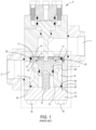
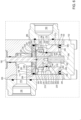
- Certain fluid valves for example a prior check valve 4 as shown in Figures 1 and 2 , which is used in fluid circuits which control the operation of, or operate, fluid controlled or operated equipment, include a first fluid port 1 functionable as an upstream inlet, a second fluid port 2 functionable as a downstream outlet, and, when the pressure in the first fluid port 1 exceeds a predefined pressure, also known as the "cracking pressure", a recessed annular seal sleeve 3 having a seat contact recessed from the outer circumferential wall thereof actuates to selectively communicate fluid and pressure between the first fluid port and the second fluid port.
- the valve 4 can operate as a check valve.
- these valves 4 include a main body 5 having a central bore 6, a counterbore 7 extending inwardly of an outer wall 8 of the main body 5 and terminating at an annular seat face 9 , and a cap 10 extending over the outer wall 8 into which the counterbore extends and which seals off the counterbore 7.
- the cap 10 includes a boss 23 extending inwardly of the counterbore 7 and terminating at a boss face 24.
- a seat ring 11 is disposed within the counterbore 7 and against the annular seat face 9, and a cage 12 functioning as a cage extends between the boss face 24 of the cap 10 and the seat ring 11.
- the recessed annular seal sleeve 3 is engaged against the back side 13 of the seat ring 11 opposite to the front side 14 thereof facing the annular seat face 9, and a spring 15 extends between the cap 10 and the recessed annular seal sleeve 3 to bias the recessed annular seal sleeve 3 against the back side 13 of the seat ring 11.
- the recessed annular seal sleeve 3 faces the portion of the central bore 6 of the body which is fluidly coupled to the first fluid port 1. When the pressure in the first fluid port 1 exceeds the cracking pressure, the recessed annular seal sleeve 3 backs away from the back side 13 of the seat ring 11, and allows fluid and pressure communication between the first fluid port 1 and the second fluid port 2.
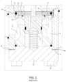
- the seat ring 11 includes a circumferential outer surface 19 generally of the same geometry of the counterbore inner wall 20, into which extends a circumferential seal groove 21 having a seal ring, such as an O-ring 22 therein.
- the O-ring 22 contacts the base of the circumferential seal groove 21 and the counterbore inner wall 20, and the width of the O-ring 22, and thus of the circumferential seal groove 21, is dictated by the maximum expected pressure difference between the first fluid port 1 and the second fluid port 2, plus a safety factor, over the installed life of the valve 4.
- the thickness "t" of the annular projections or flanks of the seat ring 11 between the opposed front side 14 or back side 13 of the seat ring 11 and the circumferential seal groove 21 are likewise selected to ensure that the seat ring 11 has sufficient strength to withstand the maximum expected pressure difference between the first fluid port 1 and the second fluid port 2, plus a safety factor without failing and allowing the O-ring 22 to become free of the circumferential seal groove 21 and thereby allow uncontrolled flow of fluid and pressure between the between the first fluid port 1 and the second fluid port 2. Additionally, this requires the seat ring 11 be manufactured of a relatively rigid plastic material, such as Delrin ® 511P or a PEEK material.
- the cage 12 is sized to bias the seat ring 11 against the annular seat face 9 upon assembly of the valve 4.
- the seat ring 11 is a solid right annular body, configured to withstand extremes of pressure, and has limited compressibility.
- the boss 23, and thus boss face 24 on the cap 10 which is connected to the main body 4 by a plurality of fasteners extending through opening therethrough (not shown) and corresponding threaded openings (not shown) into which threaded fasteners are secured, 16 presses an annular face 17 of the cage 12 against the back side 13 of the seat ring 11 and thus presses the seat ring 11 against the annular seat face 9.
- a purposefully created tolerance stack gap 18a ( Figure 2 ) is present between the inner surface 18 of the cap 10 and the adjacent outer surface 8 of the main body 5 surrounding the counterbore 7, i.e., at all ranges of the tolerances of these parts, the tolerance stack gap 18a is present.
- the valve assembler cannot ensure that the annular face 17 of the cage 12 biases the seat ring 11 against the annular seat face 9 such as when the seat ring 11, cage 12 and height of the boss 23 are at their minimum dimensions and the counterbore 7 is at its maximum depth dimension, but still within allowed dimensional tolerances.
- the gap is purposefully present to allow the assembler of the valve to a visual indicator on the exterior of the valve that the seat ring 11 is properly pushed or biased physically annular seat face 9. If the inner surface 18 of the cap 10 is secured against the base of the outer wall 8, one is unsure whether the cage 12 is actually biased against the seat ring 11 and simultaneously biasing the seat ring 11 against the annular seat face 9.
- this tolerance stack gap 18a is present between the inner surface 18 of the cap 10 and the base of the outer wall 8, the ambient fluids around the installed location of the valve 4 are able to enter into the tolerance stack gap, and where the valve is located in a corrosive environment such as an offshore or subsea environment and exposed to seawater, cause corrosion, and eventually, stress corrosion cracking of the cap 10 or valve body 5, resulting in failure of the valve 4 and the need to replace the valve 4.
- the failure of the valve 4 will affect the integrity of the fluid circuit to which it is connected, for example a fluid control circuit for an offshore or subsea blowout preventer, the integrity of the ability to close the rams of the blowout preventer can be affected. Therefore, the valves 4 of this construct may need to be prematurely replaced prior to the expiration of their useful life and well before the onset of stress corrosion cracking, well before the likelihood of valve failure.
- US Publication 2012/0248358A1 discloses a solenoid having an annular magnet structure held within a body by a cover, and the magnet structure is surrounded on three sides by a seal.
- the seal includes an extending lip on the end thereof distal to the cover, and the lip contacts the interior surface of the body.
- KR Publication 10 2005 0045760 A discloses a solenoid having an annular magnet structure held within a body by a cover, and the magnet structure is surrounded on three sides by a seal.
- the seal includes an extending lip on the end thereof distal to the cover, and the lip contacts the interior surface of the body.
- JP Publication 2019086086 A discloses a solenoid having an annular magnet structure held within a body by a cover, and the magnet structure is surrounded on three sides by a seal.
- the seal includes an extending lip on the end thereof distal to the cover, and the lip contacts the interior surface of the body.
- US Patent number 4,793,590 A discloses a valve according to the preamble of claim 1 and having a pilot piston which is disposed in a pilot piston bore.
- An end cap includes a boss extending inwardly of the pilot piston bore.
- DE Publication 10 2018 107 053 A1 discloses a fuel pump having an internal member including a projecting portion, a portion of which surrounds a fuel passage, within which a piston reciprocates.
- US Patent number 9,719,600 B2 discloses a valve including a body having a first inlet, a second inlet and an outlet.
- the valve further includes a shuttle disposed in the body.
- the shuttle is movable within the body between a first position and a second position, wherein the first inlet is open and the second inlet is closed when the shuttle is in the first position, and wherein the first inlet is closed and the second inlet is open when the shuttle is in the second position.
- the valve includes a non-metallic seal assembly disposed adjacent each inlet.
- a valve includes a valve body including a first fluid port opening from the valve body, a second fluid port opening from the valve body, and an interior passage selectively fluidly connecting the first fluid port and the second fluid port, a bore extending inwardly of a first wall of the valve body and having an annular first seat securement surface extending around the an interior passage intermediate of the first fluid port and the second fluid port, a cage disposed in the bore, the cage having an annular second seat securement surface and an opposed first annular surface, the annular second seat securement surface facing the annular first seat securement surface, a cover extending over the first wall of the valve body and the opening of the bore thereof, the cover including a cage engagement surface contacting the first annular surface, and an annular seat having a main body having an opening therethrough and a first seat surface facing and contacting the annular first seat securement surface of the valve body and a second seat surface, facing away from the first seat surface, the second seat surface comprising a first annular region having a first elevation and a second annular region
- a valve in an additional aspect, not forming part of the claimed invention, includes a valve body including a first fluid port opening from the valve body, a second fluid port opening from the valve body, and an interior passage selectively fluidly connecting the first fluid port and the second fluid port, a bore extending inwardly of a first wall of the valve body and having an annular first seat securement surface extending around the an interior passage intermediate of the first fluid port and the second fluid port, a cage disposed in the bore, the cage having an annular second seat securement surface and an opposed first annular surface, the annular second seat securement surface facing the annular first seat securement surface, a cover extending over the first wall of the valve body and the opening of the bore thereof, the cover including a cage engagement surface contacting the first annular surface, and an annular seat having a main body having an opening therethrough and a first seat surface facing and contacting the annular first seat securement surface of the valve body and a second seat surface, facing away from the first seat surface, the second seat surface comprising a first
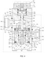
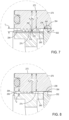
- a valve here configured as a non-gapped check valve 100 functional as, for example, a pressure relief valve, is provided, wherein the first cover 102 corresponding to the cap 10 of the valve 4 of Figures 1 and 2 comes into contact with the adjacent lower cover wall 106 of the body 104 of the non-gapped check valve 100, such that no gap is present between the first cover 102 and the adjacent annular cover wall 106 of the body 104, resulting in reduced corrosion of the components and a longer useable valve lifetime.
- this capability is provided by use of a conforming seat ring 108 ( Figure 4 ) having regions of different compressibility.
- the conforming seat ring 108 includes a plurality of projections 110 extending therefrom on the side thereof facing away from the annular seat wall 113 (corresponding to the annular seat ledge 9 of valve 4) of the non-gapped check valve 100, which projections 110 are compressible to provide a physical or dimensional relief for the tolerance stack of the valve components, ensuring that the surface of the first cover 102 abuts and contacts the adjacent annular cover wall 106 of the body 104 over the range of the tolerance stack of the interior components of the valve and the cage 210 of the non-gapped check valve 100 is in contact with the conforming seat ring 108, and the conforming seat ring 108 is thus biased into contact with the annular seat wall 113 when the non-gapped check valve 100 is assembled, over the entire range of the dimensional tolerance of the components thereof.
- the projections 110 may be in a limited annular region or radial span of the cage facing side of the conforming seat ring 108, and thus the conforming seat ring 108 has different compressibility at different annular regions thereof. Additionally, the annular region of lower compressibility may be considered to be at a different elevation of the conforming seat ring 108, i.e., extending outwardly from the annular cap facing surface (second annular face 274) of the conforming set ring, as well as in a different annular region of the annular cap facing surface (second annular face 274) of the conforming seat ring 108.
- the entire conforming seat ring 108 is composed of the same material having the same material properties, including the projections 110 thereof.
- the projections 110 extend outwardly from the second annular face 274 of the conforming seat ring 108 and are spaced from one another, both radially and, in part, circumferentially, across the second annular face 274.
- the projections 110, and the open spaces between them, together in aggregate form a region that has greater compressibility, in other words is more readily compressed, than that of the remaining bulk of the conforming seat ring 108.
- the volume or bulk of the projections 110 can, when pressed inwardly of the conforming seat ring 108, deform in a radial direction into the space between the adjacent projections 110 in the radial direction of the conforming seat ring 108 second annular surface 274, and thus have greater compressibility than that of the remaining bulk of the conforming seat ring 108.
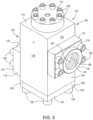
- the non-gapped check valve 100 similarly to the non-gapped check valve 100 of Figures 1 and 2 , the non-gapped check valve 100 includes the body 104 manufactured, when for subsea service, of for example stainless steel, duplex stainless steel, or CRA (nickel alloy), having a generally rectangular outer contour provided of four generally planer outer faces, first through fourth outer surfaces 120, 122, 124 and 126, bounded at their opposed ends by a lower cover wall 106 and an upper cover wall 114.
- the body 104 manufactured, when for subsea service, of for example stainless steel, duplex stainless steel, or CRA (nickel alloy), having a generally rectangular outer contour provided of four generally planer outer faces, first through fourth outer surfaces 120, 122, 124 and 126, bounded at their opposed ends by a lower cover wall 106 and an upper cover wall 114.
- CRA nickel alloy
- a first cover 102 extends over the lower cover wall 106 ( Figure 4 ) , a third adaptor 112 extends partially over the second cover wall 114, a first adaptor 116 extend spatially over the first outer surface 120 and a second adaptor 118 extends partially over the fourth outer face 124.
- first cover 102, and first, second and third adaptors 116, 118, 112 are connected the body 104 by a fastening paradigm, here by a plurality of threaded fasteners 128 extending through openings in the corresponding one of the first cover 102, and the first, second and third adaptors 116, 118, 112 and into corresponding threaded apertures provided therefor (not shown) extending inwardly of the first and fourth outer surfaces 120 and 126, and the lower cover wall 106 and an upper cover wall 114.
- a fastening paradigm here by a plurality of threaded fasteners 128 extending through openings in the corresponding one of the first cover 102, and the first, second and third adaptors 116, 118, 112 and into corresponding threaded apertures provided therefor (not shown) extending inwardly of the first and fourth outer surfaces 120 and 126, and the lower cover wall 106 and an upper cover wall 114.
- first cover 102 includes a main body 130 having a generally rectangular perimeter wall 132 having generally the same dimensions as the rectangular, in section, body 104, and first cover boss 134 extending therefrom and inwardly of a counterbore 136 extending inwardly of the cover wall 106 of the body 104.
- a first annular boss 138 extends from the counterbore facing side of the main body 130 of the first cover 102 adjacent the outer perimeter of the first cover boss 134.
- An annular circumferential limit wall 154 extends circumferentially around the first cover boss 134 and is engaged against the lower cover wall 106 of the body 104 of the non-gapped check valve 100 with no gap therebetween.
- a first cover outer seal groove 144 extends inwardly of the outer first cover wall 140 and a first cover seal ring 184 is located therein and is squeezed between the base 146 of the first cover outer seal groove 144 and the facing inner surface of the inner counterbore wall 142.
- a second first cover boss 148 extends from the main body 130 in the direction opposed to the first cover boss 134.
- a spring bore 150 here configured as a generally right cylindrical blind bore or blind hole, extends inwardly of a first cover loading surface 152 extending within the inner circumference of the first cover boss 138 and generally centered thereon.
- the first cover 102 also includes a first cover loading surface 152 which is generally circular, and is bounded at its outer circumference by an inner annular guide wall 266 which forms the inner circumferential limit of the first annular boss 138 and the outer circumferential limit of the first cover loading surface 152, and the first annular boss 138 also includes an annular valve inwardly facing surface 268 extending from the terminus of inner annular guide wall 266, distal to the first cover loading surface 152, to the outer first cover wall 140.
- the third adaptor 112 includes a third adaptor cover main body 156 having a third adaptor cover boss 158 extending therefrom and into a piston bore 160 extending inwardly of the second cover wall 114 of the body 104.
- the third adaptor cover boss 158 is a generally right annular member having an third adaptor boss outer circumferential surface 162 having a diameter on the order of 0.003 to 0.006 inches (0.076 to 0.15 mm) less than the diameter of the piston bore 160 and terminating in a generally circular inwardly facing surface 164.
- a generally circular outer third adaptor face 166 is located on the third adaptor 112 on the side thereof opposed to the inwardly facing surface 164.
- An actuator bore 168 extends through the third adaptor 112 with opposed openings thereof generally centered in the inwardly facing surface 164 and the outer third adaptor face 166.
- the third adaptor 112 is connected to the upper cover wall 114 by plurality of threaded fasteners 128 extending through openings (not shown) in the third adaptor 112 and corresponding threaded apertures provided therefor (not shown) extending inwardly of the outer cover wall 114 and body 104.
- First and second adaptors 116, 118 are each configured to receive a threaded nipple therein, and each includes an adaptor body 170 having a generally rectangular outer perimeter and a generally circular, in section, female receiver portion 172 extending therefrom in the direction away from the body 104, a lower rectangular body 174 and an annular outer guide surface 176.
- a first bore 178 extends inwardly of the lower rectangular body 174, and a second threaded bore 180 having an inner circumferential surface configured with threads 182 fluidly connected to the first bore 178 inwardly of the adaptor body 170.
- first and second adaptors 116, 118 are connected to their respective first and fourth outer surfaces 120, 126, by a plurality of threaded fasteners 128 extending through openings (not shown) in the adaptor bodies 170 of the first and second adaptors 116, 118 and corresponding threaded apertures provided therefor (not shown) extending inwardly of the respective first and fourth outer surfaces 120, 126 and body 104.
- An annular seal groove 186 extends inwardly of the base of the lower rectangular body 174 and around the opening of the first bore 178 into the lower rectangular body 174, and a seal ring 184 such as an O-ring is received therein and seals against the base of the annular seal groove 186 and the adjacent corresponding ones of the first and fourth outer surfaces 120, 126 of the body 104.
- Body 104 is configured with fluid volumes therein, and with active components which are actuable in response to changes in pressure in at least one of the fluid volumes therein, to change a position or state of the actuable components to enable selective communication between the first bore 178 and the second threaded bore 180 of the first adaptor 116 and the first bore 178 and the second threaded bore 180 of the second adaptor 118.
- the non-gapped check valve 100 is configured to allow substantially free fluid flow from the first bore 178 to the second bore 180 when the pressure differential therebetween exceeds the cracking pressure of the valve, and block communication between the first bore 178 and the second threaded bore 180 of the first adaptor 116 and the first bore 178 and the second bore 180 of the second adaptor 118 unless the pressure in the first bore 178 and the second bore 180 of the first adaptor 116 exceeds that cracking pressure, for example a pressure difference of 100 p.s.i.
- the cracking pressure is a function of the difference between the pressures in the first and second bores 178, 180 and the spring constant "k" of a spring 194 tending to push and thus seat the modified seal sleeve 196 against the conforming seat ring 108, such as the position thereof of Figure 4 .
- the counterbore 136 extending inwardly of the lower cover wall 106 terminates within the body at an annular seat wall113 which circumscribes a central flow passage 190 within the body 104, and the central flow passage 190 extends therefrom in the direction of the upper cover wall 114, which in turn terminates at an annular rod ledge 188 circumscribing a rod alignment passage 192 extending from its opening through the annular rod ledge into the piston bore 160 extending inwardly of the upper cover wall 114.
- the pressure activated active components include a modified seal sleeve 196, the modified seal sleeve 196 operating as a seal sleeve having a similar function to that of the annular seal sleeve 3 of the valve of Figures 1 and 2 herein.
- the spring 194 includes a lower portion of which bears against the base 195 of the spring bore 150 extending inwardly of the first cover 102 and an upper portion 200 which extends into engagement with the base 198 of a piston spring bore 201 extending inwardly of the first cover loading surface 152 of the lower face 204 of the modified seal sleeve 196, generally centered across the surface thereof.
- Central flow passage 190 is in fluid communication with the first bore 178 and thus the second bore 180 of the first adaptor 116 through a first cross passage 206 in the body 104 extending therebetween.
- the counterbore 136 is in communication with the first bore 178 and second threaded bore 180 of the second adaptor 118 through a second cross passage 240 in the body 104 extending therebetween.
- Conforming seat ring 108 is disposed against, and configured to seal against, annular seat wall 113, and the modified seal sleeve 196 is selectively moveable, based on the difference in pressure between the pressures in the first bores 178 and second threaded bores 180 of the first and second adaptors 116, 118 and the spring constant of the spring 194, to either seal against the conforming seat ring 108 and thereby prevent fluid communication between the central flow passage 190 and the counterbore 136 and thus between the first bores 178 and second threaded bores 180 of the first and second adaptors 116, 118, or to move away from the conforming seat ring 108 under the influence of a sufficiently higher pressure in the first bore 178 and second threaded bore 180 of the first adaptor 116 as compared to the pressure in the first bore 178 and second threaded bore 180 of the second adaptor 118 to compress the spring 194 and thereby cause the modified seal sleeve 196 to move away from the conforming seat ring 108.
- the modified seal sleeve 196 seats against an annular region 290 of the facing annular surface of the conforming seat ring 108, thereby preventing flow from the first bore 178 of the second adaptor 118 to the first bore 178 of the first adaptor 116, unless this status is physically overridden, or, the pressure in the first bore 178 of the first adaptor 116 exceeds the pressure in the first bore of the second adaptor 118 by a value sufficient to overcome the force of the spring 194 tending to push the modified seal sleeve 196 seats against an annular region 290 of the facing annular surface of the conforming seat ring 108.
- a cage 210 is disposed in the counterbore 136, and includes a central aperture 212 therein extending in the direction between the conforming seat ring 108 and the first cover 102.
- Cage 210 is configured to provide a cylindrical guide surface 214 surrounding the inner bore thereof, which is configured to allow the modified seal sleeve 196 to move linearly toward and away from the conforming seat ring 108, and guide and align this movement.
- the modified seal sleeve 196 includes a first minor diameter portion 216 having a generally right cylindrical seal sleeve outer surface 219 extending in the direction between the conforming seat ring 108 and the first cover 102, wherein the diameter of the cylindrical seal sleeve outer surface 219 of the minor diameter portion 216 is 0.003 to 0.004 inches (0.076 to 0.1 mm) smaller than the corresponding diameter of the cylindrical guide surface 214.
- a minor diameter portion seal groove 220 extends circumferentially around, and inwardly of, the seal sleeve outer surface 219, and includes therein a pair of seal sleeve back up rings 222 and a seal sleeve seal ring 224 interposed between the seal sleeve back up rings 222, and contacting both the base of the minor diameter portion seal groove 220 and the cylindrical guide surface 214 to seal the space between the minor diameter portion seal groove 220 and the cylindrical guide surface 214 to prevent fluid flow there past or therethrough.
- Modified seal sleeve 196 further includes a seal sleeve major diameter portion 226 extending integrally from the first minor diameter portion 216 as an integral extension thereof and in the direction of the conforming seat ring 108.
- Seal sleeve major diameter portion includes an annular extending portion 228 extending integrally from the first minor diameter portion 216 as an integral extension thereof in the direction of the conforming seat ring 108 terminating in an annular seal face 234, which surrounds a central recess 230.
- the outer surface of the annular extending portion 228 includes an outer cylindrical seal sleeve major diameter outer wall 232, and a connecting ledge 236 connects the outer cylindrical seal sleeve major diameter outer wall 232 and the seal sleeve outer surface 219.
- the central recess 230 includes a central recess surface 238, and a flow balance passage 241 opens thereinto and extends through the body of the modified seal sleeve 196 to open through the base 198 of lower piston spring bore 201 of the modified seal sleeve 196.
- Cage 210 is configured to guide the modified seal sleeve 196 to be generally centered along the centerline 256 of the cage 210 during movement thereof toward and away from conforming seat ring 108, to prevent the modified seal sleeve 196 from cocking, or having its longitudinal axis greatly deviate from that of centerline 256, as it moves.
- Cage 210 includes a first outer cage surface 242 disposed adjacent to the first cover 102 having a diameter on the order of 0.003 to 0.004 inches (0.076 to 0.1 mm) less than the corresponding inner circumferential surface 246 of the counterbore 136, and a second outer cage surface 244 disposed adjacent to the conforming seat ring 108 and having a diameter on the order of 0.003 to 0.004 inches (0.076 to 0.1 mm) less than the corresponding inner circumferential surface 246 of the counterbore 136, a cage lower annular surface 248 facing the first cover 102, a cage upper annular surface 250 facing, and contacting, the conforming seat ring 108, an annular recess 252 extending inwardly of and between the first and second outer cage surfaces 242, 244, and an upper guide surface 254 having an inner diameter on the order of 0.003 to 0.004 inches (0.076 to 0.1 mm) greater than that of the outer cylindrical seal sleeve major diameter outer wall 232.
- cage 210 includes a circumferential recess 258 extending inwardly of the lower annular surface 248 and the first outer cage surface 242 thereof.
- Circumferential recess has a lower annular wall 260 extending inwardly of the cage 210 and facing the first cover 102 and terminating at a circumferential pilot wall 261 extending therefrom to the lower annular surface 248 of the cage 210.
- a circumferential seal gland 262 extends inwardly of the pilot wall 261 generally midway between the lower annular wall 260 and the lower annular surface 248 of the cage 210.
- a seal ring 264 for example an O-ring, is received in the circumferential seal gland 262, and seals against the base of the circumferential seal gland 262 and the inner annular guide wall 266 of the first annular boss 138 to seal off fluid flow and communication in any gap between the inner annular guide wall 266 of the first annular boss 138 and the pilot wall 261.
- conforming seat ring 108 has an annular ring shaped body 270, including a first annular face 272, here facing the annular seat wall 113 of the valve body 104, an opposed second annular face 274 here facing the cage upper annular surface 250, the second annular face 274 having a series of the projections 110 extending therefrom and which extend outwardly from an inner annular region 290 of the second annular face 274.
- Ring shaped body 270 further includes an inner, generally circular, opening 276 therethrough having an inner circumferential wall 278 terminating at its opposed sides (first and second annular faces 272, 274) at opposed first and second frustoconical faces 280, 281 ( Figure 6 ) and an outer circumferential wall 282.
- Outer circumferential wall includes a circumferential gland 286 extending thereinto, within which a conforming seat ring outer seal 288 ( Figure 6 ) is positioned to seal between the base of the circumferential gland 286 and the inner counterbore wall 142 to prevent fluid leakage or fluid communication in any gap between the inner counterbore wall 142 and the outer circumferential wall 282 of the conforming seat ring 108.
- the second annular face 274 of the conforming seat ring 108 includes the inner annular region 290 presenting as a generally flat or planar annular region extending radially outwardly of the intersection thereof with the first frustoconical face 280, an outer annular region 294 presenting as a generally flat or planar annular region extending radially inwardly of the outer circumferential wall 282, and an annular intermediate region 294, from which the projections 110 project, extending therebetween.
- inner annular region 290 and outer annular region 294 are generally coplanar when the conforming seat ring 108 is in a free state, i.e., when the conforming seat ring 108 is in an unbiased or un-squeezed state prior to the conforming seat ring 108 being pressed by the cage 210 against annular seat wall113.
- the inner annular region 290, outer annular region 294 and intermediate annular region 292 of the conforming seal sleeve196 are located, and sized, with respect to the cage 210 and the modified seal sleeve 196, to ensure that the projections 110 contact the cage upper annular surface 250, and the connecting ledge 236 of the modified seal sleeve 196 can contact only the inner annular region 290 of conforming seat ring 108.
- the central flow passage 190 here is a generally circular in cross-section passage having a diameter D 1
- first frustoconical surface 280 has a maximum diameter, at the intersection thereof with inner annular region 290, of D 2 which is greater than diameter D 1
- inner circumferential wall 278 has a diameter D 3 which is greater than D 1 but less than D 2
- the inner annular region 290 extends from diameter D 4 which is generally equal to diameter D 2 to diameter D 7 , at which diameter the intermediate annular region 292 begins.
- Connecting ledge 236 has an inner diameter D 5 greater than both diameter D 4 and diameter D 1 and an outer diameter D 6 greater than inner diameter D 5 and less than diameter D 7 , all diameters D1 to D 7 are centered on centerline C of the conforming seat ring 108.
- the inner diameter of the upper guide surface 254 of the cage 210 is slightly larger than the outer diameter D 6 of the connecting ledge 236, and it extends outwardly therefrom to approximately the same diameter as the outer diameter of the conforming seat ring 108, thereby ensuring that at least a portion of the cage upper annular surface 250 faces the projections 110 of the intermediate annular region 292 of the conforming seat ring 108.
- the projections 110 extend as integral extensions from the conforming seat ring 108, and here include four annular projections 300-306, each of the four annular projections 300-306 having an annular base 308 and four arcuate projections 310 extending integrally therefrom in the direction further away from the annular surfaces 290, 294.
- the first annular projection 300 extends circumferentially at a first projection circumference from the centerline C, and it includes an annular base 308 and four arcuate projections 310 extending therefrom and equally spaced about the first circumference from the center C.
- the second annular projection 302 extends circumferentially about a second projection circumference about the centerline C greater than the first projection circumference, and it also includes an annular base 308 and four arcuate projections 310 equally spaced from one another along the second projection circumference from the center C.
- the third annular projection 304 likewise includes an annular base 308 and four arcuate projections 310 extending therefrom and equally spaced from one another along a third projection circumference about the centerline C greater than the second projection circumference
- the fourth annular projection 306 includes and annular base 308 and four arcuate projections 310 extending therefrom and equally spaced from one another along a fourth projection circumference about the centerline C greater than the third projection circumference.
- each of the arcuate projections 310 (here four) at each of the first to fourth projection diameters is a relief gap 312, and in the aspect of the conforming seat ring 108 of Figure 5 , these gaps are radially aligned with one another along a radius extending from the centerline C of the conforming seat ring 108.
- the first through fourth projection circumferences may be considered to be at the radial center of each of the first through fourth annular projections 300-306, respectively.
- Each of the first to fourth annular projections 300 to 306 has, in a free state, where the projections 110 are not compressed or squeezed inwardly toward the main bulk of the body of the conforming seat ring 108, a thickness t 1 as shown in Figure 7 , and in a maximum compressed state of the projections they have a thickness t 2 as shown in Figure 8 .
- the conforming seat ring 108 not including the thickness of the projections 110 (300 to 306), has a thickness t 3 between the inner and outer annular surfaces 290, 294 and the first annular face 272 thereof, and this thickness t 3 remains relatively constant between the free, i.e., uncompressed or un-squeezed state of the conforming seat ring 108 before it is installed in the non-gapped check valve 100, and the thickness of t 3 valve-installed state of the conforming seat ring 108.
- Each of the arcuate projections 110 (300 to 306) in this aspect of the conforming seat ring 108 has a saw tooth or triangular profile in section (across a radius of the modified seat ring 108 centered at centerline C), with opposed sidewalls 314, 316 extending along opposed radial sides of each of the first through fourth annular projections 110 (300-306) and meeting at a peak 318, the length of each peak 318 defining an arc extending along the aforementioned one of the first through fourth projection circumferences.
- the projections 110 here are shown as four annular projections 110 (300-306), each having four arcuate projections 310 equally circumferentially spaced along the circumference of the respective firth through fourth projection circumference which they extend, with radially aligned relief gaps 312 therebetween, other numbers of annular projections 310, other relief gap 312 arrangements, for example relief gaps 312 along different ones of the first through fourth projection circumferences that are not radially aligned across the projections 110, other arcuate projection 310 profiles such as semi-circular or truncated cone in section, or other ellipsoid or geometric shapes of the arcuate projections 310 are specifically contemplated herein.
- the relief gas 312 may have different circumferential lengths in different ones of the projections 110 (300 - 306).
- the projections 110 (300-306) are centered about the centerline C of the circular, in plan view, conforming seat ring 108, they may have a different center offset from the location of the center C of the circular, in plan view, conforming seat ring 108, or each of the projections 110 (300-306) may extend around different centers at least one of which may be the same, or different than, the centerline C of the circular, in plan view, conforming seat ring 108.
- the projections 110 (300 to 306) here are shown as following a circular circumferential path, although they may trace other paths along the cage 210 facing side of the conforming seat ring 108.
- the dimensional tolerance stack of the cage 210, the counterbore of the valve body, and the seal ring are such that a purposefully created tolerance stack gap 18a is required to ensure that at certain tolerance limits of these elements, there remains no free space within the valve body between the cage 210 and the seat ring 11.
- the conforming seat ring 108 which is manufactured of a relatively stiff, but deformable material which does not break down in the presence of the hydraulic fluid in the valve, for example a material such as PEEK or Delrin ® 511P, includes the four annular projections 300-306 that can be compressed, despite having the same material construct as the adjacent portions of the main body of the conforming seat ring 108, and they thus serve to ensure that the cage 210 loads against the conforming seat ring 108 such that the first annular face 272 of the conforming seat ring 108 is pressed against and contacts the second annular face 274 of the body 104 when the annular cover wall 106 of the body 104 contacts the circumferential limit wall 154 of the first cover 102, over the entire tolerance range of the dimensions of the conforming seat ring 108, first cover 102 and cage 210.
- a material such as PEEK or Delrin ® 511P
- the tolerance stack gap 18a, and the resultant corrosion and failure issues attendant with the valve of Figures 1 and 2 is eliminated.
- This is provided by sizing the difference between the free state thickness t 1 and the maximum compressed thickness t 2 of the projections 110 (300-306) to be greater than, or equal to, the maximum difference in the tolerance stack of the conforming seat ring 108, first cover 102 and cage 210.
- the annular cover wall 106 of the body 104 can, and always will, contact the circumferential limit wall 154 of the first cover 102 thereby preventing exposure of these surfaces to an ambient corrosive environment and the eventual stress corrosion cracking experienced in the structure of Figures 1 and 2 .
- the total height of the conforming seat ring 108 of H 1 is sized such that the lower cover wall 106 of the body 104 is spaced from the surface of the second cover main body 156 extending around the cover boss 158 over the entire range of dimensional tolerance of the components of the valve when the cage 210 biases the conforming seat ring 108 in contact therewith against the annular seat wall113 before the first cover 102 is secured against the wall 106, and, at the maximum compressed height H2 of the conforming seat ring 108 after the lower cover wall 106 of the body 104 is in contact with the surface of the second cover main body 156 extending around the cover boss 158 the cage 210 is biased against the conforming seat ring 108 and the conforming seat ring 108 is biased against the annular seat wall113 so that the conforming seat ring 108 is not free to move within the non-gapped check valve 100.
- the cage 210 has a height from the cage lower annular surface 248 facing the first cover 102 to the cage upper annular surface facing of 0.350 inches (8.89 mm) with a tolerance of +/- 0.0025 inches (0.064 mm)
- the distance between the first cover loading surface 152 and the annular valve inwardly facing surface 268 of the cover has a dimension of 0.100 inches (2.54 mm) with a tolerance of +/- 0.0025 inches (0.064 mm)
- the conforming seat ring 108 thickness, including the projections is t 1 + t 3 of 0.090 inches (2.286 mm), with a tolerance of +/-0.0025 inches (0.064 mm).
- the maximum stack distance of the dimensions is the sum of the maximum tolerance dimension of the cage 210 of 0.350 + 0.0025 inches (8.89 + 0.0635 mm), the maximum tolerance dimension of the height of the inwardly facing surface 268 of 0.100 + 0.0025 inches (2.54 + 0.0635 mm), and the maximum tolerance dimension of the conforming seat ring 108 thickness (t 1 + t 3 ), 0.090 + 0.0025 inches (2.286 + 0.0635 mm), which equals 0.5475 inches (13.91 mm).
- the minimum stack distance of the dimensions H 2 , H 3 and t 3 is the sum of the corresponding minimum tolerance dimensions of the cage 210 of 0.350 - 0.0025 inches (8.89 - 0.0635 mm), the minimum tolerance dimension of the height of the inwardly facing surface 268 of 0.100 - 0.0025 inches (2.54 - 0.0635 mm), and the minimum tolerance dimension of the thickness of the conforming seat ring 108 (t 1 + t 3 ) of 0.090 - 0.0025 inches (2.286 - 0.0635 mm) tolerance, which equals 0.5325 inches (13.53 mm).
- the maximum depth of the counterbore 136 must be less than, or equal to, the minimum stack distance of here 0.5325 inches (13.53 mm).
- the maximum depth of the counterbore is slightly less than the minimum stack distance to leave an indicator gap between the lower cover wall 106 and the circumferential limit wall 154 of the first cover before assembly as a visual indicator to the valve assembler that the cage 210 is contacting the conforming seat ring 108 and the conforming seat ring 108 is contacting the annular seat wall113 before the threaded fasteners 128 extending through openings in the first cover 102 are tightened into the corresponding threaded apertures provided therefor (not shown) extending inwardly of the lower cover wall 106.
- the projections 110 are compressible in the direction of the second annular surface of the conforming seat ring 108, for example on the order of 0.015 to 0.025 inches (0.38 to 0.64 mm) of compression.
- the maximum depth of the counterbore is, for the minimum stack distance of 0.5325 inches (13.53 mm), for example 0.520 inches (31.2 mm).
- the minimum depth of the counterbore 136 is 0.5025 inches (12.76 mm).
- the projections 110 must be capable of compressing (being compressed) by an amount equal to the difference between the counterbore 136 minimum depth of 0.5475 inches (13.91 mm) and the maximum stack distance of 0.5475 inches (13.91 mm).
- Relief gaps 312 are provided in the projections 110 to allow air or other fluid to escape from between the arcuate projections 110 (300-306) on adjacent ones of the first to fourth projections 300 - 306 as the threaded fasteners 128 extending through openings in the first cover 102 are tightened into the corresponding threaded apertures provided therefor (not shown) extending inwardly of the lower cover wall 106 and the volume between the adjacent ones of the projections and the facing surface of the cage 210 is thereby reduced.
- non-gapped check valve 100 here also includes an override system, here including a pilot piston 330 reciprocally moveable in the piston bore 160 extending inwardly of the upper cover wall 106, and including an override rod 336 extending from an annular piston surface 334 facing inwardly of the override piston bore 332, through the rod alignment passage 192 to contact the central recess surface 238 of the modified seal sleeve 196 at the rod end 338.
- the actuator bore 168 through the third adaptor 112 communicates with the back side 340 of the pilot piston 330 within the piston bore 160.
- the non-gapped check valve 100 when the non-gapped check valve 100 is functioning as a pressure relief valve, when the pressure in the first cross passage 206 in the body 104 is at a monitored line pressure below the cracking pressure and the first adaptor 116 is connected to a monitored line (not shown), the force of the spring 194 and the pressure force of the fluid pressure bearing against the lower face 202 of the modified seal sleeve 196, as well as the force of the fluid pressure bearing against the annular connecting ledge 236 together exceed the pressure force exerted by the pressure in the first cross passage 206 communicating with the central recess surface 238 of the modified seal sleeve 196 communicated thereto through the central flow passage 190 and the opening 276 in the conforming seat ring 108, the modified seal sleeve 196 will maintain the position thereof shown in Figure 4 , wherein the connecting ledge 236 thereof contacts the conforming seat ring 108 on the inner annular region 290 thereof.
- connecting ledge 236 is a generally frustoconical surface, having a generally flat surface 350 extending at an angle ⁇ of greater than 270 and less than 280 degrees, from the adjacent inner annular surface 352 of the annular extending portion 228 of the modified seal sleeve 196, resulting in a circumferential edge 354 which initially engages the inner annular region 290 of the conforming seat ring 108 in line contact, and allows the generally flat surface 350 adjacent to the circumferential edge 354 to push inwardly of the inner annular region 290 of the conforming seat ring 108 to seal off fluid communication between the first cross passage 206 fluidly connected to the monitored fluid line when the second cross passage 240 is exposed different pressure ambient or different pressure line, for example to the ambient pressure conditions the valve and the first bore 178 in the second adaptor 118 is functioning as a vent. This is possible because during steady state pressure conditions in the first cross passage 206, the pressure against the lower face 204 of the modified seal slee
- Modified seal sleeve 196 here, in normal operating conditions, i.e., where an overpressure condition is not present in first cross passage 206, is in a pressure balanced state, as the flow balance passage 241 allows fluid communication, and equal pressure, on both the seal sleeve lower surface 239 and central recess surface 238.
- the flow balance passage 241 has an insufficient cross section to allow this pressure to rapidly communicate to the seal sleeve lower surface 239, and the modified seal sleeve 196 will move to vent the overpressure condition.
- a force sufficient to push the pilot piston 330 in the direction of the modified seal sleeve 196 causes the rod end 328 to push the modified seal sleeve 196 away from the conforming seat ring 108 and thereby form the annular relief gap 360 ( Figure 9 ) to allow pressure and fluid communication between the valve.
- This can be accomplished by an adequate fluid pressure supplied through the actuator bore to move the pilot piston 330 toward the modified seal sleeve 196, or by a mechanical pin extending from an actuator, such as a solenoid, configured to contact the back side 340 of the pilot piston 330 and thereby move the pilot piston 330 toward the modified seal sleeve 196.
- the non-gapped check valve 100 can be operated in an override condition, to cause the pressures in the first cross passage 206 and the second cross passage 240 to be equalized independently of the pressures therein prior to movement of the rod end 328 to push the modified seal sleeve 196 away from the conforming seat ring 108 and thereby form the annular relief gap 360.
Landscapes
- Engineering & Computer Science (AREA)
- General Engineering & Computer Science (AREA)
- Mechanical Engineering (AREA)
- Lift Valve (AREA)
- Check Valves (AREA)
Claims (5)
- Ventil, umfassend:einen Ventilkörper (104), der einen ersten Fluidanschluss (206), der sich von dem Ventilkörper öffnet, einen zweiten Fluidanschluss (240), der sich von dem Ventilkörper öffnet, und einen inneren Durchgang (190), der den ersten Fluidanschluss und den zweiten Fluidanschluss fluidverbindet, beinhaltet;eine Bohrung (136), die sich von einer ersten Wand (106) des Ventilkörpers nach innen erstreckt und eine ringförmige erste Sitzbefestigungsfläche (113) aufweist, die sich um den inneren Durchgang zwischen dem ersten Fluidanschluss und dem zweiten Fluidanschluss erstreckt, wobei der zweite Fluidanschluss mit der Bohrung fluidverbunden ist;einen Käfig (210), der in der Bohrung angeordnet ist, wobei der Käfig eine ringförmige zweite Sitzbefestigungsfläche (250) und eine gegenüberliegende erste ringförmige Fläche (248) aufweist, wobei die ringförmige zweite Sitzbefestigungsfläche der ringförmigen ersten Sitzbefestigungsfläche zugewandt ist;eine Abdeckung (102), die sich über die erste Wand des Ventilkörpers und die Öffnung der Bohrung davon erstreckt, wobei die Abdeckung eine Käfigeingriffsfläche (152) beinhaltet, die die erste ringförmige Fläche berührt; undeinen ringförmigen Sitz (108) mit einem Hauptkörper, der eine Öffnung durch diesen hindurch aufweist, und einer ersten Sitzfläche (272), die der ringförmigen ersten Sitzbefestigungsfläche des Ventilkörpers zugewandt ist und diese berührt, und einer zweiten Sitzfläche (274), die von der ersten Sitzfläche abgewandt ist, dadurch gekennzeichnet, dass die zweite Sitzfläche einen ersten ringförmigen Bereich mit einer ersten Erhebung und einem zweiten ringförmigen Bereich umfasst, der sich von dem ersten ringförmigen Bereich unterscheidet, und der zweite ringförmige Bereich mindestens einen Vorsprung (110) umfasst, der von dem ringförmigen Sitz zu einer Erhöhung vorsteht, die größer als die erste Erhöhung ist und die ringförmige zweite Sitzbefestigungsfläche berührt,wobei sich der mindestens eine Vorsprung (110) umfangsmäßig um die Öffnung (276) in dem ringförmigen Sitz (108) herum erstreckt,wobei der mindestens eine Vorsprung (110) mindestens einen sekundären bogenförmigen Vorsprung (310) beinhaltet, der davon in einer Richtung weg von der ersten ringförmigen Oberfläche vorsteht,wobei mindestens ein sekundärer bogenförmiger Vorsprung (310) mindestens zwei bogenförmige Vorsprünge (310) umfasst, wobei jeder bogenförmige Vorsprung (310) von einem anderen der bogenförmigen Vorsprünge mit einem Spalt (312) dazwischen beabstandet ist.
- Ventil nach Anspruch 1, wobei der mindestens eine Vorsprung im Querschnitt dreieckig ist und eine Spitze aufweist, die fern gelegen zur ersten ringförmigen Oberfläche ragt.
- Ventil nach Anspruch 1, das ferner eine Dichtungshülse (196) beinhaltet, die innerhalb des Käfigs zwischen der Käfigeingriffsfläche der Abdeckung und dem ringförmigen Sitz angeordnet ist.
- Ventil nach Anspruch 3, wobei die Dichtungshülse einen ringförmigen vorstehenden Abschnitt (228) umfasst, der sich von einer Oberfläche davon erstreckt, die von der Käfigeingriffsfläche der Abdeckung weg weist.
- Ventil nach Anspruch 4, wobei der erste ringförmige Bereich des ringförmigen Sitzes zwischen der Öffnung des ringförmigen Sitzes und dem zweiten ringförmigen Bereich des ringförmigen Sitzes angeordnet ist.
Applications Claiming Priority (3)
| Application Number | Priority Date | Filing Date | Title |
|---|---|---|---|
| US202062956397P | 2020-01-02 | 2020-01-02 | |
| US17/138,144 US11828370B2 (en) | 2020-01-02 | 2020-12-30 | Check valve with conforming seat |
| PCT/US2020/067625 WO2021138535A1 (en) | 2020-01-02 | 2020-12-31 | Check valve with conforming seat |
Publications (3)
| Publication Number | Publication Date |
|---|---|
| EP4085207A1 EP4085207A1 (de) | 2022-11-09 |
| EP4085207B1 true EP4085207B1 (de) | 2025-04-02 |
| EP4085207B8 EP4085207B8 (de) | 2025-05-07 |
Family
ID=76654537
Family Applications (1)
| Application Number | Title | Priority Date | Filing Date |
|---|---|---|---|
| EP20853585.6A Active EP4085207B8 (de) | 2020-01-02 | 2020-12-31 | Rückschlagventil mit konformer aufnahme |
Country Status (4)
| Country | Link |
|---|---|
| US (1) | US11828370B2 (de) |
| EP (1) | EP4085207B8 (de) |
| CN (1) | CN115103973A (de) |
| WO (1) | WO2021138535A1 (de) |
Families Citing this family (1)
| Publication number | Priority date | Publication date | Assignee | Title |
|---|---|---|---|---|
| CN117780951B (zh) * | 2024-02-28 | 2024-05-03 | 山东省水利科学研究院 | 一种水利工程用液控阀门 |
Citations (1)
| Publication number | Priority date | Publication date | Assignee | Title |
|---|---|---|---|---|
| US9719600B2 (en) * | 2014-06-13 | 2017-08-01 | Proserv Operations, Inc. | Hard swap shuttle valve |
Family Cites Families (164)
| Publication number | Priority date | Publication date | Assignee | Title |
|---|---|---|---|---|
| US402600A (en) | 1889-05-07 | Expanding plug for closing pipes | ||
| US1654642A (en) | 1924-10-27 | 1928-01-03 | Harry G Geissinger | Electromagnetic fuel-control valve |
| US2140735A (en) | 1935-04-13 | 1938-12-20 | Henry R Gross | Viscosity regulator |
| US2311851A (en) | 1941-11-27 | 1943-02-23 | Westinghouse Air Brake Co | Check valve device |
| US2560841A (en) | 1946-01-24 | 1951-07-17 | Fairey Aviat Co Ltd | Hydraulic valve |
| US2605108A (en) | 1946-07-12 | 1952-07-29 | William T Stephens | Relief valve |
| US2685296A (en) | 1950-11-24 | 1954-08-03 | Parker Appliance Co | Shuttle valve |
| US2729226A (en) | 1952-06-24 | 1956-01-03 | Kenyon Instr Company Inc | Automatic source selector valve |
| US2847027A (en) | 1954-03-23 | 1958-08-12 | Daniel F Kumpman | Mixing, distributing and volume controlling valve |
| US2799523A (en) | 1954-05-06 | 1957-07-16 | Linear Inc | Pressure-actuated seals |
| US2892644A (en) | 1954-06-18 | 1959-06-30 | Int Basic Economy Corp | Packing means for plunger valves |
| US2811979A (en) | 1955-02-24 | 1957-11-05 | Frank G Presnell | Shuttle valve |
| US2867463A (en) | 1955-03-21 | 1959-01-06 | American Coupler Company | Packing members for pipe joints and the like |
| US2862520A (en) | 1955-06-20 | 1958-12-02 | Cordova Jose Juan | Compound valve for mixing, distributing, and volume control of fluid |
| US2821972A (en) | 1956-01-05 | 1958-02-04 | New Prod Corp | System for emptying a plurality of tanks and shuttle valve therefor |
| GB842012A (en) | 1956-08-22 | 1960-07-20 | Dowty Nucleonics Ltd | Improved valve for use with gases contaminated with nuclear fission products |
| US2973746A (en) | 1957-06-03 | 1961-03-07 | Edward C Jupa | Hydraulic servo valve |
| US3022794A (en) | 1958-09-22 | 1962-02-27 | Double A Products Company | Pressure reducing valve |
| US3114391A (en) | 1961-02-23 | 1963-12-17 | Westinghouse Air Brake Co | Combined check and choke valve device |
| US3145723A (en) | 1961-06-09 | 1964-08-25 | Bachan Mfg Co Inc | Combination shuttle-relief valve |
| FR1354823A (fr) | 1962-10-25 | 1964-03-13 | Joint d'étanchéité | |
| US3225786A (en) | 1962-11-19 | 1965-12-28 | Tracer Control Company | Vane pressurizing means |
| US3219060A (en) | 1962-12-19 | 1965-11-23 | United Aircraft Corp | Hydraulic amplification with hydraulic feedback |
| US3189049A (en) | 1963-08-02 | 1965-06-15 | Carl M Carlson | Multi-channel valve |
| US3316930A (en) | 1964-11-04 | 1967-05-02 | Lawrence H Garduer | Valve |
| US3352394A (en) | 1965-08-02 | 1967-11-14 | Allis Chalmers Mfg Co | Clutches with control valve |
| US3421533A (en) | 1965-12-30 | 1969-01-14 | Gen Motors Corp | Flow divider valve assembly insensitive to discharge pressure |
| GB1181243A (en) | 1966-05-31 | 1970-02-11 | Norcon Norris Ltd | Improvements in or relating to Fluid Control Switching Arrangements |
| CH469928A (fr) | 1968-01-19 | 1969-03-15 | Lucifer Sa | Valve comprenant au moins un clapet monté flottant |
| US3536085A (en) | 1968-03-07 | 1970-10-27 | Bendix Corp | Fluid actuated valve assembly |
| US3533431A (en) | 1968-04-05 | 1970-10-13 | Rainer Kuenzel | Snap acting valve mechanism |
| US3485225A (en) | 1968-04-15 | 1969-12-23 | Caterpillar Tractor Co | Rotary distributor fuel pump |
| US3540695A (en) | 1968-06-20 | 1970-11-17 | Ivor John Taylor | Vacuum valves |
| US3598148A (en) | 1969-08-14 | 1971-08-10 | Airmatic Valve Inc | Momentary contact poppet valve |
| US3587647A (en) | 1969-09-23 | 1971-06-28 | John D Walters | Four way valve |
| US3635436A (en) | 1970-04-27 | 1972-01-18 | Marotta Scientific Controls | Straight-through flow valve with restricting seals |
| US3662950A (en) | 1970-08-06 | 1972-05-16 | Harold A Mcintosh | Pressure and temperature relief valve |
| US3683694A (en) | 1970-09-14 | 1972-08-15 | Albert J Granberg | Positive displacement fluid translating device |
| US3749122A (en) | 1971-04-27 | 1973-07-31 | H Gold | System for installing fluid elements in conduit circuits |
| US3913620A (en) | 1972-04-04 | 1975-10-21 | Richard S Pauliukonis | Momentary contact valve |
| US3797525A (en) | 1972-04-10 | 1974-03-19 | Stanray Corp | Pilot valve |
| US3978888A (en) | 1972-08-15 | 1976-09-07 | Nihon Denshi Kabushiki Kaisha | Rotary measuring valve |
| FR2236132B1 (de) | 1973-07-03 | 1983-11-18 | Messier Hispano Sa | |
| US4220174A (en) | 1978-03-29 | 1980-09-02 | Spitz Russell W | Fluid control valves |
| US4240634A (en) | 1979-01-15 | 1980-12-23 | Max Wiczer | Elastic band for pinball game |
| US4253481A (en) | 1979-05-07 | 1981-03-03 | Gilmore Valve Company | Cushioned shuttle valve |
| US4263938A (en) | 1979-07-13 | 1981-04-28 | W-K-M Wellhead Systems, Inc. | Relay valve for fluid actuators |
| US4281677A (en) | 1979-11-16 | 1981-08-04 | The Bendix Corporation | Supply valve for dual circuit systems |
| US4336946A (en) | 1980-09-08 | 1982-06-29 | The Texacone Company | Non-rotatable elastomeric O-ring seal |
| US4396071A (en) | 1981-07-06 | 1983-08-02 | Dresser Industries, Inc. | Mud by-pass regulator apparatus for measurement while drilling system |
| US4457489A (en) | 1981-07-13 | 1984-07-03 | Gilmore Samuel E | Subsea fluid conduit connections for remote controlled valves |
| US4554940A (en) | 1982-01-15 | 1985-11-26 | Koomey, Inc. | Pressure reducing and regulating valve |
| US4444216A (en) | 1982-01-15 | 1984-04-24 | Koomey, Inc. | Pressure reducing and regulating valve |
| US4475568A (en) | 1982-01-15 | 1984-10-09 | Koomey, Inc. | Pressure reducing and regulating valve |
| US4493335A (en) | 1982-07-15 | 1985-01-15 | Gilmore Valve Company | Shear valve |
| US4793590A (en) | 1983-04-14 | 1988-12-27 | Gilmore Valve Company | Piloted check valve |
| US4491154A (en) | 1983-05-09 | 1985-01-01 | Joy Manufacturing Company | Double acting pilot valve |
| US4877057A (en) | 1986-03-12 | 1989-10-31 | Wormald, U.S. Inc. | Pressure equalizing valve |
| US4890645A (en) | 1987-10-08 | 1990-01-02 | Baroid Technology, Inc. | Rotary shear seal hydraulic valve |
| US4856557A (en) | 1989-03-20 | 1989-08-15 | Gilmore Valve Company | Sliding metal seal valve mechanism |
| US4968197A (en) | 1989-09-19 | 1990-11-06 | Jack Moon Co., Ltd. | Blank duct plug |
| US5035265A (en) | 1989-12-28 | 1991-07-30 | Chen Chung F | Structure of pipe plug |
| US5152257A (en) | 1990-07-31 | 1992-10-06 | Blount David H | Rotary-reciprocal combustion engines |
| US5069240A (en) | 1990-12-12 | 1991-12-03 | Henry Pratt Company | Flexible seating structure for rotary valves |
| DE4101059A1 (de) | 1991-01-16 | 1992-07-23 | Festo Kg | Dichtungseinrichtung fuer ein mehrwegeventil sowie verfahren zu ihrer herstellung |
| JP2568815Y2 (ja) * | 1992-03-11 | 1998-04-15 | エヌオーケー株式会社 | 弁 体 |
| US5222521A (en) | 1992-05-08 | 1993-06-29 | Moog Controls, Inc. | Hydraulic valve |
| US5797431A (en) | 1995-06-23 | 1998-08-25 | Est Group, Inc. | Inner diameter pipe plug |
| US5771993A (en) | 1996-06-14 | 1998-06-30 | Dalloz Safety, Inc. | Safety devices for fall restraint |
| US5778918A (en) | 1996-10-18 | 1998-07-14 | Varco Shaffer, Inc. | Pilot valve with improved cage |
| US5771931A (en) | 1996-10-31 | 1998-06-30 | Gilmore Valve Company | High pressure wear resistant pilot valve |
| US5901749A (en) | 1997-03-19 | 1999-05-11 | Gilmore Valve Company, Inc. | Three-way poppet valve |
| JPH11126648A (ja) | 1997-10-21 | 1999-05-11 | Yazaki Corp | パッキンの保持構造 |
| US6041804A (en) | 1998-02-23 | 2000-03-28 | Chatufale; Vijay R. | Subsea valve actuator and method |
| US6257268B1 (en) | 1999-12-01 | 2001-07-10 | Gilmore Valve Company | Pressure biased shuttle valve |
| US6318400B1 (en) | 1999-12-01 | 2001-11-20 | Gilmore Valve Company | Low interflow hydraulic shuttle valve |
| JP3466157B2 (ja) | 2000-05-29 | 2003-11-10 | 三星電子株式会社 | 3方向流量調節バルブ |
| US6843266B2 (en) | 2000-08-16 | 2005-01-18 | Gilmore Valve Co., Ltd. | Regulator with erosion resistant seal assemblies |
| US6296008B1 (en) | 2000-09-20 | 2001-10-02 | Victor Equipment Company | Switchover valve |
| US6505684B2 (en) | 2000-10-20 | 2003-01-14 | Schlumberger Technology Corporation | Hydraulic actuator |
| US20040173976A1 (en) | 2001-04-18 | 2004-09-09 | Boggs Todd C. | Resilient seal with axial protrusions |
| US6651696B2 (en) | 2001-09-20 | 2003-11-25 | Gilmore Valve Co., Ltd. | Relief valve |
| US6520478B1 (en) | 2001-10-18 | 2003-02-18 | Gilmore Valve Co., Ltd. | Dirty fluid valve with mechanical latch |
| US6702024B2 (en) | 2001-12-14 | 2004-03-09 | Cilmore Valve Co., Ltd. | Dual energized hydroseal |
| US7073590B2 (en) | 2001-12-14 | 2006-07-11 | Gilmore Valve Co., Ltd. | Dual energized hydroseal |
| US6668861B2 (en) | 2002-02-08 | 2003-12-30 | Mac Valves, Inc. | Poppet valve having an improved valve seat |
| EP1511914A4 (de) | 2002-05-17 | 2006-03-01 | Halliburton Energy Serv Inc | Ausgleichsventil und gebrauch davon |
| US6901960B2 (en) | 2002-09-06 | 2005-06-07 | Ingersoll-Rand Company | Double diaphragm pump including spool valve air motor |
| WO2004044463A1 (ja) | 2002-11-12 | 2004-05-27 | Nok Corporation | ゴム状弾性部品 |
| US7159605B2 (en) | 2003-08-08 | 2007-01-09 | Gilmore Valve Co., Ltd. | Chatter resistant shuttle valve |
| AU2003289579A1 (en) | 2003-09-29 | 2005-04-14 | Aser Tech Co., Ltd. | Slide spool-type valve |
| KR100721392B1 (ko) | 2003-11-12 | 2007-05-23 | 주식회사 만도 | 안티록 브레이크 시스템용 솔레노이드밸브 |
| US7000890B2 (en) | 2004-01-14 | 2006-02-21 | Cooper Cameron Corporation | Pressure compensated shear seal solenoid valve |
| US7387135B2 (en) | 2004-12-23 | 2008-06-17 | Mks Instruments, Inc. | Valve assembly having rigid seating surfaces |
| JP4654747B2 (ja) * | 2005-04-14 | 2011-03-23 | トヨタ自動車株式会社 | 流体用開閉弁装置 |
| US7428913B2 (en) | 2005-04-26 | 2008-09-30 | Mks Instruments, Inc. | Valve assembly having articulating rigid seating surface |
| US20070000544A1 (en) | 2005-07-01 | 2007-01-04 | Thompson Steven N | Valve assembly for positive displacement pumps |
| JP2007092829A (ja) | 2005-09-28 | 2007-04-12 | Toyota Motor Corp | 弁 |
| DE202005016046U1 (de) | 2005-10-13 | 2007-02-22 | Neoperl Gmbh | Sanitäres Einbauteil |
| US20070113906A1 (en) | 2005-11-21 | 2007-05-24 | Sturman Digital Systems, Llc | Pressure balanced spool poppet valves with printed actuator coils |
| US7438086B2 (en) | 2006-02-02 | 2008-10-21 | Ross Controls | Dynamic fluid power monitoring system for separate actuators |
| US7520297B2 (en) | 2006-07-12 | 2009-04-21 | Cameron International Corporation | Pressure regulator device and system |
| EP2076699B1 (de) | 2006-10-23 | 2011-10-05 | Norgren, Inc. | Ablassentlüftung für eine fluidregelvorrichtung |
| JP4895881B2 (ja) | 2007-03-22 | 2012-03-14 | 日東工器株式会社 | 高圧流体用管継手部材 |
| JP5151241B2 (ja) | 2007-05-10 | 2013-02-27 | Nok株式会社 | 密封構造 |
| US7628170B2 (en) | 2007-09-05 | 2009-12-08 | Emerson Electric Co. | Flow control valve |
| JP2009079623A (ja) | 2007-09-25 | 2009-04-16 | Jtekt Corp | 弁装置および手動開閉弁装置 |
| US8246055B2 (en) | 2008-02-29 | 2012-08-21 | Zodiac Pool Systems, Inc. | Multi-lobed seal member |
| JP5217625B2 (ja) | 2008-05-22 | 2013-06-19 | 株式会社ジェイテクト | 弁装置 |
| US8082952B2 (en) | 2008-08-22 | 2011-12-27 | Hamilton Sundstrand Corporation | Piezoelectric bending element actuator for servo valve |
| US7784553B2 (en) | 2008-10-07 | 2010-08-31 | Weatherford/Lamb, Inc. | Downhole waterflood regulator |
| US8397742B2 (en) | 2008-12-20 | 2013-03-19 | Dtl Technologies, L.P. | Shuttle valve |
| JP5320120B2 (ja) | 2009-03-26 | 2013-10-23 | ナブテスコ株式会社 | 多機能リリーフバルブおよびそれを備えた航空機の非常用油圧源ユニット |
| US8453678B2 (en) | 2009-04-01 | 2013-06-04 | Mac Valves, Inc. | Piloted poppet valve |
| US8469059B1 (en) | 2009-09-17 | 2013-06-25 | Delavan Inc. | Fluid divider valves |
| DE102009029565A1 (de) | 2009-09-18 | 2011-03-31 | Robert Bosch Gmbh | Magnetbaugruppe für ein Magnetventil und korrespondierendes Magnetventil |
| CN101749462A (zh) * | 2009-12-09 | 2010-06-23 | 上海凯科阀门制造有限公司 | 安全阀密封结构 |
| EP2526324B1 (de) | 2010-01-22 | 2021-03-03 | Master Flo Valve Inc. | Gehäuseventil mit durchflussgarnitur für reduzierte bruchbildung |
| KR101906193B1 (ko) | 2010-04-14 | 2018-12-05 | 파커-한니핀 코포레이션 | 셔틀 밸브 |
| US8627893B2 (en) | 2010-04-14 | 2014-01-14 | Baker Hughes Incorporated | Apparatus and method for selective flow control |
| DK2564098T3 (da) | 2010-04-26 | 2014-04-28 | Parker Hannificn Corp | Vekselventil |
| WO2012158724A1 (en) | 2011-05-16 | 2012-11-22 | Seaboard International Inc. | Valve seat and valve |
| WO2013018203A1 (ja) | 2011-08-03 | 2013-02-07 | トヨタ自動車株式会社 | 切替バルブ |
| DE102011056094B4 (de) | 2011-12-06 | 2014-05-28 | Dionex Softron Gmbh | Schaltventil, insbesondere für das Schalten eines unter hohem Druck stehenden Fluids |
| US8905141B2 (en) | 2011-12-13 | 2014-12-09 | Hydril Usa Manufacturing Llc | Subsea operating valve connectable to low pressure recipient |
| ITMI20112393A1 (it) | 2011-12-27 | 2013-06-28 | Nuovo Pignone Spa | Valvole rotative attuate roto-traslanti per compressori alternativi e relativi metodi |
| CA2801795C (en) | 2012-01-13 | 2019-09-10 | Caldera Engineering, L.C. | Plug head assemblies |
| GB2499788A (en) * | 2012-02-24 | 2013-09-04 | Spirax Sarco Ltd | Valve with profiled sealing surface |
| US20130248751A1 (en) * | 2012-03-26 | 2013-09-26 | Fisher Controls International Llc | Control valve seal assembly energized by shape memory alloys and fluid valves comprising same |
| US9121244B2 (en) | 2012-06-14 | 2015-09-01 | Schlumberger Technology Corporation | Elastically responsive unibody shear valve |
| JP6272887B2 (ja) | 2012-10-24 | 2018-01-31 | ポール スミス デイビッド | 大きな流量容量のために流体力制御を行う電気油圧式の圧力低減及び解放バルブ |
| US9334946B1 (en) | 2012-10-25 | 2016-05-10 | Superior Transmission Parts, Inc. | Vehicle transmission pressure regulator valve |
| DE102013210500A1 (de) | 2013-06-06 | 2014-12-11 | Robert Bosch Gmbh | Schieberventil |
| US20150060715A1 (en) | 2013-08-29 | 2015-03-05 | Cameron International Corporation | Gate Valve Seal Ring |
| CN203571097U (zh) * | 2013-10-28 | 2014-04-30 | 世格流体控制(上海)有限公司 | 一种密封垫片、膜片组件及脉冲除尘阀 |
| US9423031B2 (en) | 2013-10-30 | 2016-08-23 | Proserv Operations, Inc. | Key seal and valve |
| US9447871B2 (en) | 2013-11-20 | 2016-09-20 | Sonnax Industries, Inc. | Multiple-ratio boost valve |
| DE102013020585A1 (de) | 2013-12-13 | 2015-06-18 | Hydac Fluidtechnik Gmbh | Ventilvorrichtung |
| US9982511B2 (en) | 2014-01-03 | 2018-05-29 | Proserv Operations, Inc. | Dirty fluid pressure regulator and control valve |
| US10196877B2 (en) | 2014-01-03 | 2019-02-05 | Proserv Operations, Inc. | Modular directional control valve |
| US9354638B2 (en) | 2014-03-27 | 2016-05-31 | Emerson Process Management Regulator Technologies, Inc. | Double port pressure regulator with floating seat |
| US9377122B2 (en) | 2014-03-27 | 2016-06-28 | Honeywell International Inc. | Flapper assemblies for torque motors of electrohydraulic valves |
| EP3126721A4 (de) | 2014-03-31 | 2018-01-31 | Eaton Corporation | Spulanordnung für steuerventil |
| US9915275B2 (en) | 2014-06-19 | 2018-03-13 | Proserv Operations, Inc. | Stacked shuttle valve |
| EP2959946B1 (de) | 2014-06-27 | 2019-04-24 | Fogmaker International AB | Feuerlöschsystem |
| US9829115B2 (en) | 2014-10-08 | 2017-11-28 | Hyundai Motor Company | Valve |
| DE102014224979A1 (de) | 2014-12-05 | 2016-06-09 | Robert Bosch Gmbh | Ventil mit Metallbalg-Zylinder-Einheit |
| JP6222139B2 (ja) | 2015-03-03 | 2017-11-01 | トヨタ自動車株式会社 | 車両用動力伝達装置の制御装置 |
| US9909670B2 (en) | 2015-03-04 | 2018-03-06 | Praxair Technology, Inc. | Modified vacuum actuated valve assembly and sealing mechanism for improved flow stability for fluids sub-atmospherically dispensed from storage and delivery systems |
| BE1024089B1 (fr) | 2015-08-03 | 2017-11-13 | Safran Aero Boosters S.A. | Vanne fluidique |
| US10670155B2 (en) | 2015-10-05 | 2020-06-02 | Proserv Gilmore Valve Llc | Latching poppet valve |
| US10012325B2 (en) | 2015-10-09 | 2018-07-03 | Master Flo Valve Inc. | Cage valve with flow trim for reduced port erosion |
| WO2017095361A1 (en) | 2015-11-30 | 2017-06-08 | Halliburton Energy Services, Inc. | Chemically bonded coated metal-to-metal seals |
| CN105546153A (zh) | 2016-01-28 | 2016-05-04 | 路达(厦门)工业有限公司 | 一种内卡结构的衡压阀 |
| US20170241563A1 (en) | 2016-02-19 | 2017-08-24 | Caterpillar Global Mining America Llc | Valve assembly and method |
| US10253623B2 (en) | 2016-03-11 | 2019-04-09 | Baker Hughes, A Ge Compant, Llc | Diamond high temperature shear valve designed to be used in extreme thermal environments |
| US10260648B2 (en) | 2016-04-28 | 2019-04-16 | Technologies Holdings Corp. | Actuating dump valve |
| US10591076B2 (en) | 2016-09-15 | 2020-03-17 | Proserv Operations, Inc. | Low friction hydraulic circuit control components |
| CN108087605A (zh) * | 2016-11-21 | 2018-05-29 | 浙江三花汽车零部件有限公司 | 一种电磁阀 |
| JP6836177B2 (ja) | 2017-04-19 | 2021-02-24 | 株式会社デンソー | 燃料ポンプ |
| CN206694616U (zh) * | 2017-04-20 | 2017-12-01 | 威迪亚(长泰)科技有限公司 | 一种应用于冲洗马桶盖的减压稳流阀 |
| WO2019001249A1 (zh) * | 2017-06-30 | 2019-01-03 | 浙江三花汽车零部件有限公司 | 一种电动阀 |
| JP2019086086A (ja) | 2017-11-07 | 2019-06-06 | 大豊工業株式会社 | バルブ装置及びバルブ装置の組付方法 |
| US11085545B2 (en) | 2018-09-26 | 2021-08-10 | National Coupling Company, Inc. | Pilot-actuated spool valve having rod retainer |
-
2020
- 2020-12-30 US US17/138,144 patent/US11828370B2/en active Active
- 2020-12-31 EP EP20853585.6A patent/EP4085207B8/de active Active
- 2020-12-31 CN CN202080091017.6A patent/CN115103973A/zh active Pending
- 2020-12-31 WO PCT/US2020/067625 patent/WO2021138535A1/en not_active Ceased
Patent Citations (1)
| Publication number | Priority date | Publication date | Assignee | Title |
|---|---|---|---|---|
| US9719600B2 (en) * | 2014-06-13 | 2017-08-01 | Proserv Operations, Inc. | Hard swap shuttle valve |
Also Published As
| Publication number | Publication date |
|---|---|
| EP4085207A1 (de) | 2022-11-09 |
| US20210207726A1 (en) | 2021-07-08 |
| WO2021138535A1 (en) | 2021-07-08 |
| CN115103973A (zh) | 2022-09-23 |
| US11828370B2 (en) | 2023-11-28 |
| EP4085207B8 (de) | 2025-05-07 |
Similar Documents
| Publication | Publication Date | Title |
|---|---|---|
| US10385982B2 (en) | Robust in-line valve | |
| EP2076698B1 (de) | Dreiweg-tellerventil | |
| US12000493B2 (en) | Check valve | |
| RU2726965C2 (ru) | Уплотнительный узел для шаровых клапанов и шаровой клапан, содержащий такой уплотнительный узел | |
| US20170097100A1 (en) | Latching poppet valve | |
| EP1232351B1 (de) | Einheitlich sphärisches rückschlagventil mit austauschbarem dichtungselement | |
| US10670156B2 (en) | Insert check valves and methods | |
| US10221953B2 (en) | Non chattering pressure relief valve | |
| CN103998837A (zh) | 用于工业用阀尤其用于球阀的密封系统和包括该系统的阀 | |
| EP4085207B1 (de) | Rückschlagventil mit konformer aufnahme | |
| US11713824B2 (en) | Valve with press-fit insert | |
| US5386848A (en) | Pneumatic check valve and method for making same | |
| US10133282B2 (en) | Shuttle valve with durable soft seal | |
| HK40078163A (en) | Check valve with conforming seat | |
| US11022226B2 (en) | Microfluidic valve | |
| US12510176B2 (en) | Check valve | |
| JP7567387B2 (ja) | 減圧弁 | |
| CN121273919A (zh) | 一种用于半导体化学品系统的高背压气动阀及其组装方法 | |
| KR20230062400A (ko) | 반도체 제조 장치용 밸브 | |
| CN114623273A (zh) | 减压阀 | |
| CN118369531A (zh) | 用于包括含磨料流体在内的高压流体的压力释放阀 | |
| WO2016126535A1 (en) | Quick coupling with lower separation force | |
| JPH03157595A (ja) | 安全弁及びそれを内蔵した管継手部分 |
Legal Events
| Date | Code | Title | Description |
|---|---|---|---|
| STAA | Information on the status of an ep patent application or granted ep patent |
Free format text: STATUS: UNKNOWN |
|
| STAA | Information on the status of an ep patent application or granted ep patent |
Free format text: STATUS: THE INTERNATIONAL PUBLICATION HAS BEEN MADE |
|
| PUAI | Public reference made under article 153(3) epc to a published international application that has entered the european phase |
Free format text: ORIGINAL CODE: 0009012 |
|
| STAA | Information on the status of an ep patent application or granted ep patent |
Free format text: STATUS: REQUEST FOR EXAMINATION WAS MADE |
|
| 17P | Request for examination filed |
Effective date: 20220719 |
|
| AK | Designated contracting states |
Kind code of ref document: A1 Designated state(s): AL AT BE BG CH CY CZ DE DK EE ES FI FR GB GR HR HU IE IS IT LI LT LU LV MC MK MT NL NO PL PT RO RS SE SI SK SM TR |
|
| DAV | Request for validation of the european patent (deleted) | ||
| DAX | Request for extension of the european patent (deleted) | ||
| STAA | Information on the status of an ep patent application or granted ep patent |
Free format text: STATUS: EXAMINATION IS IN PROGRESS |
|
| 17Q | First examination report despatched |
Effective date: 20230905 |
|
| GRAP | Despatch of communication of intention to grant a patent |
Free format text: ORIGINAL CODE: EPIDOSNIGR1 |
|
| STAA | Information on the status of an ep patent application or granted ep patent |
Free format text: STATUS: GRANT OF PATENT IS INTENDED |
|
| INTG | Intention to grant announced |
Effective date: 20241023 |
|
| GRAS | Grant fee paid |
Free format text: ORIGINAL CODE: EPIDOSNIGR3 |
|
| GRAA | (expected) grant |
Free format text: ORIGINAL CODE: 0009210 |
|
| STAA | Information on the status of an ep patent application or granted ep patent |
Free format text: STATUS: THE PATENT HAS BEEN GRANTED |
|
| REG | Reference to a national code |
Ref country code: DE Ref legal event code: R081 Ref document number: 602020048869 Country of ref document: DE Owner name: GILMORE TECHNOLOGIES, LLC, HOUSTON, US Free format text: FORMER OWNER: PROSERV GILMORE VALVE LLC, HOUSTON, TX, US |
|
| AK | Designated contracting states |
Kind code of ref document: B1 Designated state(s): AL AT BE BG CH CY CZ DE DK EE ES FI FR GB GR HR HU IE IS IT LI LT LU LV MC MK MT NL NO PL PT RO RS SE SI SK SM TR |
|
| REG | Reference to a national code |
Ref country code: GB Ref legal event code: FG4D |
|
| REG | Reference to a national code |
Ref country code: CH Ref legal event code: PK Free format text: BERICHTIGUNG B8 Ref country code: CH Ref legal event code: EP |
|
| RAP4 | Party data changed (patent owner data changed or rights of a patent transferred) |
Owner name: GILMORE TECHNOLOGIES, LLC |
|
| REG | Reference to a national code |
Ref country code: IE Ref legal event code: FG4D |
|
| REG | Reference to a national code |
Ref country code: DE Ref legal event code: R096 Ref document number: 602020048869 Country of ref document: DE |
|
| P01 | Opt-out of the competence of the unified patent court (upc) registered |
Free format text: CASE NUMBER: APP_16590/2025 Effective date: 20250404 |
|
| REG | Reference to a national code |
Ref country code: NL Ref legal event code: MP Effective date: 20250402 |
|
| PG25 | Lapsed in a contracting state [announced via postgrant information from national office to epo] |
Ref country code: NL Free format text: LAPSE BECAUSE OF FAILURE TO SUBMIT A TRANSLATION OF THE DESCRIPTION OR TO PAY THE FEE WITHIN THE PRESCRIBED TIME-LIMIT Effective date: 20250402 |
|
| REG | Reference to a national code |
Ref country code: AT Ref legal event code: MK05 Ref document number: 1781536 Country of ref document: AT Kind code of ref document: T Effective date: 20250402 |
|
| PG25 | Lapsed in a contracting state [announced via postgrant information from national office to epo] |
Ref country code: ES Free format text: LAPSE BECAUSE OF FAILURE TO SUBMIT A TRANSLATION OF THE DESCRIPTION OR TO PAY THE FEE WITHIN THE PRESCRIBED TIME-LIMIT Effective date: 20250402 Ref country code: PT Free format text: LAPSE BECAUSE OF FAILURE TO SUBMIT A TRANSLATION OF THE DESCRIPTION OR TO PAY THE FEE WITHIN THE PRESCRIBED TIME-LIMIT Effective date: 20250804 Ref country code: FI Free format text: LAPSE BECAUSE OF FAILURE TO SUBMIT A TRANSLATION OF THE DESCRIPTION OR TO PAY THE FEE WITHIN THE PRESCRIBED TIME-LIMIT Effective date: 20250402 |
|
| REG | Reference to a national code |
Ref country code: LT Ref legal event code: MG9D |
|
| PG25 | Lapsed in a contracting state [announced via postgrant information from national office to epo] |
Ref country code: GR Free format text: LAPSE BECAUSE OF FAILURE TO SUBMIT A TRANSLATION OF THE DESCRIPTION OR TO PAY THE FEE WITHIN THE PRESCRIBED TIME-LIMIT Effective date: 20250703 |
|
| PG25 | Lapsed in a contracting state [announced via postgrant information from national office to epo] |
Ref country code: PL Free format text: LAPSE BECAUSE OF FAILURE TO SUBMIT A TRANSLATION OF THE DESCRIPTION OR TO PAY THE FEE WITHIN THE PRESCRIBED TIME-LIMIT Effective date: 20250402 |
|
| PG25 | Lapsed in a contracting state [announced via postgrant information from national office to epo] |
Ref country code: BG Free format text: LAPSE BECAUSE OF FAILURE TO SUBMIT A TRANSLATION OF THE DESCRIPTION OR TO PAY THE FEE WITHIN THE PRESCRIBED TIME-LIMIT Effective date: 20250402 |
|
| PG25 | Lapsed in a contracting state [announced via postgrant information from national office to epo] |
Ref country code: HR Free format text: LAPSE BECAUSE OF FAILURE TO SUBMIT A TRANSLATION OF THE DESCRIPTION OR TO PAY THE FEE WITHIN THE PRESCRIBED TIME-LIMIT Effective date: 20250402 |
|
| PG25 | Lapsed in a contracting state [announced via postgrant information from national office to epo] |
Ref country code: AT Free format text: LAPSE BECAUSE OF FAILURE TO SUBMIT A TRANSLATION OF THE DESCRIPTION OR TO PAY THE FEE WITHIN THE PRESCRIBED TIME-LIMIT Effective date: 20250402 |
|
| PG25 | Lapsed in a contracting state [announced via postgrant information from national office to epo] |
Ref country code: RS Free format text: LAPSE BECAUSE OF FAILURE TO SUBMIT A TRANSLATION OF THE DESCRIPTION OR TO PAY THE FEE WITHIN THE PRESCRIBED TIME-LIMIT Effective date: 20250702 |
|
| PG25 | Lapsed in a contracting state [announced via postgrant information from national office to epo] |
Ref country code: IS Free format text: LAPSE BECAUSE OF FAILURE TO SUBMIT A TRANSLATION OF THE DESCRIPTION OR TO PAY THE FEE WITHIN THE PRESCRIBED TIME-LIMIT Effective date: 20250802 |
|
| PG25 | Lapsed in a contracting state [announced via postgrant information from national office to epo] |
Ref country code: LV Free format text: LAPSE BECAUSE OF FAILURE TO SUBMIT A TRANSLATION OF THE DESCRIPTION OR TO PAY THE FEE WITHIN THE PRESCRIBED TIME-LIMIT Effective date: 20250402 |
|
| PGFP | Annual fee paid to national office [announced via postgrant information from national office to epo] |
Ref country code: DE Payment date: 20251118 Year of fee payment: 6 |
|
| PGFP | Annual fee paid to national office [announced via postgrant information from national office to epo] |
Ref country code: GB Payment date: 20251113 Year of fee payment: 6 |
|
| PGFP | Annual fee paid to national office [announced via postgrant information from national office to epo] |
Ref country code: NO Payment date: 20251111 Year of fee payment: 6 |
|
| PG25 | Lapsed in a contracting state [announced via postgrant information from national office to epo] |
Ref country code: SM Free format text: LAPSE BECAUSE OF FAILURE TO SUBMIT A TRANSLATION OF THE DESCRIPTION OR TO PAY THE FEE WITHIN THE PRESCRIBED TIME-LIMIT Effective date: 20250402 Ref country code: DK Free format text: LAPSE BECAUSE OF FAILURE TO SUBMIT A TRANSLATION OF THE DESCRIPTION OR TO PAY THE FEE WITHIN THE PRESCRIBED TIME-LIMIT Effective date: 20250402 |
|
| PG25 | Lapsed in a contracting state [announced via postgrant information from national office to epo] |
Ref country code: CZ Free format text: LAPSE BECAUSE OF FAILURE TO SUBMIT A TRANSLATION OF THE DESCRIPTION OR TO PAY THE FEE WITHIN THE PRESCRIBED TIME-LIMIT Effective date: 20250402 |
|
| PG25 | Lapsed in a contracting state [announced via postgrant information from national office to epo] |
Ref country code: SK Free format text: LAPSE BECAUSE OF FAILURE TO SUBMIT A TRANSLATION OF THE DESCRIPTION OR TO PAY THE FEE WITHIN THE PRESCRIBED TIME-LIMIT Effective date: 20250402 |
|
| PG25 | Lapsed in a contracting state [announced via postgrant information from national office to epo] |
Ref country code: IT Free format text: LAPSE BECAUSE OF FAILURE TO SUBMIT A TRANSLATION OF THE DESCRIPTION OR TO PAY THE FEE WITHIN THE PRESCRIBED TIME-LIMIT Effective date: 20250402 |
|
| PLBE | No opposition filed within time limit |
Free format text: ORIGINAL CODE: 0009261 |
|
| STAA | Information on the status of an ep patent application or granted ep patent |
Free format text: STATUS: NO OPPOSITION FILED WITHIN TIME LIMIT |
|
| PG25 | Lapsed in a contracting state [announced via postgrant information from national office to epo] |
Ref country code: RO Free format text: LAPSE BECAUSE OF FAILURE TO SUBMIT A TRANSLATION OF THE DESCRIPTION OR TO PAY THE FEE WITHIN THE PRESCRIBED TIME-LIMIT Effective date: 20250402 |
|
| REG | Reference to a national code |
Ref country code: CH Ref legal event code: L10 Free format text: ST27 STATUS EVENT CODE: U-0-0-L10-L00 (AS PROVIDED BY THE NATIONAL OFFICE) Effective date: 20260211 |