EP2959946B1 - Feuerlöschsystem - Google Patents
Feuerlöschsystem Download PDFInfo
- Publication number
- EP2959946B1 EP2959946B1 EP14174657.8A EP14174657A EP2959946B1 EP 2959946 B1 EP2959946 B1 EP 2959946B1 EP 14174657 A EP14174657 A EP 14174657A EP 2959946 B1 EP2959946 B1 EP 2959946B1
- Authority
- EP
- European Patent Office
- Prior art keywords
- fire extinguishing
- valve
- detection
- valve member
- sub
- Prior art date
- Legal status (The legal status is an assumption and is not a legal conclusion. Google has not performed a legal analysis and makes no representation as to the accuracy of the status listed.)
- Active
Links
- 238000001514 detection method Methods 0.000 claims description 118
- 239000012530 fluid Substances 0.000 claims description 48
- 239000007788 liquid Substances 0.000 claims description 27
- 230000000903 blocking effect Effects 0.000 claims description 6
- 230000004913 activation Effects 0.000 claims description 5
- 229920002313 fluoropolymer Polymers 0.000 claims description 2
- 239000004811 fluoropolymer Substances 0.000 claims description 2
- 229920001169 thermoplastic Polymers 0.000 claims description 2
- 239000012815 thermoplastic material Substances 0.000 claims description 2
- 239000004416 thermosoftening plastic Substances 0.000 claims description 2
- 239000007789 gas Substances 0.000 description 7
- IJGRMHOSHXDMSA-UHFFFAOYSA-N Atomic nitrogen Chemical compound N#N IJGRMHOSHXDMSA-UHFFFAOYSA-N 0.000 description 5
- XKRFYHLGVUSROY-UHFFFAOYSA-N Argon Chemical compound [Ar] XKRFYHLGVUSROY-UHFFFAOYSA-N 0.000 description 2
- CURLTUGMZLYLDI-UHFFFAOYSA-N Carbon dioxide Chemical compound O=C=O CURLTUGMZLYLDI-UHFFFAOYSA-N 0.000 description 2
- LYCAIKOWRPUZTN-UHFFFAOYSA-N Ethylene glycol Chemical compound OCCO LYCAIKOWRPUZTN-UHFFFAOYSA-N 0.000 description 2
- 239000003795 chemical substances by application Substances 0.000 description 2
- 230000005611 electricity Effects 0.000 description 2
- 230000000977 initiatory effect Effects 0.000 description 2
- 229910052757 nitrogen Inorganic materials 0.000 description 2
- 238000007789 sealing Methods 0.000 description 2
- 108010053481 Antifreeze Proteins Proteins 0.000 description 1
- 239000004952 Polyamide Substances 0.000 description 1
- 230000003213 activating effect Effects 0.000 description 1
- 230000002528 anti-freeze Effects 0.000 description 1
- 229910052786 argon Inorganic materials 0.000 description 1
- 239000001569 carbon dioxide Substances 0.000 description 1
- 229910002092 carbon dioxide Inorganic materials 0.000 description 1
- 230000000295 complement effect Effects 0.000 description 1
- 239000004020 conductor Substances 0.000 description 1
- 229910001873 dinitrogen Inorganic materials 0.000 description 1
- -1 e.g. Substances 0.000 description 1
- WGCNASOHLSPBMP-UHFFFAOYSA-N hydroxyacetaldehyde Natural products OCC=O WGCNASOHLSPBMP-UHFFFAOYSA-N 0.000 description 1
- 239000000155 melt Substances 0.000 description 1
- 239000003595 mist Substances 0.000 description 1
- 229920002647 polyamide Polymers 0.000 description 1
- XLYOFNOQVPJJNP-UHFFFAOYSA-N water Substances O XLYOFNOQVPJJNP-UHFFFAOYSA-N 0.000 description 1
Images


Classifications
-
- A—HUMAN NECESSITIES
- A62—LIFE-SAVING; FIRE-FIGHTING
- A62C—FIRE-FIGHTING
- A62C35/00—Permanently-installed equipment
- A62C35/58—Pipe-line systems
- A62C35/68—Details, e.g. of pipes or valve systems
-
- A—HUMAN NECESSITIES
- A62—LIFE-SAVING; FIRE-FIGHTING
- A62C—FIRE-FIGHTING
- A62C37/00—Control of fire-fighting equipment
- A62C37/36—Control of fire-fighting equipment an actuating signal being generated by a sensor separate from an outlet device
- A62C37/44—Control of fire-fighting equipment an actuating signal being generated by a sensor separate from an outlet device only the sensor being in the danger zone
-
- F—MECHANICAL ENGINEERING; LIGHTING; HEATING; WEAPONS; BLASTING
- F16—ENGINEERING ELEMENTS AND UNITS; GENERAL MEASURES FOR PRODUCING AND MAINTAINING EFFECTIVE FUNCTIONING OF MACHINES OR INSTALLATIONS; THERMAL INSULATION IN GENERAL
- F16K—VALVES; TAPS; COCKS; ACTUATING-FLOATS; DEVICES FOR VENTING OR AERATING
- F16K11/00—Multiple-way valves, e.g. mixing valves; Pipe fittings incorporating such valves
- F16K11/02—Multiple-way valves, e.g. mixing valves; Pipe fittings incorporating such valves with all movable sealing faces moving as one unit
- F16K11/06—Multiple-way valves, e.g. mixing valves; Pipe fittings incorporating such valves with all movable sealing faces moving as one unit comprising only sliding valves, i.e. sliding closure elements
- F16K11/065—Multiple-way valves, e.g. mixing valves; Pipe fittings incorporating such valves with all movable sealing faces moving as one unit comprising only sliding valves, i.e. sliding closure elements with linearly sliding closure members
- F16K11/07—Multiple-way valves, e.g. mixing valves; Pipe fittings incorporating such valves with all movable sealing faces moving as one unit comprising only sliding valves, i.e. sliding closure elements with linearly sliding closure members with cylindrical slides
- F16K11/0716—Multiple-way valves, e.g. mixing valves; Pipe fittings incorporating such valves with all movable sealing faces moving as one unit comprising only sliding valves, i.e. sliding closure elements with linearly sliding closure members with cylindrical slides with fluid passages through the valve member
Definitions
- the present invention relates to a fire extinguishing system comprising a fire extinguishing medium container, a first and a second fire extinguishing sub-system, and a valve assembly fluidly connecting the fire extinguishing medium container to each of the first and second fire extinguishing sub-systems and arranged for selectively distributing fire extinguishing medium from the fire extinguishing medium container to the first or to the second fire extinguishing sub-system upon activation of the fire extinguishing system.
- a fire extinguishing system of this type may be used where fire may occur at different locations and the space is limited, such as, e.g., in vehicles.
- EP 2 462 993 discloses a fire extinguishing system for vehicles.
- the system comprises a fire suppressant source, a distributor valve, a distribution system and a control system.
- the divert valve is movable between an initial first position which communicates extinguishing agent into a first distribution network and a second position which communicates extinguishing agent into a second distribution network.
- This fire extinguishing system has the drawback that the reliability may be regarded as relatively poor. Furthermore, the system may be regarded as complex.
- a fire extinguishing system comprising a fire extinguishing medium container, a first and a second fire extinguishing sub-system, and a valve assembly fluidly connecting the fire extinguishing medium container to each of the first and second fire extinguishing sub-systems and arranged for selectively distributing fire extinguishing medium from the fire extinguishing medium container to the first or to the second fire extinguishing sub-system upon activation of the fire extinguishing system, wherein the fire extinguishing system further comprising a first and a second detection conduit arrangement connected to the valve assembly, wherein the valve assembly comprises a valve chamber, a valve member being movably arranged in the valve chamber and a fluid passage portion being arranged in at least one of the valve member and the valve chamber, the valve member having a first force receiving surface arranged to be subjected to a first force exerted by a force applicator of the first detection conduit arrangement and for moving
- the fluid passage portion thus allows fire extinguishing medium, such as e.g. water under high pressure, to be supplied from a common storage to one of the first and second fire extinguishing sub-systems.
- fire extinguishing medium such as e.g. water under high pressure
- One single fire extinguishing medium container may thus supply fire extinguishing medium to one of two separate fire extinguishing sub-systems.
- Such a fire extinguishing system may be installed in applications where the space is limited and there is a need for separate extinguishing lines.
- a cost-efficient system may be provided since one single fire extinguishing medium container is needed.
- this fire extinguishing system may be fully automatic since e.g. pressurized detection conduits are connected to the valve assembly. Hence, a very robust and reliable fire extinguishing system may be provided. Also, the system does not need to be powered by electricity if pressurized detection conduits are used.
- valve member is arranged to move along a linear path along the valve chamber.
- said first and second force receiving surfaces are opposed to each other.
- said valve member is a valve plunger.
- valve plunger is cylindrical.
- said fluid passage portion is arranged in said valve member.
- the fluid passage portion is formed by a recess in the valve member.
- the first said valve member comprises at least a first blocking portion which is arranged to prevent distribution of fire extinguishing medium to the first or to the second fire extinguishing sub-system.
- At least one of the first and second detection conduit arrangement comprises a liquid-filled detection conduit. This is advanatgeous since a liquid-filled detection conduit may be installed in a compartment where the normal operating temperature is relatively high.
- At least one of the first and second detection conduit arrangement comprises a detection conduit formed from a thermoplastic material, such as a thermoplastic fluoropolymer.
- a detection conduit formed from a thermoplastic material, such as a thermoplastic fluoropolymer.
- Fig. 1 illustrates a fire extinguishing system 1 according to an embodiment of the present disclosure.
- the fire extinguishing system 1 may e.g. be installed in a vehicle, or in a building, with several compartments. On release of the extinguishing system 1 extinguishing liquid in the form of atomised mist is sprayed in the compartment where a fire has been detected to cool and extinguish the fire.
- the fire extinguishing system 1 comprises a fire detection system, a container 3 for fire extinguishing medium, a first fire extinguishing sub-system 5, a second fire extinguishing sub-system 7 and a valve assembly 9 for distribution of fire extinguishing medium to the first or to the second fire extinguishing sub-system 5, 7.
- Each of the first and second fire extinguishing sub-systems 5, 7 comprises several nozzles 11, 13 and a piping system 15, 17 and is fluidly connected to the fire extinguishing medium container 3 by the valve assembly 9.
- the fire detection system comprises a first and a second detection conduit 19, 21 each of which is filled with pressurized detection fluid, in the form of pressurized liquid, and connected to the valve assembly 9.
- the fire detection system comprises a common detection fluid container 23 holding pressurized detection liquid and connected to the valve assembly 9 for pressurizing each of the first and second detection conduits 19, 21.
- the detection liquid container 23 is of a design known per se and comprises pressurized detection fluid.
- detection fluid in the form of detection liquid is used.
- the liquid container 23 is filled with detection liquid, such as e.g. glycol-based anti-freeze, and pressurized with nitrogen gas to approximately 20-24 bar.
- the detection liquid container 23 is fluidly connected to the valve assembly 9 by a detection fluid tube 24.
- Each of the first fire extinguishing sub-system 5 and the first detection conduit 19 is arranged in a first compartment 6, and each of the second fire extinguishing sub-system 7 and the second detection conduit 21 is arranged in a second compartment 8, as schematically illustrated in Fig. 1 .
- the first and second compartments 6, 8 may be separated from each other by walls.
- the first compartment 6 may be a first engine compartment and the second compartment 8 may be a second engine compartment.
- the first compartment may be an engine compartment and the second compartment may be a passenger compartment.
- one of the compartments may e.g. be a compartment for electrical components, battery, hydraulic components, cab heater or engine heater.
- the fire extinguishing system may be installed in a building with separated rooms.
- the fire extinguishing medium container 3 is of a design known per se and forms two chambers, a first chamber for extinguishing liquid and a second chamber for a driving gas.
- the container chambers are separated from each other by means of a piston displaceably arranged in the container 3 and sealed with regard to the cylindrical wall by means of sealing rings.
- the fire extinguishing medium container 3 may be filled with extinguishing liquid and drive gas to approximately 105 bars.
- the release valve 25 is fluidly connected to the valve assembly 9 by a tube 27.
- the release valve 25 is arranged to open supply of fire extinguishing medium from the fire extinguishing medium container 3 to the valve assembly 9 when a fire is detected in one of the first and second compartments 6, 8 by the detection system.
- the release valve 25 is fluidly connected to the detection medium tube 24 by means of a tube 28.
- the release valve 25 is thus arranged to open supply of extinguishing liquid from the fire extinguishing medium container 3 to the valve assembly 9 in response to a pressure drop in any of the first and second detection conduits 19, 21 caused by rupture of the first 19 or second detection conduit 21.
- the release valve 25 on the fire extinguishing medium container 3 is activated and the fire extinguishing system 1 is released. Then, extinguishing liquid is sprayed into the engine compartment where fire has been detected.
- the release valve 25 is opened extinguishing liquid is discharged from the pressure container 3 to the valve assembly 9 through the tube 27 fluidly connecting the valve assembly 9 to the fire extinguishing medium container 3.
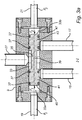
- the valve assembly 9 comprises a valve chamber 33 and a valve member, in the form of a cylindrical valve plunger 35, displaceably arranged in the valve chamber 33 and sealed with regard to a cylindrical wall of the valve chamber 33 by means of sealing rings 37.
- the valve chamber 33 comprises a first sub-chamber 33a to which the first detection conduit 19 is fluidly connected, and a second sub-chamber 33b to which the second detection conduit 21 is fluidly connected.
- the first and second valve sub-chambers 33a, 33b are separated from each other by the movable valve plunger 35.
- the cylindrical valve member 35 comprises a fluid passage portion 39 for distribution of fire extinguishing medium from the fire extinguishing medium container 3 to the first or to the second fire extinguishing sub-systems 5, 7.
- the fluid passage portion 39 is formed by a circumferential recess in the cylindrical valve member 35.
- the fluid passage portion may instead, or as a complement to a recess, comprise channels through the valve member.
- the valve member 35 further comprises a first blocking portion 41 arranged at one side of the fluid passage portion 39 and a second blocking portion 43 arranged at the other side of the fluid passage portion 39.
- Each of the first and second fire extinguishing sub-systems 5, 7 is fluidly connected the valve chamber 33 of the valve assembly 9.
- each of the first and second pipe systems 15, 17 is fluidly connected to the valve chamber 33 of the valve assembly 33, as illustrated in Fig. 2a .
- the valve member 35 comprises a first force receiving surface, in the form of a first pressure surface 45, arranged to be exposed to a first pressure force exerted by pressurized fluid in the first detection conduit 19, which is fluidly connected to the first valve chamber 33a, and for moving the valve member 35 in a direction away from the first detection conduit 19.
- the valve member 35 further comprises a second force receiving surface, in the form of a second pressure surface 47, arranged to be exposed to a second pressure force exerted by pressurized fluid in the second detection conduit 21, which is fluidly connected to the second valve chamber 33b, and for moving the valve member 35 in a direction away from the second detection conduit 21.
- a second force receiving surface in the form of a second pressure surface 47, arranged to be exposed to a second pressure force exerted by pressurized fluid in the second detection conduit 21, which is fluidly connected to the second valve chamber 33b, and for moving the valve member 35 in a direction away from the second detection conduit 21.
- the valve assembly 9 comprises a common detection fluid channel 49.
- the common detection fluid channel 49 branches into a first sub-channel 51 fluidly connecting the detection fluid container 23 to the first valve chamber 33a, and into a second sub-channel 55 fluidly connecting the detection fluid container 23 to the second sub-chamber 33b.
- the first sub-channel 51 comprises a first valve seat 55 against which a first ball 57 is seated.
- the first ball 57 is pressed against the first valve seat 55 by means of a first spring 59 supported by an inner wall of the first sub-channel 51.
- the first valve seat 55, the first ball 57 and the first spring 59 form part of a first check valve preventing fluid flow from the first detection conduit 19 to the common channel 49.
- the second sub-channel 53 comprises a second valve seat 61 against which a second ball 63 is seated.
- the second ball 63 is pressed against the second valve seat 61 by means of a second spring 65.
- the second valve seat 61, the second ball 63 and the second spring 65 form part of a second check valve preventing detection fluid from flowing from the second detection conduit 21 to the common channel 49.
- Fig. 3a shows a state in which each of the first and second detection conduct 19, 21 is intact and filled with pressurized detection liquid.
- the pressure of the detection liquid in the first and second detection conduits 19, 21 is then P 1 and P 2 , respectively.
- a first pressure force F 1 is exerted on the first pressure surface 45 of the valve member 35 and a second pressure force F 2 is exerted on the second pressure surface 47 of the valve member 35.
- the pressurized liquid in the first detection conduit 19 forms a first force applicator and the pressurized liquid in the second detection conduit 21 forms a second force applicator.
- Fig. 3b illustrates fire in the second compartment 8, i.e. where the second detection conduit 21 and the second fire extinguishing sub-system 7 are arranged.
- the second detection conduit 21 bursts due to heat generated by the fire. Consequently, detection liquid leaks from the detection conduit 21, as illustrated by arrow A in Fig. 3b .
- the pressure in the second valve chamber 33b drops and the second pressure force F 2 is removed.
- the first check valve prevents fluid from being evacuated from the first detection conduit 19. Hence, the first pressure force F 1 is maintained since the first valve chamber 33a is still pressurized.
- the valve member 35 is then moved to a first position, illustrated in Fig.
- valve member 35 by the pressure force F 1 exerted on the first pressure surface 45 of the valve member 35 by pressurized detection liquid in the first valve chamber 33a, i.e. by the first force applicator, as illustrated by the arrow B in Fig. 3b .
- the valve member 35 is moved to the first position upon a pressure difference between the first and second valve chambers 33a, 33b of approximately 2-5 bar.
- the fluid passage portion 39 is positioned for distribution of fire extinguishing medium from the fire extinguishing medium container 3 to the tube 17 of the second extinguishing sub-system 7.
- the pressure in each of the detection tube 24 and connection tube 28, which are fluidly connected to the second detection conduit 21, drops upon leakage of detection fluid from the second detection conduit 21.
- the release valve 25 on the fire extinguishing medium container 3 is activated.
- extinguishing fluid is supplied to the second fire extinguishing sub-system 7, as illustrated by the arrow C in Fig. 3b .
- the first valve member position distribution of fire extinguishing medium to the first fire extinguishing sub-system 5 is prevented by the first blocking portion 41 of the valve member 35. Fire extinguishing medium is thus supplied only to the second sub-system 7 when the valve member 35 assumes the first valve member position.
- Fig. 3c illustrates fire in the first compartment 6, i.e. where the first detection conduit 19 and the first fire extinguishing sub-system 5 are arranged.
- the first detection conduit 19 bursts due to heat generated by the fire. Consequently, detection liquid leaks from the first detection conduit 19, as illustrated by arrow D in Fig. 3c .
- the pressure in the first valve chamber 33a drops and the first pressure force F 1 is removed.
- the second check valve prevents fluid from being evacuated from the second detection conduit 21.
- the second pressure force F 2 is maintained since the second valve chamber 33b is still pressurized.
- the valve member 35 is then moved to a second position, illustrated in Fig.
- valve member 35 by the pressure force F 2 exerted on the second pressure surface 47 of the valve member 35 by pressurized detection liquid in the second valve chamber 33b, i.e. by the second force applicator, as illustrated by the arrow E in Fig. 3c .
- the valve member 35 is moved to the second position upon a pressure difference between the first and second valve chambers 33a, 33b of approximately 2-5 bar.
- the fluid passage portion 39 is positioned for distribution of fire extinguishing medium from the fire extinguishing container 3 to the tube 15 of the first extinguishing sub-system 5.
- the pressure in each of the detection tube 24 and the connection tube 28, which are fluidly connected to the first detection conduit 19, drops upon leakage of detection fluid from the first detection conduit 19.
- the release valve 25 on the fire extinguishing medium container 3 is activated.
- extinguishing fluid is supplied to the first fire extinguishing sub-system 5, as illustrated by the arrow F in Fig. 3c .
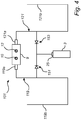
- the second example differs from the first embodiment in that it comprises electrical detection conduits instead of pressurized detection conduits.
- the fire extinguishing system 101 thus comprises a first and a second electrical detection conduit arrangement 119, 121.
- the fire extinguishing system 101 further comprises a container 3 for fire extinguishing medium, a first fire extinguishing sub-system (not shown), a second fire extinguishing sub-system (not shown), a valve assembly 9, which is fluidly connected to the fire extinguishing medium container 3 by a tube (not shown), for distribution of fire extinguishing medium to the first or to the second fire extinguishing sub-system and a release valve 25 arranged to open supply of fire extinguishing medium from the fire extinguishing medium container 3 to the valve assembly 9.
- the second fire extinguishing sub-system which is arranged in the compartment where the second detection conduit arrangement 121 is arranged, is fluidly connected to the valve chamber 33 via a first valve port 10 of the valve assembly 9 and the first fire extinguishing sub-system, which is arranged in the compartment where the first detection conduit arrangement 121 is arranged, is fluidly connected to the valve chamber 33 via a second valve port 12 of the valve assembly 9 while in the first embodiment the first fire extinguishing sub-system is fluidly connected to the valve chamber 33 via the first valve port 10 and the second fire extinguishing sub-system is fluidly connected to the valve chamber 33 via the second valve port 12.
- the reason for the crosswise connection of the fire extinguishing sub-systems in the second example is that, upon detection of fire in e.g. the first compartment, the piston member 35 is moved in the opposite direction compared to the corresponding piston movement in the first embodiment.
- the first detection conduit arrangement 119 comprises a first force applicator, in the form of a pyrotechnical actuator 119a, and an energized electrical detection cable 119b.
- the second detection conduit arrangement 121 comprises a second force applicator, in the form of a pyrotechnical actuator 121a, and an energized electrical detection cable 121b.
- Each of the first and second detection cables 119b, 121b comprises two adjacent conductors and a meltable insulating layer therebetween. In the event of fire the insulating layer melts due to heat generated by the fire. Then, an electrical impulse is generated in the detection cable.
- the first detection cable 119b is connected to each of the pyrotechnical actuator 119a and the release valve 25 and arranged to activate each of the pyrotechnical actuator 119a and the release valve 25 in case of fire in the compartment where the first detection conduit arrangement 119 is installed. In the event of fire in the compartment where the first detection conduit arrangement is arranged each of the first pyrotechnical actuator 119a and the release valve 25 thus receives an electrical impulse from the detection cable 119b.
- the second detection cable 121b is connected to each of the second pyrotechnical actuator 121a and the release valve 25 and arranged to activate each of the second pyrotechnical actuator 121a and the release valve 25 in case of fire in the compartment where the second detection conduit arrangement 121 is arranged. In the event of fire in the compartment where the second detection conduit arrangement 121 is arranged each of the second pyrotechnical actuator 121a and the release valve 25 thus receives an electrical impulse from the second detection cable 121b.
- the release valve 25 may e.g. be activated in a known manner by means of a pyrotechnical charge arranged to be ignited by an electrical impulse from any of the first and second electrical detection cable 119b, 121b.
- a first diode 151 is arranged to secure that only the second pyrotechnical actuator 121a is activated when an electrical impulse is generated by the second detection cable 121b.
- a second diode 153 is arranged to secure that only the first pyrotechnical actuator 119a is activated when an electrical impulse is generated by the first detection cable 119b.
- the pyrotechnical actuator 121a of the second detection conduit arrangement 121 comprises a pyrotechnical charge 121c which is arranged to be initiated by an electrical impulse from the second detection cable 121b.
- pressurized gas is generated and forwarded into the second valve chamber 33b, as illustrated by arrow G in Fig. 5b .
- the pressurized gas exerts a pressure force on the force receiving surface 47 of the valve member 35.
- valve member 35 is moved to a valve member position, in which the fluid passage portion 39 of the valve member 35 is aligned for distribution of fire extinguishing medium to the second fire extinguishing sub-system, by the force applied by pressurized gas in the second valve chamber 33b, as illustrated by the arrow H in Fig. 5b .
- each of the first and second force applicator comprises a piston.
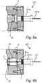
- Fig. 6a shows a part of the second detection conduit arrangement 221.
- the second detection conduit arrangement 221 comprises a force applicator, in the form of a pyrotechnical piston actuator 221a, and an energized electrical detection cable 221b.
- the pyrotechnical piston actuator 221a comprises a pyrotechnical charge (not shown), which is arranged to be initiated by an electrical impulse from the second detection cable 221b, and a piston 221c, illustrated in Fig. 6b .
- Upon initiation of the pyrotechnical charge the piston is moved towards the valve member 35, as illustrated by arrow I in Fig. 6b .
- valve member 35 As soon as the piston 221c contacts the valve member 35 a force is exerted on the force receiving surface 47 of the valve member 35. Then, the valve member 35 is moved to a valve member position, in which the fluid passage portion 39 of the valve member 35 is aligned for distribution of fire extinguishing medium to the second fire extinguishing sub-system, by the force exerted by the piston 221c of the pyrotechnical piston actuator 221a, as illustrated by the arrow J in Fig. 6b .
- the fire extinguishing medium may be a fluid in the form of a liquid. It is appreciated that the fire extinguishing medium may be a fluid in the form of a gas, such as, e.g., Carbon dioxide, Nitrogen, Argon or compressed air.
- a gas such as, e.g., Carbon dioxide, Nitrogen, Argon or compressed air.
- detection fluid in the form of detection liquid may be used. It is however realised that detection fluid in the form of detection gas, such as e.g. nitrogen, may be used instead of detection liquid.
- detection conduit is preferably gas-tight.
- a gas-tight detection hose formed from polyamide may be used.
Landscapes
- Health & Medical Sciences (AREA)
- Public Health (AREA)
- Business, Economics & Management (AREA)
- Emergency Management (AREA)
- Engineering & Computer Science (AREA)
- General Engineering & Computer Science (AREA)
- Mechanical Engineering (AREA)
- Fire-Extinguishing By Fire Departments, And Fire-Extinguishing Equipment And Control Thereof (AREA)
Claims (9)
- Feuerlöschsystem, umfassend:einen Feuerlöschmediumbehälter (3),ein erstes (5) und ein zweites (7) Feuerlöschuntersystem undeine Ventilanordnung (9), die den Feuerlöschmediumbehälter (3) mit jedem des ersten (5) und zweiten (7) Feuerlöschuntersystems fluidverbindet und die zum selektiven Verteilen eines Feuerlöschmediums von dem Feuerlöschmediumbehälter (3) auf das erste (5) oder auf das zweite (7) Feuerlöschuntersystem bei Aktivierung des Feuerlöschsystems (1) angeordnet ist,dadurch gekennzeichnet, dassdas Feuerlöschsystem (1) ferner eine erste und eine zweite Erfassungsleitungsanordnung (19, 21; 119, 121) umfasst, die mit der Ventilanordnung (9) verbunden ist und die dazu konfiguriert ist, das Feuerlöschsystem zu aktivieren, wobei die Ventilanordnung (9) eine Ventilkammer (33), ein Ventilelement (35), das in der Ventilkammer (33) bewegbar angeordnet ist, und einen Fluiddurchgangsabschnitt (39), der in mindestens einem von dem Ventilelement (35) und der Ventilkammer (33) angeordnet ist, umfasst,wobei das Ventilelement (35) Folgendes aufweist:i) eine erste Kraftaufnahmefläche (45), die angeordnet ist, um bei Aktivierung einer ersten Kraft (F1) ausgesetzt zu werden, die durch eine Kraftaufbringeinrichtung (19, 119a) ausgeübt wird, die ein mit Druck beaufschlagtes Fluid ist, der ersten Erfassungsleitungsanordnung (19; 119) und zum Bewegen des Ventilelements (35) zu einer ersten Position, in der der Fluiddurchgangsabschnitt (39) zur Verteilung eines Feuerlöschmediums auf das zweite Feuerlöschuntersystem (7) ausgerichtet ist, undii) eine zweite Kraftaufnahmefläche (47), die angeordnet ist, um bei Aktivierung einer zweiten Kraft (F2) ausgesetzt zu werden, die durch eine Kraftaufbringeinrichtung (21; 121a) ausgeübt wird, die ein mit Druck beaufschlagtes Fluid ist, der zweiten Erfassungsleitungsanordnung (21; 121) und zum Bewegen des Ventilelements (35) zu einer zweiten Position, in der der Fluiddurchgangsabschnitt (39) zur Verteilung eines Feuerlöschmediums auf das erste Feuerlöschuntersystem (5) ausgerichtet ist.
- Feuerlöschsystem nach Anspruch 1, wobei das Ventilelement (35) angeordnet ist, um sich entlang eines linearen Pfads entlang der Ventilkammer (33) zu bewegen.
- Feuerlöschsystem nach Anspruch 2, wobei die erste (45) und zweite (47) Kraftaufnahmefläche einander gegenüberliegen.
- Feuerlöschsystem nach einem der vorhergehenden Ansprüche, wobei das Ventilelement (35) ein Ventilstößel ist.
- Feuerlöschsystem nach einem der vorhergehenden Ansprüche, wobei der Ventilstößel zylindrisch ist.
- Feuerlöschsystem nach einem der vorhergehenden Ansprüche, wobei der Fluiddurchgangsabschnitt (39) in dem Ventilelement (35) angeordnet ist.
- Feuerlöschsystem nach einem der vorhergehenden Ansprüche, wobei das Ventilelement (35) mindestens einen ersten Sperrabschnitt (41) umfasst, der angeordnet ist, um eine Verteilung eines Feuerlöschmediums auf das erste (5) oder auf das zweite (7) Feuerlöschuntersystem zu verhindern.
- Feuerlöschsystem nach einem der vorhergehenden Ansprüche, wobei mindestens eine der ersten und zweiten Erfassungsleitungsanordnung (19, 21; 119, 121) eine mit Flüssigkeit gefüllte Erfassungsleitung umfasst.
- Feuerlöschsystem nach einem der vorhergehenden Ansprüche, wobei mindestens eine der ersten und zweiten Erfassungsleitungsanordnung (19, 21; 119, 121) eine Erfassungsleitung umfasst, die aus einem thermoplastischen Material, wie etwa einem thermoplastischen Fluorpolymer, gebildet ist.
Priority Applications (5)
| Application Number | Priority Date | Filing Date | Title |
|---|---|---|---|
| EP14174657.8A EP2959946B1 (de) | 2014-06-27 | 2014-06-27 | Feuerlöschsystem |
| US15/321,236 US10668310B2 (en) | 2014-06-27 | 2015-06-25 | Fire extinguishing system |
| CA2953417A CA2953417C (en) | 2014-06-27 | 2015-06-25 | Fire extinguishing system |
| AU2015279205A AU2015279205B2 (en) | 2014-06-27 | 2015-06-25 | Fire extinguishing system |
| PCT/EP2015/064357 WO2015197756A1 (en) | 2014-06-27 | 2015-06-25 | Fire extinguishing system |
Applications Claiming Priority (1)
| Application Number | Priority Date | Filing Date | Title |
|---|---|---|---|
| EP14174657.8A EP2959946B1 (de) | 2014-06-27 | 2014-06-27 | Feuerlöschsystem |
Publications (2)
| Publication Number | Publication Date |
|---|---|
| EP2959946A1 EP2959946A1 (de) | 2015-12-30 |
| EP2959946B1 true EP2959946B1 (de) | 2019-04-24 |
Family
ID=51133850
Family Applications (1)
| Application Number | Title | Priority Date | Filing Date |
|---|---|---|---|
| EP14174657.8A Active EP2959946B1 (de) | 2014-06-27 | 2014-06-27 | Feuerlöschsystem |
Country Status (5)
| Country | Link |
|---|---|
| US (1) | US10668310B2 (de) |
| EP (1) | EP2959946B1 (de) |
| AU (1) | AU2015279205B2 (de) |
| CA (1) | CA2953417C (de) |
| WO (1) | WO2015197756A1 (de) |
Families Citing this family (12)
| Publication number | Priority date | Publication date | Assignee | Title |
|---|---|---|---|---|
| US9982511B2 (en) | 2014-01-03 | 2018-05-29 | Proserv Operations, Inc. | Dirty fluid pressure regulator and control valve |
| US10670155B2 (en) | 2015-10-05 | 2020-06-02 | Proserv Gilmore Valve Llc | Latching poppet valve |
| US10487951B2 (en) * | 2016-01-22 | 2019-11-26 | Proserv Operations, Inc. | Non-interflow directional control valve |
| CN105582635B (zh) * | 2016-03-22 | 2018-10-02 | 北京利达海鑫灭火系统设备有限公司 | 探火管感温自启动灭火装置选择阀 |
| US10591076B2 (en) | 2016-09-15 | 2020-03-17 | Proserv Operations, Inc. | Low friction hydraulic circuit control components |
| US10739796B2 (en) | 2017-09-22 | 2020-08-11 | Proserv Gilmore Valve Llc | Pressure regulator with reconfigurable hydraulic dampening |
| US10633951B2 (en) | 2017-09-22 | 2020-04-28 | Proserv Operations, Inc. | Pressure regulator with user selectable dampening |
| US11022226B2 (en) | 2018-03-20 | 2021-06-01 | Proserv Operations, Inc. | Microfluidic valve |
| US11054050B2 (en) | 2018-08-13 | 2021-07-06 | Proserv Operations Inc. | Valve with press-fit insert |
| US11209096B2 (en) | 2018-11-19 | 2021-12-28 | Proserv Operations, Inc. | Bilateral and throttling directional control valve |
| US11261982B2 (en) | 2019-06-27 | 2022-03-01 | Proserv Gilmore Valve Llc | Pressure relief valve with bi-directional seat |
| US11828370B2 (en) | 2020-01-02 | 2023-11-28 | Proserv Gilmore Valve Llc | Check valve with conforming seat |
Family Cites Families (10)
| Publication number | Priority date | Publication date | Assignee | Title |
|---|---|---|---|---|
| US3122350A (en) * | 1960-10-26 | 1964-02-25 | Ansul Chemical Co | Quick opening valve |
| GB9026894D0 (en) * | 1990-12-11 | 1991-01-30 | Melton David L | Damage sensing apparatus |
| US6209654B1 (en) * | 2000-07-19 | 2001-04-03 | Mac Curless | Deluge fire sprinkler system |
| AR062764A1 (es) * | 2006-11-06 | 2008-12-03 | Victaulic Co Of America | Metodo y aparato para secar redes de canerias equipadas con rociadores |
| CA2693414C (en) * | 2007-07-13 | 2015-12-29 | William A. Eckholm | Methods and apparatus for hazard control |
| CN102089040B (zh) * | 2008-04-10 | 2012-11-28 | Utc消防及保安公司 | 具有经过改进的两相流分布的火灾扑救系统 |
| GB2474271B (en) * | 2009-10-08 | 2014-04-02 | Kidde Tech Inc | Fire suppression system |
| GB2486267B (en) * | 2010-12-09 | 2014-12-17 | Kidde Tech Inc | Combined fire extinguishing system |
| WO2012145733A1 (en) * | 2011-04-22 | 2012-10-26 | Vanderbilt University | Para-hydrogen polarizer |
| US8757191B2 (en) * | 2011-12-08 | 2014-06-24 | Kiddie Technologies, Inc. | High rate discharge (HRD) valve opening mechanism for a fire and explosion protection |
-
2014
- 2014-06-27 EP EP14174657.8A patent/EP2959946B1/de active Active
-
2015
- 2015-06-25 AU AU2015279205A patent/AU2015279205B2/en active Active
- 2015-06-25 WO PCT/EP2015/064357 patent/WO2015197756A1/en active Application Filing
- 2015-06-25 US US15/321,236 patent/US10668310B2/en active Active
- 2015-06-25 CA CA2953417A patent/CA2953417C/en active Active
Non-Patent Citations (1)
| Title |
|---|
| None * |
Also Published As
| Publication number | Publication date |
|---|---|
| CA2953417A1 (en) | 2015-12-30 |
| AU2015279205B2 (en) | 2019-09-19 |
| US20170189730A1 (en) | 2017-07-06 |
| US10668310B2 (en) | 2020-06-02 |
| WO2015197756A1 (en) | 2015-12-30 |
| EP2959946A1 (de) | 2015-12-30 |
| AU2015279205A1 (en) | 2017-02-02 |
| CA2953417C (en) | 2022-02-22 |
Similar Documents
| Publication | Publication Date | Title |
|---|---|---|
| EP2959946B1 (de) | Feuerlöschsystem | |
| KR101157245B1 (ko) | 가스 연료 차량 및 자동 배출 시스템 | |
| US8646540B2 (en) | Methods and apparatus for passive non-electrical dual stage fire suppression | |
| KR101938885B1 (ko) | 미분무수 소화 시스템용 열팽창 조립체 | |
| US9072925B2 (en) | Valve | |
| US10942533B2 (en) | System for multiple pressure relief device activation | |
| EP3062893B1 (de) | Feuerlöschsystem | |
| CN105611972A (zh) | 自动灭火装置及使用于该自动灭火装置的火灾探测管 | |
| JP2023529224A (ja) | 熱作動式圧力逃し装置(tprd)、ガス圧力タンク、およびtprdを含むガス圧力タンクシステム、ならびに熱過剰圧力保護のための方法 | |
| US10197176B2 (en) | Thermally-controlled fluid supply assembly | |
| US9974991B2 (en) | Fire detection system | |
| AU2014343680A1 (en) | Fire extinguishing system | |
| KR101355831B1 (ko) | 소방용 소화장치 | |
| KR101373131B1 (ko) | 엔진룸 화재 자동 소화장치 | |
| DK2781818T3 (en) | Coupling to the cryogenic liquid media | |
| US20160215894A1 (en) | Pressure-balanced valve | |
| EP3638605B1 (de) | Queraktivierte druckentlastungsvorrichtung | |
| US11590373B2 (en) | Fire extinguishing system for vehicle | |
| US8931502B2 (en) | Gas-dispensing device and facility comprising such a device | |
| EP2905053A1 (de) | Düsenanordnung | |
| KR20030094321A (ko) | 폐쇄된 액체시스템에 액체를 공급하는 방법 | |
| AU2011280137B2 (en) | Methods and apparatus for passive non-electrical dual stage fire suppresion | |
| SE542080C2 (en) | A supply device for a valve arrangement, a valve arrangement, a gas reservoir and a vehicle |
Legal Events
| Date | Code | Title | Description |
|---|---|---|---|
| PUAI | Public reference made under article 153(3) epc to a published international application that has entered the european phase |
Free format text: ORIGINAL CODE: 0009012 |
|
| AK | Designated contracting states |
Kind code of ref document: A1 Designated state(s): AL AT BE BG CH CY CZ DE DK EE ES FI FR GB GR HR HU IE IS IT LI LT LU LV MC MK MT NL NO PL PT RO RS SE SI SK SM TR |
|
| AX | Request for extension of the european patent |
Extension state: BA ME |
|
| 17P | Request for examination filed |
Effective date: 20160630 |
|
| RBV | Designated contracting states (corrected) |
Designated state(s): AL AT BE BG CH CY CZ DE DK EE ES FI FR GB GR HR HU IE IS IT LI LT LU LV MC MK MT NL NO PL PT RO RS SE SI SK SM TR |
|
| GRAP | Despatch of communication of intention to grant a patent |
Free format text: ORIGINAL CODE: EPIDOSNIGR1 |
|
| STAA | Information on the status of an ep patent application or granted ep patent |
Free format text: STATUS: GRANT OF PATENT IS INTENDED |
|
| INTG | Intention to grant announced |
Effective date: 20181126 |
|
| GRAS | Grant fee paid |
Free format text: ORIGINAL CODE: EPIDOSNIGR3 |
|
| GRAA | (expected) grant |
Free format text: ORIGINAL CODE: 0009210 |
|
| STAA | Information on the status of an ep patent application or granted ep patent |
Free format text: STATUS: THE PATENT HAS BEEN GRANTED |
|
| AK | Designated contracting states |
Kind code of ref document: B1 Designated state(s): AL AT BE BG CH CY CZ DE DK EE ES FI FR GB GR HR HU IE IS IT LI LT LU LV MC MK MT NL NO PL PT RO RS SE SI SK SM TR |
|
| REG | Reference to a national code |
Ref country code: GB Ref legal event code: FG4D |
|
| REG | Reference to a national code |
Ref country code: CH Ref legal event code: EP |
|
| REG | Reference to a national code |
Ref country code: DE Ref legal event code: R096 Ref document number: 602014045208 Country of ref document: DE |
|
| REG | Reference to a national code |
Ref country code: AT Ref legal event code: REF Ref document number: 1123431 Country of ref document: AT Kind code of ref document: T Effective date: 20190515 Ref country code: IE Ref legal event code: FG4D |
|
| REG | Reference to a national code |
Ref country code: SE Ref legal event code: TRGR |
|
| REG | Reference to a national code |
Ref country code: NL Ref legal event code: MP Effective date: 20190424 |
|
| REG | Reference to a national code |
Ref country code: LT Ref legal event code: MG4D |
|
| PG25 | Lapsed in a contracting state [announced via postgrant information from national office to epo] |
Ref country code: NL Free format text: LAPSE BECAUSE OF FAILURE TO SUBMIT A TRANSLATION OF THE DESCRIPTION OR TO PAY THE FEE WITHIN THE PRESCRIBED TIME-LIMIT Effective date: 20190424 |
|
| PG25 | Lapsed in a contracting state [announced via postgrant information from national office to epo] |
Ref country code: FI Free format text: LAPSE BECAUSE OF FAILURE TO SUBMIT A TRANSLATION OF THE DESCRIPTION OR TO PAY THE FEE WITHIN THE PRESCRIBED TIME-LIMIT Effective date: 20190424 Ref country code: NO Free format text: LAPSE BECAUSE OF FAILURE TO SUBMIT A TRANSLATION OF THE DESCRIPTION OR TO PAY THE FEE WITHIN THE PRESCRIBED TIME-LIMIT Effective date: 20190724 Ref country code: LT Free format text: LAPSE BECAUSE OF FAILURE TO SUBMIT A TRANSLATION OF THE DESCRIPTION OR TO PAY THE FEE WITHIN THE PRESCRIBED TIME-LIMIT Effective date: 20190424 Ref country code: HR Free format text: LAPSE BECAUSE OF FAILURE TO SUBMIT A TRANSLATION OF THE DESCRIPTION OR TO PAY THE FEE WITHIN THE PRESCRIBED TIME-LIMIT Effective date: 20190424 Ref country code: ES Free format text: LAPSE BECAUSE OF FAILURE TO SUBMIT A TRANSLATION OF THE DESCRIPTION OR TO PAY THE FEE WITHIN THE PRESCRIBED TIME-LIMIT Effective date: 20190424 Ref country code: AL Free format text: LAPSE BECAUSE OF FAILURE TO SUBMIT A TRANSLATION OF THE DESCRIPTION OR TO PAY THE FEE WITHIN THE PRESCRIBED TIME-LIMIT Effective date: 20190424 Ref country code: PT Free format text: LAPSE BECAUSE OF FAILURE TO SUBMIT A TRANSLATION OF THE DESCRIPTION OR TO PAY THE FEE WITHIN THE PRESCRIBED TIME-LIMIT Effective date: 20190824 |
|
| PG25 | Lapsed in a contracting state [announced via postgrant information from national office to epo] |
Ref country code: BG Free format text: LAPSE BECAUSE OF FAILURE TO SUBMIT A TRANSLATION OF THE DESCRIPTION OR TO PAY THE FEE WITHIN THE PRESCRIBED TIME-LIMIT Effective date: 20190724 Ref country code: LV Free format text: LAPSE BECAUSE OF FAILURE TO SUBMIT A TRANSLATION OF THE DESCRIPTION OR TO PAY THE FEE WITHIN THE PRESCRIBED TIME-LIMIT Effective date: 20190424 Ref country code: RS Free format text: LAPSE BECAUSE OF FAILURE TO SUBMIT A TRANSLATION OF THE DESCRIPTION OR TO PAY THE FEE WITHIN THE PRESCRIBED TIME-LIMIT Effective date: 20190424 Ref country code: PL Free format text: LAPSE BECAUSE OF FAILURE TO SUBMIT A TRANSLATION OF THE DESCRIPTION OR TO PAY THE FEE WITHIN THE PRESCRIBED TIME-LIMIT Effective date: 20190424 Ref country code: GR Free format text: LAPSE BECAUSE OF FAILURE TO SUBMIT A TRANSLATION OF THE DESCRIPTION OR TO PAY THE FEE WITHIN THE PRESCRIBED TIME-LIMIT Effective date: 20190725 |
|
| REG | Reference to a national code |
Ref country code: AT Ref legal event code: MK05 Ref document number: 1123431 Country of ref document: AT Kind code of ref document: T Effective date: 20190424 |
|
| PG25 | Lapsed in a contracting state [announced via postgrant information from national office to epo] |
Ref country code: IS Free format text: LAPSE BECAUSE OF FAILURE TO SUBMIT A TRANSLATION OF THE DESCRIPTION OR TO PAY THE FEE WITHIN THE PRESCRIBED TIME-LIMIT Effective date: 20190824 |
|
| REG | Reference to a national code |
Ref country code: DE Ref legal event code: R097 Ref document number: 602014045208 Country of ref document: DE |
|
| PG25 | Lapsed in a contracting state [announced via postgrant information from national office to epo] |
Ref country code: SK Free format text: LAPSE BECAUSE OF FAILURE TO SUBMIT A TRANSLATION OF THE DESCRIPTION OR TO PAY THE FEE WITHIN THE PRESCRIBED TIME-LIMIT Effective date: 20190424 Ref country code: MC Free format text: LAPSE BECAUSE OF FAILURE TO SUBMIT A TRANSLATION OF THE DESCRIPTION OR TO PAY THE FEE WITHIN THE PRESCRIBED TIME-LIMIT Effective date: 20190424 Ref country code: DK Free format text: LAPSE BECAUSE OF FAILURE TO SUBMIT A TRANSLATION OF THE DESCRIPTION OR TO PAY THE FEE WITHIN THE PRESCRIBED TIME-LIMIT Effective date: 20190424 Ref country code: AT Free format text: LAPSE BECAUSE OF FAILURE TO SUBMIT A TRANSLATION OF THE DESCRIPTION OR TO PAY THE FEE WITHIN THE PRESCRIBED TIME-LIMIT Effective date: 20190424 Ref country code: EE Free format text: LAPSE BECAUSE OF FAILURE TO SUBMIT A TRANSLATION OF THE DESCRIPTION OR TO PAY THE FEE WITHIN THE PRESCRIBED TIME-LIMIT Effective date: 20190424 Ref country code: CZ Free format text: LAPSE BECAUSE OF FAILURE TO SUBMIT A TRANSLATION OF THE DESCRIPTION OR TO PAY THE FEE WITHIN THE PRESCRIBED TIME-LIMIT Effective date: 20190424 Ref country code: RO Free format text: LAPSE BECAUSE OF FAILURE TO SUBMIT A TRANSLATION OF THE DESCRIPTION OR TO PAY THE FEE WITHIN THE PRESCRIBED TIME-LIMIT Effective date: 20190424 |
|
| REG | Reference to a national code |
Ref country code: CH Ref legal event code: PL |
|
| PG25 | Lapsed in a contracting state [announced via postgrant information from national office to epo] |
Ref country code: IT Free format text: LAPSE BECAUSE OF FAILURE TO SUBMIT A TRANSLATION OF THE DESCRIPTION OR TO PAY THE FEE WITHIN THE PRESCRIBED TIME-LIMIT Effective date: 20190424 Ref country code: SM Free format text: LAPSE BECAUSE OF FAILURE TO SUBMIT A TRANSLATION OF THE DESCRIPTION OR TO PAY THE FEE WITHIN THE PRESCRIBED TIME-LIMIT Effective date: 20190424 |
|
| PLBE | No opposition filed within time limit |
Free format text: ORIGINAL CODE: 0009261 |
|
| STAA | Information on the status of an ep patent application or granted ep patent |
Free format text: STATUS: NO OPPOSITION FILED WITHIN TIME LIMIT |
|
| REG | Reference to a national code |
Ref country code: BE Ref legal event code: MM Effective date: 20190630 |
|
| PG25 | Lapsed in a contracting state [announced via postgrant information from national office to epo] |
Ref country code: TR Free format text: LAPSE BECAUSE OF FAILURE TO SUBMIT A TRANSLATION OF THE DESCRIPTION OR TO PAY THE FEE WITHIN THE PRESCRIBED TIME-LIMIT Effective date: 20190424 |
|
| 26N | No opposition filed |
Effective date: 20200127 |
|
| PG25 | Lapsed in a contracting state [announced via postgrant information from national office to epo] |
Ref country code: IE Free format text: LAPSE BECAUSE OF NON-PAYMENT OF DUE FEES Effective date: 20190627 |
|
| PG25 | Lapsed in a contracting state [announced via postgrant information from national office to epo] |
Ref country code: LI Free format text: LAPSE BECAUSE OF NON-PAYMENT OF DUE FEES Effective date: 20190630 Ref country code: LU Free format text: LAPSE BECAUSE OF NON-PAYMENT OF DUE FEES Effective date: 20190627 Ref country code: SI Free format text: LAPSE BECAUSE OF FAILURE TO SUBMIT A TRANSLATION OF THE DESCRIPTION OR TO PAY THE FEE WITHIN THE PRESCRIBED TIME-LIMIT Effective date: 20190424 Ref country code: BE Free format text: LAPSE BECAUSE OF NON-PAYMENT OF DUE FEES Effective date: 20190630 Ref country code: CH Free format text: LAPSE BECAUSE OF NON-PAYMENT OF DUE FEES Effective date: 20190630 |
|
| PG25 | Lapsed in a contracting state [announced via postgrant information from national office to epo] |
Ref country code: CY Free format text: LAPSE BECAUSE OF FAILURE TO SUBMIT A TRANSLATION OF THE DESCRIPTION OR TO PAY THE FEE WITHIN THE PRESCRIBED TIME-LIMIT Effective date: 20190424 |
|
| PG25 | Lapsed in a contracting state [announced via postgrant information from national office to epo] |
Ref country code: MT Free format text: LAPSE BECAUSE OF FAILURE TO SUBMIT A TRANSLATION OF THE DESCRIPTION OR TO PAY THE FEE WITHIN THE PRESCRIBED TIME-LIMIT Effective date: 20190424 Ref country code: HU Free format text: LAPSE BECAUSE OF FAILURE TO SUBMIT A TRANSLATION OF THE DESCRIPTION OR TO PAY THE FEE WITHIN THE PRESCRIBED TIME-LIMIT; INVALID AB INITIO Effective date: 20140627 |
|
| PG25 | Lapsed in a contracting state [announced via postgrant information from national office to epo] |
Ref country code: MK Free format text: LAPSE BECAUSE OF FAILURE TO SUBMIT A TRANSLATION OF THE DESCRIPTION OR TO PAY THE FEE WITHIN THE PRESCRIBED TIME-LIMIT Effective date: 20190424 |
|
| PGFP | Annual fee paid to national office [announced via postgrant information from national office to epo] |
Ref country code: FR Payment date: 20230515 Year of fee payment: 10 Ref country code: DE Payment date: 20230517 Year of fee payment: 10 |
|
| PGFP | Annual fee paid to national office [announced via postgrant information from national office to epo] |
Ref country code: SE Payment date: 20230516 Year of fee payment: 10 |
|
| PGFP | Annual fee paid to national office [announced via postgrant information from national office to epo] |
Ref country code: GB Payment date: 20230515 Year of fee payment: 10 |