EP4085203B1 - Elektrische maschine, die mit einer lösbaren lageranordnung versehen ist - Google Patents
Elektrische maschine, die mit einer lösbaren lageranordnung versehen ist Download PDFInfo
- Publication number
- EP4085203B1 EP4085203B1 EP20841744.4A EP20841744A EP4085203B1 EP 4085203 B1 EP4085203 B1 EP 4085203B1 EP 20841744 A EP20841744 A EP 20841744A EP 4085203 B1 EP4085203 B1 EP 4085203B1
- Authority
- EP
- European Patent Office
- Prior art keywords
- bearing
- electric machine
- rotor
- holes
- labyrinth seal
- Prior art date
- Legal status (The legal status is an assumption and is not a legal conclusion. Google has not performed a legal analysis and makes no representation as to the accuracy of the status listed.)
- Active
Links
Images


Classifications
-
- F—MECHANICAL ENGINEERING; LIGHTING; HEATING; WEAPONS; BLASTING
- F16—ENGINEERING ELEMENTS AND UNITS; GENERAL MEASURES FOR PRODUCING AND MAINTAINING EFFECTIVE FUNCTIONING OF MACHINES OR INSTALLATIONS; THERMAL INSULATION IN GENERAL
- F16C—SHAFTS; FLEXIBLE SHAFTS; ELEMENTS OR CRANKSHAFT MECHANISMS; ROTARY BODIES OTHER THAN GEARING ELEMENTS; BEARINGS
- F16C33/00—Parts of bearings; Special methods for making bearings or parts thereof
- F16C33/72—Sealings
- F16C33/76—Sealings of ball or roller bearings
- F16C33/80—Labyrinth sealings
- F16C33/805—Labyrinth sealings in addition to other sealings, e.g. dirt guards to protect sealings with sealing lips
-
- F—MECHANICAL ENGINEERING; LIGHTING; HEATING; WEAPONS; BLASTING
- F16—ENGINEERING ELEMENTS AND UNITS; GENERAL MEASURES FOR PRODUCING AND MAINTAINING EFFECTIVE FUNCTIONING OF MACHINES OR INSTALLATIONS; THERMAL INSULATION IN GENERAL
- F16C—SHAFTS; FLEXIBLE SHAFTS; ELEMENTS OR CRANKSHAFT MECHANISMS; ROTARY BODIES OTHER THAN GEARING ELEMENTS; BEARINGS
- F16C35/00—Rigid support of bearing units; Housings, e.g. caps, covers
- F16C35/04—Rigid support of bearing units; Housings, e.g. caps, covers in the case of ball or roller bearings
- F16C35/042—Housings for rolling element bearings for rotary movement
-
- F—MECHANICAL ENGINEERING; LIGHTING; HEATING; WEAPONS; BLASTING
- F16—ENGINEERING ELEMENTS AND UNITS; GENERAL MEASURES FOR PRODUCING AND MAINTAINING EFFECTIVE FUNCTIONING OF MACHINES OR INSTALLATIONS; THERMAL INSULATION IN GENERAL
- F16C—SHAFTS; FLEXIBLE SHAFTS; ELEMENTS OR CRANKSHAFT MECHANISMS; ROTARY BODIES OTHER THAN GEARING ELEMENTS; BEARINGS
- F16C35/00—Rigid support of bearing units; Housings, e.g. caps, covers
- F16C35/04—Rigid support of bearing units; Housings, e.g. caps, covers in the case of ball or roller bearings
- F16C35/06—Mounting or dismounting of ball or roller bearings; Fixing them onto shaft or in housing
- F16C35/063—Fixing them on the shaft
-
- F—MECHANICAL ENGINEERING; LIGHTING; HEATING; WEAPONS; BLASTING
- F16—ENGINEERING ELEMENTS AND UNITS; GENERAL MEASURES FOR PRODUCING AND MAINTAINING EFFECTIVE FUNCTIONING OF MACHINES OR INSTALLATIONS; THERMAL INSULATION IN GENERAL
- F16C—SHAFTS; FLEXIBLE SHAFTS; ELEMENTS OR CRANKSHAFT MECHANISMS; ROTARY BODIES OTHER THAN GEARING ELEMENTS; BEARINGS
- F16C35/00—Rigid support of bearing units; Housings, e.g. caps, covers
- F16C35/04—Rigid support of bearing units; Housings, e.g. caps, covers in the case of ball or roller bearings
- F16C35/06—Mounting or dismounting of ball or roller bearings; Fixing them onto shaft or in housing
- F16C35/07—Fixing them on the shaft or housing with interposition of an element
- F16C35/077—Fixing them on the shaft or housing with interposition of an element between housing and outer race ring
-
- H—ELECTRICITY
- H02—GENERATION; CONVERSION OR DISTRIBUTION OF ELECTRIC POWER
- H02K—DYNAMO-ELECTRIC MACHINES
- H02K5/00—Casings; Enclosures; Supports
- H02K5/04—Casings or enclosures characterised by the shape, form or construction thereof
- H02K5/10—Casings or enclosures characterised by the shape, form or construction thereof with arrangements for protection from ingress, e.g. water or fingers
-
- H—ELECTRICITY
- H02—GENERATION; CONVERSION OR DISTRIBUTION OF ELECTRIC POWER
- H02K—DYNAMO-ELECTRIC MACHINES
- H02K5/00—Casings; Enclosures; Supports
- H02K5/04—Casings or enclosures characterised by the shape, form or construction thereof
- H02K5/12—Casings or enclosures characterised by the shape, form or construction thereof specially adapted for operating in liquid or gas
- H02K5/124—Sealing of shafts
-
- H—ELECTRICITY
- H02—GENERATION; CONVERSION OR DISTRIBUTION OF ELECTRIC POWER
- H02K—DYNAMO-ELECTRIC MACHINES
- H02K5/00—Casings; Enclosures; Supports
- H02K5/04—Casings or enclosures characterised by the shape, form or construction thereof
- H02K5/16—Means for supporting bearings, e.g. insulating supports or means for fitting bearings in the bearing-shields
- H02K5/173—Means for supporting bearings, e.g. insulating supports or means for fitting bearings in the bearing-shields using bearings with rolling contact, e.g. ball bearings
- H02K5/1732—Means for supporting bearings, e.g. insulating supports or means for fitting bearings in the bearing-shields using bearings with rolling contact, e.g. ball bearings radially supporting the rotary shaft at both ends of the rotor
-
- F—MECHANICAL ENGINEERING; LIGHTING; HEATING; WEAPONS; BLASTING
- F16—ENGINEERING ELEMENTS AND UNITS; GENERAL MEASURES FOR PRODUCING AND MAINTAINING EFFECTIVE FUNCTIONING OF MACHINES OR INSTALLATIONS; THERMAL INSULATION IN GENERAL
- F16C—SHAFTS; FLEXIBLE SHAFTS; ELEMENTS OR CRANKSHAFT MECHANISMS; ROTARY BODIES OTHER THAN GEARING ELEMENTS; BEARINGS
- F16C2237/00—Repair or replacement
-
- F—MECHANICAL ENGINEERING; LIGHTING; HEATING; WEAPONS; BLASTING
- F16—ENGINEERING ELEMENTS AND UNITS; GENERAL MEASURES FOR PRODUCING AND MAINTAINING EFFECTIVE FUNCTIONING OF MACHINES OR INSTALLATIONS; THERMAL INSULATION IN GENERAL
- F16C—SHAFTS; FLEXIBLE SHAFTS; ELEMENTS OR CRANKSHAFT MECHANISMS; ROTARY BODIES OTHER THAN GEARING ELEMENTS; BEARINGS
- F16C2326/00—Articles relating to transporting
- F16C2326/10—Railway vehicles
-
- F—MECHANICAL ENGINEERING; LIGHTING; HEATING; WEAPONS; BLASTING
- F16—ENGINEERING ELEMENTS AND UNITS; GENERAL MEASURES FOR PRODUCING AND MAINTAINING EFFECTIVE FUNCTIONING OF MACHINES OR INSTALLATIONS; THERMAL INSULATION IN GENERAL
- F16C—SHAFTS; FLEXIBLE SHAFTS; ELEMENTS OR CRANKSHAFT MECHANISMS; ROTARY BODIES OTHER THAN GEARING ELEMENTS; BEARINGS
- F16C2380/00—Electrical apparatus
- F16C2380/26—Dynamo-electric machines or combinations therewith, e.g. electro-motors and generators
Definitions
- the present invention relates to electric machines such as electric motors or generators. It relates in particular, albeit not exclusively, to electric motors for driving vehicles, in particular electric motors for rail vehicles.
- the present invention can be applied to any electric machine.
- the benefits are particularly important in the case of permanent magnet-excited electric machines in which high magnetic forces are generated not only when the machine is powered, but permanently.
- Electric machines for driving vehicles are usually provided with a stator comprising a bearing shield and a fixed labyrinth seal ring, a rotor comprising a rotor shaft and a rotatable labyrinth seal ring mounted on the rotor shaft and facing the fixed labyrinth seal ring at a distance of the fixed labyrinth seal ring so as to form an annular labyrinth between the fixed labyrinth seal ring and rotatable labyrinth seal ring.
- One or more bearing assemblies are releasably mounted between the bearing shield and the rotor shaft, for guiding a rotation motion of the rotor about the revolution axis and for preventing an axial motion of the rotor relative to the stator.
- Such bearings of electric machines are heavily used and must be regularly serviced or replaced. Changing the bearings is relatively complex and involves the risk of damage to components of the electric machine. Usually, the rotor must be dismantled during the bearing change and then reassembled. This may be a difficult task, particularly in the case of permanent magnet-excited electric machines, because of the high magnetic forces occurring in the air gap between the rotor and the stator.
- the fixed labyrinth ring can be fixed in the locking position by means of at least one locking bolt, preferably three locking bolts arranged at an angle. This ensures a secure fixation of the position of the motor during the bearing change with comparatively little effort. In the maintenance position, the bearings of the electric machine can be serviced or replaced quickly and easily.
- the invention aims to overcome at least some of the drawbacks of the prior art and to provide an electric machine that can be easily maintained.
- an electric machine comprising: a stator, a rotor and a bearing assembly.
- the stator is provided with a bearing shield assembly comprising a bearing shield and a fixed labyrinth seal ring having a tortuous labyrinth surface.
- the rotor is rotatable about a revolution axis relative to the stator and comprises a rotor shaft and a rotatable labyrinth seal ring mounted on the rotor shaft.
- the rotatable labyrinth seal ring has a tortuous labyrinth surface facing the tortuous labyrinth surface of the fixed labyrinth seal ring at a first minimal axial distance of the tortuous labyrinth surface of the fixed labyrinth seal ring so as to form an annular labyrinth between the tortuous labyrinth surface of the fixed labyrinth seal ring and the tortuous labyrinth surface of the rotatable labyrinth seal ring.
- the bearing assembly is releasably mounted between the bearing shield assembly and the rotor shaft, for guiding a rotation motion of the rotor about the revolution axis
- the bearing shield assembly is provided with a fixed contact face
- the rotor further comprises an opposite contact face axially facing the fixed contact face of the bearing shield assembly at a second axial distance of the fixed contact face of the bearing shield assembly, the second axial distance being shorter than the first minimal axial distance.
- the bearing assembly comprises a bearing cartridge, an outer race ring fitted into the bearing cartridge, and an inner race ring fitted onto the rotor shaft.
- the bearing cartridge is provided with mounting through holes parallel to the revolution axis and aligned with threaded holes of the bearing shield assembly, the bearing assembly comprising fastening bolts inserted into the mounting through holes of the bearing cartridge and screwed into the threaded holes of the bearing shield assembly to fasten the bearing cartridge to the bearing shield assembly.
- the fastening bolts can be loosened to dismount the bearing assembly.
- the bearing cartridge bears on an outer face of the bearing shield while the fixed labyrinth seal ring bears an inner face of the bearing shield, opposite to the outer face.
- the bearing cartridge is provided with clearance through holes, which are parallel to the revolution axis and aligned with through holes of the bearing shield assembly, and which can be aligned with threaded holes of the rotor in an indexed angular position of the rotor relative to the stator, the clearance through holes having a diameter greater than the through holes of the bearing shield assembly and threaded holes of the rotor, so that in the indexed angular position, locking bolts can be inserted into the clearance through holes and in the through holes of the bearing shield assembly and screwed into the threaded holes of the rotor, with a cylindrical bolt head of the locking bolts bearing axially against an edge of the through holes of the bearing shield assembly.
- a thrust washer is releasably fixed at an end of the rotor shaft so as to axially bear against the inner race ring of the bearing assembly.
- An opposite axial end of the inner race ring may bear against a shoulder of the rotor shaft or another axial stop.
- the bearing assembly comprises rolling elements between the outer race ring and inner race ring.
- the rolling elements may include balls, cylindrical, tapered or barrel-shaped rollers, arranged in one or several rows.
- an inner bearing space filled with lubricant is formed between the inner race ring and outer race ring and sealed by the annular labyrinth formed between the fixed labyrinth seal ring and rotatable labyrinth seal ring.
- the lubricant is preferably grease.
- an outer bearing cover is releasably fixed to the bearing shield assembly.
- the outer bearing cover may close the inner lubrication space of the bearing, which extends from the outer bearing cover to the labyrinth seal rings.
- the outer bearing preferably covers the mounting through holes and/or the clearance through holes of the bearing cartridge.
- the fixed contact face is made of an electric insulation material.
- the opposite contact face is made of an electric insulation material. This ensures that no current will flow through the contact faces when they are in contact.
- the fixed contact face is made in one piece with the fixed labyrinth seal ring.
- the fixed contact face is formed on the bearing shield.
- the fixed contact face includes at least a planar portion, which faces a planar portion of the opposite contact face at said second axial distance.
- the fixed labyrinth seal ring and rotatable labyrinth seal ring are provided with interleaved tubular ribs aligned with the revolution axis, the labyrinth being formed by a continuous annular space between said interleaved tubular ribs.
- the electric machine is a drive motor of a rail vehicle .
- an electric machine e.g. a drive motor of a rail vehicle, comprises a stator 12, a rotor 14, a first bearing assembly 16 at a non-drive end of the electric machine 10 and a second bearing assembly 116 at a drive end of the electric machine 10 for guiding a rotation motion of the rotor 14 relative to the stator 12 about a revolution axis 100 of the electric machine 10.
- the stator 12 is provided with stator windings 18 housed in a stator housing 20, which comprises a stator frame 22 a first bearing shield assembly 24 at the non-drive end of the electric machine 10 and a second bearing shield assembly 124 at the drive end of the electric machine 10.
- the first bearing shield assembly 24 is annular and includes a bearing shield 26 and a fixed labyrinth seal ring 28.
- the second bearing shield assembly 124 is annular and includes a bearing shield 126 and two fixed labyrinth seal rings 128, 228.
- the rotor 14 is centred on the revolution axis 100 and comprises a set of rotor windings or permanent magnets 30, a rotor shaft 32, a first rotatable labyrinth seal ring 34 mounted on the rotor shaft 32 and facing the fixed labyrinth seal ring 28 of the first bearing shield assembly 24, and a pair of second rotatable labyrinth seal rings 134, 234 mounted on the rotor shaft 32 and facing the two fixed labyrinth seal rings 128, 228 of the second bearing shield assembly 124.
- the fixed labyrinth seal rings 28, 128, 228 and rotatable labyrinth seal rings 34, 134, 234 are provided with interleaved tubular ribs 36, 38, 136, 138, 236, 238 aligned with the revolution axis 100 and a tortuous path is formed by a continuous annular space between the interleaved tubular ribs 36, 38, 136, 138, 236, 238.
- a minimal distance D1 separates the tortuous labyrinth surface formed by the tubular ribs 38 of rotatable labyrinth seal ring 34 from the tortuous labyrinth surface formed by the tubular ribs 36 of the fixed labyrinth seal ring 28.
- the bearing shield assembly 24 is provided with one or more fixed contact faces 40 and the rotor 14 further comprises one or more opposite contact faces 42 axially facing the fixed contact face(s) 40 of the bearing shield assembly 24 at an axial distance D2 of the fixed contact face of the bearing shield assembly, with D2 ⁇ D1.
- the fixed contact face(s) and opposite contact face are planar faces perpendicular to the revolution axis.
- a minimal distance D11 separates, in the axial direction parallel to the revolution axis 100, the tortuous labyrinth surfaces formed by the tubular ribs 138, 238 of the rotatable labyrinth seal rings 134, 234 from the tortuous labyrinth surfaces formed by the tubular ribs 136, 138 of the fixed labyrinth seal rings 128, 228.
- D11 is such that and D2 ⁇ D11 and is preferably equal to D1.
- the bearing shield assembly 124 is provided with one or more fixed contact faces 140 and the rotor 14 further comprises one or more opposite contact faces 142 axially facing the fixed contact face(s) 140 of the bearing shield assembly 124 at an axial distance D22 of the fixed contact face of the bearing shield assembly, with D12 ⁇ D11.
- the fixed contact face(s) and opposite contact face are planar faces perpendicular to the revolution axis.
- D12 is equal to D2.
- the first bearing assembly 16 at the non-drive end of the electric machine 10 is mounted between the first bearing shield assembly 24 and the rotor 14 while the second bearing assembly 116 is mounted between the second bearing shield assembly 124 and the rotor 14 for guiding a rotation motion of the rotor 14 about the revolution axis 100.
- the first bearing assembly 16 comprises a bearing cartridge 44, an outer race ring 46 force fitted into the bearing cartridge 44, an inner race ring 48 force fitted onto the rotor shaft 14 and rolling elements 50 between the inner race ring 48 and outer race ring 46.
- the rolling elements 50 are balls
- the inner and outer race rings 48, 46 have a concave cross-section.
- the inner race ring 48 bears axially against a shoulder 52 of the rotor shaft 14.
- a thrust washer 54 is releasably fixed at an end 56 of the rotor shaft 32 by means of bolts 58 so as to axially bear against the inner race ring 48 of the bearing assembly 16.
- the bearing cartridge 44 bears axially against an outer side 60 of the bearing shield 26 and is provided with a set of several, preferably three or more, mounting through holes 62 distributed over the circumference of the bearing cartridge 44 and extending in a direction parallel to the revolution axis 100.
- the mounting through holes 62 are aligned with intermediate holes 64 of the bearing shield 26 and threaded holes 65 of fixed labyrinth seal ring 28.
- Fastening bolts 66 are inserted into the mounting through holes 62 of the bearing cartridge and screwed into the threaded holes 64 of the bearing shield 26 to fasten the bearing cartridge 44 to the bearing shield 26.
- the bearing cartridge 44 is further provided with a set of several, preferably three or more, clearance through holes 68 distributed over the circumference of the bearing cartridge 44, illustrated in figure 5 , which are parallel to the revolution axis 100 and aligned with through holes 70, 72 of the bearing shield assembly 24, in this embodiment through the bearing shield 26 and the fixed labyrinth seal ring 28.
- clearance through holes 68 are aligned with threaded holes 74 of the rotor 14 when the rotor 14 is placed in an indexed angular position relative to the stator 12.
- the clearance through holes 68 have a diameter greater than the through holes 70, 72 of the bearing shield assembly and threaded holes 74 of the rotor.
- An outer bearing cover 76 is releasably fixed to the bearing shield 26 by means of bolts 78 and covers the mounting through holes 62 and the clearance through holes 68 of the bearing cartridge 44.
- a sealed lubrication volume 80 is formed between the inner and outer race rings 48, 46, closed at one axial end by the outer bearing cover 76 and sealed at the opposite axial end by the labyrinth seal formed by the fixed labyrinth seal ring 28 and rotatable labyrinth seal ring 34.
- This lubrication volume can be filled with a lubricant, preferably grease.
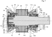
- the second bearing assembly 16 at the drive end of the electric machine comprises a bearing cartridge 144 integral with the fixed labyrinth seal ring 228, an outer race ring 146 force fitted into the bearing cartridge 144, an inner race ring 148 force fitted onto the rotor shaft 14 and rolling elements 150 between the inner race ring 148 and outer race ring 146.
- the rolling elements are cylindrical rollers and the races of the inner race ring 148 and outer race ring 46 are cylindrical.
- the inner race ring 148 bears axially against a shoulder 152 of the rotor shaft 14.
- the bearing cartridge 144 bears axially against an outer side 160 of the bearing shield 126 and is provided with a set of several, preferably three or more, mounting through holes 162 distributed over the circumference of the bearing cartridge 144 and extending in a direction parallel to the revolution axis 100.
- the mounting through holes 162 are aligned with intermediate through holes of the bearing shield 126 and threaded holes 165 of the fixed labyrinth seal ring 128.
- Fastening bolts 166 are inserted into the mounting through holes 162 of the bearing cartridge 144 and screwed into the threaded holes 164 of the bearing shield 126 to fasten the bearing cartridge 144 to the bearing shield 126.
- the bearing cartridge 144 is further provided with a set of several, preferably three or more, clearance through holes 168 distributed over the circumference of the bearing cartridge 144, illustrated in figure 5 , which are parallel to the revolution axis 100 and aligned with through holes 170, 172 of the bearing shield assembly 124, in this embodiment through the bearing shield 126 and the fixed labyrinth seal ring 128.
- These clearance through holes 168 can be aligned with threaded holes 174 of the rotor 14 when the rotor 14 is in an indexed angular position relative to the stator 12.
- the clearance through holes 168 have a diameter greater than the through holes 170, 172 of the bearing shield assembly and threaded holes 174 of the rotor.
- a sealed lubrication volume 180 is formed between the inner and outer race rings 48, 46, sealed at the one axial end by the labyrinth seal formed by the fixed labyrinth seal ring 128 and rotatable labyrinth seal ring 134 and sealed at the opposite axial end by the labyrinth seal formed by the fixed labyrinth seal ring 228 integral with the bearing cartridge 144 and rotatable labyrinth seal ring 34.
- This lubrication volume can be filled with a lubricant, preferably grease.
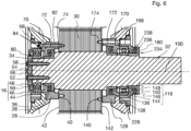
- the rotor 14 is rotated to the indexed angular position, and locking bolts 82 are inserted into the clearance through holes 68 (see figure 2 ) and in the through holes 70, 72 of the bearing shield assembly 24 .
- the locking bolts 82 are screwed into the threaded holes 74 of the rotor 14, until a cylindrical bolt head 84 of the locking bolts 82 bears axially against an edge 86 of the through holes 70 of the bearing shield 26 as illustrated in figure 6 .
- the shanks of the locking bolts 82 are in contact with the inner walls of the through holes 70, 72 of the bearing shield 24 and fixed labyrinth seal ring 28 and ensure a centred positioning of the rotor 14 relative to the revolution axis 10 independent from the bearing assembly 16.
- the mounting bolts 66 can therefore be at least partially unscrewed to allow a limited translation movement of the rotor 14 relative to the stator 12.
- the locking bolts 82 are further tightened until the tensile loaded locking bolts 82 provide sufficient pressure between the contact faces 40, 42 and the rotor 14 is locked by the frictional engagement of the contact faces 40, 42.
- no contact occurs between the interleaved ribs 36, 38 of the fixed labyrinth seal ring and movable labyrinth seal ring, because D2 ⁇ D1.
- no contact occurs between the interleaved ribs 136, 138, 236, 238 of the fixed labyrinth seal rings 128, 228 and movable labyrinth seal rings 134, 234, because D2 ⁇ D11.
- the cylindrical roller 150 slide on the race of the inner race ring 148.
- the mounting bolts 66 can be fully unscrewed and removed as well as the bolts 58.
- the bearing cartridge 76, outer race ring 46 and rolling bodies 50 can be removed before a ring puller is inserted to reach the remote end face of the inner ring 48 and pull the inner race ring 48.
- the rotor 14 is rotated to the indexed angular position, and, optionally, a threaded indexing rod 90 is inserted into the clearance through holes 68 and in the through holes 70, 72 of the bearing shield assembly 24 and screwed into the threaded holes 74 of the rotor 14, as illustrated in figure 9 .
- the shanks of the indexing rod 90 are in contact with the inner walls of the through holes 70, 72 of the bearing shield 24 and fixed labyrinth seal ring 28 and ensure a centred positioning of the rotor 14 relative to the revolution axis 10 independent from the bearing assembly 16.
- the mounting bolts 66 can therefore be at least partially unscrewed to allow a limited translation movement of the rotor 14 relative to the stator 12.
- Locking bolts 182 are inserted into the clearance through holes 168 and in the through holes 170, 172 of the bearing shield assembly 124 and screwed into the threaded holes 174 of the rotor 14, until a cylindrical bolt head 184 of the locking bolts 182 bears axially against an edge 186 of the through holes 170 of the bearing shield 126 as illustrated in figures 9 .
- the shanks of the locking bolts 182 are in contact with the inner walls of the through holes 170, 172 of the bearing shield 124 and fixed labyrinth seal ring 128 and ensure a centred positioning of the rotor 14 relative to the revolution axis 10 independent from the bearing assembly 116.
- the mounting bolts 166 can therefore be at least partially unscrewed to allow a limited translation movement of the rotor 14 relative to the stator 12.
- the locking bolts 182 are further tightened until the tensile loaded locking bolts 182 provide sufficient pressure between the contact faces 140, 142 and the rotor 14 is locked by the frictional engagement of the contact faces 140, 142.
- no contact occurs between the interleaved ribs 136, 138, 236, 238 of the fixed labyrinth seal ring and movable labyrinth seal ring, because of the fixed labyrinth seal rings 128, 228 and movable labyrinth seal rings 134, 234, because D12 ⁇ D11.
- the bearing assembly 16 at the non-drive end of the electric machine 10 moves with the rotor 14 and the thrust washer 54 and pushes the fixed labyrinth seal ring 28 away from the bearing shield 26, while the relative angular position between both parts is maintained by the indexing rod 90.
- the movable labyrinth seal ring 223 can then be pulled out as shown in figure 9 , and the bearing cartridge 176, outer race ring 146 and rolling bodies 150 can be removed before a ring puller is inserted to reach the remote end face of the inner ring 148 and pull the inner race ring 148.
- the bearing shields 26, 126 are preferably metallic.
- the fixed labyrinth seal rings 28, 128, 228 are preferably made of an electric insulation material, so that no electric path is generated when the contact surfaces 40, 42, 140, 142 touch each other.
- the subsequent tightening of the locking bolts 82 after the step of figure 4 may result in an elastic deformation of the bearing shield 26, which results in a contact between the contact faces 40, 42 without translation of the rotor 14 relative to the stator 12.
- a deformation of the rotor press plate in which the threaded holes 74 are located can take place.
- a clearance may be preserved between the shanks of the locking bolts 82 and the through holes 70, 72 of the bearing shield 24 and fixed labyrinth seal ring 28, in which case the centred positioning of the rotor 14 relative to the revolution axis 10 when the mounting bolts 66 are removed is provided by the bearing assembly 16.
Landscapes
- Engineering & Computer Science (AREA)
- General Engineering & Computer Science (AREA)
- Mechanical Engineering (AREA)
- Power Engineering (AREA)
- Motor Or Generator Frames (AREA)
Claims (15)
- Elektrische Maschine (10), umfassend:- einen Stator (12) umfassend eine Lagerschildanordnung (24, 124) umfassend ein Lagerschild (26, 126) und einen festen Labyrinthdichtungsring (28, 128), der eine verschlungene Labyrinthoberfläche (36, 136) aufweist,- einen Rotor (14), der um eine Drehachse (100) relativ zu dem Stator (12) drehbar ist, der Rotor (14) umfassend eine Rotorwelle (32) und einen drehbaren Labyrinthdichtungsring (34, 134), der an der Rotorwelle (14) montiert ist, wobei der drehbare Labyrinthdichtungsring (34, 134) eine der verschlungenen Labyrinthoberfläche (36, 136) des festen Labyrinthdichtungsrings (28, 128) zugewandte verschlungene Labyrinthoberfläche (38, 138) in einem ersten minimalen axialen Abstand (D1, D11) der verschlungenen Labyrinthoberfläche (36, 136) des festen Labyrinthdichtungsrings (28, 128) aufweist, um ein ringförmiges Labyrinth zwischen der verschlungenen Labyrinthoberfläche (36, 136) des festen Labyrinthdichtungsrings (28, 128) und der verschlungenen Labyrinthoberfläche (38, 138) des drehbaren Labyrinthdichtungsrings (34, 134) zu bilden, und- eine Lageranordnung (16, 116), die lösbar zwischen der Lagerschildanordnung (24, 124) und der Rotorwelle (32) montiert ist, um eine Drehbewegung des Rotors (14) relativ zu dem Stator (12) um die Drehachse (100) zu führen,dadurch gekennzeichnet, dass die Lagerschildanordnung (24, 124) mit einer festen Kontaktfläche (40, 140) bereitgestellt ist und der Rotor (14) ferner eine gegenüberliegende Kontaktfläche (42, 142) umfasst, die axial der festen Kontaktfläche (40, 140) der Lagerschildanordnung (24, 124) in einem zweiten axialen Abstand (D2, D12) der festen Kontaktfläche (40, 140) der Lagerschildanordnung (24, 124) zugewandt ist, wobei der zweite axiale Abstand (D2, D12) kürzer als der erste minimale axiale Abstand (D1, D11) ist.
- Elektrische Maschine (10) nach Anspruch 1, wobei die Lageranordnung (16, 116) eine Lagerpatrone (44, 144), einen Außenlaufring (46, 146), der in die Lagerpatrone (44, 144) angebracht ist, und einen Innenlaufring (48, 148), der auf der Rotorwelle (32) angebracht ist, umfasst.
- Elektrische Maschine (10) nach Anspruch 2, wobei die Lagerpatrone (44, 144) mit Montagedurchgangslöchern (62, 162) parallel zur Drehachse (100) bereitgestellt ist und mit Gewindelöchern (65, 165) der Lagerschildanordnung (24, 124) ausgerichtet ist, wobei die Lageranordnung (16, 116) Sicherungsbolzen (66, 166) umfasst, die in die Montagedurchgangslöcher (62, 162) der Lagerpatrone (44, 144) eingesetzt und in die Gewindelöcher (65, 165) der Lagerschildanordnung (24, 124) eingeschraubt sind, um die Lagerpatrone (44, 144) an der Lagerschildanordnung (24, 124) zu sichern.
- Elektrische Maschine (10) nach einem der Ansprüche 2 bis 3, wobei die Lagerpatrone (44, 144) mit Spieldurchgangslöchern (68, 168) bereitgestellt ist, die parallel zu der Drehachse (100) liegen und mit Durchgangslöchern (70, 72, 170, 172) der Lagerschildanordnung (24, 124) ausgerichtet sind, und die mit Gewindelöchern (74, 174) des Rotors (14) in einer indizierten Winkelposition des Rotors (14) relativ zu dem Stator (12) ausgerichtet werden können, wobei die Spieldurchgangslöcher (68, 168) einen Durchmesser aufweisen, der größer als die Durchgangslöcher (70, 72, 170, 172) der Lagerschildanordnung und die Gewindelöcher (74, 174) des Rotors (14) ist, sodass in der indizierten Winkelposition Verriegelungsbolzen (82, 182) in die Spieldurchgangslöcher (68, 168) und in die Durchgangslöcher (70, 72, 170, 172) der Lagerschildanordnung (24, 124) eingesetzt und in die Gewindelöcher (74, 174) des Rotors (14) eingeschraubt werden können, wobei ein zylindrischer Bolzenkopf (84) der Verriegelungsbolzen (82) axial gegen einen Rand der Durchgangslöcher (70, 72, 170, 172) der Lagerschildanordnung (24) gelagert ist.
- Elektrische Maschine (10) nach einem der Ansprüche 2 bis 4, ferner umfassend eine Druckscheibe (54), die lösbar an einem Ende der Rotorwelle (32) befestigt ist, um axial gegen den inneren Laufring (48) der Lageranordnung (16) gelagert zu sein.
- Elektrische Maschine (10) nach einem der Ansprüche 2 bis 5, wobei die Lageranordnung (10) Rollelemente (50, 150) zwischen dem Außenlaufring (46, 146) und dem Innenlaufring (48, 148) umfasst.
- Elektrische Maschine (10) nach einem der Ansprüche 2 bis 6, wobei ein mit Schmiermittel gefüllter Innenlagerraum (80, 180) zwischen dem Innenlaufring (48, 148) und dem Außenlaufring (50, 150) gebildet und durch das zwischen dem festen Labyrinthdichtungsring (28, 128) und dem drehbaren Labyrinthdichtungsring (34, 134) gebildete ringförmige Labyrinth abgedichtet ist.
- Elektrische Maschine (10) nach einem der Ansprüche 2 bis 7, ferner umfassend eine äußere Lagerabdeckung (76), die lösbar an der Lagerschildanordnung (24) befestigt ist.
- Elektrische Maschine (10) nach einem der vorstehenden Ansprüche, wobei die feste Kontaktfläche (40, 140) aus einem elektrischen Isoliermaterial hergestellt ist.
- Elektrische Maschine (10) nach einem der vorstehenden Ansprüche, wobei die gegenüberliegende Kontaktfläche (42, 142) aus einem elektrischen Isoliermaterial hergestellt ist.
- Elektrische Maschine nach einem der Ansprüche 1 bis 10, wobei die feste Kontaktfläche (40, 140) einstückig mit dem festen Labyrinthdichtungsring (28, 128) hergestellt ist.
- Elektrische Maschine nach einem der Ansprüche 1 bis 10, wobei die feste Kontaktfläche (40, 140) an dem Lagerschild (26, 126) ausgebildet ist.
- Elektrische Maschine (10) nach einem der vorstehenden Ansprüche, wobei die feste Kontaktfläche (40, 140) mindestens einen ebenen Abschnitt einschließt, der einem ebenen Abschnitt der gegenüberliegenden Kontaktfläche (42, 142) in dem zweiten axialen Abstand zugewandt ist.
- Elektrische Maschine (10) nach einem der vorstehenden Ansprüche, wobei der feste Labyrinthdichtungsring (28, 128) und der drehbare Labyrinthdichtungsring (34, 134) mit verschachtelten röhrenförmigen Rippen (36, 38, 136, 138) bereitgestellt sind, die mit der Drehachse (100) ausgerichtet sind, wobei das Labyrinth durch einen durchgehenden ringförmigen Raum zwischen den verschachtelten röhrenförmigen Rippen (36, 38, 136, 138) gebildet wird.
- Elektrische Maschine (10) nach einem der vorstehenden Ansprüche, wobei die elektrische Maschine (10) ein Antriebsmotor eines Schienenfahrzeugs ist.
Applications Claiming Priority (2)
| Application Number | Priority Date | Filing Date | Title |
|---|---|---|---|
| EP19020729 | 2019-12-31 | ||
| PCT/EP2020/088080 WO2021136834A1 (en) | 2019-12-31 | 2020-12-31 | Electric machine provided with a releasable bearing assembly |
Publications (2)
| Publication Number | Publication Date |
|---|---|
| EP4085203A1 EP4085203A1 (de) | 2022-11-09 |
| EP4085203B1 true EP4085203B1 (de) | 2023-09-20 |
Family
ID=69143378
Family Applications (1)
| Application Number | Title | Priority Date | Filing Date |
|---|---|---|---|
| EP20841744.4A Active EP4085203B1 (de) | 2019-12-31 | 2020-12-31 | Elektrische maschine, die mit einer lösbaren lageranordnung versehen ist |
Country Status (5)
| Country | Link |
|---|---|
| EP (1) | EP4085203B1 (de) |
| JP (1) | JP7808035B2 (de) |
| CN (1) | CN114846249B (de) |
| ES (1) | ES2967639T3 (de) |
| WO (1) | WO2021136834A1 (de) |
Families Citing this family (4)
| Publication number | Priority date | Publication date | Assignee | Title |
|---|---|---|---|---|
| CN113691070B (zh) * | 2021-08-25 | 2022-07-05 | 中车株洲电机有限公司 | 一种电机结构及其轴承更换方法 |
| CN114337045A (zh) * | 2021-11-25 | 2022-04-12 | 中车永济电机有限公司 | 一种可实现轴承防护的电机 |
| US12107475B2 (en) | 2022-05-06 | 2024-10-01 | Ford Global Technologies, Llc | Vehicle and electric machine configuration for a vehicle |
| DE102022211158B4 (de) * | 2022-10-20 | 2025-02-13 | Baumüller Nürnberg GmbH | Lagereinheit |
Family Cites Families (12)
| Publication number | Priority date | Publication date | Assignee | Title |
|---|---|---|---|---|
| US2972470A (en) * | 1958-11-03 | 1961-02-21 | Gen Motors Corp | Turbine construction |
| JPS59216439A (ja) * | 1983-05-19 | 1984-12-06 | Hitachi Ltd | 回転電機の軸受装置 |
| JP5098258B2 (ja) * | 2006-09-04 | 2012-12-12 | シンフォニアテクノロジー株式会社 | ダイナモ試験装置用回転電機 |
| JP5288982B2 (ja) * | 2008-10-07 | 2013-09-11 | 株式会社東芝 | 電動機 |
| JP5599194B2 (ja) * | 2010-01-29 | 2014-10-01 | ミネベア株式会社 | 軸受装置 |
| JP5574743B2 (ja) * | 2010-02-19 | 2014-08-20 | 株式会社東芝 | 電動機 |
| KR101439800B1 (ko) * | 2010-10-06 | 2014-09-16 | 미쓰비시덴키 가부시키가이샤 | 회전전기, 베어링 착탈용 치구 및 베어링 교환방법 |
| JP5287903B2 (ja) * | 2011-02-28 | 2013-09-11 | 株式会社安川電機 | ロータユニット、風力発電システム、回転電機、発電機および回転電機の組立方法 |
| AT512325B1 (de) * | 2011-12-30 | 2014-03-15 | Traktionssysteme Austria Gmbh | Elektrische maschine |
| CN102878207B (zh) * | 2012-09-25 | 2016-01-20 | 济钢集团有限公司 | 一种轧机轧辊的轴承座密封装置 |
| JP6140104B2 (ja) * | 2014-05-22 | 2017-05-31 | ファナック株式会社 | エアパージ機能を有する電動機 |
| CN108223589B (zh) * | 2018-02-07 | 2023-10-31 | 广州市拓道新材料科技有限公司 | 一种轴承密封装置 |
-
2020
- 2020-12-31 CN CN202080089778.8A patent/CN114846249B/zh active Active
- 2020-12-31 WO PCT/EP2020/088080 patent/WO2021136834A1/en not_active Ceased
- 2020-12-31 ES ES20841744T patent/ES2967639T3/es active Active
- 2020-12-31 EP EP20841744.4A patent/EP4085203B1/de active Active
- 2020-12-31 JP JP2022540458A patent/JP7808035B2/ja active Active
Also Published As
| Publication number | Publication date |
|---|---|
| JP2023508557A (ja) | 2023-03-02 |
| JP7808035B2 (ja) | 2026-01-28 |
| ES2967639T3 (es) | 2024-05-03 |
| EP4085203A1 (de) | 2022-11-09 |
| WO2021136834A1 (en) | 2021-07-08 |
| CN114846249A (zh) | 2022-08-02 |
| CN114846249B (zh) | 2025-09-09 |
Similar Documents
| Publication | Publication Date | Title |
|---|---|---|
| EP4085203B1 (de) | Elektrische maschine, die mit einer lösbaren lageranordnung versehen ist | |
| US20200032653A1 (en) | Retention of a rotor of an electronically-controlled turbomachine | |
| EP2829756B1 (de) | Hilfskugellager für ein magnetisch aufgehängtes Rotorsystem | |
| US9309922B2 (en) | Set of rolling bearings and corresponding rotary machine | |
| US9882447B2 (en) | Electric machine, assembly and associated method | |
| KR20180014162A (ko) | 전동기 | |
| EP4105504A1 (de) | Magnetische aufhängungslagervorrichtung, verdichter und verfahren zum einstellen des spaltes eines fanglagers | |
| KR101992818B1 (ko) | 모터 구조 | |
| US20230163668A1 (en) | Electric machine assembly and method for locking rotor to stator | |
| CN113691070B (zh) | 一种电机结构及其轴承更换方法 | |
| CN110905982B (zh) | 用于张紧辊或卷绕辊的带轮装置 | |
| TWI612229B (zh) | 組合滾珠軸承、主軸裝置及工作機械 | |
| JP7195723B2 (ja) | 分解可能な電気モータ | |
| US3930695A (en) | Race securing device | |
| US20020015543A1 (en) | Rolling contact bearing for an electric motor | |
| JPH0868375A (ja) | 間隙制御の特徴を有する回転装置 | |
| CN102969822B (zh) | 一种轴承可更换的电机结构及电机轴承更换方法 | |
| EP4484785A1 (de) | Wellenverriegelungssystem | |
| JP6500759B2 (ja) | 圧入治具 | |
| CN222262380U (zh) | 一种中空电机 | |
| JP5041147B2 (ja) | 電動モータ | |
| JP5041146B2 (ja) | 電動モータ | |
| JP2009281318A (ja) | ポンプ及びポンプの組立方法 | |
| CN110345213B (zh) | 用于张紧辊或卷绕辊的带轮装置 | |
| CN109891719B (zh) | 具有用于轴的轴向阻挡的系统的机器 |
Legal Events
| Date | Code | Title | Description |
|---|---|---|---|
| STAA | Information on the status of an ep patent application or granted ep patent |
Free format text: STATUS: UNKNOWN |
|
| STAA | Information on the status of an ep patent application or granted ep patent |
Free format text: STATUS: THE INTERNATIONAL PUBLICATION HAS BEEN MADE |
|
| PUAI | Public reference made under article 153(3) epc to a published international application that has entered the european phase |
Free format text: ORIGINAL CODE: 0009012 |
|
| STAA | Information on the status of an ep patent application or granted ep patent |
Free format text: STATUS: REQUEST FOR EXAMINATION WAS MADE |
|
| 17P | Request for examination filed |
Effective date: 20220511 |
|
| AK | Designated contracting states |
Kind code of ref document: A1 Designated state(s): AL AT BE BG CH CY CZ DE DK EE ES FI FR GB GR HR HU IE IS IT LI LT LU LV MC MK MT NL NO PL PT RO RS SE SI SK SM TR |
|
| DAV | Request for validation of the european patent (deleted) | ||
| DAX | Request for extension of the european patent (deleted) | ||
| GRAP | Despatch of communication of intention to grant a patent |
Free format text: ORIGINAL CODE: EPIDOSNIGR1 |
|
| STAA | Information on the status of an ep patent application or granted ep patent |
Free format text: STATUS: GRANT OF PATENT IS INTENDED |
|
| INTG | Intention to grant announced |
Effective date: 20230426 |
|
| GRAS | Grant fee paid |
Free format text: ORIGINAL CODE: EPIDOSNIGR3 |
|
| GRAA | (expected) grant |
Free format text: ORIGINAL CODE: 0009210 |
|
| STAA | Information on the status of an ep patent application or granted ep patent |
Free format text: STATUS: THE PATENT HAS BEEN GRANTED |
|
| RAP1 | Party data changed (applicant data changed or rights of an application transferred) |
Owner name: ALSTOM HOLDINGS |
|
| AK | Designated contracting states |
Kind code of ref document: B1 Designated state(s): AL AT BE BG CH CY CZ DE DK EE ES FI FR GB GR HR HU IE IS IT LI LT LU LV MC MK MT NL NO PL PT RO RS SE SI SK SM TR |
|
| REG | Reference to a national code |
Ref country code: GB Ref legal event code: FG4D |
|
| P01 | Opt-out of the competence of the unified patent court (upc) registered |
Effective date: 20230822 |
|
| REG | Reference to a national code |
Ref country code: CH Ref legal event code: EP |
|
| REG | Reference to a national code |
Ref country code: IE Ref legal event code: FG4D |
|
| REG | Reference to a national code |
Ref country code: DE Ref legal event code: R096 Ref document number: 602020018072 Country of ref document: DE |
|
| REG | Reference to a national code |
Ref country code: SE Ref legal event code: TRGR |
|
| REG | Reference to a national code |
Ref country code: LT Ref legal event code: MG9D |
|
| PG25 | Lapsed in a contracting state [announced via postgrant information from national office to epo] |
Ref country code: GR Free format text: LAPSE BECAUSE OF FAILURE TO SUBMIT A TRANSLATION OF THE DESCRIPTION OR TO PAY THE FEE WITHIN THE PRESCRIBED TIME-LIMIT Effective date: 20231221 |
|
| REG | Reference to a national code |
Ref country code: NL Ref legal event code: MP Effective date: 20230920 |
|
| PG25 | Lapsed in a contracting state [announced via postgrant information from national office to epo] |
Ref country code: RS Free format text: LAPSE BECAUSE OF FAILURE TO SUBMIT A TRANSLATION OF THE DESCRIPTION OR TO PAY THE FEE WITHIN THE PRESCRIBED TIME-LIMIT Effective date: 20230920 Ref country code: NO Free format text: LAPSE BECAUSE OF FAILURE TO SUBMIT A TRANSLATION OF THE DESCRIPTION OR TO PAY THE FEE WITHIN THE PRESCRIBED TIME-LIMIT Effective date: 20231220 Ref country code: LV Free format text: LAPSE BECAUSE OF FAILURE TO SUBMIT A TRANSLATION OF THE DESCRIPTION OR TO PAY THE FEE WITHIN THE PRESCRIBED TIME-LIMIT Effective date: 20230920 Ref country code: LT Free format text: LAPSE BECAUSE OF FAILURE TO SUBMIT A TRANSLATION OF THE DESCRIPTION OR TO PAY THE FEE WITHIN THE PRESCRIBED TIME-LIMIT Effective date: 20230920 Ref country code: HR Free format text: LAPSE BECAUSE OF FAILURE TO SUBMIT A TRANSLATION OF THE DESCRIPTION OR TO PAY THE FEE WITHIN THE PRESCRIBED TIME-LIMIT Effective date: 20230920 Ref country code: GR Free format text: LAPSE BECAUSE OF FAILURE TO SUBMIT A TRANSLATION OF THE DESCRIPTION OR TO PAY THE FEE WITHIN THE PRESCRIBED TIME-LIMIT Effective date: 20231221 Ref country code: FI Free format text: LAPSE BECAUSE OF FAILURE TO SUBMIT A TRANSLATION OF THE DESCRIPTION OR TO PAY THE FEE WITHIN THE PRESCRIBED TIME-LIMIT Effective date: 20230920 |
|
| PG25 | Lapsed in a contracting state [announced via postgrant information from national office to epo] |
Ref country code: NL Free format text: LAPSE BECAUSE OF FAILURE TO SUBMIT A TRANSLATION OF THE DESCRIPTION OR TO PAY THE FEE WITHIN THE PRESCRIBED TIME-LIMIT Effective date: 20230920 |
|
| PG25 | Lapsed in a contracting state [announced via postgrant information from national office to epo] |
Ref country code: IS Free format text: LAPSE BECAUSE OF FAILURE TO SUBMIT A TRANSLATION OF THE DESCRIPTION OR TO PAY THE FEE WITHIN THE PRESCRIBED TIME-LIMIT Effective date: 20240120 |
|
| REG | Reference to a national code |
Ref country code: AT Ref legal event code: UEP Ref document number: 1613596 Country of ref document: AT Kind code of ref document: T Effective date: 20230920 |
|
| PG25 | Lapsed in a contracting state [announced via postgrant information from national office to epo] |
Ref country code: SM Free format text: LAPSE BECAUSE OF FAILURE TO SUBMIT A TRANSLATION OF THE DESCRIPTION OR TO PAY THE FEE WITHIN THE PRESCRIBED TIME-LIMIT Effective date: 20230920 Ref country code: RO Free format text: LAPSE BECAUSE OF FAILURE TO SUBMIT A TRANSLATION OF THE DESCRIPTION OR TO PAY THE FEE WITHIN THE PRESCRIBED TIME-LIMIT Effective date: 20230920 Ref country code: IS Free format text: LAPSE BECAUSE OF FAILURE TO SUBMIT A TRANSLATION OF THE DESCRIPTION OR TO PAY THE FEE WITHIN THE PRESCRIBED TIME-LIMIT Effective date: 20240120 Ref country code: EE Free format text: LAPSE BECAUSE OF FAILURE TO SUBMIT A TRANSLATION OF THE DESCRIPTION OR TO PAY THE FEE WITHIN THE PRESCRIBED TIME-LIMIT Effective date: 20230920 Ref country code: SK Free format text: LAPSE BECAUSE OF FAILURE TO SUBMIT A TRANSLATION OF THE DESCRIPTION OR TO PAY THE FEE WITHIN THE PRESCRIBED TIME-LIMIT Effective date: 20230920 Ref country code: PT Free format text: LAPSE BECAUSE OF FAILURE TO SUBMIT A TRANSLATION OF THE DESCRIPTION OR TO PAY THE FEE WITHIN THE PRESCRIBED TIME-LIMIT Effective date: 20240122 |
|
| REG | Reference to a national code |
Ref country code: ES Ref legal event code: FG2A Ref document number: 2967639 Country of ref document: ES Kind code of ref document: T3 Effective date: 20240503 |
|
| PG25 | Lapsed in a contracting state [announced via postgrant information from national office to epo] |
Ref country code: PL Free format text: LAPSE BECAUSE OF FAILURE TO SUBMIT A TRANSLATION OF THE DESCRIPTION OR TO PAY THE FEE WITHIN THE PRESCRIBED TIME-LIMIT Effective date: 20230920 Ref country code: IT Free format text: LAPSE BECAUSE OF FAILURE TO SUBMIT A TRANSLATION OF THE DESCRIPTION OR TO PAY THE FEE WITHIN THE PRESCRIBED TIME-LIMIT Effective date: 20230920 |
|
| REG | Reference to a national code |
Ref country code: DE Ref legal event code: R097 Ref document number: 602020018072 Country of ref document: DE |
|
| PG25 | Lapsed in a contracting state [announced via postgrant information from national office to epo] |
Ref country code: DK Free format text: LAPSE BECAUSE OF FAILURE TO SUBMIT A TRANSLATION OF THE DESCRIPTION OR TO PAY THE FEE WITHIN THE PRESCRIBED TIME-LIMIT Effective date: 20230920 |
|
| PLBE | No opposition filed within time limit |
Free format text: ORIGINAL CODE: 0009261 |
|
| STAA | Information on the status of an ep patent application or granted ep patent |
Free format text: STATUS: NO OPPOSITION FILED WITHIN TIME LIMIT |
|
| PG25 | Lapsed in a contracting state [announced via postgrant information from national office to epo] |
Ref country code: DK Free format text: LAPSE BECAUSE OF FAILURE TO SUBMIT A TRANSLATION OF THE DESCRIPTION OR TO PAY THE FEE WITHIN THE PRESCRIBED TIME-LIMIT Effective date: 20230920 |
|
| REG | Reference to a national code |
Ref country code: CH Ref legal event code: PL |
|
| PG25 | Lapsed in a contracting state [announced via postgrant information from national office to epo] |
Ref country code: LU Free format text: LAPSE BECAUSE OF NON-PAYMENT OF DUE FEES Effective date: 20231231 |
|
| PG25 | Lapsed in a contracting state [announced via postgrant information from national office to epo] |
Ref country code: MC Free format text: LAPSE BECAUSE OF FAILURE TO SUBMIT A TRANSLATION OF THE DESCRIPTION OR TO PAY THE FEE WITHIN THE PRESCRIBED TIME-LIMIT Effective date: 20230920 |
|
| 26N | No opposition filed |
Effective date: 20240621 |
|
| REG | Reference to a national code |
Ref country code: BE Ref legal event code: MM Effective date: 20231231 |
|
| PG25 | Lapsed in a contracting state [announced via postgrant information from national office to epo] |
Ref country code: MC Free format text: LAPSE BECAUSE OF FAILURE TO SUBMIT A TRANSLATION OF THE DESCRIPTION OR TO PAY THE FEE WITHIN THE PRESCRIBED TIME-LIMIT Effective date: 20230920 Ref country code: LU Free format text: LAPSE BECAUSE OF NON-PAYMENT OF DUE FEES Effective date: 20231231 |
|
| REG | Reference to a national code |
Ref country code: IE Ref legal event code: MM4A |
|
| PG25 | Lapsed in a contracting state [announced via postgrant information from national office to epo] |
Ref country code: IE Free format text: LAPSE BECAUSE OF NON-PAYMENT OF DUE FEES Effective date: 20231231 |
|
| PG25 | Lapsed in a contracting state [announced via postgrant information from national office to epo] |
Ref country code: BE Free format text: LAPSE BECAUSE OF NON-PAYMENT OF DUE FEES Effective date: 20231231 |
|
| PG25 | Lapsed in a contracting state [announced via postgrant information from national office to epo] |
Ref country code: FR Free format text: LAPSE BECAUSE OF NON-PAYMENT OF DUE FEES Effective date: 20231231 |
|
| PG25 | Lapsed in a contracting state [announced via postgrant information from national office to epo] |
Ref country code: CH Free format text: LAPSE BECAUSE OF NON-PAYMENT OF DUE FEES Effective date: 20231231 |
|
| PG25 | Lapsed in a contracting state [announced via postgrant information from national office to epo] |
Ref country code: SI Free format text: LAPSE BECAUSE OF FAILURE TO SUBMIT A TRANSLATION OF THE DESCRIPTION OR TO PAY THE FEE WITHIN THE PRESCRIBED TIME-LIMIT Effective date: 20230920 |
|
| PG25 | Lapsed in a contracting state [announced via postgrant information from national office to epo] |
Ref country code: SI Free format text: LAPSE BECAUSE OF FAILURE TO SUBMIT A TRANSLATION OF THE DESCRIPTION OR TO PAY THE FEE WITHIN THE PRESCRIBED TIME-LIMIT Effective date: 20230920 Ref country code: IE Free format text: LAPSE BECAUSE OF NON-PAYMENT OF DUE FEES Effective date: 20231231 Ref country code: FR Free format text: LAPSE BECAUSE OF NON-PAYMENT OF DUE FEES Effective date: 20231231 Ref country code: CH Free format text: LAPSE BECAUSE OF NON-PAYMENT OF DUE FEES Effective date: 20231231 Ref country code: BE Free format text: LAPSE BECAUSE OF NON-PAYMENT OF DUE FEES Effective date: 20231231 |
|
| PG25 | Lapsed in a contracting state [announced via postgrant information from national office to epo] |
Ref country code: BG Free format text: LAPSE BECAUSE OF FAILURE TO SUBMIT A TRANSLATION OF THE DESCRIPTION OR TO PAY THE FEE WITHIN THE PRESCRIBED TIME-LIMIT Effective date: 20230920 |
|
| PG25 | Lapsed in a contracting state [announced via postgrant information from national office to epo] |
Ref country code: BG Free format text: LAPSE BECAUSE OF FAILURE TO SUBMIT A TRANSLATION OF THE DESCRIPTION OR TO PAY THE FEE WITHIN THE PRESCRIBED TIME-LIMIT Effective date: 20230920 |
|
| PGFP | Annual fee paid to national office [announced via postgrant information from national office to epo] |
Ref country code: ES Payment date: 20250131 Year of fee payment: 5 |
|
| PG25 | Lapsed in a contracting state [announced via postgrant information from national office to epo] |
Ref country code: CY Free format text: LAPSE BECAUSE OF FAILURE TO SUBMIT A TRANSLATION OF THE DESCRIPTION OR TO PAY THE FEE WITHIN THE PRESCRIBED TIME-LIMIT; INVALID AB INITIO Effective date: 20201231 |
|
| PG25 | Lapsed in a contracting state [announced via postgrant information from national office to epo] |
Ref country code: HU Free format text: LAPSE BECAUSE OF FAILURE TO SUBMIT A TRANSLATION OF THE DESCRIPTION OR TO PAY THE FEE WITHIN THE PRESCRIBED TIME-LIMIT; INVALID AB INITIO Effective date: 20201231 |
|
| GBPC | Gb: european patent ceased through non-payment of renewal fee |
Effective date: 20241231 |
|
| PG25 | Lapsed in a contracting state [announced via postgrant information from national office to epo] |
Ref country code: GB Free format text: LAPSE BECAUSE OF NON-PAYMENT OF DUE FEES Effective date: 20241231 |
|
| PG25 | Lapsed in a contracting state [announced via postgrant information from national office to epo] |
Ref country code: TR Free format text: LAPSE BECAUSE OF FAILURE TO SUBMIT A TRANSLATION OF THE DESCRIPTION OR TO PAY THE FEE WITHIN THE PRESCRIBED TIME-LIMIT Effective date: 20230920 |
|
| PGFP | Annual fee paid to national office [announced via postgrant information from national office to epo] |
Ref country code: DE Payment date: 20251211 Year of fee payment: 6 |
|
| PGFP | Annual fee paid to national office [announced via postgrant information from national office to epo] |
Ref country code: AT Payment date: 20251222 Year of fee payment: 6 |
|
| PGFP | Annual fee paid to national office [announced via postgrant information from national office to epo] |
Ref country code: SE Payment date: 20251219 Year of fee payment: 6 |
|
| PGFP | Annual fee paid to national office [announced via postgrant information from national office to epo] |
Ref country code: CZ Payment date: 20251223 Year of fee payment: 6 |