EP4084934B1 - Werkzeugmaschine und verfahren zu einem kühlen einer antriebseinheit der werkzeugmaschine - Google Patents
Werkzeugmaschine und verfahren zu einem kühlen einer antriebseinheit der werkzeugmaschine Download PDFInfo
- Publication number
- EP4084934B1 EP4084934B1 EP20816145.5A EP20816145A EP4084934B1 EP 4084934 B1 EP4084934 B1 EP 4084934B1 EP 20816145 A EP20816145 A EP 20816145A EP 4084934 B1 EP4084934 B1 EP 4084934B1
- Authority
- EP
- European Patent Office
- Prior art keywords
- unit
- fluid
- fluid cooling
- machine tool
- drive unit
- Prior art date
- Legal status (The legal status is an assumption and is not a legal conclusion. Google has not performed a legal analysis and makes no representation as to the accuracy of the status listed.)
- Active
Links
Images




Classifications
-
- B—PERFORMING OPERATIONS; TRANSPORTING
- B25—HAND TOOLS; PORTABLE POWER-DRIVEN TOOLS; MANIPULATORS
- B25F—COMBINATION OR MULTI-PURPOSE TOOLS NOT OTHERWISE PROVIDED FOR; DETAILS OR COMPONENTS OF PORTABLE POWER-DRIVEN TOOLS NOT PARTICULARLY RELATED TO THE OPERATIONS PERFORMED AND NOT OTHERWISE PROVIDED FOR
- B25F5/00—Details or components of portable power-driven tools not particularly related to the operations performed and not otherwise provided for
- B25F5/008—Cooling means
-
- B—PERFORMING OPERATIONS; TRANSPORTING
- B24—GRINDING; POLISHING
- B24B—MACHINES, DEVICES, OR PROCESSES FOR GRINDING OR POLISHING; DRESSING OR CONDITIONING OF ABRADING SURFACES; FEEDING OF GRINDING, POLISHING, OR LAPPING AGENTS
- B24B23/00—Portable grinding machines, e.g. hand-guided; Accessories therefor
- B24B23/02—Portable grinding machines, e.g. hand-guided; Accessories therefor with rotating grinding tools; Accessories therefor
- B24B23/028—Angle tools
-
- B—PERFORMING OPERATIONS; TRANSPORTING
- B24—GRINDING; POLISHING
- B24B—MACHINES, DEVICES, OR PROCESSES FOR GRINDING OR POLISHING; DRESSING OR CONDITIONING OF ABRADING SURFACES; FEEDING OF GRINDING, POLISHING, OR LAPPING AGENTS
- B24B55/00—Safety devices for grinding or polishing machines; Accessories fitted to grinding or polishing machines for keeping tools or parts of the machine in good working condition
- B24B55/02—Equipment for cooling the grinding surfaces, e.g. devices for feeding coolant
Definitions
- a machine tool with at least one housing unit, with at least one drive unit arranged within the housing unit and with at least one separation unit has already been proposed, wherein the separation unit is provided to divide at least one fluid flow conducted through the housing unit into at least two partial flows, wherein one partial flow of the partial flows has a higher foreign body density compared to another partial flow of the partial flows.
- EP 3 549 717 A1 discloses the preamble of claim 1.
- machine tools are from the JP-S58 49066 A , WO 2016/002542 A1 , DE 21 2013 000108 U1 or EN 10 2008 041370 A1 known.
- the invention relates to a machine tool, in particular a hand-held machine tool, according to claim 1.
- the term "intended” should be understood to mean, in particular, specially programmed, specially designed and/or specially equipped.
- the fact that an object, in particular the fluid cooling unit, is intended for a specific function, in particular to cool the drive unit by means of the at least two partial flows, should be understood to mean, in particular, that the object fulfills and/or carries out this specific function in at least one application and/or operating state.
- the fluid flow preferably comprises a large number of foreign bodies, with a number, volume and/or mass of foreign bodies per unit volume, for example per cm 3 , in the fluid flow indicating the foreign body density.
- the foreign bodies in the fluid flow and/or the partial flows are formed as dust particles, as residues from a machined workpiece, in particular metal chips, as impurities in the fluid flow or the like.
- the fluid flow and/or the partial flows are formed at least partially, in particular at least largely, from air.
- the fluid cooling unit preferably comprises at least one intake opening, which is delimited in particular by the housing unit.
- the intake opening is arranged on a side of the housing unit facing away from a processing area of the machine tool.
- the fluid cooling unit preferably comprises at least one outlet opening which is at least partially delimited by the housing unit and is preferably arranged at a distance from the intake opening.
- the partial flow and/or the other partial flow comprises a value for the foreign body density which is different from zero.
- the fluid cooling unit is preferably designed such that when the drive unit is cooled by means of the partial flows, in particular the partial flow and/or the further partial flow, thermal energy is transferred from the drive unit to the partial flows, in particular the partial flow or the further partial flow.
- the fluid cooling unit is preferably provided to conduct the heat transferred to the partial flows, in particular the partial flow or the further partial flow, out of the machine tool, in particular the housing unit, via the partial flows, in particular the partial flow or the further partial flow.
- the separation unit is preferably designed such that a value of the foreign body density of the partial flow is in particular at least 50%, preferably at least 70%, preferably at least 80% and particularly preferably at least 90% greater than a value of the foreign body density of the other partial flow, wherein in particular the foreign bodies have a size, in particular an average diameter, of at least 500 ⁇ m, preferably at least 100 ⁇ m and particularly preferably at least 20 ⁇ m.
- the separation unit is preferably provided to divide the fluid flow into the partial flow and the other partial flow via a geometric design of a guide path of the fluid flow, in particular the fluid flow that is sucked in, wherein in particular the partial flow has a higher foreign body density compared to the other partial flow.
- the separation unit is preferably provided to guide the partial flow and the other partial flow, in particular from the guide path to different partial guide paths.
- the fluid cooling unit is preferably provided to guide the fluid flow via the intake opening through at least one channel element to the separation unit.
- the channel element is arranged at least essentially completely within the housing unit. "Essentially completely” is to be understood in particular as an indication of a proportion of a component, in particular of the channel element, which has a certain property, in particular of being enclosed by the housing unit, wherein in particular at least 90%, preferably at least 95% and particularly preferably at least 98% of a total volume and/or a total mass of the component has the property.
- the separation unit and the fluid cooling unit are formed in one piece, wherein in particular a channel element of the fluid cooling unit is provided to limit the fluid flow on the guide path and/or the partial guide paths.
- At least one separation element of the separation unit is designed as a channel element of the fluid cooling unit and in particular limits at least one fluid channel to a line of the fluid.
- the term "one-piece" is to be understood in particular as materially bonded, such as by a welding process and/or adhesive process, etc., and particularly advantageously as integrally formed, such as by production from a single cast and/or by production in a single or multi-component injection molding process.
- the fluid cooling unit is provided to cool the partial flows after they have flowed through the separating unit to a Cooling of the drive unit at least partially towards the drive unit.
- the machine tool is preferably designed as a hand-held machine tool.
- the machine tool is designed as an angle grinder, a drill, a vacuum cleaner, a screwdriver or the like.
- the drive unit is designed as a motor, in particular an electric motor.
- the drive unit, the separation unit and/or the fluid cooling unit, in particular with the exception of the intake opening and/or the outlet opening, are arranged at least substantially completely within the housing unit.
- the design of the machine tool according to the invention enables advantageously effective cooling of the drive unit, in particular without soiling the drive unit, in particular since the partial flow and the other partial flow can be used to cool the drive unit.
- Advantageously high energy efficiency can be achieved when cooling the drive unit, in particular since a sucked-in fluid flow can be used entirely to cool the drive unit.
- the separation unit comprises at least one separation element designed as a channel element, which is arranged in a close area of the drive unit and is intended to divide the fluid flow.
- Advantageously effective cooling of the drive unit can be achieved by means of the partial flows.
- the separation element is intended to guide the fluid flow on the guide path and to divide it into the partial flow and the other partial flow.
- the separation element is designed as a passive element, wherein in particular the separation element is intended to divide the fluid flow via a shape of the separation element, in particular when the fluid flow flows through.
- the separation element is designed to be static or immobile.
- the separation element forms at least one fluid inlet for conducting the fluid flow and at least two fluid outlets for conducting of the partial flow or the other partial flow.
- the separating element has an at least partially curved basic shape in a sectional plane comprising the guide path and/or at least one of the partial guide paths.
- the separating element is designed such that the guide path in a region of the fluid inlet to the partial guide path of the other partial flow in a region of one of the fluid outlets has an angle of in particular at least 30°, preferably at least 60° and particularly preferably at least 80°.
- the separating element has at least one basic shape which is designed such that foreign bodies are guided onto a path deviating from a guide path of the fluid flow, in particular of the other partial flow.
- the separating element is designed such that the partial flow is guided at least partially separately from the other partial flow.
- the separating element is arranged on the fluid cooling unit or designed as part of the fluid cooling unit.
- the separating element is designed in one piece with the fluid cooling unit, in particular at least one channel element of the fluid cooling unit.
- the separation unit, in particular the separation element is fluidically arranged between the intake opening and the drive unit.
- the separation element is arranged in a close area of the drive unit
- the separation element is arranged, in particular completely, within an area around the drive unit which extends within a minimum distance of at most 150 mm, preferably at most 100 mm and particularly preferably at most 50 mm, around the drive unit.
- the separation element arranged in the close area of the drive unit is arranged, in particular fastened, directly to the drive unit, in particular to a housing of the drive unit. It is conceivable that the separation element arranged in the close area of the drive unit is formed in one piece with the drive unit, in particular the housing of the drive unit.
- the fluid cooling unit comprises at least one channel element, in particular the one mentioned above, which is intended to guide the partial flow, in particular separately from the other partial flow, at least partially past an outer wall of the drive unit.
- Contamination of the drive unit with foreign bodies in the partial flow can be prevented in the event of a Cooling of the drive unit with the partial flows can be advantageously prevented.
- Unwanted abrasive damage to the drive unit, in particular bearings and/or windings of the drive unit can be advantageously prevented.
- An advantageously long service life can be made possible.
- the separation unit and/or the fluid cooling unit are designed in such a way that the partial flow, in particular in an area along the drive unit, is guided through the housing unit at least largely separately from the other partial flow.
- the fluid cooling unit is preferably provided to guide the other partial flow into or through the drive unit for cooling the drive unit.
- the channel element is arranged outside the drive unit on the outer wall.
- the channel element is arranged directly on the drive unit, in particular the outer wall.
- the channel element lies flat against the outer wall.
- the channel element is provided to transfer heat from the drive unit, in particular the outer wall, to the partial flow, wherein in particular the drive unit is cooled by the partial flow.
- the channel element extends along an entire length of the drive element on the outer wall.
- the channel element is at least partially, in particular at least mostly, made of a heat-conducting material which in particular has a thermal conductivity of in particular at least 10 W/(m ⁇ K), preferably at least 40 W/(m ⁇ K), preferably at least 100 W/(m ⁇ K) and particularly preferably at least 200 W/(m ⁇ K).
- the channel element is at least substantially rectilinear, in particular along an entire length of the outer wall.
- the channel element is at least mostly arranged at least substantially parallel to the outer wall, in particular an outer surface of the outer wall which faces the channel element or at least partially rests against the channel element.
- substantially parallel is to be understood here as meaning in particular an alignment of a direction, in particular a main extension direction of the channel element, relative to a reference direction, in particular a main extension direction of the outer wall and/or the outer surface of the outer wall, wherein the direction compared to the reference direction, in particular viewed in at least one projection plane, has a deviation in particular of less than 8°, advantageously less than 5° and particularly advantageously less than 2°.
- a "main extension direction" of an object, in particular the outer wall and/or the outer surface of the outer wall should be understood in particular to mean a direction which runs parallel to a longest edge of a smallest geometric cuboid which just completely encloses the object.
- the separation unit comprises at least one conveying unit which is arranged within the fluid cooling unit and is intended to convey at least the partial flow out of or through the housing unit.
- Advantageously effective cooling can be achieved, in particular because high flow speeds of the fluid flows, in particular of the partial flows, can be enabled via the conveying unit. Distribution of foreign bodies from the partial flow within the housing unit, the separation unit and/or the fluid cooling unit, in particular into the other partial flow, can advantageously be prevented.
- the conveying unit is designed as a flow pump.
- the conveying unit is intended to suck in the partial flow via the fluid cooling unit, in particular through the intake opening.
- the conveying unit is intended to convey the fluid flow, in particular along the guide path, through the separation unit and to divide it into the partial flows, in particular the partial flow and the other partial flow, in particular by means of a conveying speed and the separation element.
- the conveying unit is preferably provided to convey the partial flows, in particular the partial flow and/or the other partial flow, in particular after cooling the drive unit, through the outlet opening out of the machine tool, in particular the housing unit.
- the conveying unit preferably comprises at least one conveying element, which is designed, for example, as a fan wheel, as a blade, as a piston or the like.
- the conveying element is preferably arranged at least partially, in particular at least largely, within the fluid cooling unit, in particular a channel element of the fluid cooling unit.
- the conveying element is preferably arranged behind the drive unit when viewed from the intake opening.
- the conveying element is formed in one piece with a fan of the drive unit.
- the conveying element is arranged between the separating unit and the drive unit or in front of the separating unit when viewed from the intake opening.
- the conveying unit in particular the Conveying element intended to convey the partial flow and/or the other partial flow through the fluid cooling unit, through the separation unit and/or out of the machine tool or the housing unit.
- the conveying unit comprises at least one conveying element which is designed as an axial fan.
- a fan wheel of the drive unit can advantageously be used as a conveying element for the partial flows.
- the conveying element designed as an axial fan is designed as part of the drive unit.
- the conveying element is preferably designed in one piece with a fan wheel of the drive unit.
- the conveying element is preferably arranged fluidically behind the drive unit as viewed from the intake opening.
- the conveying element is arranged in a channel element of the fluid cooling unit which is provided for guiding the partial flow.
- the conveying element is preferably arranged fluidically behind the separation unit as viewed from the intake opening.
- the conveying element is arranged within the partial guide section of the partial flow.
- the conveying unit is provided to convey the partial flow and the other partial flow separately from one another through the housing unit and/or the fluid cooling unit. Contamination of the drive unit with foreign bodies in the partial flow when the drive unit is cooled with the partial flows can advantageously be prevented. An advantageously effective separation of the partial flows can be made possible.
- the conveying unit in particular together with the fluid cooling unit, is provided to convey the partial flows in different directions.
- a conveying element of the conveying unit is designed as a radial fan in at least one region of the conveying element.
- the conveying element is designed as an axial fan in at least one further region of the conveying element.
- the region of the conveying element is enclosed by the further region when viewed along a drive axis of the conveying element.
- the region of the conveying element has a smaller minimum radial distance from the drive axis of the conveying element than the further region of the conveying element.
- the conveying element is designed as, in particular two-part fan wheel.
- the conveying element is particularly preferably arranged behind the drive unit, in particular in terms of fluid technology, preferably viewed from the intake opening.
- the conveying element is designed as part of the drive unit.
- the conveying element is preferably provided to convey the partial flow, in particular in a close area around the conveying element, in a direction that is at least substantially parallel to the drive axis of the conveying element.
- the conveying element is preferably provided to convey the other partial flow, in particular in a close area of the conveying element, in a direction that is at least substantially perpendicular to the drive axis of the conveying element.
- substantially perpendicular is to be understood in particular as an orientation of a direction, in particular a conveying direction of the other partial flow, relative to a reference direction, in particular a direction running along the drive axis of the conveying element, wherein the direction and the reference direction, in particular viewed in a projection plane, enclose an angle of 90° and the angle has a maximum deviation of in particular less than 8°, advantageously less than 5° and particularly advantageously less than 2°.
- the conveying unit is provided to convey the partial flow and the other partial flow out of the machine tool or the housing unit through differently designed and/or spaced-apart outlet openings of the fluid cooling unit.
- the separation unit comprises at least one, in particular a further, separation element, which is arranged within one, in particular a further, channel element, in particular a main channel element, of the fluid cooling unit and is intended to guide the fluid flow to a portion of the partial flows along the, in particular further, channel element on a circular path.
- a further, separation element which is arranged within one, in particular a further, channel element, in particular a main channel element, of the fluid cooling unit and is intended to guide the fluid flow to a portion of the partial flows along the, in particular further, channel element on a circular path.
- An advantageously compact design of the separation unit can be made possible, in particular because the further separation element can be arranged in the further channel element.
- An advantageously small amount of foreign bodies settling can be made possible, in particular because the further channel element can be designed with a flat inner wall.
- the further separation element is arranged at least substantially completely within the further channel element, in particular the main channel element.
- the further channel element in particular the main channel element, is tubular and/or hollow-cylindrical and in particular has at least one central axis.
- the central axis of the further channel element, in particular of the main channel element is arranged at least substantially parallel, in particular coaxially, to the drive axis, to a longitudinal axis of the machine tool, to a main extension axis of the fluid cooling unit and/or the machine tool and/or to a direction of propagation of the fluid flow within the fluid cooling unit.
- the further channel element, in particular of the main channel element is arranged, in particular from a fluid technology perspective, between the intake opening and the drive unit.
- the conveying unit in particular the conveying element, is particularly preferably provided to convey the fluid flow from the intake opening through the further channel element, in particular the main channel element, wherein the fluid flow is guided by means of the further separation element along the further channel element and/or the central axis of the further channel element onto the circular path.
- the fluid flow is divided into the partial flow and the other partial flow when flowing through the further channel element and the further separation element, in particular on the circular path, wherein in particular the partial flow is guided on a path through the further channel element which, in particular due to inertia, has a larger radius to the central axis than a path of the other partial flow through the further channel element.
- Foreign bodies in the partial flow preferably have a path which is a greater distance from a central axis of the further channel element than a path of the other partial flow.
- the separation element designed as a channel element is at least partially funnel-shaped and/or trumpet-shaped.
- the separation element designed as a channel element is arranged behind the further separation element when viewed from the intake opening.
- the separation element is at least partially conical.
- the separation element delimits at least one passage around a central axis of the separation element, which is provided in particular for a line of the other partial flow.
- the separating element is provided to separate the partial flow guided onto the circular path by means of the further separating element from the other partial flow, wherein in particular the partial flow is guided along an outer wall of the separating element into the channel element and wherein in particular the other partial flow is guided through the passage of the separation element onto and/or into the drive unit.
- the separation element is designed as a helical and/or screw-shaped molded part.
- An advantageously simple and cost-effective separation of the fluid flow into the partial flows can be achieved.
- An advantageously compact design of the machine tool, in particular of the fluid cooling unit and the separation unit can be made possible, in particular because the fluid flow can be divided within a straight fluid channel.
- An advantageously low wear of the fluid cooling unit and the separation unit, in particular of the inner walls, can be achieved, in particular because foreign bodies have a flatter angle to the inner walls of the fluid channels when the fluid flow is divided. This also advantageously enables small residues from foreign bodies within the fluid cooling unit.
- the further separation element in particular within and/or together with the further channel element, in particular the main channel element, delimits a fluid guide channel which extends from the intake opening in the direction of the drive unit along a curve which runs with a constant gradient around a jacket surface of an imaginary cylinder.
- the further separation element is designed as a single-start screw.
- the further separation element is designed as a two-start, three-start or multi-start screw.
- the further separation element has a central axis around which in particular the fluid guide channel is wound.
- the central axis of the further separation element is aligned coaxially with a central axis of the further channel element, in particular the main channel element, and/or with the central axis of the separation element, around which in particular the passage of the separation element is formed.
- the conveying unit comprises at least one, in particular a further, conveying element which is arranged, in particular fluidically, between the intake opening of the fluid cooling unit and the drive unit.
- the conveying element is arranged at least partially, in particular at least largely, within the fluid cooling unit, in particular a channel element of the fluid cooling unit.
- the fluid between the intake opening and the drive unit arranged conveying element is arranged between the separation unit and the drive unit or between the suction opening and the separation unit.
- the conveying element arranged between the suction opening and the drive unit is intended to convey the partial flow and/or the other partial flow through the fluid cooling unit, through the separation unit and/or out of the machine tool or the housing unit.
- the conveying unit comprises at least one, in particular the aforementioned or a further, conveying element which is designed as a spiral wheel.
- the conveying element designed as a spiral wheel is designed as part of the separation unit.
- the conveying element designed as a spiral wheel is intended to divide the fluid flow into the partial flows, wherein in particular the partial flow has a greater radial distance from the drive axis than the other partial flow.
- a separating element of the separating unit and/or the fluid guiding unit is designed such that the partial flow and the other partial flow are guided separately from one another after exiting the conveying element designed as a spiral wheel or a conveying region of the conveying element designed as a spiral wheel.
- the separating element is designed as a funnel, wherein in particular the other partial flow is guided along a central axis of the funnel, which is arranged in particular coaxially to the drive axis of the conveying element, and the partial flow is guided along an outer wall of the separating element.
- the separation unit and/or the fluid cooling unit comprise/comprise at least one filter element which is intended to change, in particular to reduce, the foreign body density of the fluid flow.
- An advantageously low foreign body density of the fluid flow can be enabled, in particular even before division into the partial flows.
- An advantageously low foreign body density of the partial flow used to cool the drive unit can be achieved.
- An advantageously low contamination or deposition of foreign bodies within the housing unit, the separation unit and/or the fluid cooling unit can be enabled.
- the filter element is arranged, in particular directly, on the intake opening of the fluid cooling unit.
- the filter element in particular a filter surface of the filter element, is at least partially transversely or at least substantially perpendicularly to a flow direction of the fluid flow.
- the filter surface forms an angle with the flow direction of the fluid flow in a region of the filter element or the intake opening, which angle has a value from a range of values of in particular 8° to 82°, preferably 10° to 50° and particularly preferably 15° to 30°.
- the filter element is at least partially, in particular at least largely, conical.
- the fluid cooling unit comprises at least one, in particular the aforementioned, main channel element for guiding the fluid flow, which is arranged in front of the drive unit as viewed along a main extension direction of the fluid cooling unit, wherein the conveying element is arranged within the main channel element and/or within a region of the fluid cooling unit delimited by the main channel element.
- the fluid cooling unit comprises only exactly one guide section along the main extension direction of the fluid cooling unit in a region of the main channel element, which is arranged in particular within the main channel element.
- the main extension direction of the fluid cooling unit is aligned at least substantially parallel to a main extension direction of the drive unit and/or the housing unit and/or to a drive axis of the conveying element.
- the main channel element extends from the intake opening, in particular along the main extension direction of the fluid cooling unit, to the separation unit.
- the design of the method according to the invention enables advantageously effective cooling of the drive unit, in particular without soiling the drive unit, in particular because the partial flow and the other partial flow can be used to cool the drive unit.
- Advantageously high energy efficiency can be achieved when cooling the drive unit, in particular because a drawn-in fluid flow can be used entirely to cool the drive unit.
- An advantageously long service life can be enabled.
- machine tool according to the invention and/or the method according to the invention should not be limited to the application and embodiment described above.
- the machine tool according to the invention and/or the method according to the invention can have a number of individual elements, components and units as well as method steps that differs from the number stated herein in order to fulfill a function described herein.
- values within the stated limits should also be considered disclosed and can be used as desired.
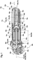
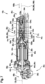
- FIG. 1 a side view of a machine tool 10a is shown, wherein the machine tool 10a is shown cut along a plane through a longitudinal axis 12a of the machine tool 10a.
- the machine tool 10a is designed as a hand-held machine tool.
- the machine tool 10a is designed as an electric machine tool.
- the machine tool 10a is designed as an angle grinder.
- other designs of the machine tool 10a are also conceivable, for example as a drill, as a screwdriver, as a hammer, as a vacuum cleaner or the like.
- the machine tool 10a has a housing unit 14a.
- the machine tool 10a has a drive unit 16a arranged within the housing unit 14a, which is designed in particular as a brushless DC motor.
- the machine tool 10a comprises an electronic device 17a.
- the machine tool 10a has an electronic unit 18a, which is provided at least for controlling and supplying electricity to the drive unit 16a and is designed in particular as part of the electronic device 17a. It is also conceivable that the electronic unit 18a is provided for controlling and/or supplying other components of the machine tool 10a, such as display elements, interfaces or the like.
- the electronic unit 18a is provided for commutation of the drive unit 16a.
- the electronic unit 18a comprises a circuit board 20a, on which in particular a processor unit and a memory unit are arranged, which in particular are in the Figure 1 are not shown.
- the machine tool 10a has a separation unit 22a, which is provided to divide at least one fluid flow 24a conducted through the housing unit 14a, in particular depending on a foreign body density, into at least two partial flows 26a, 28a, wherein a partial flow 26a of the partial flows 26a, 28a has a higher foreign body density compared to another partial flow 28a of the partial flows 26a, 28a.
- the machine tool 10a has a fluid cooling unit 30a, which is provided to cool the drive unit 16a by means of the at least two partial flows 26a, 28a.
- the fluid cooling unit 30a is part of the electronic device 17a.
- the fluid cooling unit 30a is provided for cooling the electronic unit 18a by means of a fluid or the fluid flow 24a.
- the electronic unit 18a is arranged at least largely, in particular completely, outside a fluid flow path 32a of the fluid cooling unit 30a.
- the fluid cooling unit 30a is provided for cooling the drive unit 16a and the electronic unit 18a.
- the fluid cooling unit 30a is provided for guiding the fluid or the fluid flow 24a through the housing unit 14a.
- the fluid cooling unit 30a comprises an intake opening 34a for sucking in the fluid or the fluid flow 24a.
- the intake opening 34a is delimited by the housing unit 14a and is arranged on a side of the machine tool 10a, in particular the housing unit 14a, facing away from a processing area 38a of the machine tool 10a.
- the intake opening 34a is formed along the longitudinal axis 12a of the machine tool 10a, in particular on an end region 40a of the machine tool 10a formed along the longitudinal axis 12a of the machine tool 10a and at least partially facing away from the processing area 38a.
- the fluid cooling unit 30a comprises a plurality of outlet openings 42a, 44a, 46a for draining the fluid or the fluid flow 24a from the machine tool 10a.
- the outlet openings 42a, 44a, 46a are arranged in an end region 48a of the machine tool 10a facing away from the intake opening 34a.
- the outlet openings 42a, 44a, 46a are arranged in an area around a tool holder 50a of the machine tool 10a.
- One outlet opening 42a of the plurality of outlet openings 42a, 44a, 46a is arranged on a side of the machine tool 10a, in particular the housing unit 14a, facing away from the processing area 38a.
- Two outlet openings 44a, 46a of the plurality of outlet openings 42a, 44a, 46a are arranged on a side of the machine tool 10a, in particular the housing unit 14a, facing towards the processing area 38a.
- One outlet opening 44a of the two outlet openings 44a, 46a is provided for discharging the partial flow 26a.
- Another outlet opening 46a of the two outlet openings 44a, 46a is provided for discharging the other partial flow 28a.
- the drive unit 16a has a drive axis 52a about which a rotor of the drive unit 16a is driven.
- the drive axis 52a of the drive unit 16a is aligned at least substantially parallel to the longitudinal axis 12a of the machine tool 10a.
- the drive axis 52a of the drive unit 16a is aligned coaxially to a main extension direction 54a of the fluid cooling unit 30a.
- the fluid cooling unit 30a comprises a channel element, in particular a fluid cooling element 66a, wherein the fluid flow path 32a, in particular in an area in which the electronic unit 18a is arranged, runs at least largely through the channel element.
- the fluid flow path 32a extends from the intake opening 34a of the fluid cooling unit 30a to the outlet openings 42a, 44a, 46a of the fluid cooling unit 30a.
- the fluid cooling unit 30a has a guide path 58a along which the fluid flow path 32a is formed.
- the guide path 58a is formed along a main extension direction 54a of the fluid flow path 32a.
- the electronics unit 18a is arranged at least largely, in particular completely, outside a flow recess 60a enclosed by the fluid cooling unit 30a for conducting the fluid or the fluid flow 24a.
- the fluid cooling unit 30a is designed in such a way and/or the electronics unit 18a is arranged in such a way that the electronics unit 18a, in particular via a channel element, in particular the fluid cooling element 66a, of the fluid cooling unit 30a, is arranged at a distance from the fluid flow path 32a and/or the flow recess 60a enclosed by the fluid cooling unit 30a.
- the fluid cooling unit 30a is provided to guide the fluid flow 24a via the intake opening 34a through the channel element, in particular the fluid cooling element 66a, past the electronics unit 18a and the drive unit 16a to the outlet openings 42a, 44a, 46a.
- the channel element, in particular the fluid cooling element 66a is arranged at least substantially completely within the housing unit 14a.
- the drive unit 16a, the electronics unit 18a and the fluid cooling unit 30a are arranged at least substantially completely within the housing unit 14a, in particular with the exception of the intake opening 34a and/or the outlet openings 42a, 44a, 46a.
- the fluid sucked in via the intake opening 34a or the fluid flow 24a comprises a large number of foreign bodies.
- the Foreign bodies in the fluid flow 24a and/or the partial flows 26a, 28a are formed as dust particles, as residues from a machined workpiece, such as metal chips, as impurities in the fluid flow 24a or the like.
- the fluid or the fluid flow 24a is/is formed at least partially, in particular at least mostly, from air.
- the fluid cooling unit 30a is designed such that when the drive unit 16a is cooled by means of the partial flows 26a, 28a, in particular the partial flow 26a and the further partial flow 28a, heat energy is transferred from the drive unit 16a to the partial flows 26a, 28a.
- the fluid cooling unit 30a is provided to conduct the heat transferred to the partial flows 26a, 28a, in particular the partial flow 26a or the other partial flow 28a, via the partial flows 26a, 28a out of the machine tool 10a, in particular the housing unit 14a.
- the fluid cooling unit 30a is provided to conduct the fluid flow 24a via the intake opening 34a through at least one channel element, in particular the fluid cooling element 66a, of the fluid cooling unit to the separation unit 22a.
- the separation unit 22a and the fluid cooling unit 30a are formed in one piece, wherein in particular the channel element, in particular the fluid cooling element 66a, of the fluid cooling unit 30a is provided to limit the fluid flow 24a on the guide path 58a and/or on partial guide paths 62a, 64a of the partial flow 28a or the other partial flow 28a.
- the fluid cooling unit 30a is provided to guide the partial flows 26a, 28a at least partially in the direction of the drive unit 16a after flowing through the separation unit 22a in order to cool the drive unit 16a.
- the fluid cooling unit 30a comprises the fluid cooling element 66a, against which the electronic unit 18a rests at least partially.
- the electronic unit 18a comprises a heat diffusion element 68a for dissipating heat.
- the heat diffusion element 68a is designed as a copper block and is intended to collect heat generated in particular during operation of the electronic unit 18a and/or to transfer it to the fluid cooling element 66a.
- the electronic unit 18a, in particular the heat diffusion element 68a has at least one support surface 70a (see Figure 4 ).
- the electronic unit 18a, in particular the heat diffusion element 68a rests on the fluid cooling element 66a via the support surface 70a.
- the heat diffusion element 68a is made of a material that has a thermal conductivity of at least 10 W/(m ⁇ K), preferably at least 50 W/(m ⁇ K), preferably at least 100 W/(m ⁇ K), particularly preferably at least 200 W/(m ⁇ K) and very particularly preferably at least 400 W/(m ⁇ K).
- the heat diffusion element 68a is arranged on the circuit board 20a.
- the support surface 70a is designed as a flat surface. However, it is also conceivable that the support surface 70a is at least partially curved.
- the fluid cooling element 66a delimits a fluid channel 72a. The fluid or the fluid flow 24a is guided through the fluid channel 72a or the fluid cooling element 66a past the electronics unit 18a.
- the fluid cooling element 66a is designed such that the fluid channel 72a has a cylindrical shape.
- the fluid cooling element 66a is designed as a channel element for a line of the fluid or the fluid flow 24a, wherein the electronic unit 18a at least partially rests against an outer wall 74a of the fluid cooling element 66a (see Figure 4 ).
- the support surface 70a rests against the outer wall 74a of the fluid cooling element 66a.
- the heat diffusion element 68a rests against the fluid cooling element 66a over its entire surface via a side on which the support surface 70a is arranged.
- the fluid cooling element 66a is made, at least in an area against which the electronic unit 18a rests, from a material that has a thermal conductivity of at least 10 W/(m ⁇ K), preferably at least 50 W/(m ⁇ K), preferably at least 100 W/(m ⁇ K), particularly preferably at least 200 W/(m ⁇ K) and very particularly preferably at least 400 W/(m ⁇ K).
- the fluid cooling element 66a is made of aluminum. However, it is also conceivable that the fluid cooling element 66a is made of another heat-conducting, in particular metallic, material.
- the fluid flow path 32a extends in a close region 76a of the electronic unit 18a at least substantially completely within the fluid cooling element 66a.
- the fluid cooling element 66a is provided to guide, in particular in the close region 76a of the electronic unit 18a, an entire fluid flow 24a, which flows in particular via the intake opening 34a into the fluid cooling unit 30a.
- the fluid flow path 32a runs, in particular in the close region 76a of the electronic unit 18a, at least substantially completely through the fluid cooling element 66a, in particular the fluid channel 72a.
- the fluid cooling element 66a at least, in particular precisely, two fluid channels 72a are delimited, wherein the fluid flow path 32a, in particular in the near region 76a of the electronics unit 18a, runs at least substantially completely through the fluid cooling element 66a, in particular the fluid channels 72a.
- the near region 76a of the electronics unit 18a extends along the main extension direction 54a of the fluid cooling unit 30a, in particular of the fluid cooling element 66a, at least over a complete length 78a of the electronics unit 18a.
- the drive unit 16a is arranged behind the electronics unit 18a and the fluid cooling element 66a, as viewed from the intake opening 34a, in particular in terms of fluid technology.
- the separation unit 22a is arranged behind the electronics unit 18a and the fluid cooling element 66a, as viewed from the intake opening 34a, in particular in terms of fluid technology, and in front of the drive unit 16a.
- the separation unit 22a comprises a separation element 80a designed as a channel element, which is arranged in a close area 82a of the drive unit 16a and is intended to divide the fluid flow 24a.
- the separation element 80a is intended to guide the fluid flow 24a on the guide path 58a and to divide it into the partial flow 26a and the other partial flow 28a.
- the separation element 80a is designed as a passive element, wherein in particular the separation element 80a is intended to divide the fluid flow 24a via a shape of the separation element 80a, in particular when the fluid flow 24a flows through.
- the separation element 80a is designed to be static or immobile.
- the separation element 80a is described in the description of Figure 2 described in detail.
- the separation unit 22a in particular the separation element 80a, is fluidically formed between the intake opening 34a and the drive unit 16a.
- the separation element 80a arranged in the vicinity 82a of the drive unit 16a is arranged, in particular fastened, directly to the drive unit 16a, in particular to a housing of the drive unit 16a. It is conceivable that the separation element 80a arranged in the vicinity 82a of the drive unit 16a is formed in one piece with the drive unit 16a, in particular the housing of the drive unit 16a.
- a channel element 56a of the fluid cooling unit 30a is provided to guide the partial flow 26a, in particular separately from the other partial flow 28a, at least partially past an outer wall 84a of the drive unit 16a.
- the fluid cooling unit 30a comprises a plurality of channel elements 56a which are provided for conducting the partial flow 26a, wherein in particular the channel elements 56a are arranged distributed around the longitudinal axis 12a around the drive unit 16a.
- the separation unit 22a and the fluid cooling unit 30a are designed such that the partial flow 26a, in particular in an area along the drive unit 16a, is conducted through the housing unit 14a at least largely separately from the other partial flow 28a.
- the fluid cooling unit 30a is provided to conduct the other partial flow 28a into or through the drive unit 16a for cooling the drive unit 16a.
- the channel element 56a is arranged outside the drive unit 16a on the outer wall 84a of the drive unit 16a.
- the channel element 56a is arranged directly on the drive unit 16a, in particular the outer wall 84a of the drive unit 16a.
- the channel element 56a lies flat against the outer wall 84a of the drive unit 16a.
- the channel element 56a is intended to transfer heat from the drive unit 16a, in particular the outer wall 84a of the drive unit 16a, to the partial flow 26a, wherein in particular the drive unit 16a is cooled by the partial flow 26a.
- the channel element 56a extends along an entire length 86a of the drive unit 16a on the outer wall 84a of the drive unit 16a.
- the channel element 56a is at least largely made of a heat-conducting material which in particular has a thermal conductivity of in particular at least 10 W/(m ⁇ K), preferably at least 40 W/(m ⁇ K), preferably at least 100 W/(m ⁇ K) and particularly preferably at least 200 W/(m ⁇ K).
- the channel element 56a is at least substantially rectilinear, in particular along an entire length 88a of the outer wall 74a of the drive unit 16a.
- the channel element 56a is at least largely arranged at least substantially parallel to the outer wall 84a of the drive unit 16a, in particular an outer surface of the outer wall 84a of the drive unit 16a, which faces the channel element 56a or at least partially rests against the channel element 56a.
- the separation unit 22a comprises a conveying unit 90a, which is arranged at least partially within the fluid cooling unit 30a and is intended to convey at least the partial flow 26a out of or through the housing unit 14a.
- the conveying unit 90a is designed as a flow pump.
- the conveying unit 90a is intended to suck in the partial flow 26a via the fluid cooling unit 30a, in particular through the intake opening 34a.
- the conveying unit 90a is intended to convey the fluid flow 24a, in particular along the guide section 58a, through the separation unit 22a and, in particular by means of a conveying speed and the separation element 80a, to divide it into the partial flows 26a, 28a, in particular the partial flow 26a and the other partial flow 28a.
- the conveying unit 90a is provided to convey the partial flows 26a, 28a, in particular the partial flow 26a and the other partial flow 28a, in particular after cooling the drive unit 16a, through the outlet openings 42a, 44a, 46a out of the machine tool 10a, in particular the housing unit 14a.
- the conveying unit 90a comprises a conveying element 92a, which is at least partially designed as an axial fan.
- the conveying element 92a is designed as one piece with a fan wheel 94a of the drive unit 16a.
- the conveying element 92a is arranged fluidically behind the drive unit 16a, viewed from the intake opening 34a.
- the conveying unit 90a is provided to convey the partial flow 26a and the other partial flow 28a separately from one another through the housing unit 14a and/or the fluid cooling unit 30a.
- the conveying unit 90a is provided, in particular together with the fluid cooling unit 30a, to convey the partial flows 26a, 28a, in particular after the drive unit 16a, in different directions, which are directed radially outwards in particular from a drive axis 96a of the conveying element 92a.
- the conveying element 92a is arranged, in particular in fluid terms, behind the drive unit 16a, as viewed from the intake opening 34a.
- the conveying element 92a is provided to convey the partial flow 26a, in particular in a close region of the conveying element 92a, in a direction that is at least substantially parallel to the drive axis 96a of the conveying element 92a.
- the conveying element 92a is provided to convey the other partial flow 28a, in particular in a close region of the conveying element 92a, in a direction that is at least substantially perpendicular to the drive axis 96a of the conveying element 92a.
- the conveying unit 90a is provided to convey the partial flow 26a and the other partial flow 28a through differently designed and/or spaced-apart outlet openings 42a, 44a, 46a of the fluid cooling unit 30a from the machine tool 10a or the housing unit 14a.
- the Conveying unit 90a is intended to convey the partial flow 26a through the outlet openings 42a, 44a, 46a.
- Conveying unit 90a is intended to convey the other partial flow 28a through the outlet openings 42a, 44a
- the fluid cooling unit 30a comprises a main channel element 98a for guiding the fluid flow 24a, which is arranged in front of the drive unit 16a when viewed from the intake opening 34a, in particular along the main extension direction 54a of the fluid cooling unit 30a.
- the fluid cooling unit 30a comprises along the main extension direction 54a of the fluid cooling unit 30a in a region of the main channel element 98a only exactly one guide path 58a, which is arranged in particular within the main channel element 98a.
- the guide path 58a extends from the intake opening 34a through the fluid cooling unit 30a to the outlet openings 42a, 44a, 46a.
- the main extension direction 54a of the fluid cooling unit 30a is aligned at least substantially parallel to a main extension direction 102a of the drive unit 16a and/or the housing unit 14a and to the drive axis 96a of the conveying element 92a.
- the main channel element 98a extends from the intake opening 34a, in particular along the main extension direction of the fluid cooling unit 30a, to the separation unit 22a.
- the main channel element 98a is integrally connected to the fluid cooling element 66a.
- the main channel element 98a, the fluid cooling element 66a and the channel element 56a of the fluid cooling unit 30a each have at least substantially smooth inner walls 104a, which in particular delimit the fluid channels 72a carrying the fluid flow 24a.
- the main channel element 98a, the fluid cooling element 66a and the channel element 56a of the fluid cooling unit 30a, in particular the inner walls 104a of the main channel element 98a, the fluid cooling element 66a and the channel element 56a of the fluid cooling unit 30a, are designed to be edge-free, wherein in particular the inner walls 104a of the main channel element 98a, the fluid cooling element 66a and the channel element 56a of the fluid cooling unit 30a continuously merge into one another along a guide direction 106a of the fluid flow 24a.
- the machine tool 10a comprises a sensor unit 108a, which is only shown in outline in the figures.
- the sensor unit 108a comprises at least one sensor element 110a for detecting a temperature the drive unit 16a.
- the electronic unit 18a is preferably provided to control and/or regulate, preferably limit, a performance parameter, for example a maximum speed, of the drive unit 16a depending on the detected temperature in order to avoid overheating of the drive unit 16a or a failure of the machine tool 10a. It is also conceivable that the electronic unit 18a is provided to issue a warning to a user depending on the detected temperature, in particular if a temperature limit is exceeded, for example via an optical, acoustic and/or haptic signal.
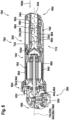
- FIG. 2 a detailed view of the separation element 80a is shown on one side of the longitudinal axis 12a of the machine tool 10a.
- the separation unit 22a is designed such that a value of the foreign body density of the partial flow 26a is greater than a value of the foreign body density of the other partial flow 28a by in particular at least 50%, preferably at least 70%, preferably at least 80% and particularly preferably at least 90%, wherein in particular the foreign bodies have a size, in particular an average diameter, of at least 500 ⁇ m, preferably at least 100 ⁇ m and particularly preferably at least 20 ⁇ m.
- the separation unit 22a is provided to divide the fluid flow 24a into the partial flow 26a and the other partial flow 28a via a geometric design of the guide section 58a of the, in particular sucked in, fluid flow 24a, wherein the partial flow 26a in particular has a higher foreign body density compared to the other partial flow 28a.
- the separation unit 22a is provided to guide the partial flow 26a and the other partial flow 28a, in particular from the guide section 58a to the various partial guide sections 62a, 64a.
- the separating element 80a forms a fluid inlet 112a for conducting the fluid flow 24a and two fluid outlets 114a, 116a for conducting the partial flow 26a or the other partial flow 28a.
- the separating element 80a has in a sectional plane comprising the guide path 58a and/or at least one of the partial guide paths 62a, 64a, which in particular corresponds to an image plane of the Figure 2 corresponds, has an at least partially curved basic shape.
- the separating element 80a is designed such that the guide path 58a in a region of the fluid inlet 114a to the partial guide path 64a of the other partial flow 28a in a region of the fluid outlet 114a has an angle 118a of in particular at least 30°, preferably at least 60° and particularly preferably at least 80°.
- the separation element 80a has a basic shape which is designed such that foreign bodies are guided onto a path deviating from the guide path 58a of the fluid flow 24a, in particular the partial guide path 64a of the other partial flow 28a, in particular onto the partial guide path 62a of the partial flow 26a.
- the separation element 80a is designed such that the partial flow 26a is guided at least partially separately from the other partial flow 28a.
- the separation element 80a is arranged on the fluid cooling unit 30a or is designed as part of the fluid cooling unit 30a.
- the separating element 80a is formed integrally with the fluid cooling unit 30a, in particular at least one channel element 56a of the fluid cooling unit 30a, which in Figure 2 but is not shown.
- the separation unit 22a, in particular the separation element 80a, is fluidically formed between the suction opening 34a and the drive unit 16a.
- foreign bodies within the fluid flow 24a are moved by their inertia on a path that depends on a mass of the foreign bodies.
- foreign bodies with a larger mass fly on a less curved path than foreign bodies with a smaller mass.
- foreign bodies with a large mass are guided to a fluid outlet 116a of the fluid outlets 114a, 116a, which is provided for guiding the partial flow 26a.
- Another fluid outlet 114a of the fluid outlets 112a, 114a is provided for guiding the other partial flow 28a.
- the guide path 58a in the region of the fluid inlet 112a has a smaller angle to the partial guide path 62a of the partial flow 26a in the region of the fluid outlet 116a than to the partial guide path 64a of the other partial flow 28a in the region of the other fluid outlet 114a.
- the separating element 80a is designed such that a swirl of the fluid or the fluid flow forms on an inner wall 122a of the separating element 80a delimiting the partial guide path 62a of the partial flow 26a.
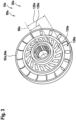
- FIG 3 a perspective view of the conveying element 92a is shown.
- the conveying element 92a of the conveying unit 90a is designed as a radial fan in at least one area 124a of the conveying element 92a.
- the conveying element 92a is designed as an axial fan in at least one further area 126a of the conveying element 92a.
- the area 124a of the conveying element 92a is enclosed by the further area 126a when viewed along the drive axis 96a of the conveying element 92a.
- the area 124a of the conveying element 92a has a smaller minimum radial distance 128a to the drive axis 96a of the conveying element 92a than the further area 126a of the conveying element 92a (cf. distance 129a).
- the conveying element 92a is designed as a two-part fan wheel.
- the region 124a of the conveying element 92a is intended for conveying the other partial flow 28a through the drive unit 16a.
- the further region 126a of the conveying element 92a is intended for conveying the partial flow 26a through the channel element 56a or along the outer wall 74a of the drive unit 16a.
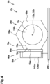
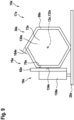
- FIG 4 a schematic cross section of the electronic device 17a is shown in the near area 76a of the electronic unit 18a.
- the electronic unit 18a is arranged directly on the fluid cooling element 66a.
- the electronic unit 18a rests at least partially on the outer wall 74a of the fluid cooling element 66a.
- the fluid cooling element 66a delimits the fluid channel 72a to a line of the fluid, which has an at least substantially round cross-sectional area 130a.
- the cross-sectional area 130a of the fluid channel 72a is aligned at least substantially perpendicular to a central axis 132a of the fluid cooling element 66a.
- the cross-sectional area 130a of the fluid channel 72a is aligned at least substantially perpendicular to the support surface 70a and/or the outer wall 74a of the fluid cooling element 66a.
- the cross-sectional area 130a of the fluid channel 72a has a contour that is at least substantially circular.
- a maximum value of the cross-sectional area 130a of the fluid channel 72a delimited by the fluid cooling element 66a is at least 100 mm 2 , preferably at least 200 mm 2 , preferably at least 400 mm 2 and particularly preferably at least 600 mm 2 .
- the fluid cooling element 66a has at least one contact surface 134a on the outer wall 74a of the fluid cooling element 66a, which at least substantially corresponds to the support surface 70a of the electronics unit 18a, wherein the electronics unit 18a rests on the contact surface 134a of the fluid cooling element 66a via the contact surface 70a.
- the contact surface 134a and the contact surface 70a are designed as flat surfaces. However, it is also conceivable that the contact surface 134a and the contact surface 70a are designed as at least partially curved surfaces.
- the electronics unit 18a in particular an electronic component 136a of the electronics unit 18a, is fastened, for example glued and/or screwed, to the fluid cooling element 66a, in particular the contact surface 134a, via the contact surface 70a.
- the contact surface 134a and the contact surface 70a have a maximum area of at least 100 mm 2 , preferably at least 200 mm 2 , preferably at least 400 mm 2 and particularly preferably at least 600 mm 2 .
- the contact surface 134a and/or the support surface 70a preferably have/have a maximum area of at most 5000 mm 2 , preferably at most 3000 mm 2 and particularly preferably at most 2000 mm 2 .
- the support surface 70a is arranged completely on the heat diffusion element 68a.
- the fluid cooling element 66a has a hexagonal basic shape 138a, wherein the contact surface 134a is formed as one side of the basic shape 138a.
- the heat diffusion element 68a is arranged on the electronic component 136a of the electronic unit 18a and is intended to dissipate heat generated by the electronic component 136a to the fluid cooling element 66a.
- the electronic component 136a is designed as a power semiconductor, such as an IGBT or a MOSFET. It is also conceivable that, alternatively or additionally, a processor unit, a memory unit or the like is arranged on the heat diffusion element 68a for cooling.
- the electronic component 136a is attached to the circuit board 20a of the electronic unit 18a. Other configurations of the electronic unit 18a, in particular of the heat diffusion element 68a, are also conceivable.
- the electronic device 17a comprises a sealing unit 140a, which is intended to seal the electronic unit 18a together with the fluid cooling unit 30a at least partially, in particular with respect to the fluid flow path 32a, at least substantially airtight and/or watertight.
- the sealing unit 140a has a sealing element 142a, which is made of a heat-insulating material, in particular rubber.
- the sealing element 142a lies at least partially on the heat diffusion element 68a. It is also conceivable that the sealing element 142a completely encloses the heat diffusion element 68a together with the fluid cooling element 66a.
- the sealing element 142a is made of a thermally conductive material which in particular has a thermal conductivity of at least 10 W/(m ⁇ K), preferably at least 50 W/(m ⁇ K), preferably at least 100 W/(m ⁇ K), particularly preferably at least 200 W/(m ⁇ K) and very particularly preferably at least 400 W/(m ⁇ K).
- the sealing element 142a at least substantially completely encloses the electronic component 136a of the electronic unit 18a together with the fluid cooling element 66a and the heat diffusion element 68a.
- a volume enclosed between the sealing element 142a and the electronics unit 18a or the fluid cooling element 66a and/or the heat diffusion element 68a is filled with a heat-insulating gas or evacuated.
- the evacuated volume has a maximum pressure of in particular less than 1000 mbar, preferably less than 300 mbar, preferably less than 1 mbar and particularly preferably less than 10 -2 mbar.
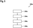
- FIG. 5 an exemplary sequence of a method 200a for cooling the drive unit 16a or the electronics unit 18a of the machine tool 10a is shown.
- a method step 202a of the method 200a the fluid flow 24a is sucked through the intake opening 34a by means of the conveying unit 90a.
- the electronics unit 18a is cooled by means of the fluid flow 24a flowing through the main channel element 98a via the fluid cooling element 66a.
- the fluid flow 24a flows through the fluid cooling element 66a, whereby heat is released from the electronics unit 18a to the fluid flow 24a via the fluid cooling element 66a in order to cool the electronics unit 18a.
- the fluid flow 24a is divided into the partial flow 26a, which is particularly loaded with foreign bodies, and the other partial flow 28a, which is particularly low in foreign bodies, by means of the separation unit 22a, in particular the separation element 80a.
- the partial flow 26a is guided by means of the separation unit 22a and the fluid cooling unit 30a through the channel element 56a along the outer wall 84a of the drive unit 16a, wherein the drive unit 16a is the partial flow 26a is cooled, in particular heat is transferred from the outer wall 84a of the drive unit 16a to the partial flow 26a.
- the other partial flow 28a is guided into or through the drive unit 16a by means of the separation unit 22a and the fluid cooling unit 30a, wherein the drive unit 16a, in particular windings of the drive unit 16a, are cooled by means of the other partial flow 28a, in particular wherein heat is transferred from the drive unit 16a to the other partial flow 28a.
- the other partial flow 28a is conveyed via the region 124a of the conveying element 92a in a direction facing the processing region 38a or the outlet opening 46a and conveyed through the outlet opening 46a out of the machine tool 10a, in particular the housing unit 14a and/or the fluid cooling unit 30a.
- the partial flow 26a is conveyed via the further region 126a of the conveying element 92a in directions aligned at least substantially parallel to the drive axis 96a of the conveying element 92a and guided via the fluid cooling unit 30a to the outlet openings 42a, 44a or out of the machine tool 10a, in particular the housing unit 14a and/or the fluid cooling unit 30a.
- FIG 6 an alternative embodiment of a separating unit 22b, in particular a separating element 80b, or a conveyor unit 90b of a machine tool 10b is shown.
- the machine tool 10b has a housing unit 14b, a drive unit arranged within the housing unit 14b 16b, which is particularly relevant in the Figure 6 not shown, and the separation unit 22b, wherein the separation unit 22b is provided to divide at least one fluid flow 24b guided through the housing unit 14b, in particular depending on a foreign body density, into at least two partial flows 26b, 28b, wherein a partial flow 26b of the partial flows 26b, 28b has a higher foreign body density compared to another partial flow 28b of the partial flows 26b, 28b.
- the machine tool 10b has a fluid cooling unit 30b, which is provided to cool the drive unit 16b by means of the at least two partial flows 26b, 28b.
- the Figure 6 The machine tool 10b shown has an at least substantially analogous design to that described in the description of the Figures 1 to 5 described machine tool 10a, so that with regard to a design of the machine tool 10a Figure 6 illustrated machine tool 10b at least essentially to the description of the Figures 1 to 5 In contrast to the description of the Figures 1 to 5
- the machine tool 10a described in the drawing has the separating unit 22b and/or the conveying unit 90b of the Figure 6
- the machine tool 10b shown preferably has a further conveying element 144b.
- the further conveying element 144b is arranged at a fluid outlet 114b of the separating element 80b, which is provided for guiding the fluid flow 24b.
- the further conveying element 144b is designed as a fan.
- the further conveying element 144b is provided for conveying the partial flow 26b into a channel element 56b of the fluid cooling unit 30b, which is arranged along an outer wall 84b of the drive unit 16b, which is in particular in the Figure 6 is not shown, and is intended to cool the drive unit 16b via the partial flow 26b.
- the further conveying element 144b is intended to draw foreign bodies in the fluid flow 24b into the partial flow 26b, wherein in particular a foreign body density of the partial flow 26b is increased and a foreign body density of the other partial flow 28b is reduced.
- the further conveying element 144b is arranged, in particular fluidically, between the intake opening 34b of the fluid cooling unit 30b and the drive unit 16b.
- the further conveying element 144b is arranged at least largely within the fluid cooling unit 30b, in particular the channel element 56b.
- the further conveying element 144b is arranged, in particular fluidically, between the separation unit 22b and the drive unit 22b or outlet openings 42b, 44b, 46b of the fluid cooling unit 30b.
- the further conveying element 144b is arranged between an intake opening 36b of the fluid cooling unit 30b and the separation element 80b.
- the further conveying element 144b is intended to convey the partial flow 26b and/or the other partial flow 28b through the fluid cooling unit 30b, through the separation unit 22b and/or out of the machine tool 10b or the housing unit 14b.
- the partial flow 26b and the other partial flow 28b are guided together through several outlet openings 42b, 44b, 46b out of the machine tool 10b after flowing through or past the drive unit 16b.
- the partial flow 26b and the other partial flow 28b are brought together within the machine tool 10b, in particular the housing unit 14b, after flowing through or past the drive unit 16b in a channel element of the fluid cooling unit 30b.
- the fluid cooling unit 30b is designed such that the partial flow 26b and the other partial flow 28b are guided separately out of the machine tool 10b.
- FIG 7 an alternative embodiment of a machine tool 10c is shown, in particular in an analogous manner to Figure 1
- the machine tool 10c has an electronic device 17c, a housing unit 14c, a drive unit 16c arranged within the housing unit 14c and a separation unit 22c, wherein the separation unit 22c is provided to divide at least one fluid flow 24c conducted through the housing unit 14c, in particular depending on a foreign body density, into at least two partial flows 26c, 28c, wherein a partial flow 26c of the partial flows 26c, 28c has a higher foreign body density compared to another partial flow 28c of the partial flows 26c, 28c.
- the machine tool 10c or the electronic device 17c has/has a fluid cooling unit 30c which is provided to cool the drive unit 16c by means of the at least two partial flows 26c, 28c.
- the machine tool 10c or the electronic device 17c comprise/comprises an electronic unit 18c, wherein the fluid cooling unit 30c is provided to cool the electronic unit 18c by means of a fluid or the fluid flow 24c.
- the electronic unit 18c is arranged at least largely, in particular completely, outside a fluid flow path 32c of the fluid cooling unit 30c.
- the machine tool 10c, in particular the separation unit 22c has a conveying unit 90c for conveying the fluid through the fluid cooling unit 30c.
- the machine tool 10c shown has an at least substantially analogous design to that described in the description of the Figures 1 to 5 described machine tool 10a, so that with regard to a design of the machine tool 10a Figure 7
- the machine tool 10c shown at least essentially refers to the description of the Figures 1 to 5
- the machine tool 10a described in the drawing has the separating unit 22c of the Figure 7
- the machine tool 10c shown preferably has a further separation element 93c, which is arranged within a main channel element 98c of the fluid cooling unit 30c and is intended to guide the fluid flow 24c to a division of the partial flows 26c, 28c along the main channel element 98c onto a circular path 174c.
- the further separation element 93c is designed as a helical molded part.
- the further separation element 93c delimits, in particular within and/or together with the main channel element 98c, a fluid guide channel which extends from the intake opening 34c in the direction of the drive unit 16c along a curve which runs with a constant gradient around a lateral surface of an imaginary cylinder.
- the curve forms the circular path 174c in a projection plane.
- the conveying unit 90c of the machine tool 10c comprises a conveying element 92c, which is formed in one piece with a fan of the drive unit 16c.
- the conveying element 92c is arranged behind the main channel element 98c, the further separation element 93c and the drive unit 16c, as viewed from an intake opening 34c of the fluid cooling unit 30c.
- the conveying element 92c is provided to suck the fluid flow 24c through the intake opening 34c into the machine tool 10c, in particular the fluid cooling unit 30c.
- the conveying element 92c is provided to convey the fluid flow 24c through the main channel element 98c and a fluid channel delimited by the main channel element 98c and the further separation element 93c and in particular to convey the partial flow 26c through the channel element 56c after the separation unit 22c.
- a separating element 80c of the separating unit 22c and the fluid cooling unit 30c are designed such that the partial flow 26c and the other partial flow 28c are guided separately from one another after exiting the further separating element 93c.
- the separating element 80c is designed as a Funnel, wherein in particular the other partial flow 28c is guided along a central axis 146c of the separating element 80c, which is arranged in particular coaxially to a central axis of the further separating element 93c and the main channel element 98c, and the partial flow 28c is guided along an outer wall 148c of the separating element 80c.
- the separating element 80c is at least partially conical.
- the separating element 80c delimits at least one passage 150c around the central axis 146c, which is provided in particular for guiding the other partial flow 28c, in particular through or into the drive unit 16c.
- the conveying element 92c is provided to divide the fluid flow 24c together with a separation element 80c of the separation unit 22c into the partial flows 26c, 28c, wherein in particular the partial flow 26c has a greater radial distance from the center axis of the further separation element 93c and the main channel element 98c than the other partial flow 28c.
- the further separation element 93c is at least largely enclosed by the main channel element 98c when viewed along its center axis.
- the further separation element 98c is provided to compress the fluid on an inner wall 152c of the fluid cooling element 66c or the main channel element 98c, which inner wall delimits a fluid channel 72c, in particular for cooling the electronics unit 18c.
- the further separation element 98c is provided to increase a flow duration of the fluid or the fluid stream 24c through the fluid cooling element 66c or the main channel element 98c, in particular in comparison to an embodiment wherein the fluid cooling element 66c or the main channel element 98c is hollow, in particular without the further separation element 93c.
- the separation unit 22c or the fluid cooling unit 30c comprise a filter element 154c, which is intended to change, in particular to reduce, the foreign body density of the fluid flow 24c.
- the filter element 154c is arranged, in particular directly, on the intake opening 34c of the fluid cooling unit 30c.
- the filter element 154c in particular a filter surface 156c of the filter element 154c, is arranged at least partially transversely to a main extension direction 54c of the fluid cooling unit 30c.
- the filter surface 156c spans the main extension direction 54c of the fluid cooling unit 30c in a region of the filter element 154c or the intake opening 34c has an angle 158c which has a value from a range of values of in particular 8° to 82°, preferably 10° to 50° and particularly preferably 15° to 30°.
- the angle 158c spanned by the filter surface 156c and the main extension direction 54c of the fluid cooling unit 30c is preferably at least substantially 18°.
- the filter element 154c is at least largely conical.
- the design of the filter element 154c can preferably achieve a low flow resistance of the filter element 154c in the fluid flow 24c.
- the fluid flow 24c is conveyed out of the machine tool 10c by means of the conveying element 92c via a plurality of outlet openings 42c, 44c, 46c.
- the filter element 154c is arranged on the separation element 80c and is provided for filtering, in particular reducing a foreign body density, the other partial flow 28c before it enters the drive unit 16c.
- the partial flow 26c and the other partial flow 28c are brought together within the machine tool 10c, in particular the housing unit 14c, after flowing through or past the drive unit 16c in a further channel element 160c of the fluid cooling unit 30c.
- the fluid cooling unit 30c is designed such that the partial flow 26c and the other partial flow 28c are guided separately out of the machine tool 10c.
- the conveyor unit 90c has a further conveyor element designed as a spiral wheel, which in particular in the Figure 7 is not shown or that the further separation element 93c is designed to be movable by means of a drive element of the drive unit 16c, in particular about its central axis.
- the drive element is provided to drive the further separation element 93c and thereby convey the fluid flow 24c through the fluid cooling unit 30c, in particular the main channel element 98c.
- FIG 8 an alternative embodiment of a machine tool 10d is shown, in particular in an analogous manner to Figure 1
- the machine tool 10d has an electronic device 17d, a housing unit 14d and a drive unit 16d arranged within the housing unit 14d.
- the machine tool 10d or the electronic device 17d has a fluid cooling unit 30d which is provided to cool the drive unit 16d by means of the at least two partial flows 26d, 28d.
- the machine tool 10d or the electronic device 17d comprises an electronic unit 18d, wherein the fluid cooling unit 30d is provided to cool the electronic unit 18d by means of a fluid or the fluid flow 24d.
- the electronic unit 18d is arranged at least largely, in particular completely, outside of a fluid flow path 32d of the fluid cooling unit 30d.
- the machine tool 10d shown has an at least substantially analogous design to that described in the description of the Figures 1 to 5 described machine tool 10a, so that with regard to a design of the machine tool 10a Figure 8 illustrated machine tool 10d at least essentially to the description of the Figures 1 to 5 In contrast to the description of the Figures 1 to 5
- the machine tool 10a described in the Figure 8 The machine tool 10d shown preferably does not have a separation unit.
- the fluid cooling unit 30d is provided to cool the electronics unit 18d and the drive unit 16d by means of the sucked-in fluid flow 24d, wherein in particular the drive unit 16d is cooled by guiding the fluid flow 24d along an outer wall 84d of the drive unit 16d.
- the fluid cooling unit 30d comprises a channel element 56d which guides the fluid flow 24d directly along and at least substantially parallel to the outer wall 84d of the drive unit 16d.
- the fluid flow 24d is conveyed through the machine tool 10d via a conveying unit 90d.
- the conveying unit 90d comprises a conveying element 92d which, in particular in terms of fluid technology, is arranged behind the drive unit 16d as viewed from the suction opening 34d.
- the fluid cooling unit 30d comprises a fluid cooling element 66d, which is intended to dissipate heat from the electronics unit 18d to the fluid flow 24d.
- the fluid cooling element 66d is formed in one piece with a main channel element 98d of the fluid cooling unit 30d, wherein in particular an entire sucked-in fluid flow 24d runs in a close region 76d of the electronics unit 18d through the main channel element 98d and the fluid cooling element 66d.
- the fluid cooling unit 30d comprises a deflection element 162d, which in particular is formed at least substantially conically.
- the deflection element 162d is designed to be streamlined.
- the deflection element 162d is provided to guide the fluid flow 24d from the main channel element 98d into the channel element 56d, wherein in particular the fluid flow 24d is guided radially outward from a central axis 146d of the main channel element 98d.
- FIG 9 an alternative embodiment of a fluid cooling element 66e of a fluid cooling unit 30e of a machine tool 10e or an electronic device 17e is shown.
- the Figure 9 The machine tool 10e or electronic device 17e shown has an at least substantially analogous design to that described in the description of the Figures 1 to 5 described machine tool 10a or electronic device 17a, so that with regard to an embodiment of the described Figure 9 illustrated machine tool 10e or electronic device 17e at least essentially to the description of the Figures 1 to 5
- the machine tool 10e or electronic device 17e shown preferably has a fluid channel 72e which has a square cross-sectional area 130e.
- the cross-sectional area 130e of the fluid channel 72e delimited by the fluid cooling element 66e is hexagonal.
- a minimum wall thickness 164e of the fluid cooling element 66e is in particular at least 0.5 mm, preferably at least 1 mm, preferably at least 1.5 mm and particularly preferably at least 2 mm, and/or in particular at most 10 mm, preferably at most 6 mm and preferably at most 4 mm.
- a maximum value of the cross-sectional area 130e of the fluid channel 72e delimited by the fluid cooling element 66e is preferably at least 100 mm 2 , preferably at least 200 mm 2 , preferably at least 400 mm 2 and particularly preferably at least 600 mm 2 .
- an electronics unit 18e of the machine tool 10e is designed without a sealing unit.
- other configurations of the fluid cooling unit 30e and/or the electronics unit 18e are also conceivable.
- FIG 10 another alternative embodiment of a machine tool 10f or an electronic device 17f is shown, wherein the machine tool 10f analogous to Figure 1 shown in a longitudinal section.
- the Figure 10 The machine tool 10f shown has an at least substantially analogous design to that described in the description of the Figure 8 described machine tool 10d, so that with regard to a design of the machine tool described in Figure 10
- the machine tool 10f shown at least essentially refers to the description of the Figure 8
- the machine tool 10f shown has more than one suction opening 34f, 36f for sucking in a fluid or a fluid flow 24f for cooling an electronics unit 18f and a drive unit 16f by means of a fluid cooling unit 30f.
- the suction openings 34f, 36f are provided for guiding fluid or the fluid flow 24f into a main channel element 98f of the fluid cooling unit 30f.
- the housing unit 14f and/or the fluid cooling unit 30f delimit ten intake openings 34f, 36f, wherein four intake openings 34f of the ten intake openings 34f, 36f are arranged on an outer wall 168f of the machine tool 10f, in particular the housing unit 14f, which is aligned at least substantially perpendicular to a central axis 166f of the main channel element 98f or to a longitudinal axis 12f of the machine tool 10f.
- Three intake openings 36f of the ten intake openings 34f, 36f are arranged on mutually opposite outer walls 170f of the machine tool 10f, in particular the housing unit 14f, which are aligned at least substantially parallel to the central axis 166f of the main channel element 98f or to the longitudinal axis 12f of the machine tool 10f.
- the ten intake openings 34f, 36f are provided to receive the fluid or the fluid flow 24f on a side of the machine tool 10f facing away from a processing area 38f of the machine tool 10f and to bundle it in the main channel element 98f, in particular before it flows through a fluid cooling element 66f of the fluid cooling unit 30f.
- housing unit 14f and/or the fluid cooling unit 30f are also conceivable, in particular with a number of intake openings 34f, 36f that differs from ten. It is conceivable that a filter element is attached to the intake openings 34f, 36f, in particular in each case, to reduce the density of foreign bodies in the intake fluid flow 24f.
- FIG 11 another alternative embodiment of a machine tool 10g or an electronic device 17g is shown, wherein the machine tool 10g is analogous to the Figure 1 shown in a longitudinal section.
- the Figure 11 The machine tool 10g shown has an at least substantially analogous design to that described in the description of the Figure 8 described machine tool 10d, so that with regard to a design of the machine tool described in Figure 11
- the machine tool 10g shown at least essentially refers to the description of the Figure 8
- the machine tool 10g shown has more than one intake opening 36g for sucking in a fluid or a fluid flow 24g for cooling an electronics unit 18g and a drive unit 16g by means of a fluid cooling unit 30g.
- the intake openings 36g are provided for guiding fluid or the fluid flow 24g into a main channel element 98g of the fluid cooling unit 30g.
- the housing unit 14g and/or the fluid cooling unit 30g delimit six intake openings 36g, wherein three intake openings 36g of the six intake openings 36g are arranged on mutually facing outer walls 170g of the machine tool 10g, in particular the housing unit 14g, which are in particular aligned at least substantially parallel to a central axis 166g of the main channel element 98g or to a longitudinal axis 12g of the machine tool 10g.
- the six intake openings 36g are provided to receive the fluid or the fluid flow 24g on a side of the machine tool 10g facing away from a processing area 38g of the machine tool 10g and to bundle it in the main channel element 98g, in particular before it flows through a fluid cooling element 66g of the fluid cooling unit 30g.
- the machine tool 10g is designed as a battery-operated machine tool.
- a battery pack 172g is attached to an outer wall 168g of the machine tool 10g, in particular the housing unit 14g, which is aligned at least substantially perpendicular to the central axis 166g of the main channel element 98g or to the longitudinal axis 12g of the machine tool 10g.
- the intake openings 36g are aligned away from the battery pack 172g.
- other configurations of the housing unit 14g and/or the fluid cooling unit 30g are also conceivable. in particular with a number of intake openings other than six 36g.
Landscapes
- Engineering & Computer Science (AREA)
- Mechanical Engineering (AREA)
- Auxiliary Devices For Machine Tools (AREA)
- Cooling Or The Like Of Semiconductors Or Solid State Devices (AREA)
Description
- Es ist bereits eine Werkzeugmaschine mit zumindest einer Gehäuseeinheit, mit zumindest einer innerhalb der Gehäuseeinheit angeordneten Antriebseinheit und mit zumindest einer Abscheideeinheit vorgeschlagen worden, wobei die Abscheideeinheit dazu vorgesehen ist, zumindest einen durch die Gehäuseeinheit geleiteten Fluidstrom in zumindest zwei Teilströme zu teilen, wobei ein Teilstrom der Teilströme im Vergleich zu einem anderen Teilstrom der Teilströme eine höhere Fremdkörperdichte aufweist.
-
EP 3 549 717 A1 offenbart den Oberbegriff des Anspruches 1. - Andere Beispiele von Werkzeugmaschinen sind aus der
JP S58 49066 A WO 2016/002542 A1 ,DE 21 2013 000108 U1 oderDE 10 2008 041370 A1 bekannt. - Die Erfindung geht aus von einer Werkzeugmaschine, insbesondere einer handgeführten Werkzeugmaschine, nach Anspruch 1.
- Unter "vorgesehen" soll insbesondere speziell programmiert, speziell ausgelegt und/oder speziell ausgestattet verstanden werden. Darunter, dass ein Objekt, insbesondere die Fluidkühlungseinheit, zu einer bestimmten Funktion, insbesondere die Antriebseinheit mittels der zumindest zwei Teilströme zu kühlen, vorgesehen ist, soll insbesondere verstanden werden, dass das Objekt diese bestimmte Funktion in zumindest einem Anwendungs- und/oder Betriebszustand erfüllt und/oder ausführt. Vorzugsweise umfasst der Fluidstrom eine Vielzahl von Fremdkörpern, wobei insbesondere eine Anzahl, ein Volumen und/oder eine Masse von Fremdkörpern pro Volumeneinheit, beispielsweise pro cm3, im Fluidstrom die Fremdkörperdichte angeben. Insbesondere sind die Fremdkörper im Fluidstrom und/oder den Teilströmen als Staubteilchen, als Rückstände von einem bearbeiteten Werkstück, insbesondere Metallspäne, als Verunreinigungen in dem Fluidstrom o. dgl. ausgebildet. Vorzugsweise sind/ist der Fluidstrom und/oder die Teilströme zumindest teilweise, insbesondere zumindest größtenteils, aus Luft ausgebildet. Bevorzugt umfasst die Fluidkühlungseinheit zumindest eine Einsaugöffnung, die insbesondere von der Gehäuseeinheit begrenzt ist. Insbesondere ist die Einsaugöffnung an einer einem Bearbeitungsbereich der Werkzeugmaschine abgewandten Seite der Gehäuseeinheit angeordnet. Bevorzugt umfasst die Fluidkühlungseinheit zumindest eine Auslassöffnung, die von der Gehäuseeinheit zumindest teilweise begrenzt ist und bevorzugt beabstandet von der Einsaugöffnung angeordnet ist. Insbesondere umfasst der Teilstrom und/oder der andere Teilstrom einen von Null verschiedenen Wert für die Fremdkörperdichte. Bevorzugt ist die Fluidkühlungseinheit derart ausgebildet, dass bei einem Kühlen der Antriebseinheit mittels der Teilströme, insbesondere des Teilstroms und/oder des weiteren Teilstroms, Wärmeenergie von der Antriebseinheit auf die Teilströme, insbesondere den Teilstrom beziehungsweise den weiteren Teilstrom, übertragen wird. Bevorzugt ist die Fluidkühlungseinheit dazu vorgesehen, die auf die Teilströme, insbesondere den Teilstrom beziehungsweise den weiteren Teilstrom, übertragene Wärme über die Teilströme, insbesondere den Teilstrom beziehungsweise den weiteren Teilstrom, aus der Werkzeugmaschine, insbesondere der Gehäuseeinheit, zu leiten.
- Bevorzugt ist die Abscheideeinheit derart ausgebildet, dass ein Wert der Fremdkörperdichte des Teilstroms um insbesondere mindestens 50%, vorzugsweise mindestens 70%, bevorzugt mindestens 80% und besonders bevorzugt mindestens 90%, größer ist wie ein Wert der Fremdkörperdichte des anderen Teilstroms, wobei insbesondere die Fremdkörper eine Größe, insbesondere einen mittleren Durchmesser, von mindestens 500 µm, vorzugsweise mindestens 100 µm und besonders bevorzugt mindestens 20 µm, aufweisen. Bevorzugt ist die Abscheideeinheit dazu vorgesehen, den Fluidstrom über eine geometrische Ausbildung einer Führungsstrecke des, insbesondere angesaugten, Fluidstroms in den Teilstrom und den anderen Teilstrom zu teilen, wobei insbesondere der Teilstrom im Vergleich zu dem anderen Teilstrom eine höhere Fremdkörperdichte aufweist. Vorzugsweise ist die Abscheideeinheit dazu vorgesehen, den Teilstrom und den anderen Teilstrom, insbesondere von der Führungsstrecke auf verschiedene Teilführungstrecken zu leiten. Bevorzugt ist die Fluidkühlungseinheit dazu vorgesehen, den Fluidstrom über die Einsaugöffnung durch zumindest ein Kanalelement an die Abscheideeinheit zu leiten. Insbesondere ist das Kanalelement zumindest im Wesentlichen vollständig innerhalb der Gehäuseeinheit angeordnet. Unter "im Wesentlichen vollständig" soll insbesondere eine Angabe eines Anteils eines Bauteils, insbesondere des Kanalelements, welcher eine bestimmte Eigenschaft, insbesondere von der Gehäuseeinheit umschlossen zu sein, aufweist, verstanden werden, wobei insbesondere mindestens 90%, vorzugsweise mindestens 95% und besonders bevorzugt mindestens 98% eines gesamten Volumens und/oder einer gesamten Masse des Bauteils die Eigenschaft aufweist. Bevorzugt sind die Abscheideeinheit und die Fluidkühlungseinheit einstückig ausgebildet, wobei insbesondere ein Kanalelement der Fluidkühlungseinheit dazu vorgesehen ist, den Fluidstrom auf der Führungsstrecke und/oder den Teilführungsstrecken zu begrenzen. Zumindest ist ein Abscheideelement der Abscheideeinheit als ein Kanalelement der Fluidkühlungseinheit ausgebildet und begrenzt insbesondere zumindest einen Fluidkanal zu einer Leitung des Fluids. Unter "einstückig" soll insbesondere stoffschlüssig verbunden, wie beispielsweise durch einen Schweißprozess und/oder Klebeprozess usw., und besonders vorteilhaft angeformt verstanden werden, wie durch die Herstellung aus einem Guss und/oder durch die Herstellung in einem Ein- oder Mehrkomponentenspritzverfahren. Vorzugsweise ist die Fluidkühlungseinheit dazu vorgesehen, die Teilströme nach einem Durchfließen der Abscheideeinheit zu einem Kühlen der Antriebseinheit zumindest teilweise in Richtung der Antriebseinheit zu leiten.
- Vorzugsweise ist die Werkzeugmaschine als eine handgeführte Werkzeugmaschine ausgebildet. Beispielsweise ist die Werkzeugmaschine als ein Winkelschleifer, als ein Bohrer, als ein Sauger, als ein Schrauber o. dgl. ausgebildet. Insbesondere ist die Antriebseinheit als ein Motor, insbesondere ein Elektromotor, ausgebildet. Vorzugsweise sind/ist die Antriebseinheit, die Abscheideeinheit und/oder die Fluidkühlungseinheit, insbesondere mit Ausnahme von der Einsaugöffnung und/oder der Auslassöffnung, zumindest im Wesentlichen vollständig innerhalb der Gehäuseeinheit angeordnet.
- Durch die erfindungsgemäße Ausgestaltung der Werkzeugmaschine kann, insbesondere ohne eine Verschmutzung der Antriebseinheit, eine vorteilhaft effektive Kühlung der Antriebseinheit ermöglicht werden, insbesondere da der Teilstrom und der andere Teilstrom zu einem Kühlen der Antriebseinheit verwendet werden können. Es kann eine vorteilhaft hohe Energieeffizienz bei einem Kühlen der Antriebseinheit erreicht werden, insbesondere da ein angesaugter Fluidstrom vollständig zum Kühlen der Antriebseinheit verwendet werden kann.
- Des Weiteren wird vorgeschlagen, dass die Abscheideeinheit zumindest ein als Kanalelement ausgebildetes Abscheideelement umfasst, das in einem Nahbereich der Antriebseinheit angeordnet ist und dazu vorgesehen ist, den Fluidstrom zu teilen. Es kann eine vorteilhaft effektive Kühlung der Antriebseinheit mittels der Teilströme erreicht werden. Es kann eine vorteilhaft kompakte Bauweise ermöglicht werden, da die Teilströme erst vor einem Vorbeiströmen an der Antriebseinheit geteilt werden können. Insbesondere ist das Abscheideelement dazu vorgesehen, den Fluidstrom auf der Führungsstrecke zu leiten und in den Teilstrom und den anderen Teilstrom zu teilen. Vorzugsweise ist das Abscheideelement als ein passives Element ausgebildet, wobei insbesondere das Abscheideelement dazu vorgesehen ist, den Fluidstrom über eine Form des Abscheideelements, insbesondere bei einem Durchfließen des Fluidstroms, zu teilen. Insbesondere ist das Abscheideelement statisch beziehungsweise unbeweglich ausgebildet. Bevorzugt bildet das Abscheideelement zumindest einen Fluideinlass zur Leitung des Fluidstroms und zumindest zwei Fluidauslässe zur Leitung des Teilstroms beziehungsweise des anderen Teilstroms aus. Vorzugsweise weist das Abscheideelement in einer die Führungsstrecke und/oder zumindest eine der Teilführungsstrecken umfassenden Schnittebene eine zumindest teilweise gebogene Grundform auf. Bevorzugt ist das Abscheideelement derart ausgebildet, dass die Führungsstrecke in einem Bereich des Fluideinlasses zu der Teilführungsstrecke des anderen Teilstroms in einem Bereich eines der Fluidauslässe einen Winkel von insbesondere mindestens 30°, vorzugsweise mindestens 60° und besonders bevorzugt mindestens 80° aufweist. Vorzugsweise weist das Abscheideelement zumindest eine Grundform auf, die derart ausgebildet ist, dass Fremdkörper auf eine von einer Führungsbahn des Fluidstroms, insbesondere des anderen Teilstroms, abweichende Bahn geleitet werden. Insbesondere ist das Abscheideelement derart ausgebildet, dass der Teilstrom zumindest teilweise getrennt von dem anderen Teilstrom geführt wird. Bevorzugt ist das Abscheideelement an der Fluidkühlungseinheit angeordnet beziehungsweise als Teil der Fluidkühlungseinheit ausgebildet. Bevorzugt ist das Abscheideelement einstückig mit der Fluidkühlungseinheit, insbesondere zumindest einem Kanalelement der Fluidkühlungseinheit, ausgebildet. Bevorzugt ist die Abscheideeinheit, insbesondere das Abscheideelement, fluidtechnisch zwischen der Einsaugöffnung und der Antriebseinheit ausgebildet. Darunter, dass "das Abscheideelement in einem Nahbereich der Antriebseinheit angeordnet ist" soll insbesondere verstanden werden, dass das Abscheideelement, insbesondere vollständig, innerhalb eines Bereichs um die Antriebseinheit angeordnet ist, welcher sich innerhalb eines minimalen Abstands von höchstens 150 mm, vorzugsweise höchstens 100 mm und besonders bevorzugt höchstens 50 mm, um die Antriebseinheit erstreckt. Bevorzugt ist das im Nahbereich der Antriebseinheit angeordnete Abscheideelement direkt an der Antriebseinheit, insbesondere einem Gehäuse der Antriebseinheit, angeordnet, insbesondere befestigt. Es ist denkbar, dass das im Nahbereich der Antriebseinheit angeordnete Abscheideelement einstückig mit der Antriebseinheit, insbesondere dem Gehäuse der Antriebseinheit, ausgebildet ist.
- Zudem wird vorgeschlagen, dass die Fluidkühlungseinheit zumindest ein, insbesondere das vorher genannte, Kanalelement umfasst, das dazu vorgesehen ist, den Teilstrom, insbesondere getrennt von dem anderen Teilstrom, zumindest teilweise an einer Außenwand der Antriebseinheit vorbei zu führen. Es kann eine Verschmutzung der Antriebseinheit mit Fremdkörpern im Teilstrom bei einem Kühlen der Antriebseinheit mit den Teilströmen vorteilhaft verhindert werden. Es können ungewollte abrasive Schäden an der Antriebseinheit, insbesondere Lagerungen und/oder Wicklungen der Antriebseinheit, vorteilhaft verhindert werden. Es kann eine vorteilhaft hohe Lebensdauer ermöglicht werden. Insbesondere sind/ist die Abscheideeinheit und/oder die Fluidkühlungseinheit derart ausgebildet, dass der Teilstrom, insbesondere in einem Bereich entlang der Antriebseinheit, zumindest größtenteils getrennt von dem anderen Teilstrom durch die Gehäuseeinheit geleitet wird. Vorzugsweise ist die Fluidkühlungseinheit dazu vorgesehen, den anderen Teilstrom zum Kühlen der Antriebseinheit in beziehungsweise durch die Antriebseinheit zu leiten. Insbesondere ist das Kanalelement außerhalb der Antriebseinheit an der Außenwand angeordnet. Besonders bevorzugt ist das Kanalelement direkt an der Antriebseinheit, insbesondere der Außenwand, angeordnet. Insbesondere liegt das Kanalelement flächig an der Außenwand an. Besonders bevorzugt ist das Kanalelement dazu vorgesehen, Wärme von der Antriebseinheit, insbesondere der Außenwand, auf den Teilstrom zu übertragen, wobei insbesondere eine Kühlung der Antriebseinheit durch den Teilstrom erfolgt. Bevorzugterweise erstreckt sich das Kanalelement entlang einer gesamten Länge des Antriebselements an der Außenwand. Bevorzugt ist das Kanalelement zumindest teilweise, insbesondere zumindest größtenteils, aus einem wärmeleitenden Material ausgebildet, welches insbesondere eine Wärmeleitfähigkeit von insbesondere mindestens 10 W/(m·K), vorzugsweise mindestens 40 W/(m·K), bevorzugt mindestens 100 W/(m·K) und besonders bevorzugt mindestens 200 W/(m·K), aufweist. Bevorzugt ist das Kanalelement, insbesondere entlang einer gesamten Länge der Außenwand, zumindest im Wesentlichen geradlinig ausgebildet. Insbesondere ist das Kanalelement zumindest größtenteils zumindest im Wesentlichen parallel zur Außenwand, insbesondere einer Außenfläche der Außenwand, welche dem Kanalelement zugewandt ist beziehungsweise zumindest teilweise am Kanalelement anliegt, angeordnet. Unter "im Wesentlichen parallel" soll hier insbesondere eine Ausrichtung einer Richtung, insbesondere einer Haupterstreckungsrichtung des Kanalelements, relativ zu einer Bezugsrichtung, insbesondere einer Haupterstreckungsrichtung der Außenwand und/oder der Außenfläche der Außenwand, verstanden werden, wobei die Richtung gegenüber der Bezugsrichtung, insbesondere in zumindest einer Projektionsebene betrachtet, eine Abweichung insbesondere kleiner als 8°, vorteilhaft kleiner als 5° und besonders vorteilhaft kleiner als 2° aufweist. Unter einer "Haupterstreckungsrichtung" eines Objekts, insbesondere der Außenwand und/oder der Außenfläche der Außenwand, soll dabei insbesondere eine Richtung verstanden werden, welche parallel zu einer längsten Kante eines kleinsten geometrischen Quaders verläuft, welcher das Objekt gerade noch vollständig umschließt.
- Ferner wird vorgeschlagen, dass die Abscheideeinheit zumindest eine Fördereinheit umfasst, die innerhalb der Fluidkühlungseinheit angeordnet ist und dazu vorgesehen ist, zumindest den Teilstrom aus oder durch der/die Gehäuseeinheit zu befördern. Es kann eine vorteilhaft effektive Kühlung erreicht werden, insbesondere da über die Fördereinheit hohe Strömungsgeschwindigkeiten der Fluidströme, insbesondere der Teilströme, ermöglicht werden können. Es kann vorteilhaft ein Verteilen von Fremdkörpern aus dem Teilstrom innerhalb der Gehäuseeinheit, der Abscheideeinheit und/oder der Fluidkühlungseinheit, insbesondere in den anderen Teilstrom, verhindert werden. Insbesondere ist die Fördereinheit als eine Strömungspumpe ausgebildet. Vorzugsweise ist die Fördereinheit dazu vorgesehen, den Teilstrom über die Fluidkühlungseinheit, insbesondere durch die Einsaugöffnung, anzusaugen. Bevorzugt ist die Fördereinheit dazu vorgesehen, den Fluidstrom, insbesondere entlang der Führungsstrecke, durch die Abscheideeinheit zu fördern und insbesondere mittels einer Fördergeschwindigkeit und dem Abscheideelement, in die Teilströme, insbesondere den Teilstrom und den anderen Teilstrom, zu teilen. Vorzugsweise ist die Fördereinheit dazu vorgesehen, die Teilströme, insbesondere den Teilstrom und/oder den anderen Teilstrom, insbesondere nach einem Kühlen der Antriebseinheit, durch die Auslassöffnung aus der Werkzeugmaschine, insbesondere der Gehäuseeinheit, zu befördern. Vorzugsweise umfasst die Fördereinheit zumindest ein Förderelement, welches beispielsweise als ein Lüfterrad, als eine Schaufel, als ein Kolben o. dgl. ausgebildet ist. Vorzugsweise ist das Förderelement zumindest teilweise, insbesondere zumindest größtenteils, innerhalb der Fluidkühlungseinheit, insbesondere einem Kanalelement der Fluidkühlungseinheit, angeordnet. Bevorzugt ist das Förderelement von der Einsaugöffnung aus betrachtet hinter der Antriebseinheit angeordnet. Insbesondere ist das Förderelement einstückig mit einem Lüfter der Antriebseinheit ausgebildet. Alternativ oder zusätzlich ist denkbar, dass das Förderelement zwischen der Abscheideeinheit und der Antriebseinheit oder von der Einsaugöffnung aus betrachtet vor der Abscheideeinheit angeordnet ist. Besonders bevorzugt ist die Fördereinheit, insbesondere das Förderelement, dazu vorgesehen, den Teilstrom und/oder den anderen Teilstrom durch die Fluidkühlungseinheit, durch die Abscheideeinheit und/oder aus der Werkzeugmaschine beziehungsweise der Gehäuseeinheit zu fördern.
- Zudem wird vorgeschlagen, dass die Fördereinheit zumindest ein Förderelement umfasst, das als ein Axiallüfter ausgebildet ist. Es kann eine vorteilhaft einfache und kostengünstige Ausgestaltung der Fördereinheit erreicht werden. Es kann vorteilhaft ein Lüfterrad der Antriebseinheit als Förderelement für die Teilströme verwendet werden. Es ist denkbar, dass das als Axiallüfter ausgebildete Förderelement als Teil der Antriebseinheit ausgebildet ist. Vorzugsweise ist das Förderelement einstückig mit einem Lüfterrad der Antriebseinheit ausgebildet. Bevorzugt ist das Förderelement von der Einsaugöffnung aus betrachtet fluidtechnisch hinter der Antriebseinheit angeordnet. Alternativ ist denkbar, dass das Förderelement in einem Kanalelement der Fluidkühlungseinheit angeordnet ist, das zu einer Leitung des Teilstroms vorgesehen ist. In der alternativen Ausgestaltung ist das Förderelement vorzugsweise von der Einsaugöffnung aus betrachtet fluidtechnisch hinter der Abscheideeinheit angeordnet. Insbesondere ist das Förderelement innerhalb der Teilführungsstrecke des Teilstroms angeordnet.
- Ferner wird vorgeschlagen, dass die Fördereinheit dazu vorgesehen ist, den Teilstrom und den anderen Teilstrom getrennt voneinander durch die Gehäuseeinheit und/oder die Fluidkühlungseinheit zu fördern. Es kann eine Verschmutzung der Antriebseinheit mit Fremdkörpern im Teilstrom bei einem Kühlen der Antriebseinheit mit den Teilströmen vorteilhaft verhindert werden. Es kann eine vorteilhaft effektive Trennung der Teilströme ermöglicht werden. Vorzugsweise ist die Fördereinheit, insbesondere zusammen mit der Fluidkühlungseinheit, dazu vorgesehen, die Teilströme jeweils in unterschiedliche Richtungen zu fördern. Bevorzugt ist ein Förderelement der Fördereinheit in zumindest einem Bereich des Förderelements als Radiallüfter ausgebildet. Vorzugsweise ist das Förderelement in zumindest einem weiteren Bereich des Förderelements als Axiallüfter ausgebildet. Vorzugsweise ist der Bereich des Förderelements entlang einer Antriebsachse des Förderelements betrachtet von dem weiteren Bereich umschlossen. Bevorzugt weist der Bereich des Förderelements einen kleineren minimalen radialen Abstand zur Antriebsachse des Förderelements auf als der weitere Bereich des Förderelements. Beispielsweise ist das Förderelement als, insbesondere zweiteiliges, Lüfterrad ausgebildet. Besonders bevorzugt ist das Förderelement, insbesondere fluidtechnisch, vorzugsweise von der Einsaugöffnung betrachtet, hinter der Antriebseinheit angeordnet. Insbesondere ist das Förderelement als Teil der Antriebseinheit ausgebildet. Vorzugsweise ist das Förderelement dazu vorgesehen, den Teilstrom, insbesondere in einem Nahbereich um das Förderelement, in eine zumindest im Wesentlichen parallel zur Antriebsachse des Förderelements ausgerichtete Richtung zu fördern. Bevorzugt ist das Förderelement dazu vorgesehen, den anderen Teilstrom, insbesondere in einem Nahbereich des Förderelements, in eine zumindest im Wesentlichen senkrecht zur Antriebsachse des Förderelements ausgerichtete Richtung zu fördern. Unter "im Wesentlichen senkrecht" soll insbesondere eine Ausrichtung einer Richtung, insbesondere einer Förderrichtung des anderen Teilstroms, relativ zu einer Bezugsrichtung, insbesondere einer entlang der Antriebsachse des Förderelements verlaufenden Richtung, verstanden werden, wobei die Richtung und die Bezugsrichtung, insbesondere in einer Projektionsebene betrachtet, einen Winkel von 90° einschließen und der Winkel eine maximale Abweichung von insbesondere kleiner als 8°, vorteilhaft kleiner als 5° und besonders vorteilhaft kleiner als 2° aufweist. Bevorzugt ist die Fördereinheit dazu vorgesehen, den Teilstrom und den anderen Teilstrom jeweils durch unterschiedlich ausgebildete und/oder beabstandet angeordnete Auslassöffnungen der Fluidkühlungseinheit aus der Werkzeugmaschine beziehungsweise der Gehäuseeinheit zu befördern.
- Des Weiteren wird vorgeschlagen, dass die Abscheideeinheit zumindest ein, insbesondere ein weiteres, Abscheideelement umfasst, welches innerhalb eines, insbesondere eines weiteren, Kanalelements, insbesondere eines Hauptkanalelements, der Fluidkühlungseinheit angeordnet ist und dazu vorgesehen ist, den Fluidstrom zu einem Teilen der Teilströme entlang des, insbesondere weiteren, Kanalelements betrachtet auf eine Kreisbahn zu leiten. Es kann eine vorteilhaft kompakte Bauweise der Abscheideeinheit ermöglicht werden, insbesondere da das weitere Abscheideelement in dem weiteren Kanalelement angeordnet werden kann. Es kann eine vorteilhaft geringe Menge an sich absetzenden Fremdkörpern ermöglicht werden, insbesondere da das weitere Kanalelement mit einer ebenen Innenwand ausgebildet werden kann. Vorzugsweise ist das weitere Abscheideelement zumindest im Wesentlichen vollständig innerhalb des weiteren Kanalelements, insbesondere des Hauptkanalelements, angeordnet. Bevorzugt ist das weitere Kanalelement, insbesondere das Hauptkanalelement, rohrförmig und/oder hohlzylindrisch ausgebildet und weist insbesondere zumindest eine Mittelachse auf. Insbesondere ist die Mittelachse des weiteren Kanalelements, insbesondere des Hauptkanalelements, zumindest im Wesentlichen parallel, insbesondere koaxial, zur Antriebsachse, zu einer Längsachse der Werkzeugmaschine, zu einer Haupterstreckungsachse der Fluidkühlungseinheit und/oder der Werkzeugmaschine und/oder zu einer Ausbreitungsrichtung des Fluidstroms innerhalb der Fluidkühlungseinheit angeordnet. Insbesondere ist das weitere Kanalelement, insbesondere des Hauptkanalelements, insbesondere fluidtechnisch betrachtet, zwischen der Einsaugöffnung und der Antriebseinheit angeordnet. Besonders bevorzugt ist die Fördereinheit, insbesondere das Förderelement, dazu vorgesehen, den Fluidstrom von der Einsaugöffnung durch das weitere Kanalelement, insbesondere das Hauptkanalelement, zu fördern, wobei der Fluidstrom mittels des weiteren Abscheideelements entlang des weiteren Kanalelements und/oder der Mittelachse des weiteren Kanalelements betrachtet auf die Kreisbahn geleitet wird. Insbesondere wird der Fluidstrom bei einem Durchströmen des weiteren Kanalelements und des weiteren Abscheideelements, insbesondere auf der Kreisbahn, in den Teilstrom und den anderen Teilstrom geteilt, wobei insbesondere der Teilstrom auf eine Bahn durch das weitere Kanalelement geleitet wird, welche, insbesondere trägheitsbedingt, einen größeren Radius zur Mittelachse aufweist wie eine Bahn des anderen Teilstroms durch das weitere Kanalelement. Vorzugsweise weisen Fremdkörper im Teilstrom eine Bahn auf, welche zu einer Mittelachse des weiteren Kanalelements einen größeren Abstand aufweist als eine Bahn des anderen Teilstroms. Bevorzugt ist das als Kanalelement ausgebildete Abscheideelement zumindest teilweise trichterförmig und/oder trompetenförmig ausgebildet. Insbesondere ist das als Kanalelement ausgebildete Abscheideelement von der Einsaugöffnung aus betrachtet hinter dem weiteren Abscheideelement angeordnet. Vorzugsweise ist das Abscheideelement zumindest teilweise konusförmig ausgebildet. Bevorzugt begrenzt das Abscheideelement um eine Mittelachse des Abscheideelements zumindest eine Durchführung, die insbesondere zu einer Leitung des anderen Teilstroms vorgesehen ist. Bevorzugt ist das Abscheideelement dazu vorgesehen, den mittels des weiteren Abscheideelements auf die Kreisbahn geleiteten Teilstrom von dem anderen Teilstrom zu trennen, wobei insbesondere der Teilstrom an einer Außenwand des Abscheideelements entlang in das Kanalelement geleitet wird und wobei insbesondere der andere Teilstrom durch die Durchführung des Abscheideelements auf und/oder in die Antriebseinheit geleitet wird.
- Des Weiteren wird vorgeschlagen, dass das, insbesondere das vorher genannte weitere, Abscheideelement als ein helix- und/oder schraubenförmiges Formteil ausgebildet ist. Es kann eine vorteilhaft einfache und kostengünstige Trennung des Fluidstroms in die Teilströme erreicht werden. Es kann eine vorteilhaft kompakte Bauweise der Werkzeugmaschine, insbesondere der Fluidkühlungseinheit und der Abscheideeinheit ermöglicht werden, insbesondere da der Fluidstrom innerhalb eines geraden Fluidkanals geteilt werden kann. Es kann ein vorteilhaft geringer Verschleiß der Fluidkühlungseinheit und der Abscheideeinheit, insbesondere der Innenwände, erreicht werden, insbesondere da Fremdkörper bei der Teilung des Fluidstroms einen flacheren Winkel zu den Innenwänden der Fluidkanäle aufweisen. Dadurch können auch vorteilhaft geringe Rückstände durch Fremdkörper innerhalb der Fluidkühlungseinheit ermöglicht werden. Vorzugsweise begrenzt das weitere Abscheideelement, insbesondere innerhalb und/oder zusammen mit dem weiteren Kanalelement, insbesondere dem Hauptkanalelement, einen Fluidführungskanal, welcher sich von der Einsaugöffnung in Richtung der Antriebseinheit entlang einer Kurve erstreckt, welche mit einer konstanten Steigung um eine Mantelfläche eines imaginären Zylinders verläuft. Bevorzugt ist das weitere Abscheideelement als eingängige Schraube ausgebildet. Alternativ ist denkbar, dass das weitere Abscheideelement als zweigängige, dreigängige oder mehrgängige Schraube ausgebildet ist. Besonders bevorzugt weist das weitere Abscheideelement eine Mittelachse auf, um die insbesondere der Fluidführungskanal gewunden ist. Besonders bevorzugt ist die Mittelachse des weiteren Abscheideelements koaxial zu einer Mittelachse des weiteren Kanalelements, insbesondere des Hauptkanalelements, und/oder zu der Mittelachse des Abscheideelements ausgerichtet, um die insbesondere die Durchführung des Abscheideelements ausgebildet ist. Es ist denkbar, dass die Fördereinheit zumindest ein, insbesondere ein weiteres, Förderelement umfasst, das, insbesondere fluidtechnisch, zwischen der Einsaugöffnung der Fluidkühlungseinheit und der Antriebseinheit angeordnet ist. Vorzugsweise ist das Förderelement zumindest teilweise, insbesondere zumindest größtenteils, innerhalb der Fluidkühlungseinheit, insbesondere einem Kanalelement der Fluidkühlungseinheit, angeordnet. Es ist denkbar, dass das zwischen der Einsaugöffnung und der Antriebseinheit angeordnete Förderelement zwischen der Abscheideeinheit und der Antriebseinheit oder zwischen der Einsaugöffnung und der Abscheideeinheit angeordnet ist. Insbesondere ist das zwischen der Einsaugöffnung und der Antriebseinheit angeordnete Förderelement dazu vorgesehen, den Teilstrom und/oder den anderen Teilstrom durch die Fluidkühlungseinheit, durch die Abscheideeinheit und/oder aus der Werkzeugmaschine beziehungsweise der Gehäuseeinheit zu fördern. Alternativ oder zusätzlich ist denkbar, dass die Fördereinheit zumindest ein, insbesondere das vorher genannte oder ein weiteres, Förderelement umfasst, das als ein Spiralrad ausgebildet ist. Bevorzugt ist das als Spiralrad ausgebildete Förderelement als Teil der Abscheideeinheit ausgebildet. Insbesondere ist das als Spiralrad ausgebildete Förderelement dazu vorgesehen, den Fluidstrom in die Teilströme zu teilen, wobei insbesondere der Teilstrom einen größeren radialen Abstand von der Antriebsachse aufweist als der andere Teilstrom. Vorzugsweise ist ein Abscheideelement der Abscheideeinheit und/oder die Fluidführungseinheit derart ausgebildet, dass der Teilstrom und der andere Teilstrom nach einem Austritt aus dem als Spiralrad ausgebildeten Förderelement beziehungsweise einem Förderbereich des als Spiralrad ausgebildeten Förderelements getrennt voneinander geleitet werden. Beispielsweise ist das Abscheideelement als ein Trichter ausgebildet, wobei insbesondere der andere Teilstrom entlang einer Mittelachse des Trichters, welche insbesondere koaxial zur Antriebsachse des Förderelements angeordnet ist, geleitet wird und der Teilstrom entlang einer Außenwand des Abscheideelements geführt wird.
- Zudem wird vorgeschlagen, dass die Abscheideeinheit und/oder die Fluidkühlungseinheit zumindest ein Filterelement umfassen/umfasst, welches dazu vorgesehen ist, die Fremdkörperdichte des Fluidstroms zu ändern, insbesondere zu reduzieren. Es kann eine vorteilhaft geringe Fremdkörperdichte des Fluidstroms, insbesondere schon vor einer Teilung in die Teilströme, ermöglicht werden. Es kann eine vorteilhaft geringe Fremdkörperdichte des zum Kühlen der Antriebseinheit verwendeten Teilstroms erreicht werden. Es kann eine vorteilhaft geringe Verschmutzung beziehungsweise Ablagerung von Fremdkörpern innerhalb der Gehäuseeinheit, der Abscheideeinheit und/oder der Fluidkühlungseinheit ermöglicht werden. Insbesondere ist das Filterelement, insbesondere direkt, an der Einsaugöffnung der Fluidkühlungseinheit angeordnet. Bevorzugterweise ist das Filterelement, insbesondere eine Filterfläche des Filterelements, zumindest teilweise quer oder zumindest im Wesentlichen senkrecht, zu einer Strömungsrichtung des Fluidstroms angeordnet. Vorzugsweise spannt die Filterfläche mit der Strömungsrichtung des Fluidstroms in einem Bereich des Filterelements beziehungsweise der Einsaugöffnung einen Winkel auf, der einen Wert aus einem Wertebereich von insbesondere 8° bis 82°, vorzugsweise 10° bis 50° und besonders bevorzugt 15° bis 30°, aufweist. In einer bevorzugten Ausgestaltung ist das Filterelement zumindest teilweise, insbesondere zumindest größtenteils, konusförmig ausgebildet.
- Ferner wird vorgeschlagen, dass die Fluidkühlungseinheit zumindest ein, insbesondere das vorher genannte, Hauptkanalelement zur Leitung des Fluidstroms umfasst, das entlang einer Haupterstreckungsrichtung der Fluidkühlungseinheit betrachtet vor der Antriebseinheit angeordnet ist, wobei das Förderelement innerhalb des Hauptkanalelements und/oder innerhalb eines vom Hauptkanalelement begrenzten Bereichs der Fluidkühlungseinheit angeordnet ist. Es kann eine vorteilhaft einfache und kostengünstige Bauweise ermöglicht werden, insbesondere da die Fördereinheit im Hauptkanalelement zentral zur Förderung des gesamten Fluidstroms verwendet werden kann und/oder da sämtliche den Fluidstrom beeinflussende Komponenten, wie beispielsweise das Filterelement und/oder die Abscheideeinheit vorteilhaft einteilig ausgebildet werden können. Es kann eine vorteilhaft effektive Kühlung von der Antriebseinheit und/oder anderen entlang der Haupterstreckungsrichtung der Fluidkühlungseinheit betrachtet vor der Antriebseinheit an dem Hauptkanalelement angeordneten Komponenten der Werkzeugmaschine ermöglicht werden. Insbesondere umfasst die Fluidkühlungseinheit entlang der Haupterstreckungsrichtung der Fluidkühlungseinheit in einem Bereich des Hauptkanalelements lediglich genau eine Führungsstrecke, welche insbesondere innerhalb des Hauptkanalelements angeordnet ist. Vorzugsweise ist die Haupterstreckungsrichtung der Fluidkühlungseinheit zumindest im Wesentlichen parallel zu einer Haupterstreckungsrichtung der Antriebseinheit und/oder der Gehäuseeinheit und/oder zu einer Antriebsachse des Förderelements ausgerichtet. Besonders bevorzugt erstreckt sich das Hauptkanalelement von der Einsaugöffnung, insbesondere entlang der Haupterstreckungsrichtung der Fluidkühlungseinheit, bis zur Abscheideeinheit.
- Außerdem wird ein Verfahren zu einem Kühlen zumindest einer Antriebseinheit einer erfindungsgemäßen Werkzeugmaschine vorgeschlagen.
- Durch die erfindungsgemäße Ausgestaltung des Verfahrens kann, insbesondere ohne eine Verschmutzung der Antriebseinheit, eine vorteilhaft effektive Kühlung der Antriebseinheit ermöglicht werden, insbesondere da der Teilstrom und der andere Teilstrom zu einem Kühlen der Antriebseinheit verwendet werden können. Es kann eine vorteilhaft hohe Energieeffizienz bei einem Kühlen der Antriebseinheit erreicht werden, insbesondere da ein angesaugter Fluidstrom vollständig zum Kühlen der Antriebseinheit verwendet werden kann. Es kann eine vorteilhaft hohe Lebensdauer ermöglicht werden.
- Die erfindungsgemäße Werkzeugmaschine und/oder das erfindungsgemäße Verfahren sollen/soll hierbei nicht auf die oben beschriebene Anwendung und Ausführungsform beschränkt sein. Insbesondere können/kann die erfindungsgemäße Werkzeugmaschine und/oder das erfindungsgemäße Verfahren zu einer Erfüllung einer hierin beschriebenen Funktionsweise eine von einer hierin genannten Anzahl von einzelnen Elementen, Bauteilen und Einheiten sowie Verfahrensschritten abweichende Anzahl aufweisen. Zudem sollen bei den in dieser Offenbarung angegebenen Wertebereichen auch innerhalb der genannten Grenzen liegende Werte als offenbart und als beliebig einsetzbar gelten.
- Weitere Vorteile ergeben sich aus der folgenden Zeichnungsbeschreibung. In den Zeichnungen sind sechs Ausführungsbeispiele der Erfindung dargestellt. Die Zeichnungen, die Beschreibung und die Ansprüche enthalten zahlreiche Merkmale in Kombination. Der Fachmann wird die Merkmale zweckmäßigerweise auch einzeln betrachten und zu sinnvollen weiteren Kombinationen zusammenfassen.
- Es zeigen:
- Fig. 1
- eine Seitenansicht eines Längsschnitts einer erfindungsgemäβen Werkzeugmaschine mit einer Elektronikvorrichtung und einer Fluidkühlungseinheit,
- Fig. 2
- eine schematische Darstellung einer Abscheideeinheit der erfindungsgemäßen Werkzeugmaschine,
- Fig. 3
- eine perspektivische Ansicht eines Förderelements einer Fördereinheit der erfindungsgemäßen Werkzeugmaschine zum Fördern eines Fluids,
- Fig. 4
- eine schematische Darstellung eines Querschnitts der Elektronikvorrichtung mit einem runden Fluidkanal,
- Fig. 5
- eine schematische Darstellung eines beispielhaften Ablaufs eines erfindungsgemäßen Verfahrens zu einem Kühlen einer Antriebseinheit der erfindungsgemäßen Werkzeugmaschine,
- Fig. 6
- eine schematische Darstellung einer alternativen Ausgestaltung einer Abscheideeinheit einer erfindungsgemäßen Werkzeugmaschine,
- Fig. 7
- eine Seitenansicht eines Längsschnitts einer alternativen Ausgestaltung einer erfindungsgemäßen Werkzeugmaschine mit einer Elektronikvorrichtung und einem schraubenförmigen Abscheideelement einer Abscheideeinheit der Werkzeugmaschine,
- Fig. 8
- eine Seitenansicht eines Längsschnitts einer weiteren alternativen Ausgestaltung einer erfindungsgemäßen Werkzeugmaschine mit einer Elektronikvorrichtung,
- Fig. 9
- eine schematische Darstellung eines Querschnitts einer alternativen Ausgestaltung einer Elektronikvorrichtung der erfindungsgemäßen Werkzeugmaschine mit einem eckigen Fluidkanal,
- Fig. 10
- eine Seitenansicht eines Längsschnitts einer anderen alternativen Ausgestaltung einer erfindungsgemäßen Werkzeugmaschine mit einer Elektronikvorrichtung und einer Fluidkühlungseinheit mit mehreren Einlassöffnungen und
- Fig. 11
- eine Seitenansicht eines Längsschnitts einer weiteren anderen alternativen Ausgestaltung einer erfindungsgemäßen Werkzeugmaschine mit einer Elektronikvorrichtung und einer Fluidkühlungseinheit mit mehreren seitlichen Einlassöffnungen.
- In
Figur 1 ist eine Seitenansicht einer Werkzeugmaschine 10a gezeigt, wobei die Werkzeugmaschine 10a entlang einer Ebene durch eine Längsachse 12a der Werkzeugmaschine 10a geschnitten gezeigt ist. Die Werkzeugmaschine 10a ist als eine handgeführte Werkzeugmaschine ausgebildet. Die Werkzeugmaschine 10a ist als eine Elektrowerkzeugmaschine ausgebildet. Die Werkzeugmaschine 10a ist als ein Winkelschleifer ausgebildet. Es sind aber auch andere Ausgestaltungen der Werkzeugmaschine 10a denkbar, beispielsweise als ein Bohrer, als ein Schrauber, als ein Hammer, als ein Sauger o. dgl. Die Werkzeugmaschine 10a weist eine Gehäuseeinheit 14a auf. Die Werkzeugmaschine 10a weist eine innerhalb der Gehäuseeinheit 14a angeordnete Antriebseinheit 16a auf, die insbesondere als bürstenloser Gleichstrommotor ausgebildet ist. Es sind aber auch andere Ausgestaltungen der Antriebseinheit 16a denkbar, beispielsweise als ein Universalmotor. Die Werkzeugmaschine 10a umfasst eine Elektronikvorrichtung 17a. Die Werkzeugmaschine 10a weist eine Elektronikeinheit 18a auf, die zumindest zu einer Steuerung und einer elektrischen Versorgung der Antriebseinheit 16a vorgesehen ist und insbesondere als Teil der Elektronikvorrichtung 17a ausgebildet ist. Es ist auch denkbar, dass die Elektronikeinheit 18a zu einer Steuerung und/oder zu einer Versorgung anderer Komponenten der Werkzeugmaschine 10a, wie beispielsweise Anzeigeelementen, Schnittstellen o. dgl., vorgesehen ist. Die Elektronikeinheit 18a ist zu einer Kommutierung der Antriebseinheit 16a vorgesehen. Die Elektronikeinheit 18a umfasst eine Leiterplatte 20a, auf der insbesondere eine Prozessoreinheit und eine Speichereinheit angeordnet sind, welche insbesondere in derFigur 1 nicht gezeigt sind. Die Werkzeugmaschine 10a weist eine Abscheideeinheit 22a auf, die dazu vorgesehen ist, zumindest einen durch die Gehäuseeinheit 14a geleiteten Fluidstrom 24a, insbesondere in Abhängigkeit von einer Fremdkörperdichte, in zumindest zwei Teilströme 26a, 28a zu teilen, wobei ein Teilstrom 26a der Teilströme 26a, 28a im Vergleich zu einem anderen Teilstrom 28a der Teilströme 26a, 28a eine höhere Fremdkörperdichte aufweist. Die Werkzeugmaschine 10a weist eine Fluidkühlungseinheit 30a auf, die dazu vorgesehen ist, die Antriebseinheit 16a mittels der zumindest zwei Teilströme 26a, 28a zu kühlen. Die Fluidkühlungseinheit 30a ist als Teil der Elektronikvorrichtung 17a ausgebildet. Die Fluidkühlungseinheit 30a ist zu einer Kühlung der Elektronikeinheit 18a mittels eines Fluids beziehungsweise des Fluidstroms 24a vorgesehen. Die Elektronikeinheit 18a ist zumindest größtenteils, insbesondere vollständig, außerhalb eines Fluidströmungspfads 32a der Fluidkühlungseinheit 30a angeordnet. Die Fluidkühlungseinheit 30a ist zu einer Kühlung der Antriebseinheit 16a und der Elektronikeinheit 18a vorgesehen. Die Fluidkühlungseinheit 30a ist dazu vorgesehen, das Fluid beziehungsweise den Fluidstrom 24a durch die Gehäuseeinheit 14a zu leiten. - Die Fluidkühlungseinheit 30a umfasst eine Einsaugöffnung 34a zu einem Einsaugen des Fluids beziehungsweise des Fluidstroms 24a. Die Einsaugöffnung 34a ist durch die Gehäuseeinheit 14a begrenzt und an einer einem Bearbeitungsbereich 38a der Werkzeugmaschine 10a abgewandten Seite der Werkzeugmaschine 10a, insbesondere der Gehäuseeinheit 14a, angeordnet. Die Einsaugöffnung 34a ist entlang der Längsachse 12a der Werkzeugmaschine 10a ausgebildet, insbesondere an einem entlang der Längsachse 12a der Werkzeugmaschine 10a ausgebildeten und dem Bearbeitungsbereich 38a zumindest teilweise abgewandten Endbereich 40a der Werkzeugmaschine 10a. Die Fluidkühlungseinheit 30a umfasst eine Vielzahl von Auslassöffnungen 42a, 44a, 46a zu einem Ablassen des Fluids beziehungsweise des Fluidstroms 24a aus der Werkzeugmaschine 10a. Die Auslassöffnungen 42a, 44a, 46a sind in einem der Einsaugöffnung 34a abgewandten Endbereich 48a der Werkzeugmaschine 10a angeordnet. Die Auslassöffnungen 42a, 44a, 46a sind in einem Bereich um einen Werkzeughalter 50a der Werkzeugmaschine 10a angeordnet. Eine Auslassöffnung 42a der Vielzahl an Auslassöffnungen 42a, 44a, 46a ist an einer dem Bearbeitungsbereich 38a abgewandten Seite der Werkzeugmaschine 10a, insbesondere der Gehäuseeinheit 14a, angeordnet. Zwei Auslassöffnungen 44a, 46a der Vielzahl an Auslassöffnungen 42a, 44a, 46a sind an einer dem Bearbeitungsbereich 38a zugewandten Seite der Werkzeugmaschine 10a, insbesondere der Gehäuseeinheit 14a, angeordnet. Eine Auslassöffnung 44a der zwei Auslassöffnungen 44a, 46a ist zu einem Ableiten des Teilstroms 26a vorgesehen. Eine andere Auslassöffnung 46a der zwei Auslassöffnungen 44a, 46a ist zu einem Ableiten des anderen Teilstroms 28a vorgesehen.
- Die Antriebseinheit 16a weist eine Antriebsachse 52a auf, um die ein Rotor der Antriebseinheit 16a angetrieben wird. Die Antriebsachse 52a der Antriebseinheit 16a ist zumindest im Wesentlichen parallel zur Längsachse 12a der Werkzeugmaschine 10a ausgerichtet. Die Antriebsachse 52a der Antriebseinheit 16a ist koaxial zu einer Haupterstreckungsrichtung 54a der Fluidkühlungseinheit 30a ausgerichtet. Die Fluidkühlungseinheit 30a umfasst ein Kanalelement, insbesondere ein Fluidkühlungselement 66a, wobei der Fluidströmungspfad 32a, insbesondere in einem Bereich, in dem die Elektronikeinheit 18a angeordnet ist, zumindest größtenteils durch das Kanalelement verläuft. Der Fluidströmungspfad 32a erstreckt sich von der Einsaugöffnung 34a der Fluidkühlungseinheit 30a bis zu den Auslassöffnungen 42a, 44a, 46a der Fluidkühlungseinheit 30a. Die Fluidkühlungseinheit 30a weist eine Führungsstrecke 58a auf, entlang derer der Fluidströmungspfad 32a ausgebildet ist. Insbesondere ist die Führungsstrecke 58a entlang einer Haupterstreckungsrichtung 54a des Fluidströmungspfads 32a ausgebildet. Die Elektronikeinheit 18a ist zumindest größtenteils, insbesondere vollständig, außerhalb einer von der Fluidkühlungseinheit 30a umschlossenen Strömungsausnehmung 60a zur Leitung des Fluids beziehungsweise des Fluidstroms 24a angeordnet. Die Fluidkühlungseinheit 30a ist derart ausgebildet und/oder die Elektronikeinheit 18a derart angeordnet, dass die Elektronikeinheit 18a, insbesondere über ein Kanalelement, insbesondere das Fluidkühlungselement 66a, der Fluidkühlungseinheit 30a, beabstandet von dem Fluidströmungspfad 32a und/oder der von der Fluidkühlungseinheit 30a umschlossenen Strömungsausnehmung 60a angeordnet ist. Die Fluidkühlungseinheit 30a ist dazu vorgesehen, den Fluidstrom 24a über die Einsaugöffnung 34a durch das Kanalelement, insbesondere das Fluidkühlungselement 66a, an der Elektronikeinheit 18a und der Antriebseinheit 16a vorbei zu den Auslassöffnungen 42a, 44a, 46a zu leiten. Das Kanalelement, insbesondere das Fluidkühlungselement 66a, ist zumindest im Wesentlichen vollständig innerhalb der Gehäuseeinheit 14a angeordnet. Die Antriebseinheit 16a, die Elektronikeinheit 18a und die Fluidkühlungseinheit 30a sind, insbesondere mit Ausnahme von der Einsaugöffnung 34a und/oder den Auslassöffnungen 42a, 44a, 46a, zumindest im Wesentlichen vollständig innerhalb der Gehäuseeinheit 14a angeordnet.
- Das über die Einsaugöffnung 34a angesaugte Fluid beziehungsweise der Fluidstrom 24a umfasst eine Vielzahl von Fremdkörpern. Insbesondere sind die Fremdkörper im Fluidstrom 24a und/oder den Teilströmen 26a, 28a als Staubteilchen, als Rückstände von einem bearbeiteten Werkstück, wie beispielsweise Metallspäne, als Verunreinigungen in dem Fluidstrom 24a o. dgl. ausgebildet. Das Fluid beziehungsweise der Fluidstrom 24a sind/ist zumindest teilweise, insbesondere zumindest größtenteils, aus Luft ausgebildet. Die Fluidkühlungseinheit 30a ist derart ausgebildet, dass bei einem Kühlen der Antriebseinheit 16a mittels der Teilströme 26a, 28a, insbesondere des Teilstroms 26a und des weiteren Teilstroms 28a, Wärmeenergie von der Antriebseinheit 16a auf die Teilströme 26a, 28a übertragen wird. Die Fluidkühlungseinheit 30a ist dazu vorgesehen, die auf die Teilströme 26a, 28a, insbesondere den Teilstrom 26a beziehungsweise den anderen Teilstrom 28a, übertragene Wärme über die Teilströme 26a, 28a aus der Werkzeugmaschine 10a, insbesondere der Gehäuseeinheit 14a, zu leiten. Die Fluidkühlungseinheit 30a ist dazu vorgesehen, den Fluidstrom 24a über die Einsaugöffnung 34a durch zumindest ein Kanalelement, insbesondere das Fluidkühlungselement 66a, der Fluidkühlungseinheit an die Abscheideeinheit 22a zu leiten. Die Abscheideeinheit 22a und die Fluidkühlungseinheit 30a sind einstückig ausgebildet, wobei insbesondere das Kanalelement, insbesondere das Fluidkühlungselement 66a, der Fluidkühlungseinheit 30a dazu vorgesehen ist, den Fluidstrom 24a auf der Führungsstrecke 58a und/oder auf Teilführungsstrecken 62a, 64a des Teilstroms 28a beziehungsweise des anderen Teilstroms 28a zu begrenzen. Die Fluidkühlungseinheit 30a ist dazu vorgesehen, die Teilströme 26a, 28a nach einem Durchfließen der Abscheideeinheit 22a zu einem Kühlen der Antriebseinheit 16a zumindest teilweise in Richtung der Antriebseinheit 16a zu leiten.
- Die Fluidkühlungseinheit 30a umfasst das Fluidkühlungselement 66a, an dem die Elektronikeinheit 18a zumindest teilweise anliegt. Die Elektronikeinheit 18a umfasst ein Wärmediffusionselement 68a zu einer Abfuhr von Wärme. Das Wärmediffusionselement 68a ist als ein Kupferblock ausgebildet und dazu vorgesehen, insbesondere bei einem Betrieb der Elektronikeinheit 18a entstehende, Wärme zu sammeln und/oder an das Fluidkühlungselement 66a zu übertragen. Die Elektronikeinheit 18a, insbesondere das Wärmediffusionselement 68a, weist zumindest eine Auflagefläche 70a auf (siehe
Figur 4 ). Die Elektronikeinheit 18a, insbesondere das Wärmediffusionselement 68a, liegt über die Auflagefläche 70a an dem Fluidkühlungselement 66a an. Das Wärmediffusionselement 68a ist aus einem Material ausgebildet, das eine Wärmeleitfähigkeit von mindestens 10 W/(m·K) , vorzugsweise mindestens 50 W/(m·K), bevorzugt mindestens 100 W/(m·K), besonders bevorzugt mindestens 200 W/(m·K) und ganz besonders bevorzugt mindestens 400 W/(m·K), aufweist. Das Wärmediffusionselement 68a ist an der Leiterplatte 20a angeordnet. Die Auflagefläche 70a ist als eine ebene Fläche ausgebildet. Es ist aber auch denkbar, dass die Auflagefläche 70a zumindest teilweise gebogen ausgebildet ist. Das Fluidkühlungselement 66a begrenzt einen Fluidkanal 72a. Das Fluid beziehungsweise der Fluidstrom 24a wird durch den Fluidkanal 72a beziehungsweise das Fluidkühlungselement 66a an der Elektronikeinheit 18a vorbei geleitet. Das Fluidkühlungselement 66a ist derart ausgebildet, dass der Fluidkanal 72a eine zylindrische Form aufweist. Das Fluidkühlungselement 66a ist als ein Kanalelement zu einer Leitung des Fluids beziehungsweise des Fluidstroms 24a ausgebildet, wobei die Elektronikeinheit 18a zumindest teilweise an einer Außenwand 74a des Fluidkühlungselements 66a anliegt (sieheFigur 4 ). Die Auflagefläche 70a liegt an der Außenwand 74a des Fluidkühlungselements 66a an. Das Wärmediffusionselement 68a liegt über eine Seite, an der die Auflagefläche 70a angeordnet ist, vollflächig an dem Fluidkühlungselement 66a an. Das Fluidkühlungselement 66a ist zumindest in einem Bereich, an dem die Elektronikeinheit 18a anliegt, aus einem Material ausgebildet, das eine Wärmeleitfähigkeit von mindestens 10 W/(m·K), vorzugsweise mindestens 50 W/(m·K), bevorzugt mindestens 100 W/(m·K), besonders bevorzugt mindestens 200 W/(m·K) und ganz besonders bevorzugt mindestens 400 W/(m·K), aufweist. Das Fluidkühlungselement 66a ist aus Aluminium ausgebildet. Es ist aber auch denkbar, dass das Fluidkühlungselement 66a aus einem anderen wärmeleitenden, insbesondere metallischen, Material ausgebildet ist. - Der Fluidströmungspfad 32a erstreckt sich in einem Nahbereich 76a der Elektronikeinheit 18a zumindest im Wesentlichen vollständig innerhalb des Fluidkühlungselements 66a. Das Fluidkühlungselement 66a ist dazu vorgesehen, insbesondere in dem Nahbereich 76a der Elektronikeinheit 18a, einen gesamten Fluidstrom 24a, welcher insbesondere über die Einsaugöffnung 34a in die Fluidkühlungseinheit 30a strömt, zu leiten. Der Fluidströmungspfad 32a verläuft, insbesondere in dem Nahbereich 76a der Elektronikeinheit 18a, zumindest im Wesentlichen vollständig durch das Fluidkühlungselement 66a, insbesondere den Fluidkanal 72a. Alternativ ist denkbar, dass das Fluidkühlungselement 66a zumindest, insbesondere genau, zwei Fluidkanäle 72a begrenzt, wobei der Fluidströmungspfad 32a, insbesondere in dem Nahbereich 76a der Elektronikeinheit 18a, zumindest im Wesentlichen vollständig durch das Fluidkühlungselement 66a, insbesondere die Fluidkanäle 72a verläuft. Der Nahbereich 76a der Elektronikeinheit 18a erstreckt sich entlang der Haupterstreckungsrichtung 54a der Fluidkühlungseinheit 30a, insbesondere des Fluidkühlungselements 66a, zumindest über eine vollständige Länge 78a der Elektronikeinheit 18a. Die Antriebseinheit 16a ist von der Einsaugöffnung 34a aus betrachtet, insbesondere fluidtechnisch, hinter der Elektronikeinheit 18a und dem Fluidkühlungselement 66a angeordnet. Die Abscheideeinheit 22a ist von der Einsaugöffnung 34a aus betrachtet, insbesondere fluidtechnisch, hinter der Elektronikeinheit 18a und dem Fluidkühlungselement 66a und vor der Antriebseinheit 16a angeordnet.
- Die Abscheideeinheit 22a umfasst ein als Kanalelement ausgebildetes Abscheideelement 80a, das in einem Nahbereich 82a der Antriebseinheit 16a angeordnet ist und dazu vorgesehen ist, den Fluidstrom 24a zu teilen. Das Abscheideelement 80a ist dazu vorgesehen, den Fluidstrom 24a auf der Führungsstrecke 58a zu leiten und in den Teilstrom 26a und den anderen Teilstrom 28a zu teilen. Das Abscheideelement 80a ist als ein passives Element ausgebildet, wobei insbesondere das Abscheideelement 80a dazu vorgesehen ist, den Fluidstrom 24a über eine Form des Abscheideelements 80a, insbesondere bei einem Durchflie-βen des Fluidstroms 24a, zu teilen. Insbesondere ist das Abscheideelement 80a statisch beziehungsweise unbeweglich ausgebildet. Insbesondere wird das Abscheideelement 80a in der Beschreibung zu
Figur 2 detailliert beschrieben. Die Abscheideeinheit 22a, insbesondere das Abscheideelement 80a, ist fluidtechnisch zwischen der Einsaugöffnung 34a und der Antriebseinheit 16a ausgebildet. Das im Nahbereich 82a der Antriebseinheit 16a angeordnete Abscheideelement 80a ist direkt an der Antriebseinheit 16a, insbesondere einem Gehäuse der Antriebseinheit 16a, angeordnet, insbesondere befestigt. Es ist denkbar, dass das im Nahbereich 82a der Antriebseinheit 16a angeordnete Abscheideelement 80a einstückig mit der Antriebseinheit 16a, insbesondere dem Gehäuse der Antriebseinheit 16a, ausgebildet ist. - Ein Kanalelement 56a der Fluidkühlungseinheit 30a ist dazu vorgesehen, den Teilstrom 26a, insbesondere getrennt von dem anderen Teilstrom 28a, zumindest teilweise an einer Außenwand 84a der Antriebseinheit 16a vorbei zu führen. Es ist auch denkbar, dass die Fluidkühlungseinheit 30a eine Vielzahl von Kanalelementen 56a umfasst, die zur Leitung des Teilstroms 26a vorgesehen sind, wobei insbesondere die Kanalelemente 56a um die Längsachse 12a verteilt um die Antriebseinheit 16a angeordnet sind. Die Abscheideeinheit 22a und die Fluidkühlungseinheit 30a sind derart ausgebildet, dass der Teilstrom 26a, insbesondere in einem Bereich entlang der Antriebseinheit 16a, zumindest größtenteils getrennt von dem anderen Teilstrom 28a durch die Gehäuseeinheit 14a geleitet wird. Die Fluidkühlungseinheit 30a ist dazu vorgesehen, den anderen Teilstrom 28a zum Kühlen der Antriebseinheit 16a in beziehungsweise durch die Antriebseinheit 16a zu leiten. Das Kanalelement 56a ist außerhalb der Antriebseinheit 16a an der Außenwand 84a der Antriebseinheit 16a angeordnet. Das Kanalelement 56a ist direkt an der Antriebseinheit 16a, insbesondere der Außenwand 84a der Antriebseinheit 16a, angeordnet. Das Kanalelement 56a liegt flächig an der Außenwand 84a der Antriebseinheit 16a an. Das Kanalelement 56a ist dazu vorgesehen, Wärme von der Antriebseinheit 16a, insbesondere der Außenwand 84a der Antriebseinheit 16a, auf den Teilstrom 26a zu übertragen, wobei insbesondere eine Kühlung der Antriebseinheit 16a durch den Teilstrom 26a erfolgt. Das Kanalelement 56a erstreckt sich entlang einer gesamten Länge 86a der Antriebseinheit 16a an der Außenwand 84a der Antriebseinheit 16a. Das Kanalelement 56a ist zumindest größtenteils aus einem wärmeleitenden Material ausgebildet, welches insbesondere eine Wärmeleitfähigkeit von insbesondere mindestens 10 W/(m·K), vorzugsweise mindestens 40 W/(m·K), bevorzugt mindestens 100 W/(m·K) und besonders bevorzugt mindestens 200 W/(m·K), aufweist. Das Kanalelement 56a ist, insbesondere entlang einer gesamten Länge 88a der Außenwand 74a der Antriebseinheit 16a, zumindest im Wesentlichen geradlinig ausgebildet. Insbesondere ist das Kanalelement 56a zumindest größtenteils zumindest im Wesentlichen parallel zur Außenwand 84a der Antriebseinheit 16a, insbesondere einer Außenfläche der Außenwand 84a der Antriebseinheit 16a, welche dem Kanalelement 56a zugewandt ist beziehungsweise zumindest teilweise am Kanalelement 56a anliegt, angeordnet.
- Die Abscheideeinheit 22a umfasst eine Fördereinheit 90a, die zumindest teilweise innerhalb der Fluidkühlungseinheit 30a angeordnet ist und dazu vorgesehen ist, zumindest den Teilstrom 26a aus oder durch der/die Gehäuseeinheit 14a zu befördern. Die Fördereinheit 90a ist als eine Strömungspumpe ausgebildet. Die Fördereinheit 90a ist dazu vorgesehen, den Teilstrom 26a über die Fluidkühlungseinheit 30a, insbesondere durch die Einsaugöffnung 34a, anzusaugen. Die Fördereinheit 90a ist dazu vorgesehen, den Fluidstrom 24a, insbesondere entlang der Führungsstrecke 58a, durch die Abscheideeinheit 22a zu fördern und insbesondere mittels einer Fördergeschwindigkeit und dem Abscheideelement 80a, in die Teilströme 26a, 28a, insbesondere den Teilstrom 26a und den anderen Teilstrom 28a, zu teilen. Die Fördereinheit 90a ist dazu vorgesehen, die Teilströme 26a, 28a, insbesondere den Teilstrom 26a und den anderen Teilstrom 28a, insbesondere nach einem Kühlen der Antriebseinheit 16a, durch die Auslassöffnungen 42a, 44a, 46a aus der Werkzeugmaschine 10a, insbesondere der Gehäuseeinheit 14a, zu befördern. Die Fördereinheit 90a umfasst ein Förderelement 92a, das zumindest teilweise als ein Axiallüfter ausgebildet ist. Das Förderelement 92a ist einstückig mit einem Lüfterrad 94a der Antriebseinheit 16a ausgebildet. Das Förderelement 92a ist von der Einsaugöffnung 34a aus betrachtet fluidtechnisch hinter der Antriebseinheit 16a angeordnet. Die Fördereinheit 90a ist dazu vorgesehen, den Teilstrom 26a und den anderen Teilstrom 28a getrennt voneinander durch die Gehäuseeinheit 14a und/oder die Fluidkühlungseinheit 30a zu fördern. Die Fördereinheit 90a ist, insbesondere zusammen mit der Fluidkühlungseinheit 30a, dazu vorgesehen, die Teilströme 26a, 28a, insbesondere nach der Antriebseinheit 16a, jeweils in unterschiedliche Richtungen zu fördern, welche insbesondere von einer Antriebsachse 96a des Förderelements 92a radial nach außen gerichtet sind. Das Förderelement 92a ist, insbesondere fluidtechnisch, von der Einsaugöffnung 34a betrachtet, hinter der Antriebseinheit 16a angeordnet. Das Förderelement 92a ist dazu vorgesehen, den Teilstrom 26a, insbesondere in einem Nahbereich des Förderelements 92a, in eine zumindest im Wesentlichen parallel zur Antriebsachse 96a des Förderelements 92a ausgerichtete Richtung zu fördern. Das Förderelement 92a ist dazu vorgesehen, den anderen Teilstrom 28a, insbesondere in einem Nahbereich des Förderelements 92a, in eine zumindest im Wesentlichen senkrecht zur Antriebsachse 96a des Förderelements 92a ausgerichtete Richtung zu fördern. Die Fördereinheit 90a ist dazu vorgesehen, den Teilstrom 26a und den anderen Teilstrom 28a jeweils durch unterschiedlich ausgebildete und/oder beabstandet angeordnete Auslassöffnungen 42a, 44a, 46a der Fluidkühlungseinheit 30a aus der Werkzeugmaschine 10a beziehungsweise der Gehäuseeinheit 14a zu befördern. Die Fördereinheit 90a ist dazu vorgesehen, den Teilstrom 26a durch die Auslassöffnungen 42a, 44a, 46a zu fördern. Die Fördereinheit 90a ist dazu vorgesehen, den anderen Teilstrom 28a durch die Auslassöffnungen 42a, 44a, 46a zu fördern.
- Die Fluidkühlungseinheit 30a umfasst ein Hauptkanalelement 98a zur Leitung des Fluidstroms 24a, das von der Einsaugöffnung 34a aus betrachtet, insbesondere entlang der Haupterstreckungsrichtung 54a der Fluidkühlungseinheit 30a betrachtet, vor der Antriebseinheit 16a angeordnet ist. Die Fluidkühlungseinheit 30a umfasst entlang der Haupterstreckungsrichtung 54a der Fluidkühlungseinheit 30a in einem Bereich des Hauptkanalelements 98a lediglich genau eine Führungsstrecke 58a, welche insbesondere innerhalb des Hauptkanalelements 98a angeordnet ist. Die Führungsstrecke 58a erstreckt sich von der Einsaugöffnung 34a durch die Fluidkühlungseinheit 30a bis zu den Auslassöffnungen 42a, 44a, 46a. Die Haupterstreckungsrichtung 54a der Fluidkühlungseinheit 30a ist zumindest im Wesentlichen parallel zu einer Haupterstreckungsrichtung 102a der Antriebseinheit 16a und/oder der Gehäuseeinheit 14a und zu der Antriebsachse 96a des Förderelements 92a ausgerichtet. Das Hauptkanalelement 98a erstreckt sich von der Einsaugöffnung 34a, insbesondere entlang der Haupterstreckungsrichtung der Fluidkühlungseinheit 30a, bis zur Abscheideeinheit 22a. Das Hauptkanalelement 98a ist einstückig mit dem Fluidkühlungselement 66a verbunden. Das Hauptkanalelement 98a, das Fluidkühlungselement 66a und das Kanalelement 56a der Fluidkühlungseinheit 30a weisen jeweils zumindest im Wesentlichen glatt ausgebildete Innenwände 104a auf, die insbesondere die den Fluidstrom 24a führenden Fluidkanäle 72a begrenzen. Vorzugsweise sind das Hauptkanalelement 98a, das Fluidkühlungselement 66a und das Kanalelement 56a der Fluidkühlungseinheit 30a, insbesondere die Innenwände 104a des Hauptkanalelements 98a, des Fluidkühlungselements 66a und des Kanalelements 56a der Fluidkühlungseinheit 30a, kantenfrei ausgebildet, wobei insbesondere die Innenwände 104a des Hauptkanalelements 98a, des Fluidkühlungselements 66a und des Kanalelements 56a der Fluidkühlungseinheit 30a entlang einer Führungsrichtung 106a des Fluidstroms 24a stetig ineinander übergehen.
- Zusätzlich ist denkbar, dass die Werkzeugmaschine 10a eine Sensoreinheit 108a umfasst, welche in den Figuren nur angedeutet gezeigt ist. Die Sensoreinheit 108a umfasst zumindest ein Sensorelement 110a zu einer Erfassung einer Temperatur der Antriebseinheit 16a. Bevorzugt ist die Elektronikeinheit 18a dazu vorgesehen, zu einer Vermeidung einer Überhitzung der Antriebseinheit 16a beziehungsweise eines Ausfalls der Werkzeugmaschine 10a eine Leistungskenngrö-βe, beispielsweise eine maximale Drehzahl, der Antriebseinheit 16a in Abhängigkeit von der erfassten Temperatur zu steuern und/oder zu regeln, vorzugsweise zu begrenzen. Es ist auch denkbar, dass die Elektronikeinheit 18a dazu vorgesehen ist, in Abhängigkeit von der erfassten Temperatur, insbesondere bei einer Überschreitung eines Grenzwerts der Temperatur, eine Warnung an einen Benutzer auszugeben, beispielsweise über ein optisches, akustisches und/oder haptisches Signal.
- In
Figur 2 ist eine Detailansicht des Abscheideelements 80a auf einer Seite der Längsachse 12a der Werkzeugmaschine 10a gezeigt. Die Abscheideeinheit 22a ist derart ausgebildet, dass ein Wert der Fremdkörperdichte des Teilstroms 26a um insbesondere mindestens 50%, vorzugsweise mindestens 70%, bevorzugt mindestens 80% und besonders bevorzugt mindestens 90%, größer ist als ein Wert der Fremdkörperdichte des anderen Teilstroms 28a, wobei insbesondere die Fremdkörper eine Größe, insbesondere einen mittleren Durchmesser, von mindestens 500 µm, vorzugsweise mindestens 100 µm und besonders bevorzugt mindestens 20 µm, aufweisen. Die Abscheideeinheit 22a ist dazu vorgesehen, den Fluidstrom 24a über eine geometrische Ausbildung der Führungsstrecke 58a des, insbesondere angesaugten, Fluidstroms 24a in den Teilstrom 26a und den anderen Teilstrom 28a zu teilen, wobei insbesondere der Teilstrom 26a im Vergleich zu dem anderen Teilstrom 28a eine höhere Fremdkörperdichte aufweist. Die Abscheideeinheit 22a ist dazu vorgesehen, den Teilstrom 26a und den anderen Teilstrom 28a, insbesondere von der Führungsstrecke 58a auf die verschiedenen Teilführungstrecken 62a, 64a zu leiten. - Das Abscheideelement 80a bildet einen Fluideinlass 112a zur Leitung des Fluidstroms 24a und zwei Fluidauslässe 114a, 116a zur Leitung des Teilstroms 26a beziehungsweise des anderen Teilstroms 28a aus. Das Abscheideelement 80a weist in einer die Führungsstrecke 58a und/oder zumindest eine der Teilführungsstrecken 62a, 64a umfassenden Schnittebene, welche insbesondere einer Bildebene der
Figur 2 entspricht, eine zumindest teilweise gebogene Grundform auf. Das Abscheideelement 80a ist derart ausgebildet, dass die Führungsstrecke 58a in einem Bereich des Fluideinlasses 114a zu der Teilführungsstrecke 64a des anderen Teilstroms 28a in einem Bereich des Fluidauslasses 114a einen Winkel 118a von insbesondere mindestens 30°, vorzugsweise mindestens 60° und besonders bevorzugt mindestens 80° aufweist. Das Abscheideelement 80a weist eine Grundform auf, die derart ausgebildet ist, dass Fremdkörper auf eine von der Führungsstrecke 58a des Fluidstroms 24a, insbesondere der Teilführungsstrecke 64a des anderen Teilstroms 28a, abweichende Bahn, insbesondere auf die Teilführungsstrecke 62a des Teilstroms 26a, geleitet werden. Das Abscheideelement 80a ist derart ausgebildet, dass der Teilstrom 26a zumindest teilweise getrennt von dem anderen Teilstrom 28a geführt wird. Das Abscheideelement 80a ist an der Fluidkühlungseinheit 30a angeordnet beziehungsweise als Teil der Fluidkühlungseinheit 30a ausgebildet. Das Abscheideelement 80a ist einstückig mit der Fluidkühlungseinheit 30a, insbesondere zumindest einem Kanalelement 56a der Fluidkühlungseinheit 30a, ausgebildet, welches inFigur 2 jedoch nicht gezeigt ist. Die Abscheideeinheit 22a, insbesondere das Abscheideelement 80a, ist fluidtechnisch zwischen der Einsaugöffnung 34a und der Antriebseinheit 16a ausgebildet. - Fremdkörper innerhalb des Fluidstroms 24a werden bei einem Durchströmen des Abscheideelements 80a in eine Strömungsrichtung entlang der Führungsstrecke 58a durch ihre Trägheit auf einer Bahn bewegt, welche von einer Masse der Fremdkörper abhängt. Vorzugsweise fliegen Fremdkörper mit einer größeren Masse auf einer weniger gebogenen Bahn wie Fremdkörper mit einer kleineren Masse. Fremdkörper mit einer großen Masse werden beim Durchströmen des Abscheideelements 80a zu einem Fluidauslass 116a der Fluidauslässe 114a, 116a geleitet, welcher zu einem Leiten des Teilstroms 26a vorgesehen ist. Ein anderer Fluidauslass 114a der Fluidauslässe 112a, 114a ist zu einer Leitung des anderen Teilstroms 28a vorgesehen. Vorzugsweise weist die Führungsstrecke 58a im Bereich des Fluideinlasses 112a zur Teilführungsstrecke 62a des Teilstroms 26a im Bereich des Fluidauslasses 116a einen kleineren Winkel auf als zu der Teilführungstrecke 64a des anderen Teilstroms 28a im Bereich des anderen Fluidauslasses 114a. Bevorzugt ist das Abscheideelement 80a derart ausgebildet, dass sich an einer die Teilführungsstrecke 62a des Teilstroms 26a begrenzenden Innenwand 122a des Abscheideelements 80a eine Verwirbelung des Fluids beziehungsweise des Fluidstroms bildet.
- In
Figur 3 ist eine perspektivische Ansicht des Förderelements 92a gezeigt. Das Förderelement 92a der Fördereinheit 90a ist in zumindest einem Bereich 124a des Förderelements 92a als Radiallüfter ausgebildet. Das Förderelement 92a ist in zumindest einem weiteren Bereich 126a des Förderelements 92a als Axiallüfter ausgebildet. Der Bereich 124a des Förderelements 92a ist entlang der Antriebsachse 96a des Förderelements 92a betrachtet von dem weiteren Bereich 126a umschlossen. Der Bereich 124a des Förderelements 92a weist einen kleineren minimalen radialen Abstand 128a zur Antriebsachse 96a des Förderelements 92a auf als der weitere Bereich 126a des Förderelements 92a (vgl. Abstand 129a). Das Förderelement 92a ist als zweiteiliges Lüfterrad ausgebildet. Der Bereich 124a des Förderelements 92a ist zu einer Förderung des anderen Teilstroms 28a durch die Antriebseinheit 16a vorgesehen. Der weitere Bereich 126a des Förderelements 92a ist zu einer Förderung des Teilstroms 26a durch das Kanalelement 56a beziehungsweise entlang der Außenwand 74a der Antriebseinheit 16a vorgesehen. - In
Figur 4 ist ein schematischer Querschnitt der Elektronikvorrichtung 17a in dem Nahbereich 76a der Elektronikeinheit 18a gezeigt. Die Elektronikeinheit 18a ist direkt an dem Fluidkühlungselement 66a angeordnet. Die Elektronikeinheit 18a liegt zumindest teilweise an der Außenwand 74a des Fluidkühlungselements 66a an. Das Fluidkühlungselement 66a begrenzt den Fluidkanal 72a zu einer Leitung des Fluids, welcher eine zumindest im Wesentlichen runde Querschnittsfläche 130a aufweist. Die Querschnittsfläche 130a des Fluidkanals 72a ist zumindest im Wesentlichen senkrecht zu einer Mittelachse 132a des Fluidkühlungselements 66a ausgerichtet. Die Querschnittsfläche 130a des Fluidkanals 72a ist zumindest im Wesentlichen senkrecht zur Auflagefläche 70a und/oder der Außenwand 74a des Fluidkühlungselements 66a ausgerichtet. Die Querschnittsfläche 130a des Fluidkanals 72a weist eine Kontur auf, die zumindest im Wesentlichen kreisförmig ausgebildet ist. Bevorzugt beträgt ein maximaler Wert der Querschnittsfläche 130a des vom Fluidkühlungselement 66a begrenzten Fluidkanals 72a mindestens 100 mm2, vorzugsweise mindestens 200 mm2, bevorzugt mindestens 400 mm2 und besonders bevorzugt mindestens 600 mm2. Das Fluidkühlungselement 66a weist an der Außenwand 74a des Fluidkühlungselements 66a zumindest eine Anlagefläche 134a auf, die zumindest im Wesentlichen der Auflagefläche 70a der Elektronikeinheit 18a entspricht, wobei die Elektronikeinheit 18a über die Auflagefläche 70a an der Anlagefläche 134a des Fluidkühlungselements 66a anliegt. Die Anlagefläche 134a und die Auflagefläche 70a sind als ebene Flächen ausgebildet. Es ist aber auch denkbar, dass die Anlagefläche 134a und die Auflagefläche 70a als zumindest teilweise gebogene Flächen ausgebildet sind. Die Elektronikeinheit 18a, insbesondere ein elektronisches Bauteil 136a der Elektronikeinheit 18a, ist über die Auflagefläche 70a an dem Fluidkühlungselement 66a, insbesondere der Anlagefläche 134a, befestigt, beispielsweise angeklebt und/oder angeschraubt. Die Anlagefläche 134a und die Auflagefläche 70a weisen eine maximale Fläche von mindestens 100 mm2, vorzugsweise mindestens 200 mm2, bevorzugt mindestens 400 mm2 und besonders bevorzugt mindestens 600 mm2, auf. Bevorzugterweise weisen/weist die Anlagefläche 134a und/oder die Auflagefläche 70a eine maximale Fläche von höchstens 5000 mm2, vorzugsweise höchstens 3000 mm2 und besonders bevorzugt höchstens 2000 mm2, auf. Die Auflagefläche 70a ist vollständig an dem Wärmediffusionselement 68a angeordnet. Das Fluidkühlungselement 66a weist eine sechseckige Grundform 138a auf, wobei die Anlagefläche 134a als eine Seite der Grundform 138a ausgebildet ist. Das Wärmediffusionselement 68a ist an dem elektronischen Bauteil 136a der Elektronikeinheit 18a angeordnet und dazu vorgesehen, von dem elektronischen Bauteil 136a erzeugte Wärme an das Fluidkühlungselement 66a abzuführen. Das elektronische Bauteil 136a ist als ein Leistungshalbleiter, wie beispielsweise ein IGBT oder ein MOSFET, ausgebildet. Es ist auch denkbar, dass alternativ oder zusätzlich eine Prozessoreinheit, eine Speichereinheit o. dgl. zu einer Kühlung an dem Wärmediffusionselement 68a angeordnet sind/ist. Das elektronische Bauteil 136a ist an der Leiterplatte 20a der Elektronikeinheit 18a befestigt. Es sind auch andere Ausgestaltungen der Elektronikeinheit 18a, insbesondere des Wärmediffusionselements 68a, denkbar. - Die Elektronikvorrichtung 17a umfasst eine Dichtungseinheit 140a, die dazu vorgesehen ist, die Elektronikeinheit 18a zusammen mit der Fluidkühlungseinheit 30a zumindest teilweise, insbesondere gegenüber dem Fluidströmungspfad 32a, zumindest im Wesentlichen luftdicht und/oder wasserdicht zu verschließen. Die Dichtungseinheit 140a weist ein Dichtungselement 142a auf, das aus einem wärmeisolierenden Material, insbesondere Gummi, ausgebildet ist. Das Dichtungselement 142a liegt zumindest teilweise an dem Wärmediffusionselement 68a an. Es ist auch denkbar, dass das Dichtungselement 142a das Wärmediffusionselement 68a zusammen mit dem Fluidkühlungselement 66a vollständig umschließt. Alternativ ist auch denkbar, dass das Dichtungselement 142a aus einem wärmeleitfähigen Material ausgebildet ist, das insbesondere eine Wärmeleitfähigkeit von mindestens 10 W/(m·K), vorzugsweise mindestens 50 W/(m·K), bevorzugt mindestens 100 W/(m·K), besonders bevorzugt mindestens 200 W/(m·K) und ganz besonders bevorzugt mindestens 400 W/(m·K), aufweist. Das Dichtungselement 142a umschließt das elektronische Bauteil 136a der Elektronikeinheit 18a zusammen mit dem Fluidkühlungselement 66a und dem Wärmediffusionselement 68a zumindest im Wesentlichen vollständig. Es ist denkbar, dass ein zwischen dem Dichtungselement 142a und der Elektronikeinheit 18a beziehungsweise dem Fluidkühlungselement 66a und/oder dem Wärmediffusionselement 68a eingeschlossenes Volumen mit einem wärmeisolierenden Gas gefüllt oder evakuiert ist. Insbesondere weist das evakuierte Volumen einen maximalen Druck von insbesondere weniger als 1000 mbar, vorzugsweise weniger als 300 mbar, bevorzugt weniger als 1 mbar und besonders bevorzugt weniger als 10-2 mbar, auf.
- In
Figur 5 ist ein beispielhafter Ablauf eines Verfahrens 200a zu einem Kühlen der Antriebseinheit 16a beziehungsweise der Elektronikeinheit 18a der Werkzeugmaschine 10a gezeigt. In einem Verfahrensschritt 202a des Verfahrens 200a wird mittels der Fördereinheit 90a der Fluidstrom 24a durch die Einsaugöffnung 34a gesaugt. In einem weiteren Verfahrensschritt 204a des Verfahrens 200a wird mittels des durch das Hauptkanalelement 98a strömenden Fluidstroms 24a über das Fluidkühlungselement 66a die Elektronikeinheit 18a gekühlt. Bei einem Durchströmen des Hauptkanalelements 98a strömt der Fluidstrom 24a durch das Fluidkühlungselement 66a, wobei zu einer Kühlung der Elektronikeinheit 18a Wärme von der Elektronikeinheit 18a über das Fluidkühlungselement 66a an den Fluidstrom 24a abgegeben wird. In einem weiteren Verfahrensschritt 206a des Verfahrens 200a wird mittels der Abscheideeinheit 22a, insbesondere dem Abscheideelement 80a, der Fluidstrom 24a in den, insbesondere fremdkörperbelasteten, Teilstrom 26a und den, insbesondere fremdkörperarmen, anderen Teilstrom 28a geteilt. Der Teilstrom 26a wird mittels der Abscheideeinheit 22a und der Fluidkühlungseinheit 30a durch das Kanalelement 56a entlang der Außenwand 84a der Antriebseinheit 16a geleitet, wobei die Antriebseinheit 16a über den Teilstrom 26a gekühlt wird, insbesondere Wärme von der Außenwand 84a der Antriebseinheit 16a an den Teilstrom 26a übertragen wird. Der andere Teilstrom 28a wird mittels der Abscheideeinheit 22a und der Fluidkühlungseinheit 30a in beziehungsweise durch die Antriebseinheit 16a geleitet, wobei die Antriebseinheit 16a, insbesondere Wicklungen der Antriebseinheit 16a, mittels des anderen Teilstroms 28a gekühlt werden, insbesondere wobei Wärme von der Antriebseinheit 16a an den anderen Teilstrom 28a übertragen wird. In einem weiteren Verfahrensschritt 208a des Verfahrens 200a wird über den Bereich 124a des Förderelements 92a der andere Teilstrom 28a in eine dem Bearbeitungsbereich 38a beziehungsweise der Auslassöffnung 46a zugewandte Richtung gefördert und durch die Auslassöffnung 46a aus der Werkzeugmaschine 10a, insbesondere der Gehäuseeinheit 14a und/oder der Fluidkühlungseinheit 30a, gefördert. In einem Verfahrensschritt des Verfahrens 200a, insbesondere dem Verfahrensschritt 208a, wird über den weiteren Bereich 126a des Förderelements 92a der Teilstrom 26a in zumindest im Wesentlichen parallel zur Antriebsachse 96a des Förderelements 92a ausgerichtete Richtungen gefördert und über die Fluidkühlungseinheit 30a zu den Auslassöffnungen 42a, 44a beziehungsweise aus der Werkzeugmaschine 10a, insbesondere der Gehäuseeinheit 14a und/oder der Fluidkühlungseinheit 30a, geleitet. - In den
Figuren 6 bis 11 sind weitere Ausführungsbeispiele der Erfindung gezeigt. Die nachfolgenden Beschreibungen und die Zeichnungen beschränken sich im Wesentlichen auf die Unterschiede zwischen den Ausführungsbeispielen, wobei bezüglich gleich bezeichneter Bauteile, insbesondere in Bezug auf Bauteile mit gleichen Bezugszeichen, grundsätzlich auch auf die Zeichnungen und/oder die Beschreibung der anderen Ausführungsbeispiele, insbesondere derFiguren 1 bis 5 , verwiesen werden kann. Zur Unterscheidung der Ausführungsbeispiele ist der Buchstabe a den Bezugszeichen des Ausführungsbeispiels in denFiguren 1 bis 5 nachgestellt. In den Ausführungsbeispielen derFiguren 6 bis 11 ist der Buchstabe a durch die Buchstaben b bis g ersetzt. - In
Figur 6 ist eine alternative Ausgestaltung einer Abscheideeinheit 22b, insbesondere eines Abscheideelements 80b, beziehungsweise einer Fördereinheit 90b einer Werkzeugmaschine 10b gezeigt. Die Werkzeugmaschine 10b weist eine Gehäuseeinheit 14b, eine innerhalb der Gehäuseeinheit 14b angeordnete Antriebseinheit 16b, welche insbesondere in derFigur 6 nicht gezeigt ist, und die Abscheideeinheit 22b auf, wobei die Abscheideeinheit 22b dazu vorgesehen ist, zumindest einen durch die Gehäuseeinheit 14b geleiteten Fluidstrom 24b, insbesondere in Abhängigkeit von einer Fremdkörperdichte, in zumindest zwei Teilströme 26b, 28b zu teilen, wobei ein Teilstrom 26b der Teilströme 26b, 28b im Vergleich zu einem anderen Teilstrom 28b der Teilströme 26b, 28b eine höhere Fremdkörperdichte aufweist. Die Werkzeugmaschine 10b weist eine Fluidkühlungseinheit 30b auf, die dazu vorgesehen ist, die Antriebseinheit 16b mittels der zumindest zwei Teilströme 26b, 28b zu kühlen. Die in derFigur 6 dargestellte Werkzeugmaschine 10b weist eine zumindest im Wesentlichen analoge Ausgestaltung zu der in der Beschreibung derFiguren 1 bis 5 beschriebenen Werkzeugmaschine 10a auf, so dass bezüglich einer Ausgestaltung der in derFigur 6 dargestellten Werkzeugmaschine 10b zumindest im Wesentlichen auf die Beschreibung derFiguren 1 bis 5 verwiesen werden kann. Im Unterschied zu der in der Beschreibung derFiguren 1 bis 5 beschriebenen Werkzeugmaschine 10a weist die Abscheideeinheit 22b und/oder die Fördereinheit 90b der in derFigur 6 dargestellten Werkzeugmaschine 10b vorzugsweise ein weiteres Förderelement 144b auf. Das weitere Förderelement 144b ist an einem Fluidauslass 114b des Abscheideelements 80b angeordnet, welches zu einer Leitung des Fluidstroms 24b vorgesehen ist. Das weitere Förderelement 144b ist als ein Lüfter ausgebildet. Das weitere Förderelement 144b ist dazu vorgesehen, den Teilstrom 26b in ein Kanalelement 56b der Fluidkühlungseinheit 30b zu befördern, welches entlang einer Außenwand 84b der Antriebseinheit 16b angeordnet ist, welche insbesondere in derFigur 6 nicht gezeigt ist, und dazu vorgesehen ist, die Antriebseinheit 16b über den Teilstrom 26b zu kühlen. Das weitere Förderelement 144b ist dazu vorgesehen, Fremdkörper im Fluidstrom 24b in den Teilstrom 26b zu ziehen, wobei insbesondere eine Fremdkörperdichte des Teilstroms 26b erhöht wird und eine Fremdkörperdichte des anderen Teilstroms 28b verringert wird. Das weitere Förderelement 144b ist, insbesondere fluidtechnisch, zwischen der Einsaugöffnung 34b der Fluidkühlungseinheit 30b und der Antriebseinheit 16b angeordnet. Das weitere Förderelement 144b ist zumindest größtenteils innerhalb der Fluidkühlungseinheit 30b, insbesondere dem Kanalelement 56b, angeordnet. Das weitere Förderelement 144b ist, insbesondere fluidtechnisch, zwischen der Abscheideeinheit 22b und der Antriebseinheit 22b beziehungsweise Auslassöffnungen 42b, 44b, 46b der Fluidkühlungseinheit 30b angeordnet. Es ist auch denkbar, dass das weitere Förderelement 144b zwischen einer Einsaugöffnung 36b der Fluidkühlungseinheit 30b und dem Abscheideelement 80b angeordnet ist. Das weitere Förderelement 144b ist dazu vorgesehen, den Teilstrom 26b und/oder den anderen Teilstrom 28b durch die Fluidkühlungseinheit 30b, durch die Abscheideeinheit 22b und/oder aus der Werkzeugmaschine 10b beziehungsweise der Gehäuseeinheit 14b zu fördern. Der Teilstrom 26b und der andere Teilstrom 28b werden nach einem Durchströmen beziehungsweise Vorbeiströmen an der Antriebseinheit 16b zusammen durch mehrere Auslassöffnungen 42b, 44b, 46b aus der Werkzeugmaschine 10b geführt. Insbesondere werden der Teilstrom 26b und der andere Teilstrom 28b innerhalb der Werkzeugmaschine 10b, insbesondere der Gehäuseeinheit 14b, nach einem Durchströmen beziehungsweise Vorbeiströmen an der Antriebseinheit 16b in einem Kanalelement der Fluidkühlungseinheit 30b zusammengeführt. Es ist jedoch auch denkbar, dass die Fluidkühlungseinheit 30b derart ausgebildet ist, dass der Teilstrom 26b und der andere Teilstrom 28b getrennt aus der Werkzeugmaschine 10b geführt werden. - In
Figur 7 ist eine alternative Ausgestaltung einer Werkzeugmaschine 10c gezeigt, insbesondere in einer analog zurFigur 1 ausgebildeten Darstellung. Die Werkzeugmaschine 10c weist eine Elektronikvorrichtung 17c, eine Gehäuseeinheit 14c, eine innerhalb der Gehäuseeinheit 14c angeordnete Antriebseinheit 16c und eine Abscheideeinheit 22c auf, wobei die Abscheideeinheit 22c dazu vorgesehen ist, zumindest einen durch die Gehäuseeinheit 14c geleiteten Fluidstrom 24c, insbesondere in Abhängigkeit von einer Fremdkörperdichte, in zumindest zwei Teilströme 26c, 28c zu teilen, wobei ein Teilstrom 26c der Teilströme 26c, 28c im Vergleich zu einem anderen Teilstrom 28c der Teilströme 26c, 28c eine höhere Fremdkörperdichte aufweist. Die Werkzeugmaschine 10c beziehungsweise die Elektronikvorrichtung 17c weisen/weist eine Fluidkühlungseinheit 30c auf, die dazu vorgesehen ist, die Antriebseinheit 16c mittels der zumindest zwei Teilströme 26c, 28c zu kühlen. Die Werkzeugmaschine 10c beziehungsweise die Elektronikvorrichtung 17c umfassen/umfasst eine Elektronikeinheit 18c, wobei die Fluidkühlungseinheit 30c dazu vorgesehen ist, die Elektronikeinheit 18c mittels eines Fluids beziehungsweise des Fluidstroms 24c zu kühlen. Die Elektronikeinheit 18c ist zumindest größtenteils, insbesondere vollständig, außerhalb eines Fluidströmungspfads 32c der Fluidkühlungseinheit 30c angeordnet. Die Werkzeugmaschine 10c, insbesondere die Abscheideeinheit 22c, weist eine Fördereinheit 90c zu einer Förderung des Fluids durch die Fluidkühlungseinheit 30c auf. Die in derFigur 7 dargestellte Werkzeugmaschine 10c weist eine zumindest im Wesentlichen analoge Ausgestaltung zu der in der Beschreibung derFiguren 1 bis 5 beschriebenen Werkzeugmaschine 10a auf, so dass bezüglich einer Ausgestaltung der in derFigur 7 dargestellten Werkzeugmaschine 10c zumindest im Wesentlichen auf die Beschreibung derFiguren 1 bis 5 verwiesen werden kann. Im Unterschied zu der in der Beschreibung derFiguren 1 bis 5 beschriebenen Werkzeugmaschine 10a weist die Abscheideeinheit 22c der in derFigur 7 dargestellten Werkzeugmaschine 10c vorzugsweise ein weiteres Abscheideelement 93c auf, welches innerhalb eines Hauptkanalelements 98c der Fluidkühlungseinheit 30c angeordnet ist und dazu vorgesehen ist, den Fluidstrom 24c zu einem Teilen der Teilströme 26c, 28c entlang des Hauptkanalelements 98c betrachtet auf eine Kreisbahn 174c zu leiten. Das weitere Abscheideelement 93c ist als ein schraubenförmiges Formteil ausgebildet. Das weitere Abscheideelement 93c begrenzt, insbesondere innerhalb und/oder zusammen mit dem Hauptkanalelement 98c einen Fluidführungskanal, welcher sich von der Einsaugöffnung 34c in Richtung der Antriebseinheit 16c entlang einer Kurve erstreckt, welche mit einer konstanten Steigung um eine Mantelfläche eines imaginären Zylinders verläuft. Insbesondere bildet die Kurve in einer Projektionsebene die Kreisbahn 174c aus. Die Fördereinheit 90c der Werkzeugmaschine 10c umfasst ein Förderelement 92c, welches einteilig mit einem Lüfter der Antriebseinheit 16c ausgebildet ist. Das Förderelement 92c ist von einer Einsaugöffnung 34c der Fluidkühlungseinheit 30c aus betrachtet hinter dem Hauptkanalelement 98c, dem weiteren Abscheideelement 93c und der Antriebseinheit 16c angeordnet. Das Förderelement 92c ist dazu vorgesehen, den Fluidstrom 24c durch die Einsaugöffnung 34c in die Werkzeugmaschine 10c, insbesondere die Fluidkühlungseinheit 30c zu saugen. Das Förderelement 92c ist dazu vorgesehen, den Fluidstrom 24c durch das Hauptkanalelement 98c und einen durch das Hauptkanalelement 98c und das weitere Abscheideelement 93c begrenzten Fluidkanal zu fördern und insbesondere nach der Abscheideeinheit 22c den Teilstrom 26c durch das Kanalelement 56c zu fördern. Ein Abscheideelement 80c der Abscheideeinheit 22c und die Fluidkühlungseinheit 30c sind derart ausgebildet, dass der Teilstrom 26c und der andere Teilstrom 28c nach einem Austritt aus dem weiteren Abscheideelement 93c getrennt voneinander geleitet werden. Das Abscheideelement 80c ist als ein Trichter ausgebildet, wobei insbesondere der andere Teilstrom 28c entlang einer Mittelachse 146c des Abscheideelements 80c, welche insbesondere koaxial zu einer Mittelachse des weiteren Abscheideelements 93c und des Hauptkanalelements 98c angeordnet ist, geleitet wird und der Teilstrom 28c entlang einer Außenwand 148c des Abscheideelements 80c geführt wird. Das Abscheideelement 80c ist zumindest teilweise konusförmig ausgebildet. Das Abscheideelement 80c begrenzt um die Mittelachse 146c zumindest eine Durchführung 150c, die insbesondere zu einer Leitung des anderen Teilstroms 28c, insbesondere durch beziehungsweise in die Antriebseinheit 16c, vorgesehen ist. Das Förderelement 92c ist dazu vorgesehen, den Fluidstrom 24c zusammen mit einem Abscheideelement 80c der Abscheideeinheit 22c in die Teilströme 26c, 28c zu teilen, wobei insbesondere der Teilstrom 26c einen größeren radialen Abstand von der Mittelachse des weiteren Abscheideelements 93c und des Hauptkanalelements 98c aufweist als der andere Teilstrom 28c. Das weitere Abscheideelement 93c wird entlang seiner Mittelachse betrachtet zumindest größtenteils von dem Hauptkanalelement 98c umschlossen. Das weitere Abscheideelement 98c ist dazu vorgesehen, insbesondere zu einer Kühlung der Elektronikeinheit 18c, das Fluid an einer einen Fluidkanal 72c begrenzenden Innenwand 152c des Fluidkühlungselements 66c beziehungsweise des Hauptkanalelements 98c zu verdichten. Das weitere Abscheideelement 98c ist dazu vorgesehen, eine Strömungsdauer des Fluids beziehungsweise des Fluidstroms 24c durch das Fluidkühlungselement 66c beziehungsweise das Hauptkanalelement 98c zu vergrößern, insbesondere im Vergleich zu einer Ausgestaltung, wobei das Fluidkühlungselement 66c beziehungsweise das Hauptkanalelement 98c hohl ausgebildet ist, insbesondere ohne das weitere Abscheideelement 93c. - Die Abscheideeinheit 22c beziehungsweise die Fluidkühlungseinheit 30c umfassen ein Filterelement 154c, welches dazu vorgesehen ist, die Fremdkörperdichte des Fluidstroms 24c zu ändern, insbesondere zu reduzieren. Das Filterelement 154c ist, insbesondere direkt, an der Einsaugöffnung 34c der Fluidkühlungseinheit 30c angeordnet. Das Filterelement 154c, insbesondere eine Filterfläche 156c des Filterelements 154c, ist zumindest teilweise quer zu einer Haupterstreckungsrichtung 54c der Fluidkühlungseinheit 30c angeordnet. Die Filterfläche 156c spannt mit der Haupterstreckungsrichtung 54c der Fluidkühlungseinheit 30c in einem Bereich des Filterelements 154c beziehungsweise der Einsaugöffnung 34c einen Winkel 158c auf, der einen Wert aus einem Wertebereich von insbesondere 8° bis 82°, vorzugsweise 10° bis 50° und besonders bevorzugt 15° bis 30°, aufweist. Der von der Filterfläche 156c und der Haupterstreckungsrichtung 54c der Fluidkühlungseinheit 30c aufgespannte Winkel 158c beträgt bevorzugterweise zumindest im Wesentlichen 18°. Das Filterelement 154c ist zumindest größtenteils konusförmig ausgebildet. Vorzugsweise kann durch die Ausgestaltung des Filterelements 154c ein geringer Strömungswiderstand des Filterelements 154c im Fluidstrom 24c erreicht werden. Der Fluidstrom 24c wird nach einem Vorbeiströmen an der Antriebseinheit 16c mittels des Förderelements 92c über mehrere Auslassöffnungen 42c, 44c, 46c aus der Werkzeugmaschine 10c befördert. Alternativ ist denkbar, dass das Filterelement 154c an dem Abscheideelement 80c angeordnet ist und zu einer Filterung, insbesondere einer Reduzierung einer Fremdkörperdichte, des anderen Teilstroms 28c vor einem Eintritt in die Antriebseinheit 16c vorgesehen ist. Insbesondere werden der Teilstrom 26c und der andere Teilstrom 28c innerhalb der Werkzeugmaschine 10c, insbesondere der Gehäuseeinheit 14c, nach einem Durchströmen beziehungsweise Vorbeiströmen an der Antriebseinheit 16c in einem weiteren Kanalelement 160c der Fluidkühlungseinheit 30c zusammengeführt. Es ist jedoch auch denkbar, dass die Fluidkühlungseinheit 30c derart ausgebildet ist, dass der Teilstrom 26c und der andere Teilstrom 28c getrennt aus der Werkzeugmaschine 10c geführt werden.
- Es ist denkbar, dass die Fördereinheit 90c ein als Spiralrad ausgebildetes weiteres Förderelement aufweist, welches insbesondere in der
Figur 7 nicht gezeigt ist oder dass das weitere Abscheideelement 93c mittels eines Antriebselements der Antriebseinheit 16c, insbesondere um seine Mittelachse, bewegbar ausgebildet ist. Insbesondere ist das Antriebselement dazu vorgesehen, das weitere Abscheideelement 93c anzutreiben und dadurch den Fluidstrom 24c durch die Fluidkühlungseinheit 30c, insbesondere das Hauptkanalelement 98c, zu fördern. - In
Figur 8 ist eine alternative Ausgestaltung einer Werkzeugmaschine 10d gezeigt, insbesondere in einer analog zurFigur 1 ausgebildeten Darstellung. Die Werkzeugmaschine 10d weist eine Elektronikvorrichtung 17d, eine Gehäuseeinheit 14d und eine innerhalb der Gehäuseeinheit 14d angeordnete Antriebseinheit 16d auf. Die Werkzeugmaschine 10d beziehungsweise die Elektronikvorrichtung 17d weist eine Fluidkühlungseinheit 30d auf, die dazu vorgesehen ist, die Antriebseinheit 16d mittels der zumindest zwei Teilströme 26d, 28d zu kühlen. Die Werkzeugmaschine 10d beziehungsweise die Elektronikvorrichtung 17d umfasst eine Elektronikeinheit 18d, wobei die Fluidkühlungseinheit 30d dazu vorgesehen ist, die Elektronikeinheit 18d mittels eines Fluids beziehungsweise des Fluidstroms 24d zu kühlen. Die Elektronikeinheit 18d ist zumindest größtenteils, insbesondere vollständig, außerhalb eines Fluidströmungspfads 32d der Fluidkühlungseinheit 30d angeordnet. Die in derFigur 8 dargestellte Werkzeugmaschine 10d weist eine zumindest im Wesentlichen analoge Ausgestaltung zu der in der Beschreibung derFiguren 1 bis 5 beschriebenen Werkzeugmaschine 10a auf, so dass bezüglich einer Ausgestaltung der in derFigur 8 dargestellten Werkzeugmaschine 10d zumindest im Wesentlichen auf die Beschreibung derFiguren 1 bis 5 verwiesen werden kann. Im Unterschied zu der in der Beschreibung derFiguren 1 bis 5 beschriebenen Werkzeugmaschine 10a weist die in derFigur 8 dargestellte Werkzeugmaschine 10d vorzugsweise keine Abscheideeinheit auf. Die Fluidkühlungseinheit 30d ist dazu vorgesehen, mittels des angesaugten Fluidstroms 24d die Elektronikeinheit 18d und die Antriebseinheit 16d zu kühlen, wobei insbesondere die Antriebseinheit 16d über ein Entlangführen des Fluidstroms 24d an einer Außenwand 84d der Antriebseinheit 16d erfolgt. Die Fluidkühlungseinheit 30d umfasst ein Kanalelement 56d, das den Fluidstrom 24d direkt an und zumindest im Wesentlichen parallel zu der Außenwand 84d der Antriebseinheit 16d entlang führt. Der Fluidstrom 24d wird über eine Fördereinheit 90d durch die Werkzeugmaschine 10d gefördert. Die Fördereinheit 90d umfasst ein Förderelement 92d, welches, insbesondere fluidtechnisch, von der Einsaugöffnung 34d betrachtet hinter der Antriebseinheit 16d angeordnet ist. Die Fluidkühlungseinheit 30d umfasst ein Fluidkühlungselement 66d, welches dazu vorgesehen ist, Wärme von der Elektronikeinheit 18d an den Fluidstrom 24d abzuführen. Das Fluidkühlungselement 66d ist einstückig mit einem Hauptkanalelement 98d der Fluidkühlungseinheit 30d ausgebildet, wobei insbesondere ein gesamter eingesaugter Fluidstrom 24d in einem Nahbereich 76d der Elektronikeinheit 18d durch das Hauptkanalelement 98d und das Fluidkühlungselement 66d verläuft. Die Fluidkühlungseinheit 30d umfasst ein Umlenkelement 162d, welches insbesondere zumindest im Wesentlichen kegelförmig ausgebildet ist. Das Umlenkelement 162d ist stromlinienförmig ausgebildet. Das Umlenkelement 162d ist dazu vorgesehen, den Fluidstrom 24d von dem Hauptkanalelement 98d in das Kanalelement 56d zu leiten, wobei insbesondere der Fluidstrom 24d von einer Mittelachse 146d des Hauptkanalelements 98d radial nach außen geführt wird. - In
Figur 9 ist eine alternative Ausgestaltung eines Fluidkühlungselements 66e einer Fluidkühlungseinheit 30e einer Werkzeugmaschine 10e beziehungsweise einer Elektronikvorrichtung 17e gezeigt. Die in derFigur 9 dargestellte Werkzeugmaschine 10e beziehungsweise Elektronikvorrichtung 17e weist eine zumindest im Wesentlichen analoge Ausgestaltung zu der in der Beschreibung derFiguren 1 bis 5 beschriebenen Werkzeugmaschine 10a beziehungsweise Elektronikvorrichtung 17a auf, so dass bezüglich einer Ausgestaltung der in derFigur 9 dargestellten Werkzeugmaschine 10e beziehungsweise Elektronikvorrichtung 17e zumindest im Wesentlichen auf die Beschreibung derFiguren 1 bis 5 verwiesen werden kann. Im Unterschied zu der in der Beschreibung derFiguren 1 bis 5 beschriebenen Werkzeugmaschine 10a beziehungsweise Elektronikvorrichtung 17a begrenzt das Fluidkühlungselement 66e der Fluidkühlungseinheit 30e der in derFigur 9 dargestellte Werkzeugmaschine 10e beziehungsweise Elektronikvorrichtung 17e vorzugsweise einen Fluidkanal 72e, welcher eine eckige Querschnittsfläche 130e aufweist. Die Querschnittsfläche 130e des vom Fluidkühlungselement 66e begrenzten Fluidkanals 72e ist sechseckig ausgebildet. Eine minimale Wandstärke 164e des Fluidkühlungselements 66e beträgt insbesondere mindestens 0,5 mm, vorzugsweise mindestens 1 mm, bevorzugt mindestens 1,5 mm und besonders bevorzugt mindestens 2 mm, und/oder insbesondere höchstens 10 mm, vorzugsweise höchstens 6 mm und bevorzugt höchstens 4 mm. Bevorzugt beträgt ein maximaler Wert der Querschnittsfläche 130e des vom Fluidkühlungselement 66e begrenzten Fluidkanals 72e mindestens 100 mm2, vorzugsweise mindestens 200 mm2, bevorzugt mindestens 400 mm2 und besonders bevorzugt mindestens 600 mm2. Insbesondere ist eine Elektronikeinheit 18e der Werkzeugmaschine 10e ohne eine Dichtungseinheit ausgebildet. Es sind aber auch andere Ausgestaltungen der Fluidkühlungseinheit 30e und/oder der Elektronikeinheit 18e denkbar. - In
Figur 10 ist eine andere alternative Ausgestaltung einer Werkzeugmaschine 10f beziehungsweise einer Elektronikvorrichtung 17f gezeigt, wobei die Werkzeugmaschine 10f analog zurFigur 1 in einem Längsschnitt gezeigt ist. Die in derFigur 10 dargestellte Werkzeugmaschine 10f weist eine zumindest im Wesentlichen analoge Ausgestaltung zu der in der Beschreibung derFigur 8 beschriebenen Werkzeugmaschine 10d auf, so dass bezüglich einer Ausgestaltung der in derFigur 10 dargestellten Werkzeugmaschine 10f zumindest im Wesentlichen auf die Beschreibung derFigur 8 verwiesen werden kann. Im Unterschied zu der in der Beschreibung derFigur 8 beschriebenen Werkzeugmaschine 10d begrenzt eine Gehäuseeinheit 14f der in derFigur 10 dargestellten Werkzeugmaschine 10f mehr als eine Einsaugöffnung 34f, 36f zu einem Einsaugen eines Fluids beziehungsweise eines Fluidstroms 24f zur Kühlung einer Elektronikeinheit 18f und einer Antriebseinheit 16f mittels einer Fluidkühlungseinheit 30f. Die Einsaugöffnungen 34f, 36f sind dazu vorgesehen, Fluid beziehungsweise den Fluidstrom 24f in ein Hauptkanalelement 98f der Fluidkühlungseinheit 30f zu leiten. Die Gehäuseeinheit 14f und/oder die Fluidkühlungseinheit 30f begrenzen zehn Einsaugöffnungen 34f, 36f, wobei vier Einsaugöffnungen 34f der zehn Einsaugöffnungen 34f, 36f an einer zumindest im Wesentlichen senkrecht zu einer Mittelachse 166f des Hauptkanalelement 98f beziehungsweise zu einer Längsachse 12f der Werkzeugmaschine 10f ausgerichteten Außenwand 168f der Werkzeugmaschine 10f, insbesondere der Gehäuseeinheit 14f, angeordnet sind. Jeweils drei Einsaugöffnungen 36f der zehn Einsaugöffnungen 34f, 36f sind an voneinander abgewandten Außenwänden 170f der Werkzeugmaschine 10f, insbesondere der Gehäuseeinheit 14f, angeordnet, welche insbesondere zumindest im Wesentlichen parallel zur Mittelachse 166f des Hauptkanalelements 98f beziehungsweise zu der Längsachse 12f der Werkzeugmaschine 10f ausgerichtet sind. Die zehn Einsaugöffnungen 34f, 36f sind dazu vorgesehen, das Fluid beziehungsweise den Fluidstrom 24f an einer von einem Bearbeitungsbereich 38f der Werkzeugmaschine 10f abgewandten Seite der Werkzeugmaschine 10f aufzunehmen und, insbesondere vor einem Durchströmen eines Fluidkühlungselements 66f der Fluidkühlungseinheit 30f, im Hauptkanalelement 98f zu bündeln. Es sind aber auch andere Ausgestaltungen der Gehäuseeinheit 14f und/oder der Fluidkühlungseinheit 30f denkbar, insbesondere mit einer von Zehn abweichenden Anzahl an Einsaugöffnungen 34f, 36f. Es ist denkbar, dass an den Einsaugöffnungen 34f, 36f, insbesondere jeweils, ein Filterelement zu einer Reduzierung einer Fremdkörperdichte des angesaugten Fluidstroms 24f angebracht ist. - In
Figur 11 ist eine weitere andere alternative Ausgestaltung einer Werkzeugmaschine 10g beziehungsweise einer Elektronikvorrichtung 17g gezeigt, wobei die Werkzeugmaschine 10g analog zurFigur 1 in einem Längsschnitt gezeigt ist. Die in derFigur 11 dargestellte Werkzeugmaschine 10g weist eine zumindest im Wesentlichen analoge Ausgestaltung zu der in der Beschreibung derFigur 8 beschriebenen Werkzeugmaschine 10d auf, so dass bezüglich einer Ausgestaltung der in derFigur 11 dargestellten Werkzeugmaschine 10g zumindest im Wesentlichen auf die Beschreibung derFigur 8 verwiesen werden kann. Im Unterschied zu der in der Beschreibung derFigur 8 beschriebenen Werkzeugmaschine 10d begrenzt eine Gehäuseeinheit 14g der in derFigur 11 dargestellte Werkzeugmaschine 10g mehr als eine Einsaugöffnung 36g zu einem Einsaugen eines Fluids beziehungsweise eines Fluidstroms 24g zur Kühlung einer Elektronikeinheit 18g und einer Antriebseinheit 16g mittels einer Fluidkühlungseinheit 30g. Die Einsaugöffnungen 36g sind dazu vorgesehen, Fluid beziehungsweise den Fluidstrom 24g in ein Hauptkanalelement 98g der Fluidkühlungseinheit 30g zu leiten. Die Gehäuseeinheit 14g und/oder die Fluidkühlungseinheit 30g begrenzen sechs Einsaugöffnungen 36g, wobei jeweils drei Einsaugöffnungen 36g der sechs Einsaugöffnungen 36g an voneinander abgewandten Außenwänden 170g der Werkzeugmaschine 10g, insbesondere der Gehäuseeinheit 14g, angeordnet sind, welche insbesondere zumindest im Wesentlichen parallel zu einer Mittelachse 166g des Hauptkanalelements 98g beziehungsweise zu einer Längsachse 12g der Werkzeugmaschine 10g ausgerichtet sind. Die sechs Einsaugöffnungen 36g sind dazu vorgesehen, das Fluid beziehungsweise den Fluidstrom 24g an einer von einem Bearbeitungsbereich 38g der Werkzeugmaschine 10g abgewandten Seite der Werkzeugmaschine 10g aufzunehmen und, insbesondere vor einem Durchströmen eines Fluidkühlungselements 66g der Fluidkühlungseinheit 30g, im Hauptkanalelement 98g zu bündeln. Die Werkzeugmaschine 10g ist als eine akkubetriebene Werkzeugmaschine ausgebildet. An einer zumindest im Wesentlichen senkrecht zur Mittelachse 166g des Hauptkanalelements 98g beziehungsweise zur Längsachse 12g der Werkzeugmaschine 10g ausgerichteten Außenwand 168g der Werkzeugmaschine 10g, insbesondere der Gehäuseeinheit 14g, ist ein Akkupack 172g befestigt. Die Einsaugöffnungen 36g sind von dem Akkupack 172g abgewandt ausgerichtet. Es sind aber auch andere Ausgestaltungen der Gehäuseeinheit 14g und/oder der Fluidkühlungseinheit 30g denkbar, insbesondere mit einer von Sechs abweichenden Anzahl an Einsaugöffnungen 36g.
Claims (11)
- Werkzeugmaschine, insbesondere handgeführte Werkzeugmaschine, mit zumindest einer Gehäuseeinheit (14a; 14b; 14c; 14e), mit zumindest einer innerhalb der Gehäuseeinheit (14a; 14b; 14c; 14e) angeordneten Antriebseinheit (16a; 16b; 16c; 16e) und mit zumindest einer Abscheideeinheit (22a; 22b; 22c; 22e), die dazu vorgesehen ist, zumindest einen durch die Gehäuseeinheit (14a; 14b; 14c; 14e) geleiteten Fluidstrom (24a; 24b; 24c; 24e), insbesondere in Abhängigkeit von einer Fremdkörperdichte, in zumindest zwei Teilströme (26a, 28a; 26b, 28b; 26c, 28c; 26e, 28e) zu teilen, wobei ein Teilstrom (26a; 26b; 26c; 26e) der Teilströme (26a, 28a; 26b, 28b; 26c, 28c; 26e, 28e) im Vergleich zu einem anderen Teilstrom (28a; 28b; 28c; 28e) der Teilströme (26a, 28a; 26b, 28b; 26c, 28c; 26e, 28e) eine höhere Fremdkörperdichte aufweist, die Werkzeugmaschine zumindest eine Fluidkühlungseinheit (30a; 30b; 30c; 30e) aufweist, die dazu vorgesehen ist, die Antriebseinheit (16a; 16b; 16c; 16e) mittels der zumindest zwei Teilströme (26a, 28a; 26b, 28b; 26c, 28c; 26e, 28e) zu kühlen, dadurch gekennzeichnet, dass die Abscheideeinheit zumindest ein Abscheideelement aufweist, das als ein Kanalelement der Fluidkühlungseinheit ausgebildet ist, wobei das Abscheideelement als ein helix- und/oder schraubenförmiges Formteil ausgebildet ist.
- Werkzeugmaschine nach Anspruch 1, dadurch gekennzeichnet, dass die Abscheideeinheit (22a; 22b; 22c; 22e) zumindest ein als Kanalelement ausgebildetes Abscheideelement (80a; 80b; 80c; 80e) umfasst, das in einem Nahbereich (82a; 82b; 82c; 82e) der Antriebseinheit (16a; 16b; 16c; 16e) angeordnet ist und dazu vorgesehen ist, den Fluidstrom (24a; 24b; 24c; 24e) zu teilen.
- Werkzeugmaschine nach Anspruch 1 oder 2, dadurch gekennzeichnet, dass die Fluidkühlungseinheit (30a; 30b; 30c; 30e) zumindest ein Kanalelement (56a; 56b; 56c; 56e) umfasst, das dazu vorgesehen ist, den Teilstrom (26a; 26b; 26c; 26e), insbesondere getrennt von dem anderen Teilstrom (28a; 28b; 28c; 28e), zumindest teilweise an einer Außenwand (84a; 84b; 84c; 84e) der Antriebseinheit (16a; 16b; 16c; 16e) vorbei zu führen.
- Werkzeugmaschine nach einem der vorhergehenden Ansprüche, dadurch gekennzeichnet, dass die Abscheideeinheit (22a; 22b; 22c; 22e) zumindest eine Fördereinheit (90a; 90b; 90c; 90e) umfasst, die innerhalb der Fluidkühlungseinheit (30a; 30b; 30c; 30e) angeordnet ist und dazu vorgesehen ist, zumindest den Teilstrom (26a; 26b; 26c; 26e) aus oder durch der/die Gehäuseeinheit (14a; 14b; 14c; 14e) zu befördern.
- Werkzeugmaschine nach Anspruch 4, dadurch gekennzeichnet, dass die Fördereinheit (90a; 90b; 90e) zumindest ein Förderelement (92a; 92b; 92e) umfasst, das als ein Axiallüfter ausgebildet ist.
- Werkzeugmaschine nach einem der Ansprüche 4 oder 5, dadurch gekennzeichnet, dass die Fördereinheit (90a; 90b; 90c; 90e) dazu vorgesehen ist, den Teilstrom (26a; 26b; 26c; 26e) und den anderen Teilstrom (28a; 28b; 28c; 28e) getrennt voneinander durch die Gehäuseeinheit (14a; 14b; 14c; 14e) und/oder die Fluidkühlungseinheit (30a; 30b; 30c; 30e) zu fördern.
- Werkzeugmaschine nach einem der vorhergehenden Ansprüche, dadurch gekennzeichnet, dass die Abscheideeinheit (22c) zumindest ein Abscheideelement (93c) umfasst, welches innerhalb eines Kanalelements, insbesondere eines Hauptkanalelements (98c), der Fluidkühlungseinheit (30c) angeordnet ist und dazu vorgesehen ist, den Fluidstrom (24c) zu einem Teilen der Teilströme (26c, 28c) entlang des Kanalelements betrachtet auf eine Kreisbahn zu leiten.
- Werkzeugmaschine nach Anspruch 7, dadurch gekennzeichnet, dass das Abscheideelement (93c) als ein helix- und/oder schraubenförmiges Formteil ausgebildet ist.
- Werkzeugmaschine nach einem der vorhergehenden Ansprüche, dadurch gekennzeichnet, dass die Abscheideeinheit (22c) und/oder die Fluidkühlungseinheit (30c) zumindest ein Filterelement (154c) umfassen/umfasst, welches dazu vorgesehen ist, die Fremdkörperdichte des Fluidstroms (24c) zu ändern.
- Werkzeugmaschine zumindest nach einem der Ansprüche 2, 7 und 8, dadurch gekennzeichnet, dass die Fluidkühlungseinheit (30a; 30b; 30c; 30e) zumindest ein Hauptkanalelement (98a; 98b; 98c; 98e) zur Leitung des Fluidstroms (24a; 24b; 24c; 24e) umfasst, das entlang einer Haupterstreckungsrichtung (54a; 54b; 54c; 54e) der Fluidkühlungseinheit (30a; 30b; 30c; 30e) betrachtet vor der Antriebseinheit (16a; 16b; 16c; 16e) angeordnet ist, wobei das Abscheideelement (80a; 80b; 80c, 93c; 80e,) innerhalb des Hauptkanalelements (98a; 98b; 98c; 98e) und/oder innerhalb eines vom Hauptkanalelement (98a; 98b; 98c; 98e) begrenzten Bereichs der Fluidkühlungseinheit (30a; 30b; 30c; 30e) angeordnet ist.
- Verfahren zu einem Kühlen zumindest einer Antriebseinheit (16a; 16b; 16c; 16e) einer Werkzeugmaschine (10a; 10b; 10c; 10e) nach einem der vorhergehenden Ansprüche.
Applications Claiming Priority (3)
| Application Number | Priority Date | Filing Date | Title |
|---|---|---|---|
| DE102019220623 | 2019-12-30 | ||
| DE102020214817.1A DE102020214817A1 (de) | 2019-12-30 | 2020-11-25 | Werkzeugmaschine und Verfahren zu einem Kühlen einer Antriebseinheit der Werkzeugmaschine |
| PCT/EP2020/083457 WO2021136620A1 (de) | 2019-12-30 | 2020-11-26 | Werkzeugmaschine und verfahren zu einem kühlen einer antriebseinheit der werkzeugmaschine |
Publications (2)
| Publication Number | Publication Date |
|---|---|
| EP4084934A1 EP4084934A1 (de) | 2022-11-09 |
| EP4084934B1 true EP4084934B1 (de) | 2024-08-21 |
Family
ID=76310396
Family Applications (1)
| Application Number | Title | Priority Date | Filing Date |
|---|---|---|---|
| EP20816145.5A Active EP4084934B1 (de) | 2019-12-30 | 2020-11-26 | Werkzeugmaschine und verfahren zu einem kühlen einer antriebseinheit der werkzeugmaschine |
Country Status (5)
| Country | Link |
|---|---|
| US (1) | US12263571B2 (de) |
| EP (1) | EP4084934B1 (de) |
| CN (1) | CN114901434A (de) |
| DE (1) | DE102020214817A1 (de) |
| WO (1) | WO2021136620A1 (de) |
Families Citing this family (1)
| Publication number | Priority date | Publication date | Assignee | Title |
|---|---|---|---|---|
| US20220297255A1 (en) * | 2021-03-18 | 2022-09-22 | X'pole Precision Tools Inc. | Air guider |
Citations (1)
| Publication number | Priority date | Publication date | Assignee | Title |
|---|---|---|---|---|
| DE102008041370A1 (de) * | 2008-08-20 | 2010-02-25 | Robert Bosch Gmbh | Elektrowerkzeug |
Family Cites Families (24)
| Publication number | Priority date | Publication date | Assignee | Title |
|---|---|---|---|---|
| US3740932A (en) * | 1971-05-10 | 1973-06-26 | Petersen Ross K | Air pre cleaner |
| US4197102A (en) * | 1978-12-08 | 1980-04-08 | Decker Kenneth R | Air pre-cleaner |
| JPS5849066A (ja) * | 1981-09-17 | 1983-03-23 | Toshiba Corp | 回転電機の通風ろか装置 |
| KR100377015B1 (ko) * | 2000-08-07 | 2003-03-26 | 삼성광주전자 주식회사 | 진공청소기의 사이클론 집진장치 |
| DE10128790A1 (de) * | 2001-06-13 | 2002-12-19 | Stihl Maschf Andreas | Ansaugvorrichtung für die Verbrennungsluft eines Verbrennungsmotors in einem handgeführten Arbeitsgerät |
| JP3949623B2 (ja) * | 2003-08-19 | 2007-07-25 | 本田技研工業株式会社 | 切粉除去方法及び切粉除去用エアーブローノズル |
| DE10358030A1 (de) * | 2003-12-11 | 2005-07-07 | Hilti Ag | Zyklonabscheider |
| JP2005246542A (ja) * | 2004-03-04 | 2005-09-15 | Hitachi Koki Co Ltd | 電動工具 |
| KR100809568B1 (ko) * | 2004-04-23 | 2008-03-04 | 마츠시다 덴코 가부시키가이샤 | 정전 무화기를 구비한 가열 송풍 장치 |
| JP2007028743A (ja) | 2005-07-14 | 2007-02-01 | Hitachi Koki Co Ltd | 整流子モータ用回転子及びこれを備えた電動工具 |
| KR100715819B1 (ko) * | 2006-03-15 | 2007-05-08 | 삼성광주전자 주식회사 | 높이 차가 있는 복수 개의 흡입구를 갖는 집진장치 |
| DE102007017243A1 (de) * | 2007-04-12 | 2008-10-16 | Robert Bosch Gmbh | Werkzeugmaschine, insbesondere Handwerkzeugmaschine |
| DE102008009277A1 (de) * | 2008-02-15 | 2009-08-20 | Metabowerke Gmbh | Elektrohandwerkzeuggerät mit Staubschutz |
| US8808432B2 (en) * | 2008-06-13 | 2014-08-19 | Kohler Co. | Cyclonic air cleaner |
| CN100582466C (zh) * | 2008-12-10 | 2010-01-20 | 北京航空航天大学 | 利用导流叶片抑制过渡段内流动分离的方法 |
| US8348727B2 (en) * | 2011-05-26 | 2013-01-08 | Black & Decker Inc. | Airflow arrangement for a power tool |
| JP2013049114A (ja) * | 2011-08-31 | 2013-03-14 | Makita Corp | 電動工具 |
| DE102012103603A1 (de) * | 2012-04-24 | 2013-10-24 | C. & E. Fein Gmbh | Handführbare Werkzeugmaschine mit Lüftereinrichtung |
| JP5836876B2 (ja) * | 2012-04-25 | 2015-12-24 | 株式会社マキタ | 電動工具 |
| DE102014207867B4 (de) | 2014-04-25 | 2025-06-26 | Robert Bosch Gmbh | Werkzeugmaschinenkühlungsvorrichtung |
| WO2016002542A1 (ja) * | 2014-06-30 | 2016-01-07 | 日立工機株式会社 | 電動工具 |
| CN108436848B (zh) * | 2017-02-16 | 2024-02-27 | 博世电动工具(中国)有限公司 | 空气预清洁组件及具有其的电动工具 |
| CN107185363A (zh) * | 2017-07-21 | 2017-09-22 | 刘志鹏 | 混合气体分离装置 |
| DE102018107808A1 (de) * | 2018-04-03 | 2019-10-10 | C. & E. Fein Gmbh | Handwerkzeugmaschine |
-
2020
- 2020-11-25 DE DE102020214817.1A patent/DE102020214817A1/de active Pending
- 2020-11-26 CN CN202080091389.9A patent/CN114901434A/zh active Pending
- 2020-11-26 US US17/785,363 patent/US12263571B2/en active Active
- 2020-11-26 WO PCT/EP2020/083457 patent/WO2021136620A1/de not_active Ceased
- 2020-11-26 EP EP20816145.5A patent/EP4084934B1/de active Active
Patent Citations (1)
| Publication number | Priority date | Publication date | Assignee | Title |
|---|---|---|---|---|
| DE102008041370A1 (de) * | 2008-08-20 | 2010-02-25 | Robert Bosch Gmbh | Elektrowerkzeug |
Also Published As
| Publication number | Publication date |
|---|---|
| WO2021136620A1 (de) | 2021-07-08 |
| US12263571B2 (en) | 2025-04-01 |
| EP4084934A1 (de) | 2022-11-09 |
| US20230001561A1 (en) | 2023-01-05 |
| CN114901434A (zh) | 2022-08-12 |
| DE102020214817A1 (de) | 2021-07-01 |
Similar Documents
| Publication | Publication Date | Title |
|---|---|---|
| EP4084933B1 (de) | Elektronikvorrichtung und werkzeugmaschine mit der elektronikvorrichtung | |
| EP3576905B1 (de) | Zubehörvorrichtung für eine handwerkzeugmaschine | |
| EP1422032B1 (de) | Elektrohandwerkzeugmaschine | |
| EP2566015B1 (de) | Elektromotor | |
| EP2326465B1 (de) | Elektrowerkzeug | |
| EP3108788B1 (de) | Saugreinigungsgerät | |
| DE69919583T2 (de) | Vorrichtung für eine brennkraftmaschine mit aufladung | |
| EP3160695B1 (de) | Tragbare werkzeugmaschine | |
| DE10128790A1 (de) | Ansaugvorrichtung für die Verbrennungsluft eines Verbrennungsmotors in einem handgeführten Arbeitsgerät | |
| EP1398865A2 (de) | Elektrowerkzeugmaschine mit Gebläse | |
| EP2476520B1 (de) | Elektrowerkzeugmaschine, insbesondere eine Schleif- oder Poliermaschine | |
| DE4220310C2 (de) | Arbeitsspindel mit Luftkühlung | |
| DE102018107808A1 (de) | Handwerkzeugmaschine | |
| EP1872916B1 (de) | Elektrohandwerkzeugmaschine mit Saugmodul für eine Staubabscheidevorrichtung | |
| DE102020214817A1 (de) | Werkzeugmaschine und Verfahren zu einem Kühlen einer Antriebseinheit der Werkzeugmaschine | |
| DE10347943B4 (de) | Elektrowerkzeugmaschine | |
| EP1422008B1 (de) | Elektrohandkreissägemaschine | |
| WO2023274709A1 (de) | Handwerkzeugmaschine | |
| DE102008001250A1 (de) | Handwerkzeugmaschine | |
| DE102012020151A1 (de) | Hand-Werkzeugmaschine mit einem elektrischen Antriebsmotor | |
| DE102017201563A1 (de) | Zubehörvorrichtung für eine Handwerkzeugmaschine | |
| EP3825065A1 (de) | Akkubetriebenes arbeitsgerät mit kühlluftführung | |
| DE10128791A1 (de) | Ansaugvorrichtung für die Verbrennungsluft eines Verbrennungsmotors | |
| EP3278935A2 (de) | Kontakthaltervorrichtung für eine handwerkzeugmaschine | |
| EP1600255B1 (de) | Absaugeinrichtung für Elektrohandwerkzeuggerät |
Legal Events
| Date | Code | Title | Description |
|---|---|---|---|
| STAA | Information on the status of an ep patent application or granted ep patent |
Free format text: STATUS: UNKNOWN |
|
| STAA | Information on the status of an ep patent application or granted ep patent |
Free format text: STATUS: THE INTERNATIONAL PUBLICATION HAS BEEN MADE |
|
| PUAI | Public reference made under article 153(3) epc to a published international application that has entered the european phase |
Free format text: ORIGINAL CODE: 0009012 |
|
| STAA | Information on the status of an ep patent application or granted ep patent |
Free format text: STATUS: REQUEST FOR EXAMINATION WAS MADE |
|
| 17P | Request for examination filed |
Effective date: 20220801 |
|
| AK | Designated contracting states |
Kind code of ref document: A1 Designated state(s): AL AT BE BG CH CY CZ DE DK EE ES FI FR GB GR HR HU IE IS IT LI LT LU LV MC MK MT NL NO PL PT RO RS SE SI SK SM TR |
|
| DAV | Request for validation of the european patent (deleted) | ||
| DAX | Request for extension of the european patent (deleted) | ||
| GRAP | Despatch of communication of intention to grant a patent |
Free format text: ORIGINAL CODE: EPIDOSNIGR1 |
|
| STAA | Information on the status of an ep patent application or granted ep patent |
Free format text: STATUS: GRANT OF PATENT IS INTENDED |
|
| INTG | Intention to grant announced |
Effective date: 20240318 |
|
| GRAS | Grant fee paid |
Free format text: ORIGINAL CODE: EPIDOSNIGR3 |
|
| GRAA | (expected) grant |
Free format text: ORIGINAL CODE: 0009210 |
|
| STAA | Information on the status of an ep patent application or granted ep patent |
Free format text: STATUS: THE PATENT HAS BEEN GRANTED |
|
| AK | Designated contracting states |
Kind code of ref document: B1 Designated state(s): AL AT BE BG CH CY CZ DE DK EE ES FI FR GB GR HR HU IE IS IT LI LT LU LV MC MK MT NL NO PL PT RO RS SE SI SK SM TR |
|
| REG | Reference to a national code |
Ref country code: GB Ref legal event code: FG4D Free format text: NOT ENGLISH |
|
| REG | Reference to a national code |
Ref country code: CH Ref legal event code: EP |
|
| REG | Reference to a national code |
Ref country code: DE Ref legal event code: R096 Ref document number: 502020008972 Country of ref document: DE |
|
| REG | Reference to a national code |
Ref country code: IE Ref legal event code: FG4D Free format text: LANGUAGE OF EP DOCUMENT: GERMAN |
|
| REG | Reference to a national code |
Ref country code: LT Ref legal event code: MG9D |
|
| REG | Reference to a national code |
Ref country code: NL Ref legal event code: MP Effective date: 20240821 |
|
| PG25 | Lapsed in a contracting state [announced via postgrant information from national office to epo] |
Ref country code: NO Free format text: LAPSE BECAUSE OF FAILURE TO SUBMIT A TRANSLATION OF THE DESCRIPTION OR TO PAY THE FEE WITHIN THE PRESCRIBED TIME-LIMIT Effective date: 20241121 |
|
| PG25 | Lapsed in a contracting state [announced via postgrant information from national office to epo] |
Ref country code: PT Free format text: LAPSE BECAUSE OF FAILURE TO SUBMIT A TRANSLATION OF THE DESCRIPTION OR TO PAY THE FEE WITHIN THE PRESCRIBED TIME-LIMIT Effective date: 20241223 Ref country code: NL Free format text: LAPSE BECAUSE OF FAILURE TO SUBMIT A TRANSLATION OF THE DESCRIPTION OR TO PAY THE FEE WITHIN THE PRESCRIBED TIME-LIMIT Effective date: 20240821 Ref country code: PL Free format text: LAPSE BECAUSE OF FAILURE TO SUBMIT A TRANSLATION OF THE DESCRIPTION OR TO PAY THE FEE WITHIN THE PRESCRIBED TIME-LIMIT Effective date: 20240821 Ref country code: GR Free format text: LAPSE BECAUSE OF FAILURE TO SUBMIT A TRANSLATION OF THE DESCRIPTION OR TO PAY THE FEE WITHIN THE PRESCRIBED TIME-LIMIT Effective date: 20241122 Ref country code: FI Free format text: LAPSE BECAUSE OF FAILURE TO SUBMIT A TRANSLATION OF THE DESCRIPTION OR TO PAY THE FEE WITHIN THE PRESCRIBED TIME-LIMIT Effective date: 20240821 |
|
| PG25 | Lapsed in a contracting state [announced via postgrant information from national office to epo] |
Ref country code: BG Free format text: LAPSE BECAUSE OF FAILURE TO SUBMIT A TRANSLATION OF THE DESCRIPTION OR TO PAY THE FEE WITHIN THE PRESCRIBED TIME-LIMIT Effective date: 20240821 |
|
| PG25 | Lapsed in a contracting state [announced via postgrant information from national office to epo] |
Ref country code: LV Free format text: LAPSE BECAUSE OF FAILURE TO SUBMIT A TRANSLATION OF THE DESCRIPTION OR TO PAY THE FEE WITHIN THE PRESCRIBED TIME-LIMIT Effective date: 20240821 |
|
| PG25 | Lapsed in a contracting state [announced via postgrant information from national office to epo] |
Ref country code: IS Free format text: LAPSE BECAUSE OF FAILURE TO SUBMIT A TRANSLATION OF THE DESCRIPTION OR TO PAY THE FEE WITHIN THE PRESCRIBED TIME-LIMIT Effective date: 20241221 |
|
| PG25 | Lapsed in a contracting state [announced via postgrant information from national office to epo] |
Ref country code: HR Free format text: LAPSE BECAUSE OF FAILURE TO SUBMIT A TRANSLATION OF THE DESCRIPTION OR TO PAY THE FEE WITHIN THE PRESCRIBED TIME-LIMIT Effective date: 20240821 |
|
| PG25 | Lapsed in a contracting state [announced via postgrant information from national office to epo] |
Ref country code: RS Free format text: LAPSE BECAUSE OF FAILURE TO SUBMIT A TRANSLATION OF THE DESCRIPTION OR TO PAY THE FEE WITHIN THE PRESCRIBED TIME-LIMIT Effective date: 20241121 Ref country code: ES Free format text: LAPSE BECAUSE OF FAILURE TO SUBMIT A TRANSLATION OF THE DESCRIPTION OR TO PAY THE FEE WITHIN THE PRESCRIBED TIME-LIMIT Effective date: 20240821 |
|
| PG25 | Lapsed in a contracting state [announced via postgrant information from national office to epo] |
Ref country code: RS Free format text: LAPSE BECAUSE OF FAILURE TO SUBMIT A TRANSLATION OF THE DESCRIPTION OR TO PAY THE FEE WITHIN THE PRESCRIBED TIME-LIMIT Effective date: 20241121 Ref country code: PT Free format text: LAPSE BECAUSE OF FAILURE TO SUBMIT A TRANSLATION OF THE DESCRIPTION OR TO PAY THE FEE WITHIN THE PRESCRIBED TIME-LIMIT Effective date: 20241223 Ref country code: PL Free format text: LAPSE BECAUSE OF FAILURE TO SUBMIT A TRANSLATION OF THE DESCRIPTION OR TO PAY THE FEE WITHIN THE PRESCRIBED TIME-LIMIT Effective date: 20240821 Ref country code: NO Free format text: LAPSE BECAUSE OF FAILURE TO SUBMIT A TRANSLATION OF THE DESCRIPTION OR TO PAY THE FEE WITHIN THE PRESCRIBED TIME-LIMIT Effective date: 20241121 Ref country code: NL Free format text: LAPSE BECAUSE OF FAILURE TO SUBMIT A TRANSLATION OF THE DESCRIPTION OR TO PAY THE FEE WITHIN THE PRESCRIBED TIME-LIMIT Effective date: 20240821 Ref country code: LV Free format text: LAPSE BECAUSE OF FAILURE TO SUBMIT A TRANSLATION OF THE DESCRIPTION OR TO PAY THE FEE WITHIN THE PRESCRIBED TIME-LIMIT Effective date: 20240821 Ref country code: IS Free format text: LAPSE BECAUSE OF FAILURE TO SUBMIT A TRANSLATION OF THE DESCRIPTION OR TO PAY THE FEE WITHIN THE PRESCRIBED TIME-LIMIT Effective date: 20241221 Ref country code: HR Free format text: LAPSE BECAUSE OF FAILURE TO SUBMIT A TRANSLATION OF THE DESCRIPTION OR TO PAY THE FEE WITHIN THE PRESCRIBED TIME-LIMIT Effective date: 20240821 Ref country code: GR Free format text: LAPSE BECAUSE OF FAILURE TO SUBMIT A TRANSLATION OF THE DESCRIPTION OR TO PAY THE FEE WITHIN THE PRESCRIBED TIME-LIMIT Effective date: 20241122 Ref country code: FI Free format text: LAPSE BECAUSE OF FAILURE TO SUBMIT A TRANSLATION OF THE DESCRIPTION OR TO PAY THE FEE WITHIN THE PRESCRIBED TIME-LIMIT Effective date: 20240821 Ref country code: ES Free format text: LAPSE BECAUSE OF FAILURE TO SUBMIT A TRANSLATION OF THE DESCRIPTION OR TO PAY THE FEE WITHIN THE PRESCRIBED TIME-LIMIT Effective date: 20240821 Ref country code: BG Free format text: LAPSE BECAUSE OF FAILURE TO SUBMIT A TRANSLATION OF THE DESCRIPTION OR TO PAY THE FEE WITHIN THE PRESCRIBED TIME-LIMIT Effective date: 20240821 |
|
| PG25 | Lapsed in a contracting state [announced via postgrant information from national office to epo] |
Ref country code: SM Free format text: LAPSE BECAUSE OF FAILURE TO SUBMIT A TRANSLATION OF THE DESCRIPTION OR TO PAY THE FEE WITHIN THE PRESCRIBED TIME-LIMIT Effective date: 20240821 Ref country code: DK Free format text: LAPSE BECAUSE OF FAILURE TO SUBMIT A TRANSLATION OF THE DESCRIPTION OR TO PAY THE FEE WITHIN THE PRESCRIBED TIME-LIMIT Effective date: 20240821 Ref country code: RO Free format text: LAPSE BECAUSE OF FAILURE TO SUBMIT A TRANSLATION OF THE DESCRIPTION OR TO PAY THE FEE WITHIN THE PRESCRIBED TIME-LIMIT Effective date: 20240821 |
|
| PG25 | Lapsed in a contracting state [announced via postgrant information from national office to epo] |
Ref country code: EE Free format text: LAPSE BECAUSE OF FAILURE TO SUBMIT A TRANSLATION OF THE DESCRIPTION OR TO PAY THE FEE WITHIN THE PRESCRIBED TIME-LIMIT Effective date: 20240821 |
|
| PG25 | Lapsed in a contracting state [announced via postgrant information from national office to epo] |
Ref country code: CZ Free format text: LAPSE BECAUSE OF FAILURE TO SUBMIT A TRANSLATION OF THE DESCRIPTION OR TO PAY THE FEE WITHIN THE PRESCRIBED TIME-LIMIT Effective date: 20240821 |
|
| PG25 | Lapsed in a contracting state [announced via postgrant information from national office to epo] |
Ref country code: SK Free format text: LAPSE BECAUSE OF FAILURE TO SUBMIT A TRANSLATION OF THE DESCRIPTION OR TO PAY THE FEE WITHIN THE PRESCRIBED TIME-LIMIT Effective date: 20240821 Ref country code: IT Free format text: LAPSE BECAUSE OF FAILURE TO SUBMIT A TRANSLATION OF THE DESCRIPTION OR TO PAY THE FEE WITHIN THE PRESCRIBED TIME-LIMIT Effective date: 20240821 |
|
| REG | Reference to a national code |
Ref country code: DE Ref legal event code: R097 Ref document number: 502020008972 Country of ref document: DE |
|
| PLBE | No opposition filed within time limit |
Free format text: ORIGINAL CODE: 0009261 |
|
| STAA | Information on the status of an ep patent application or granted ep patent |
Free format text: STATUS: NO OPPOSITION FILED WITHIN TIME LIMIT |
|
| REG | Reference to a national code |
Ref country code: CH Ref legal event code: PL |
|
| PG25 | Lapsed in a contracting state [announced via postgrant information from national office to epo] |
Ref country code: MC Free format text: LAPSE BECAUSE OF FAILURE TO SUBMIT A TRANSLATION OF THE DESCRIPTION OR TO PAY THE FEE WITHIN THE PRESCRIBED TIME-LIMIT Effective date: 20240821 |
|
| PG25 | Lapsed in a contracting state [announced via postgrant information from national office to epo] |
Ref country code: LU Free format text: LAPSE BECAUSE OF NON-PAYMENT OF DUE FEES Effective date: 20241126 |
|
| REG | Reference to a national code |
Ref country code: CH Ref legal event code: PL |
|
| GBPC | Gb: european patent ceased through non-payment of renewal fee |
Effective date: 20241126 |
|
| PG25 | Lapsed in a contracting state [announced via postgrant information from national office to epo] |
Ref country code: CH Free format text: LAPSE BECAUSE OF NON-PAYMENT OF DUE FEES Effective date: 20241130 |
|
| 26N | No opposition filed |
Effective date: 20250522 |
|
| REG | Reference to a national code |
Ref country code: BE Ref legal event code: MM Effective date: 20241130 |
|
| PG25 | Lapsed in a contracting state [announced via postgrant information from national office to epo] |
Ref country code: SE Free format text: LAPSE BECAUSE OF FAILURE TO SUBMIT A TRANSLATION OF THE DESCRIPTION OR TO PAY THE FEE WITHIN THE PRESCRIBED TIME-LIMIT Effective date: 20240821 |
|
| PG25 | Lapsed in a contracting state [announced via postgrant information from national office to epo] |
Ref country code: GB Free format text: LAPSE BECAUSE OF NON-PAYMENT OF DUE FEES Effective date: 20241126 Ref country code: BE Free format text: LAPSE BECAUSE OF NON-PAYMENT OF DUE FEES Effective date: 20241130 |
|
| PG25 | Lapsed in a contracting state [announced via postgrant information from national office to epo] |
Ref country code: IE Free format text: LAPSE BECAUSE OF NON-PAYMENT OF DUE FEES Effective date: 20241126 |
|
| PGFP | Annual fee paid to national office [announced via postgrant information from national office to epo] |
Ref country code: AT Payment date: 20260113 Year of fee payment: 5 |
|
| PGFP | Annual fee paid to national office [announced via postgrant information from national office to epo] |
Ref country code: FR Payment date: 20251125 Year of fee payment: 6 |
|
| PG25 | Lapsed in a contracting state [announced via postgrant information from national office to epo] |
Ref country code: HU Free format text: LAPSE BECAUSE OF FAILURE TO SUBMIT A TRANSLATION OF THE DESCRIPTION OR TO PAY THE FEE WITHIN THE PRESCRIBED TIME-LIMIT; INVALID AB INITIO Effective date: 20201126 |
|
| PG25 | Lapsed in a contracting state [announced via postgrant information from national office to epo] |
Ref country code: CY Free format text: LAPSE BECAUSE OF FAILURE TO SUBMIT A TRANSLATION OF THE DESCRIPTION OR TO PAY THE FEE WITHIN THE PRESCRIBED TIME-LIMIT; INVALID AB INITIO Effective date: 20201126 |
|
| PGFP | Annual fee paid to national office [announced via postgrant information from national office to epo] |
Ref country code: DE Payment date: 20260126 Year of fee payment: 6 |
|
| PG25 | Lapsed in a contracting state [announced via postgrant information from national office to epo] |
Ref country code: TR Free format text: LAPSE BECAUSE OF FAILURE TO SUBMIT A TRANSLATION OF THE DESCRIPTION OR TO PAY THE FEE WITHIN THE PRESCRIBED TIME-LIMIT Effective date: 20240821 |
|
| PG25 | Lapsed in a contracting state [announced via postgrant information from national office to epo] |
Ref country code: SI Free format text: LAPSE BECAUSE OF FAILURE TO SUBMIT A TRANSLATION OF THE DESCRIPTION OR TO PAY THE FEE WITHIN THE PRESCRIBED TIME-LIMIT Effective date: 20240821 |
|
| PG25 | Lapsed in a contracting state [announced via postgrant information from national office to epo] |
Ref country code: LT Free format text: LAPSE BECAUSE OF FAILURE TO SUBMIT A TRANSLATION OF THE DESCRIPTION OR TO PAY THE FEE WITHIN THE PRESCRIBED TIME-LIMIT Effective date: 20240821 |