EP4083542A1 - Ice supply device and ice making system - Google Patents
Ice supply device and ice making system Download PDFInfo
- Publication number
- EP4083542A1 EP4083542A1 EP20905869.2A EP20905869A EP4083542A1 EP 4083542 A1 EP4083542 A1 EP 4083542A1 EP 20905869 A EP20905869 A EP 20905869A EP 4083542 A1 EP4083542 A1 EP 4083542A1
- Authority
- EP
- European Patent Office
- Prior art keywords
- ice
- water
- sherbet
- temperature
- storage tank
- Prior art date
- Legal status (The legal status is an assumption and is not a legal conclusion. Google has not performed a legal analysis and makes no representation as to the accuracy of the status listed.)
- Granted
Links
Images




Classifications
-
- F—MECHANICAL ENGINEERING; LIGHTING; HEATING; WEAPONS; BLASTING
- F25—REFRIGERATION OR COOLING; COMBINED HEATING AND REFRIGERATION SYSTEMS; HEAT PUMP SYSTEMS; MANUFACTURE OR STORAGE OF ICE; LIQUEFACTION SOLIDIFICATION OF GASES
- F25C—PRODUCING, WORKING OR HANDLING ICE
- F25C1/00—Producing ice
-
- F—MECHANICAL ENGINEERING; LIGHTING; HEATING; WEAPONS; BLASTING
- F25—REFRIGERATION OR COOLING; COMBINED HEATING AND REFRIGERATION SYSTEMS; HEAT PUMP SYSTEMS; MANUFACTURE OR STORAGE OF ICE; LIQUEFACTION SOLIDIFICATION OF GASES
- F25B—REFRIGERATION MACHINES, PLANTS OR SYSTEMS; COMBINED HEATING AND REFRIGERATION SYSTEMS; HEAT PUMP SYSTEMS
- F25B25/00—Machines, plants or systems, using a combination of modes of operation covered by two or more of the groups F25B1/00 - F25B23/00
- F25B25/005—Machines, plants or systems, using a combination of modes of operation covered by two or more of the groups F25B1/00 - F25B23/00 using primary and secondary systems
-
- F—MECHANICAL ENGINEERING; LIGHTING; HEATING; WEAPONS; BLASTING
- F25—REFRIGERATION OR COOLING; COMBINED HEATING AND REFRIGERATION SYSTEMS; HEAT PUMP SYSTEMS; MANUFACTURE OR STORAGE OF ICE; LIQUEFACTION SOLIDIFICATION OF GASES
- F25B—REFRIGERATION MACHINES, PLANTS OR SYSTEMS; COMBINED HEATING AND REFRIGERATION SYSTEMS; HEAT PUMP SYSTEMS
- F25B6/00—Compression machines, plants or systems, with several condenser circuits
-
- F—MECHANICAL ENGINEERING; LIGHTING; HEATING; WEAPONS; BLASTING
- F25—REFRIGERATION OR COOLING; COMBINED HEATING AND REFRIGERATION SYSTEMS; HEAT PUMP SYSTEMS; MANUFACTURE OR STORAGE OF ICE; LIQUEFACTION SOLIDIFICATION OF GASES
- F25B—REFRIGERATION MACHINES, PLANTS OR SYSTEMS; COMBINED HEATING AND REFRIGERATION SYSTEMS; HEAT PUMP SYSTEMS
- F25B13/00—Compression machines, plants or systems, with reversible cycle
-
- F—MECHANICAL ENGINEERING; LIGHTING; HEATING; WEAPONS; BLASTING
- F25—REFRIGERATION OR COOLING; COMBINED HEATING AND REFRIGERATION SYSTEMS; HEAT PUMP SYSTEMS; MANUFACTURE OR STORAGE OF ICE; LIQUEFACTION SOLIDIFICATION OF GASES
- F25B—REFRIGERATION MACHINES, PLANTS OR SYSTEMS; COMBINED HEATING AND REFRIGERATION SYSTEMS; HEAT PUMP SYSTEMS
- F25B2313/00—Compression machines, plants or systems with reversible cycle not otherwise provided for
- F25B2313/003—Indoor unit with water as a heat sink or heat source
-
- F—MECHANICAL ENGINEERING; LIGHTING; HEATING; WEAPONS; BLASTING
- F25—REFRIGERATION OR COOLING; COMBINED HEATING AND REFRIGERATION SYSTEMS; HEAT PUMP SYSTEMS; MANUFACTURE OR STORAGE OF ICE; LIQUEFACTION SOLIDIFICATION OF GASES
- F25B—REFRIGERATION MACHINES, PLANTS OR SYSTEMS; COMBINED HEATING AND REFRIGERATION SYSTEMS; HEAT PUMP SYSTEMS
- F25B40/00—Subcoolers, desuperheaters or superheaters
-
- F—MECHANICAL ENGINEERING; LIGHTING; HEATING; WEAPONS; BLASTING
- F25—REFRIGERATION OR COOLING; COMBINED HEATING AND REFRIGERATION SYSTEMS; HEAT PUMP SYSTEMS; MANUFACTURE OR STORAGE OF ICE; LIQUEFACTION SOLIDIFICATION OF GASES
- F25C—PRODUCING, WORKING OR HANDLING ICE
- F25C2301/00—Special arrangements or features for producing ice
- F25C2301/002—Producing ice slurries
-
- F—MECHANICAL ENGINEERING; LIGHTING; HEATING; WEAPONS; BLASTING
- F25—REFRIGERATION OR COOLING; COMBINED HEATING AND REFRIGERATION SYSTEMS; HEAT PUMP SYSTEMS; MANUFACTURE OR STORAGE OF ICE; LIQUEFACTION SOLIDIFICATION OF GASES
- F25C—PRODUCING, WORKING OR HANDLING ICE
- F25C2400/00—Auxiliary features or devices for producing, working or handling ice
- F25C2400/14—Water supply
-
- F—MECHANICAL ENGINEERING; LIGHTING; HEATING; WEAPONS; BLASTING
- F25—REFRIGERATION OR COOLING; COMBINED HEATING AND REFRIGERATION SYSTEMS; HEAT PUMP SYSTEMS; MANUFACTURE OR STORAGE OF ICE; LIQUEFACTION SOLIDIFICATION OF GASES
- F25C—PRODUCING, WORKING OR HANDLING ICE
- F25C2700/00—Sensing or detecting of parameters; Sensors therefor
- F25C2700/14—Temperature of water
Definitions
- the present disclosure relates to an ice supply device and an ice making system.
- sherbet ice produced from salt water such as seawater may be used.
- the sherbet ice generated by an ice making device is stored in an ice storage tank and supplied to a user by a pump as needed.
- saltwater fish When saltwater fish is refrigerated using sherbet ice, it is known that a temperature suitable for cold storage varies depending on a type and size of the fish.
- a temperature suitable for cold storage varies depending on a type and size of the fish.
- the body of the saltwater fish may be frozen, and a commercial value of the fish may be greatly impaired.
- a salinity of the sherbet ice is adjusted when the sherbet ice produced by the ice making device is supplied to a location of use (see, for example, Patent Literature 1). Note that there is a correlation between the temperature and the salinity of the sherbet ice, and the temperature can be indirectly adjusted by adjusting the salinity.
- PATENT LITERATURE 1 Japanese Laid-Open Patent Publication No. 2008-281293
- the fresh water is poured into the ice storage tank storing the produced sherbet ice to adjust the salinity of the sherbet ice, and thus only sherbet ice having a certain specific salinity can be obtained.
- An object of the present disclosure is to provide an ice supply device and an ice making system capable of adjusting a salinity of sherbet ice supplied to a user.
- the water flow path through which water flows joins the supply path through which the sherbet ice is taken out of the ice storage tank. Accordingly, a salinity of the sherbet ice supplied to a user can be adjusted.
- the ice supply device desirably further includes a pump disposed downstream of a junction at which the water flow path joins the supply path in a flow direction of the sherbet ice.
- a pump disposed downstream of a junction at which the water flow path joins the supply path in a flow direction of the sherbet ice.
- the ice supply device desirably further includes a flow rate regulating valve provided in the water flow path, and a control unit that controls the flow rate regulating valve for a salinity of the sherbet ice after joining to become a target value.
- the salinity of the sherbet ice after joining can be adjusted by controlling the flow rate regulating valve provided in the water flow path by the control unit.
- the ice supply device desirably further includes a first temperature sensor that detects a temperature of the sherbet ice or a first concentration sensor that detects a salinity of the sherbet ice downstream of the junction in the flow direction of the sherbet ice, in which the control unit controls the flow rate regulating valve for the temperature detected by the first temperature sensor or the salinity detected by the first concentration sensor to become a target value.
- the salinity of the sherbet ice after joining can be adjusted by controlling the flow rate regulating valve using the temperature or the concentration detected by the first temperature sensor or the first concentration sensor.
- the ice supply device desirably further includes a first temperature sensor that detects a temperature of the sherbet ice downstream of the junction in the flow direction of the sherbet ice, in which the control unit calculates a salinity from the temperature detected by the first temperature sensor and controls the flow rate regulating valve for the salinity having been calculated to become a target value. Since there is a correlation between the salinity and the temperature of the sherbet ice, by detecting the temperature of the sherbet ice by the first temperature sensor, the salinity can be calculated from the detected temperature. Then, the control unit adjusts the flow rate of water to join the supply path by controlling the flow rate regulating valve such that the calculated salinity becomes the target value, and thus the salinity of the sherbet ice after joining can be adjusted.
- control unit desirably controls an opening degree and/or an opening time of the flow rate regulating valve.
- the control unit can adjust the flow rate of the water to join the supply path by controlling the opening degree and/or the opening time of the flow rate regulating valve.
- the ice supply device desirably further includes a second concentration sensor that detects a salinity of the sherbet ice in the ice storage tank, in which the control unit prohibits an operation of taking out the sherbet ice in the ice storage tank when the salinity detected by the second concentration sensor is not within a predetermined range.
- the ice supply device desirably further includes a second temperature sensor that detects a temperature of the sherbet ice in the ice storage tank, and a salinity calculation unit that calculates a salinity of the sherbet ice based on a temperature of a medium to be cooled supplied to the ice storage tank, the temperature of the medium to be cooled being detected by the second temperature sensor before an operation of the ice making device, and a temperature of the sherbet ice stored in the ice storage tank, the temperature of the sherbet ice being detected by the second temperature sensor after a start of the operation of the ice making device.
- the salinity of the sherbet ice can be calculated by the salinity calculation unit on the basis of the temperature of the medium to be cooled before the operation and the temperature of the sherbet ice after the start of the operation that are detected by the second sensor.
- the ice supply device desirably further includes an input unit that receives a salinity and an amount of the sherbet ice taken out from the ice storage tank.
- the user can take out a desired amount of sherbet ice having a desired salinity by inputting the salinity and the amount of sherbet ice in the input unit.
- the supply path desirably includes a takeout port through which the sherbet ice in the ice storage tank is taken out, the takeout port being disposed in the ice storage tank, and the takeout port is desirably disposed below a liquid level of the sherbet ice in the ice storage tank by a predetermined distance.
- sherbet ice having a high ice packing factor IPF: a ratio of a weight of ice to a total weight (weight of ice/(weight of ice + weight of water))
- IPF a ratio of a weight of ice to a total weight
- cooled water desirably flows through the water flow path.
- the sherbet ice can be prevented from being melted, and the sherbet ice having a high IPF can be supplied to the user.
- the ice supply device desirably includes a cooling apparatus that cools the water to be flowed through the water flow path.
- An ice making system of the present disclosure includes a refrigerant circuit that produces the sherbet ice and the ice supply device according to (1) to (12).
- the sherbet ice produced by the refrigerant circuit can be stored in the ice storage tank, and the water flow path through which water flows joins to the supply path through which the sherbet ice is taken out of the ice storage tank. Accordingly, a salinity of the sherbet ice supplied to a user can be adjusted.
- the refrigerant circuit desirably includes a compressor, a first heat exchanger that dissipates heat from a refrigerant compressed by the compressor, and a second heat exchanger that exchanges heat between the refrigerant having dissipated heat in the first heat exchanger and a medium to be cooled serving as a raw material of the sherbet ice and cools the medium to be cooled.
- the medium to be cooled can be cooled by the refrigerant flowing through the refrigerant circuit to produce sherbet ice.
- the refrigerant circuit desirably further includes a third heat exchanger that exchanges heat between the refrigerant having radiated heat in the first heat exchanger and the water to be flowed through the water flow path and cools the water.
- the water to be flowed through the water flow path can be cooled using the refrigerant of the refrigerant circuit that produces the sherbet ice.
- the ice making system according to (15) desirably further includes a water tank that stores the water cooled by the third heat exchanger.
- the cooled water can be stably supplied to the supply path.
- the ice making system according to (16) desirably further includes a third temperature sensor that detects a temperature of the water in the water tank, a control valve that controls a flow of the refrigerant in the third heat exchanger, and a second control unit that controls an operation of the control valve based on the temperature detected by the third temperature sensor.
- the temperature of the water in the water tank can be detected appropriately.
- the third temperature sensor is desirably disposed in a lower part of an inside of the water tank.
- a lower temperature of the water stored in the water tank can be detected by the third temperature sensor, and by controlling the operation of the control valve on the basis of this temperature, it is possible to prevent the water in the water tank from being cooled more than necessary (frozen).
- An ice making system of the present disclosure includes an ice making device and the ice supply device according to any of (1) to (12).
- the water flow path through which water flows joins the supply path through which the sherbet ice is taken out of the ice storage tank. Accordingly, a salinity of the sherbet ice supplied to a user can be adjusted.
- FIG. 1 is an explanatory diagram of an ice making system S according to Embodiment 1 of the present disclosure
- FIG. 2 is an explanatory diagram of an ice making machine 1 in the ice making system S illustrated in FIG. 1
- FIG. 3 is an explanatory diagram of an ice supply device C including an ice storage tank T in the ice making system S illustrated in FIG. 1 .
- the ice making system S includes an ice making device I and the ice supply device C.
- the ice making device I and the ice storage tank T which is a component of the ice supply device C are connected to each other by a pipe.
- the ice making device I produces sherbet ice from a medium to be cooled by exchanging heat with a refrigerant.
- seawater is used as the medium to be cooled
- the ice making device I produces fine ice using the seawater as a raw material, and returns sherbet ice mixed with seawater, in which the produced fine ice and the seawater are mixed, to the ice storage tank T.
- the sherbet ice is also referred to as slurry ice, ice slurry, slough ice, or liquid ice.
- salt water containing salt in water can be used instead of seawater.
- the "water referred herein includes industrial water, tap water, and fresh water that are substantially free of salt.
- the ice making device I includes a compressor 2, a heat source-side heat exchanger 3 (first heat exchanger), a four-way switching valve 4, a use-side expansion valve 5, a heat source-side expansion valve 6, an internal heat exchanger 7, and a receiver 8, in addition to the ice making machine 1 constituting a use-side heat exchanger (second heat exchanger). These devices are connected by a refrigerant pipe 96 to constitute a refrigerant circuit 95.
- the ice making machine 1 includes an evaporator 13 (second heat exchanger) including an inner pipe 11 and an outer pipe 12, and an ice scraper 14.
- the ice making machine 1 is a horizontal double pipe ice making machine in which axes of the inner pipe 11 and the outer pipe 12 are disposed horizontally.
- liquid refrigerant passes through most of an annular space 24 between the inner pipe 11 and the outer pipe 12.
- the inner pipe 11 is an element through which the seawater serving as the medium to be cooled passes.
- the inner pipe 11 is made of a metal material such as stainless steel or iron.
- the inner pipe 11 has a cylindrical shape, and is disposed in the outer pipe 12. Both ends of the inner pipe 11 are closed.
- the ice scraper 14 is disposed to scrape off ice produced on an inner peripheral surface of the inner pipe 11 and to disperse the ice into the seawater in the inner pipe 11.
- a seawater pipe 15 that supplies the seawater in the ice storage tank T into the inner pipe 11 is connected to one axial end of the inner pipe 11.
- a sherbet pipe 16 that returns the seawater from the inner pipe 11 to the ice storage tank T is connected to the other axial end of the inner pipe 11.
- the outer pipe 12 has a cylindrical shape, and is made of a metal material such as stainless steel or iron as in the inner pipe 11.
- a plurality of (three in an illustrated example) refrigerant inlet pipes 17 branched downstream of the use-side expansion valve 5 are connected to a lower part of the outer pipe 12.
- a refrigerant outlet pipe 18 leading to the internal heat exchanger 7 is connected to an upper part of the outer pipe 12.
- three refrigerant inlet pipes 17 are provided, but the number of refrigerant inlet pipes 17 may be two or less or four or more.
- the number of refrigerant outlet pipes 18 is one, but may be two or more.
- the ice scraper 14 includes a shaft 19, support bars 20, blades 21, and a motor 22.
- the shaft 19 has the other axial end that extends outward from a flange 23 provided at the other axial end of the inner pipe 11.
- the other axial end of the shaft 19 is connected to the motor 22 that drives the shaft 19.
- the support bars 20 are disposed upright on a peripheral surface of the shaft 19 at predetermined intervals, and the blades 21 are attached to distal ends of the support bars 20.
- Each of the blades 21 is, for example, a band plate-shaped member made of a synthetic resin.
- Each of the blades 21 has a tapered shape directed forward in a rotational direction.
- the four-way switching valve 4 is maintained at a state indicated by a solid line in FIG. 1 .
- High-temperature high-pressure gas refrigerant discharged from the compressor 2 flows through the four-way switching valve 4 into the heat source-side heat exchanger 3 functioning as a condenser, exchanges heat with air provided by the operation of the fan 10, and is condensed and liquefied.
- the liquefied refrigerant then flows into the use-side expansion valve 5 via the heat source-side expansion valve 6 in a fully open state, the receiver 8, and the internal heat exchanger 7.
- the refrigerant is decompressed to have a predetermined low pressure by the use-side expansion valve 5, and supplied through the refrigerant inlet pipe 17 into the annular space 24 between the inner pipe 11 and the outer pipe 12 that constitute the evaporator 13.
- the refrigerant ejected into the annular space 24 exchanges heat with the seawater supplied into the inner pipe 11 to evaporate.
- the seawater containing fine ice produced by cooling by evaporation of the refrigerant flows out of the sherbet pipe 16 and returns to the ice storage tank T.
- the refrigerant gasifies by the evaporation in the ice making machine 1. Thereafter, the refrigerant is sucked into the compressor 2.
- the compressor 2 may malfunction due to a sudden increase in pressure inside a compressor cylinder (liquid compression) and a decrease in viscosity of a refrigeration oil.
- the low-pressure refrigerant that has left the ice making machine 1 to protect the compressor 2 exchanges heat with the high-pressure refrigerant that has passed through the receiver 8 in the internal heat exchanger 7, is heated, and returns to the compressor 2.
- the internal heat exchanger 7 is of a double pipe type.
- the low-pressure refrigerant from the ice making machine 1 exchanges heat with the high-pressure refrigerant when passing through the space between the inner pipe and the outer pipe of the internal heat exchanger 7. The refrigerant is thus heated and then returns to the compressor 2.
- the ice is accumulated in the inner pipe 11 (ice accumulation) to hinder the operation of the ice making machine 1.
- a defrosting operation (a heating operation) is performed for melting the ice in the inner pipe 11.
- the four-way switching valve 4 is maintained at a state indicated by a broken line in FIG. 1 .
- the compressor 2 discharges the high-temperature high-pressure gas refrigerant.
- the gas refrigerant flows into the annular space between the inner pipe 11 and the outer pipe 12 of the ice making machine 1 via the four-way switching valve 4 and the internal heat exchanger 7.
- the gas refrigerant exchanges heat with the ice-containing seawater in the inner pipe 11 to be condensed and liquefied.
- the liquefied refrigerant then flows into the heat source-side expansion valve 6 via the use-side expansion valve 5 in a fully open state, the internal heat exchanger 7, and the receiver 8.
- the heat source-side expansion valve 6 decompresses the liquefied refrigerant to a predetermined low pressure. Thereafter, the refrigerant flows into the heat source-side heat exchanger 3 functioning as an evaporator.
- the refrigerant gasifies by exchanging heat with air provided by the operation of the fan 10. Thereafter, the refrigerant is sucked into the compressor 2.
- the ice supply device C is a device that supplies sherbet ice produced by the ice making device I to a user.
- the ice supply device C includes the ice storage tank T that stores sherbet ice, a supply path 31, and a water flow path 80 that joins the supply path 31 and through which water flows.
- the supply path 31 includes an on-off valve. By opening the on-off valve, sherbet ice is supplied to the user.
- the on-off valve is an electromagnetic valve 37, but may be a valve or the like manually opened by the user.
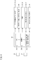
- the ice supply device C includes a controller 25 serving as a control unit. As illustrated in FIG.
- the controller 25 includes a CPU 25a, a memory 25b such as a RAM and a ROM, and a transmission and reception unit 25c that performs transmission to and reception from external devices, sensors, and the like.
- the controller 25 achieves various kinds of control concerning an operation of the ice making system S, including operation control of the ice supply device C, in such a manner that the CPU 25a executes a computer program stored in the memory 25b.
- the controller 25 controls driving of drive units or actuators such as electromagnetic valves 37, 73, and 91, a proportional control valve 83, and pumps 32 and 38, which will be described later.
- the controller 25 receives detection signals from temperature sensors 84 and 92 and a water level sensor 33 by the transmission and reception unit 25c.
- the controller 25 is communicably connected to a control unit 27 of the ice making device I, controls an operation of the ice making device I via the control unit 27, and receives a signal from a sensor or the like of the ice making device I via the control unit 27.
- a main control unit of the ice making system S can be attached to the ice making device I.
- the ice storage tank T is made of a metal material such as stainless steel or iron.
- the ice storage tank T has a rectangular cylindrical shape with a rectangular horizontal cross section.
- the ice storage tank T is a sealed container having a lid, but in FIG. 1 and FIG. 3 , the lid is not illustrated in order to facilitate understanding of a configuration of an upper part of an inside of the ice storage tank T.
- the pump 32 that transfers the seawater in the ice storage tank T into the inner pipe 11 of the ice making machine 1 by the seawater pipe 15 is disposed near a bottom of the inside of the ice storage tank T.
- the water level sensor 33 is provided in the ice storage tank T. On the basis of a detection signal from the water level sensor 33, the seawater is replenished and discharged as described later.
- the water level sensor 33 is detectable of a plurality of water levels in the ice storage tank T, and is disposed to be detectable of, for example, positions of 90%, 70%, 45%, 30%, and 25% of a height of the ice storage tank T from the bottom.
- a generally known sensor can be used as the water level sensor 33.
- a discharge path 90 that discharges the seawater in the ice storage tank T is connected to near the bottom of the ice storage tank T.
- the discharge path 90 includes an electromagnetic valve 91.
- the supply path 31 is a flow path or a passage for supplying sherbet ice produced by the ice making device I and stored in the ice storage tank T to the user.
- the supply path 31 has a supply port 39 that releases the sherbet ice taken out from the ice storage tank T at a downstream end.
- a pipe, a hose, or a combination thereof can be used as the supply path 31, a pipe, a hose, or a combination thereof can be used.
- the pump 38 is disposed in the supply path 31, and the sherbet ice in the ice storage tank T can be sucked and taken out to outside by driving the pump 38.
- a float 40 is a member that floats in the ice storage tank T apart from an inner wall 30 of the ice storage tank T.
- the float 40 in the present embodiment is a hollow body and can be made of a synthetic resin such as a vinyl chloride resin (PVC).
- PVC vinyl chloride resin
- the float 40 has a square shape in plan view and a substantially rhombic shape in side view. Specifically, an upper surface 40a of the float 40 has an upper inclined surface inclined from an outer edge toward a center of the float 40 so as to be away from a liquid level. Similarly, a bottom surface 40b of the float 40 has a lower inclined surface inclined from the outer edge toward the center of the float 40 so as to be away from the liquid level.
- a shape of the float 40 is not limited in the present disclosure, and a float having a circular shape in plan view, a float having a triangular shape, or a float having a polygonal shape having five or more sides can also be used.
- the upper surface and/or the bottom surface of the float 40 may be a flat surface instead of an inclined surface.
- a size of the float 40 is not limited in the present disclosure, but in a case where the float 40 having a square shape in plan view floats in the ice storage tank T having a rectangular inner wall in plan view, when a length (shorter length) of one side of the ice storage tank T is W, a length of one side of the float 40 having a square shape can be 0.3 W to 0.5 W, for example. In a case where the float 40 having a circular shape in a plan view floats in the ice storage tank T having a circular shape in a plan view, when D is an inner diameter of the ice storage tank T, an outer diameter of the float 40 having a circular shape can be set to 0.3 D to 0.5 D, for example.
- An opening 41 vertically penetrating is formed at the center (center in plan view) of the float 40.
- the opening 41 has a circular shape in plan view.
- a distal end 34a of a hose 34 constituting a part of the supply path 31 is inserted into the opening 41 and fixed to the float 40.
- the hose 34 has a bellows portion 34b at a base of the distal end 34a.
- the bellows portion 34b can expand and contract by a predetermined distance along a longitudinal direction or an axial direction of the hose 34.
- An end of the bellows portion 34b opposite to the distal end 34a is connected to an enlarged diameter portion 35a at an end of a pipe 35 constituting the supply path 31.
- a position of the pipe 35 is fixed by a fixing tool (not illustrated).
- One end of a chain 36 is fixed to each of four corners of the float 40 having a square shape.
- the other end of the chain 36 is locked to the inner wall 30 of the ice storage tank T.
- a length of each chain 36 is set to a length that allows vertical movement and horizontal movement within a certain range of the float 40.
- the float 40 can move up and down within a certain range by the presence of the bellows portion 34b. The presence of the chain 36 restricts horizontal movement of the float 40 beyond a certain range.
- the pipe 35, the hose 34, and the opening 41 constitute the supply path 31.
- the takeout port 42 is located on the bottom surface 40b of the float 40. In other words, the takeout port 42 is located below the liquid level of the sherbet ice stored in a tank body.
- a position of the takeout port 42 in a vertical direction is not limited in the present disclosure, but the size, shape, weight, and the like of the float 40 can be selected such that the takeout port 42 is positioned, for example, about 10 cm to 40 cm below a liquid level L of the sherbet ice.
- the sherbet ice near the liquid level in the ice storage tank T has an IPF higher than that of the sherbet ice near the bottom surface.
- the takeout port 42 at the distal end of the supply path 31 is disposed not at a lower part or the center but at the upper part of the ice storage tank T in the vertical direction, it is possible to supply sherbet ice having a high IPF to the user.
- the takeout port 42 at the distal end of the supply path 31 is disposed below the liquid level of the sherbet ice, it is possible to prevent air from being sucked from the takeout port 42 when the sherbet ice is sucked from the takeout port 42. Then, it is possible to prevent the pump 38 from being damaged by the sucked air.
- the bottom surface 40b of the float 40 has the lower inclined surface inclined from the outer edge of the float 40 toward the takeout port 42 so as to be away from the liquid level, the air in the liquid around the takeout port 42 can be released upward along the inclined surface. It is therefore possible to further prevent the air from being sucked from the takeout port 42 at the distal end of the supply path 31.
- the ice supply device C has a return flow path 50 that branches from the supply path 31 downstream of the pump 38 disposed in the supply path 31 and returns the sherbet ice to the ice storage tank T.
- the return flow path 50 is connected to the sherbet pipe 16 that returns seawater containing ice produced by the ice making machine 1 to the ice storage tank T.
- the return flow path 50 is provided with a safety valve 51. The safety valve 51 is opened when a pressure in the return flow path 50 is increased to exceed a predetermined pressure.
- the safety valve 51 also plays a role of opening and returning the sherbet ice into the ice storage tank T when the pressure in the return flow path 50 branched from the supply path 31 increases to exceed a predetermined pressure in a case where the pump 38 is driven even though the sherbet ice cannot be supplied from the supply port 39 due to a failure of the electromagnetic valve 37 provided in the supply path 31.
- the sherbet ice falls from a release port of a release pipe to be described later, which is disposed above the liquid level L of the sherbet ice stored in the ice storage tank T, and thus the sherbet ice near the liquid level can be disturbed. Further, it is possible to prevent the sherbet ice from being frozen.
- By opening the safety valve 51 to lower the pressure in the flow path of the sherbet ice it is possible to avoid failure of the pump 38 due to excessive pressure.
- an electromagnetic valve that is controllable to be opened and closed may be used.
- the electromagnetic valve is controlled by the CPU 25a of the controller 25 to be closed when the sherbet ice is being supplied to the user through the supply port 39 of the supply path 31, and is controlled to be open when the sherbet ice is not being supplied from the supply port 39 of the supply path 31.
- the sherbet ice can be returned into the ice storage tank T by operating the pump 38 and controlling the electromagnetic valve to be opened. This makes it possible to impart fluidity to the sherbet ice stored in the ice storage tank T and to prevent the sherbet ice from being frozen.
- the pump 38 disposed in the supply path 31 functions as a pump for supplying the sherbet ice in the ice storage tank T to the user from the supply port 39, and can function as a pump for returning the sherbet ice taken out from the ice storage tank T to the ice storage tank T via the return flow path 50 branching from the supply path 31.
- a supply pump and a return pump for the sherbet ice can be shared.
- the CPU 25a of the controller 25 By causing the CPU 25a of the controller 25 to interlock the operation of the pump 38 and opening and closing control of the electromagnetic valve that is controllable to be opened and closed, it is possible to prevent the sherbet ice from being frozen in the ice storage tank T.
- the pump 38 is driven constantly or periodically while the ice making device I is operating, and the sherbet ice in the ice storage tank T can flow and circulate through the return flow path constantly or periodically.
- the electromagnetic valve is controlled to be opened and closed by the CPU 25a of the controller 25 to be interlocked with the driving of the pump 38.
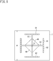
- a downstream end of the sherbet pipe 16 is branched into four branch pipes 60.
- a release pipe 61 is attached to a downstream end of each of the branch pipes 60.
- a plurality of (six in an example illustrated in FIG. 5 ) release ports 62 are formed on a lower surface of the release pipe 61.
- the branch pipes 60 and the release pipes 61 are disposed above the liquid level L of the sherbet ice stored in the ice storage tank T.
- a downstream end of the seawater supply pipe 70 that supplies seawater to the ice storage tank T is connected to the sherbet pipe 16.
- the seawater sucked from a seawater acquisition port by a pump (not illustrated) joins the sherbet pipe 16 via a sterilization and filtration device 72 and the electromagnetic valve 73, and is supplied from the release ports 62 of the release pipes 61 to the ice storage tank T.
- the sterilization and filtration device 72 is a device for removing foreign substances contained in the seawater and sterilizing bacteria contained in the seawater.
- the seawater can be supplied to the ice storage tank T using the seawater supply pipe 70 on the basis of the detection signal of the water level sensor 33 described above.
- the ice supply device C includes the water flow path 80 through which water flows and that joins the supply path 31 through which the sherbet ice is taken out of the ice storage tank T.
- the water flow path 80 joins the supply path 31 upstream of the pump 38 for sucking and taking out the sherbet ice from the ice storage tank T in a flow direction of the sherbet ice.
- the number of required pumps can be reduced to one from two.
- salt water containing salt in water can also be used.
- an input unit 26 (see FIG. 4 ) communicably connected to the controller 25 is provided.
- the user can take out a desired amount of sherbet ice having a desired salinity from the supply port 39 by inputting the salinity and the amount of sherbet ice to be taken out from the ice storage tank T.
- the water stored in the water tank 81 is sucked by the pump 38 and joins the supply path 31 via the proportional control valve 83 as a flow rate regulating valve.
- a temperature sensor 84 as a first temperature sensor is provided downstream of a junction of the water flow path 80 and the supply path 31 and downstream of the pump 38 to detect a temperature of the sherbet ice. Since there is a correlation between the salinity and the temperature of the sherbet ice, by detecting the temperature of the sherbet ice by the temperature sensor 84, the salinity can be calculated from the detected temperature. This calculation can be performed by the CPU 25a of the controller 25.
- an opening degree and/or an opening time of the proportional control valve 83 is adjusted by the CPU 25a of the controller 25 such that the calculated salinity becomes a target value on the basis of the calculated salinity, and thus the sherbet ice having a desired salinity can be obtained.
- a flow rate of the sherbet ice flowing through the supply path 31 and a flow rate of the water flowing through the water flow path 80 are configured to be substantially equal. This configuration can set a concentration of the sherbet ice taken out from the electromagnetic valve 37 to about a half of a concentration of the sherbet ice stored in the ice storage tank T.
- the opening degree of the proportional control valve 83 is 50%, a ratio of the flow rate of the sherbet ice flowing through the supply path 31 and the flow rate of the water flowing through the water flow path 80 are two to one. It is therefore possible to set the concentration of the sherbet ice stored taken out from the electromagnetic valve 37 to about two thirds of the concentration of the sherbet ice stored in the ice storage tank T.
- the concentration of the sherbet ice taken out from the electromagnetic valve 37 can be about two thirds of the concentration of the sherbet ice stored in the ice storage tank T.
- a concentration sensor 84 (first concentration sensor) that detects a salinity may be used.
- the opening degree and/or the opening time of the proportional control valve 83 can be adjusted by the controller 25 such that the salinity becomes a target value on the basis of the detected salinity.
- the temperature sensor 92 as a second temperature sensor that detects the temperature of the sherbet ice in the ice storage tank T is disposed in the ice storage tank T.
- the salinity of the sherbet ice can be obtained by the CPU 25a of the controller 25 on the basis of the temperature of the seawater before the operation and the temperature of the sherbet ice after a start of the operation that are detected by the temperature sensor 92.
- the CPU 25a of the controller 25 changes the opening degree and/or the opening time of the proportional control valve 83 on the basis of the salinity to adjust the flow rate of water to join from the water flow path 80 to the supply path 31. Accordingly, a salinity of the sherbet ice supplied to a user can be adjusted.
- concentration sensor 92 is also possible to use a concentration sensor 92 as a second concentration sensor instead of the temperature sensor 92 as the second temperature sensor.
- the CPU 25a of the controller 25 can obtain the concentration of the sherbet ice in the ice storage tank T by the concentration sensor 92.
- the salinity can be calculated from the detected temperature by the CPU 25a of the controller 25. Then, when the calculated salinity is not within a predetermined range, the CPU 25a of the controller 25 prohibits an operation of taking out the sherbet ice in the ice storage tank T.
- the IPF of the sherbet ice is also low, and the sherbet ice is not sufficiently used as sherbet ice.
- the sherbet ice in an insufficient state is prevented from being supplied to the user.
- the concentration sensor 92 as the second concentration sensor is used instead of the temperature sensor 92 as the second temperature sensor
- the CPU 25a of the controller 25 prohibits the operation of taking out the sherbet ice in the ice storage tank T when the salinity of the sherbet ice detected by the concentration sensor 92 is not within the predetermined range.
- the CPU 25a of the controller 25 controls the electromagnetic valve 91 and the electromagnetic valve 73 upon determination that the salinity calculated on the basis of the temperature detected by the temperature sensor 92 exceeds a predetermined value. Specifically, the CPU 25a of the controller 25 opens the electromagnetic valve 91 when the calculated salinity exceeds the predetermined value. As a result, the seawater in the ice storage tank T is discharged to outside via the discharge path 90. When a first predetermined condition is satisfied, the CPU 25a closes the electromagnetic valve 91 and then opens the electromagnetic valve 73 to supply the seawater to the ice storage tank T. When a second predetermined condition is satisfied, the CPU 25a closes the electromagnetic valve 73.
- the salinity of the seawater in the ice storage tank T can be reduced to less than a predetermined value, and as a result, the ice making device I can be continuously operated. Accordingly, ice making efficiency of the ice making system S can be improved.
- a salinity sensor can also be used as means for detecting the concentration of the seawater in the ice storage tank T.
- the "predetermined value” described above is not limited in the present disclosure, but can be, for example, 7%.
- the predetermined value can be appropriately set via an input unit (not illustrated) of the controller 25.
- the set predetermined value is stored in the memory 25b.
- the "first predetermined condition” and the “second predetermined condition” may be, for example, a decline in a water level as a division between water and ice to a certain position. Under the first predetermined condition, the CPU 25a of the controller 25 detects that the water level has declined to a first position by the water level sensor 33.
- the first position for example, a position of 45% of the height of the tank from the bottom can be selected from the plurality of water levels detected by the water level sensor 33. Since there is a possibility that the pump may be damaged if only ice is handled, when the water level declines to the first position, the water discharge is stopped and the water supply is started. Under the second predetermined condition, the CPU 25a of the controller 25 detects that the water level has risen to a second position by the water level sensor 33. As the second position, for example, a position of 90% of the height of the tank from the bottom can be selected from the plurality of water levels detected by the water level sensor 33. The first position and the second position can be appropriately set via an input unit (not illustrated) of the controller 25.
- the set first position and second position are stored in the memory 25b.
- the CPU 25a of the controller 25 detects the salinity of the sherbet ice in the ice storage tank T by the temperature sensor 92 disposed in the ice storage tank T (step S1).
- the CPU 25a of the controller 25 determines whether the salinity exceeds 7% (step S2), and advances the processing to step S3 upon determination that the salinity exceeds 7%.
- step S3 the CPU 25a transmits a command to stop the operation of the ice making device I to the control unit 27 of the ice making device I.
- the CPU 25a opens the electromagnetic valve 91 provided in the discharge path 90 connected to the ice storage tank T (step S4). As a result, the seawater near the bottom surface of the ice storage tank T is discharged.
- the discharged seawater may contain some sherbet ice.
- step S5 the CPU 25a determines whether the water level detected by the water level sensor 33 has declined to a water level lower than the first predetermined condition. Upon determination that the water level has declined to the water level lower than the first predetermined condition in step S5, the CPU 25a advances the processing to step S6 and closes the electromagnetic valve 91 in step S6. Next, the CPU 25a opens the electromagnetic valve 73 (step S7). As a result, the seawater (having a salinity of about 3.5%) is supplied into the ice storage tank T. Next, in step S8, the CPU 25a determines whether the water level detected by the water level sensor 33 has risen to a water level higher than the second predetermined condition.
- step S10 the CPU 25a transmits a command to start the operation of the ice making device I to the control unit of the ice making device I.
- the processing returns to step S1 after execution of step S10, and the CPU 25a of the controller 25 detects the salinity of the sherbet ice in the ice storage tank T by the temperature sensor 92 disposed in the ice storage tank T.
- a target salinity in the ice storage tank T can be set to, for example, 3.5% to 7%. By performing such control, the ice making device I can be continuously operated.
- the CPU 25a of the controller 25 may control the electromagnetic valve 91 of the discharge path 90 and the electromagnetic valve 73 of the seawater supply pipe 70 such that the salinity of the seawater in the ice storage tank T becomes the target salinity.
- the control in this case can be performed as follows.
- the CPU 25a of the controller 25 recognizes the salinity of seawater supplied from the seawater supply pipe 70.
- the CPU 25a of the controller 25 can control the electromagnetic valve 91 and the electromagnetic valve 73 such that the salinity when salt water having different concentrations is mixed in the ice storage tank T becomes the target salinity by calculating an amount of seawater discharged from the ice storage tank T and an amount of seawater supplied from the seawater supply pipe 70 when the salinity of the seawater in the ice storage tank T becomes a predetermined value.
- the first predetermined condition can be the amount of seawater discharged from the ice storage tank T
- the second predetermined condition can be the amount of seawater supplied from the seawater supply pipe 70.
- Water is supplied to the water tank 81 via a control valve 86.
- Afloat switch 87 is disposed in the water tank 81, and the control valve 86 is controlled to open and close on the basis of a detection signal from the float switch 87 to start and stop the supply of water to the water tank 81.
- Embodiment 1 the water flow path 80 through which water flows joins the supply path 31 through which the sherbet ice is taken out of the ice storage tank T.
- the salinity of the sherbet ice supplied to the user can be easily adjusted by adjusting the flow rate of water to join the supply path 31.
- the salinity of the sherbet ice can be adjusted only by adjusting the flow rate of water from the water flow path 80 to join to the supply path 31, which improves usability of the ice supply device C.
- the pump 38 is disposed downstream of the junction where the water flow path 80 joins the supply path 31 in the flow direction of the sherbet ice.
- the pump 38 By arranging the pump 38 downstream of the junction in the flow direction of the sherbet ice, one pump allows the sherbet ice and water to flow.
- the proportional control valve 83 is disposed in the water flow path 80, and the opening degree and/or the opening time of the proportional control valve 83 are controlled by the CPU 25a of the controller 25 such that the salinity of the sherbet ice after joining becomes a target value.
- the salinity of the sherbet ice after joining can be adjusted only by controlling the opening degree and/or the opening time of the proportional control valve 83 provided in the water flow path 80.
- the temperature sensor 84 that detects the temperature of the sherbet ice is provided downstream of the junction of the supply path 31 and the water flow path 80 in the flow direction of the sherbet ice, and the CPU 25a of the controller 25 controls the opening degree and/or the opening time of the proportional control valve 83 such that the detected temperature becomes a target value.
- the salinity of the sherbet ice after joining can be adjusted by controlling the proportional control valve 83 using the temperature by detected the temperature sensor 84. In this case, since there is a correlation between the salinity and the temperature of the sherbet ice, the salinity of the sherbet ice can be calculated from the temperature detected by the temperature sensor 84.
- the temperature sensor 92 is disposed in the ice storage tank T, and on the basis of the temperature of the seawater before the operation and the temperature of the sherbet ice after the start of the operation that are detected by the temperature sensor 92, the salinity of the sherbet ice is calculated by the CPU 25a of the controller 25. Then, on the basis of the calculated salinity, the salinity of the sherbet ice supplied to the user can be adjusted by adjusting the flow rate of water to join the supply path 31 from the water flow path 80.
- the temperature sensor 92 detects the temperature of the sherbet ice, and the CPU 25a of the controller 25 calculates the salinity from the detected temperature. Then, when the calculated salinity is not within a predetermined range, the CPU 25a of the controller 25 prohibits an operation of taking out the sherbet ice in the ice storage tank T.
- the salinity of the sherbet ice in the ice storage tank T is excessively low, the IPF of the sherbet ice is also low, and the sherbet ice is not sufficiently used as sherbet ice.
- the input unit 26 communicably connected to the controller 25 is provided, the user can take out a desired amount of sherbet ice having a desired salinity from the supply port 39 by inputting the salinity and the amount of sherbet ice to be taken out from the ice storage tank T.
- the supply path 31 includes the takeout port 42 for taking out the sherbet ice in the ice storage tank T, and the takeout port 42 is disposed below the liquid level L of the sherbet ice in the ice storage tank T by a predetermined distance. Since fine ice constituting the sherbet ice has a specific gravity smaller than that of seawater, the ice moves upward by buoyancy. Thus, the sherbet ice near the liquid level in the ice storage tank T has an IPF higher than that of the sherbet ice near the bottom surface.
- the sherbet ice having a high IPF can be supplied to the user.
- Embodiment 1 the water flow path 80 through which water flows joins the supply path 31 through which the sherbet ice is taken out of the ice storage tank T.
- the salinity of the sherbet ice supplied to the user can be easily adjusted by adjusting the flow rate of water to join the supply path 31.
- sherbet ice for refrigerating different types of saltwater fish is required after a predetermined amount of sherbet ice is supplied to the user
- the salinity of the sherbet ice can be easily adjusted only by adjusting the flow rate of water from the water flow path 80 to join to the supply path 31, which improves usability of the ice making system S.
- FIG. 7 is an explanatory diagram of an ice making system according to Embodiment 2 of the present disclosure.
- FIG. 8 is an explanatory diagram of a controller of the ice making system illustrated in FIG. 7 .
- the ice making system S according to the present embodiment includes the ice making device I and the ice supply device C as in Embodiment 1.
- the ice making system S according to the present embodiment further includes a cooling apparatus 100 and a temperature sensor (third temperature sensor) 103.
- the cooling apparatus 100 cools water flowing through the water flow path 80.
- the third temperature sensor 103 detects a temperature of the water cooled by the cooling apparatus 100.
- the cooling apparatus 100 and the third temperature sensor 103 according to the present embodiment are disposed in the water tank 81 that is a component of the ice supply device C.
- the cooling apparatus 100 includes a heat exchanger (third heat exchanger).
- the heat exchanger constituting the cooling apparatus 100 is also referred to as a cooling heat exchanger 100.
- the cooling heat exchanger 100 is inserted into the water tank 81 to exchange heat with water in the water tank 81.
- the cooling heat exchanger 100 can adopt, for example, a configuration in which a heat transfer tube through which a refrigerant flows is wound in a coil shape.
- the cooling heat exchanger 100 is supplied with the refrigerant used in the ice making device I.
- the ice making device I includes the ice making machine 1 constituting the use-side heat exchanger (second heat exchanger), the compressor 2, the heat source-side heat exchanger 3 (first heat exchanger), the four-way switching valve 4, the use-side expansion valve 5, the heat source-side expansion valve 6, the internal heat exchanger 7, and the receiver 8. These devices are connected by a refrigerant pipe 96 to constitute a refrigerant circuit 95.
- a first branch pipe 97 branches from a refrigerant pipe 96a between an outflow portion 3a of the liquid refrigerant in the heat source-side heat exchanger 3 and the use-side expansion valve 5, specifically, from the refrigerant pipe 96a between the receiver 8 and the internal heat exchanger 7.
- a second branch pipe 98 branches from a refrigerant pipe 96b between an outflow portion 1a of a gas refrigerant in the ice making machine 1 and a suction portion 2a of a gas refrigerant of the compressor 2, specifically, from the refrigerant pipe 96b between the internal heat exchanger 7 and the four-way switching valve 4.
- the first branch pipe 97 is connected to a refrigerant inlet 100a of the cooling heat exchanger 100.
- the second branch pipe 98 is connected to a refrigerant outlet 100b of the cooling heat exchanger 100.
- the refrigerant having dissipated heat in the heat source-side heat exchanger 3 passes through the heat source-side expansion valve 6 and the receiver 8, branches from the refrigerant pipe 96a to the first branch pipe 97, and flows into the cooling heat exchanger 100.
- the refrigerant having passed through the cooling heat exchanger 100 passes through the second branch pipe 98, joins the refrigerant pipe 96b, passes through the four-way switching valve 4, and is sucked into the compressor 2.
- the cooling heat exchanger 100 is provided in the refrigerant circuit 95 in parallel with the ice making machine 1.
- the first branch pipe 97 is provided with a cooling expansion valve 101 that decompresses the refrigerant.
- the liquid refrigerant flowing through the first branch pipe 97 is decompressed by the cooling expansion valve 101 to become a low-temperature low-pressure gas-liquid two-phase refrigerant, and is supplied to the cooling heat exchanger 100.
- the cooling heat exchanger 100 causes heat exchange between the water in the water tank 81 and the refrigerant. By this heat exchange, the refrigerant absorbs heat from the water in the water tank 81 and evaporates, and the water in the water tank 81 is cooled.
- the cooling expansion valve 101 is opened to supply the refrigerant to the cooling heat exchanger 100, and is closed to stop supplying the refrigerant to the cooling heat exchanger 100.
- the cooling expansion valve 101 functions as a control valve that controls the flow of the refrigerant to the cooling heat exchanger 100.
- the cooling expansion valve 101 opens and closes on the basis of the temperature detected by the third temperature sensor 103. Specifically, when the temperature detected by the third temperature sensor 103 exceeds a predetermined upper limit temperature T th1 , the cooling expansion valve 101 is opened to cool the water in the water tank 81. Specifically, when the temperature detected by the third temperature sensor 103 exceeds a predetermined lower limit temperature T th2 , the cooling expansion valve 101 is closed to stop cooling the water in the water tank 81.
- the upper limit temperature T th1 can be set to a temperature at which the sherbet ice having joined the water in the supply path 31 does not excessively melt.
- the upper limit temperature T th1 can be set to 5°C.
- the lower limit temperature T th2 can be set to a temperature at which the water in the water tank 81 does not freeze.
- the lower limit temperature T th2 can be set to 2°C.
- the third temperature sensor 103 is disposed in a lower part of the water tank 81 (below a center of the water tank 81 in the vertical direction). Thus, a lower temperature of the water in the water tank 81 can be detected.
- the third temperature sensor 103 is preferably disposed below the cooling heat exchanger 100.
- the third temperature sensor 103 is more preferably disposed near a bottom surface of the water tank 81.
- the second branch pipe 98 is provided with a fifth temperature sensor 105.
- the fifth temperature sensor 105 detects a temperature of the refrigerant having passed through the cooling heat exchanger 100. When the cooling expansion valve 101 is open, an opening degree of the cooling expansion valve 101 is adjusted such that a degree of superheating of the refrigerant obtained using a detection result of the fifth temperature sensor 105 becomes a predetermined set value.
- the control unit 27 includes a CPU 27a, a memory 27b such as a RAM and a ROM, and a transmission and reception unit 27c that performs transmission to and reception from external devices, sensors, and the like.
- the control unit 27 achieves various kinds of control concerning the operation of the ice making system S, including the operation control of the ice making device I, in such a manner that the CPU 27a executes a computer program stored in the memory 27b.
- the control unit 27 controls driving of the compressor 2, the four-way switching valve 4, the expansion valves 5, 6, and 101, and the like.
- the control unit 27 receives a detection signal from the fifth temperature sensor 105 or the like through the transmission and reception unit 27c.
- the control unit 27 is communicably connected to the controller 25 of the ice supply device C, and acquires detection results of the temperature sensors 103 and 104 and the like received by the controller 25.
- the water flow path 80 is provided with a fourth temperature sensor 104.
- the fourth temperature sensor 104 detects the temperature of water immediately before joining the supply path 31.
- the temperature of the water joining the supply path 31 is high, the sherbet ice after joining is easily melted, and there is a possibility that the salinity of the sherbet ice decreases and the temperature rapidly increases. Therefore, the temperature of the water before joining is detected by the fourth temperature sensor 104, and the opening degree of the proportional control valve 83 is adjusted on the basis of the detection result.
- the opening degree of the proportional control valve 83 is adjusted by the controller 25 as in Embodiment 1.
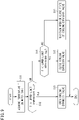
- FIG. 9 is a flowchart illustrating an example of water temperature control in the water tank.
- the control unit 27 cools the water in the water tank 81 in accordance with a procedure illustrated in FIG. 9 and maintains a water temperature within a predetermined range.
- the control unit 27 first acquires a water temperature T by receiving a detection signal from the third temperature sensor 103 in the water tank 81 (step S11).
- control unit 27 determines whether the water temperature T exceeds the predetermined upper limit temperature T th1 (step S12).
- the upper limit temperature T th1 can be set to 5°C as described above.
- the control unit 27 performs control to open the cooling expansion valve 101 in order to cool the water in the water tank 81 (step S13).
- step S12 determines whether the water temperature T is lower than the predetermined lower limit temperature T th2 (step S14).
- the lower limit temperature T th2 can be set to 2°C as described above.
- step S15 the control unit 27 performs control to close the cooling expansion valve 101 (step S15). Specifically, the control unit 27 closes the cooling expansion valve 101 when the cooling expansion valve 101 is open, and maintains a closed state when the cooling expansion valve 101 is closed. As a result, cooling of the water in the water tank 81 is stopped.
- step S16 When the determination in step S14 is negative (NO), the control unit 27 maintains an open or close state of the cooling expansion valve 101 (step S16). Specifically, the control unit 27 maintains an open state when the cooling expansion valve 101 is open, and maintains a closed state when the cooling expansion valve 101 is closed.
- the control unit 27 can maintain the temperature of the water in the water tank 81 within a predetermined range from T th1 to T th2 by repeating the above procedure.
- the controller 25 adjusts the opening degree of the proportional control valve 83 in accordance with the temperature of the water flowing through the water flow path 80. Specifically, the controller 25 obtains an amount of water to join the sherbet ice in the ice storage tank T from the temperature (salinity) of the sherbet ice in the ice storage tank T, the temperature (salinity) of the sherbet ice that the user wants to take out, and the temperature of the water to join the sherbet ice, and adjusts the opening degree of the proportional control valve 83.
- the controller 25 makes the opening degree of the proportional control valve 83 different between when the temperature of the water flowing through the water flow path 80 is 2°C and when the temperature is 5°C. Specifically, the controller 25 makes the opening degree of the proportional control valve 83 smaller when the water temperature is 5°C than when the water temperature is 2°C.
- the opening degree of the proportional control valve 83 is the same between when the temperature of the water is 2°C and when the temperature of the water is 5°C, the IPF of the sherbet ice changes more greatly and the temperature of the sherbet ice reaches the set temperature more quickly when the water at 5°C joins than when the water at 2°C joins. Therefore, there is a high possibility that the temperature of the sherbet ice exceeds the set temperature.
- the controller 25 When the water temperature is 5°C, the controller 25 according to the present embodiment makes the opening degree of the proportional control valve 83 smaller than the opening degree when the water temperature is 2°C to decrease the change in the IPF and increase the time to reach the set temperature. It is therefore possible to prevent the temperature of the sherbet ice from exceeding the set temperature.
- the controller 25 since the water temperature in the water tank 81 is controlled to 2°C to 5°C, the controller 25 sets the lowest 2°C as a "reference temperature” and sets the opening degree of the proportional control valve 83 at this time as a "reference opening degree". When the water temperature exceeds the reference temperature, the controller 25 operates the opening degree of the proportional control valve 83 from the reference opening degree in a closing direction. The controller 25 is configured to operate the opening degree of the proportional control valve 93 to be larger in the closing direction as the temperature of water in excess of the reference temperature increases.
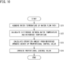
- FIG. 10 is a flowchart illustrating an example of the control of the proportional control valve.
- the controller 25 controls the opening degree of the proportional control valve by a procedure illustrated in FIG. 10 to adjust the temperature of the sherbet ice to the set temperature.
- the controller 25 first acquires the water temperature by receiving a detection signal from the fourth temperature sensor 104 in the water flow path 80 (step S21).
- the controller 25 calculates a difference between the water temperature and a reference temperature (for example, 2°C) (step S22). Then, the controller 25 calculates an operation amount (closing amount) of the proportional control valve 83 from the reference opening degree using the difference (step S23).
- a reference temperature for example, 2°C
- controller 25 operates the proportional control valve 83 in accordance with the calculated operation amount to join the water from the water flow path 80 to the supply path 31 (step S24).
- the ice supply device C and the ice making system S according to Embodiment 2 have the following action and effects in addition to the action and effects in Embodiment 1.
- the cooled water flows in the water flow path 80. It is therefore possible to prevent the sherbet ice from being melted by the joined water and to supply the sherbet ice having a high IPF to the user.
- the ice supply device C includes the cooling apparatus 100 that cools the water flowing through the water flow path 80. It is therefore possible to prevent the sherbet ice from being melted by the joined water and to supply the sherbet ice having a high IPF to the user.
- the ice making system S according to Embodiment 2 includes the refrigerant circuit 95 that produces sherbet ice and the ice supply device C.
- the sherbet ice produced by the refrigerant circuit 95 can be stored in the ice storage tank T, and water can join to the supply path 31 through which the sherbet ice is taken out of the ice storage tank T. Accordingly, a salinity of the sherbet ice supplied to a user can be adjusted.
- the refrigerant circuit 95 includes the compressor 2, the heat source-side heat exchanger (first heat exchanger) 3 that dissipates heat from the refrigerant compressed by the compressor 2, and the ice making machine 1 which is the use-side heat exchanger (second heat exchanger) that exchanges heat between the refrigerant having dissipated heat in the heat source-side heat exchanger 3 and a medium to be cooled serving as a raw material of sherbet ice to cool the medium to be cooled. Therefore, the medium to be cooled can be cooled by the refrigerant flowing through the refrigerant circuit 95 to produce sherbet ice.
- the refrigerant circuit 95 further includes the cooling heat exchanger (third heat exchanger) 100 that exchanges heat between the refrigerant having dissipated heat in the heat source-side heat exchanger 3 and water to be flowed through the water flow path 80 to cool the water. Therefore, the water flowing through the water flow path 80 can be cooled using the refrigerant of the refrigerant circuit 95 that produces the sherbet ice.
- the water tank 81 that stores water cooled by the cooling heat exchanger 100 is further provided. Therefore, the cooled water can be stably supplied to the supply path 31.
- Embodiment 2 provided are the third temperature sensor 103 that detects the temperature of the water in the water tank 81, the cooling expansion valve (control valve) 101 that controls the flow of the refrigerant in the cooling heat exchanger 100, and the control unit (second control unit) 27 that controls the operation of the cooling expansion valve 101 on the basis of the temperature detected by the third temperature sensor 103.
- the temperature of the water in the water tank 81 can be controlled appropriately.
- the third temperature sensor 103 is disposed in a lower part of the inside of the water tank 81. Therefore, a temperature as low as possible of the water stored in the water tank 81 can be detected, and by controlling the operation of the cooling expansion valve 101 on the basis of this temperature, it is possible to prevent the water in the water tank 81 from being cooled more than necessary (frozen).
- the ice storage tank has a rectangular cylindrical shape having a rectangular horizontal cross section, but the present disclosure is not limited thereto.
- the ice storage tank may be a tank having a cylindrical shape with a circular horizontal cross section, or a tank having a polygonal horizontal cross section.
- an evaporator in which a refrigerant is ejected by a nozzle into the annular space between the inner pipe and the outer pipe can be used.
- the horizontal double pipe ice making machine in which the axes of the inner pipe and the outer pipe are disposed horizontally is exemplified as the ice making machine.
- the configuration of the ice making machine is not limited in the present disclosure, and ice making machines having various shapes and structures, such as a vertical double pipe ice making machine in which the axes of the inner pipe and the outer pipe are disposed vertically can be adopted.
- the adjustment of the salinity and the amount of the sherbet ice supplied to the user, which are input to the input unit 26, is not illustrated.
- the salinity of the sherbet ice can be adjusted by controlling the opening degree of the proportional control valve 83 to set a value detected by the first temperature sensor 84 to a temperature corresponding to the target salinity.
- the supply amount of sherbet ice can be adjusted by providing a sensor (not illustrated) capable of measuring a flow rate near the electromagnetic valve 37 and by opening the electromagnetic valve 37 for a time until a target amount of sherbet ice is supplied.
- the cooling heat exchanger as the cooling apparatus may be disposed outside the water tank.
- a water circuit that draws water from the water tank by a pump to circulate can be provided, and the cooling heat exchanger can be provided in the water circuit.
- the cooling heat exchanger as the cooling apparatus may be provided in a refrigerant circuit other than the refrigerant circuit in the ice making device.
- the cooling apparatus need not use a refrigerant.
- the water temperature is detected by the temperature sensor provided in the water flow path for the control of the proportional control valve, but the water temperature may be detected by the temperature sensor in the water tank.
- the proportional control valve can be controlled more accurately by detecting the water temperature immediately before joining the supply path by the temperature sensor provided in the water flow path.
- control of the proportional control valve may be feedback control based on the temperature or salinity of the sherbet ice after joining to the water.
- a temperature sensor may be provided not only in the lower part but also in the upper part of the water tank.
- the temperature range of the water in the water tank is exemplified as 2°C to 5°C, but may be a temperature range different from this temperature range.
Landscapes
- Engineering & Computer Science (AREA)
- Physics & Mathematics (AREA)
- Mechanical Engineering (AREA)
- Thermal Sciences (AREA)
- General Engineering & Computer Science (AREA)
- Production, Working, Storing, Or Distribution Of Ice (AREA)
Abstract
Description
- The present disclosure relates to an ice supply device and an ice making system.
- In order to refrigerate saltwater fish or the like, sherbet ice produced from salt water such as seawater may be used. The sherbet ice generated by an ice making device is stored in an ice storage tank and supplied to a user by a pump as needed.
- When saltwater fish is refrigerated using sherbet ice, it is known that a temperature suitable for cold storage varies depending on a type and size of the fish. When the saltwater fish is refrigerated at a low temperature less than a temperature suitable for the saltwater fish to be refrigerated, the body of the saltwater fish may be frozen, and a commercial value of the fish may be greatly impaired.
- Therefore, it has been proposed that a salinity of the sherbet ice is adjusted when the sherbet ice produced by the ice making device is supplied to a location of use (see, for example, Patent Literature 1). Note that there is a correlation between the temperature and the salinity of the sherbet ice, and the temperature can be indirectly adjusted by adjusting the salinity.
- In a production apparatus for sherbet ice mixed with salt water disclosed in
Patent Literature 1, fresh water is poured into an ice storage tank to adjust the salinity of the sherbet ice mixed with salt water in the ice storage tank, and the sherbet ice after the adjustment is taken out from the ice storage tank. - PATENT LITERATURE 1:
Japanese Laid-Open Patent Publication No. 2008-281293 - However, in the production apparatus disclosed in
PATENT LITERATURE 1, the fresh water is poured into the ice storage tank storing the produced sherbet ice to adjust the salinity of the sherbet ice, and thus only sherbet ice having a certain specific salinity can be obtained. When it is desired to refrigerate different types of saltwater fish, it is therefore difficult to adjust the salinity of the sherbet ice to a salinity suitable for the saltwater fish. - An object of the present disclosure is to provide an ice supply device and an ice making system capable of adjusting a salinity of sherbet ice supplied to a user.
-
- (1) An ice supply device of the present disclosure includes an ice storage tank that stores sherbet ice, a supply path through which the sherbet ice is taken out of the ice storage tank, and a water flow path that joins the supply path and through which water flows.
- In the ice supply device of the present disclosure, the water flow path through which water flows joins the supply path through which the sherbet ice is taken out of the ice storage tank. Accordingly, a salinity of the sherbet ice supplied to a user can be adjusted.
- (2) The ice supply device according to (1) desirably further includes a pump disposed downstream of a junction at which the water flow path joins the supply path in a flow direction of the sherbet ice. By arranging the pump downstream of the junction in the flow direction of the sherbet ice, one pump allows the sherbet ice and water to flow.
- (3) The ice supply device according to (1) or (2), desirably further includes a flow rate regulating valve provided in the water flow path, and a control unit that controls the flow rate regulating valve for a salinity of the sherbet ice after joining to become a target value. The salinity of the sherbet ice after joining can be adjusted by controlling the flow rate regulating valve provided in the water flow path by the control unit.
- (4) The ice supply device according to (3) desirably further includes a first temperature sensor that detects a temperature of the sherbet ice or a first concentration sensor that detects a salinity of the sherbet ice downstream of the junction in the flow direction of the sherbet ice, in which the control unit controls the flow rate regulating valve for the temperature detected by the first temperature sensor or the salinity detected by the first concentration sensor to become a target value. The salinity of the sherbet ice after joining can be adjusted by controlling the flow rate regulating valve using the temperature or the concentration detected by the first temperature sensor or the first concentration sensor.
- (5) The ice supply device according to (3) desirably further includes a first temperature sensor that detects a temperature of the sherbet ice downstream of the junction in the flow direction of the sherbet ice, in which the control unit calculates a salinity from the temperature detected by the first temperature sensor and controls the flow rate regulating valve for the salinity having been calculated to become a target value. Since there is a correlation between the salinity and the temperature of the sherbet ice, by detecting the temperature of the sherbet ice by the first temperature sensor, the salinity can be calculated from the detected temperature. Then, the control unit adjusts the flow rate of water to join the supply path by controlling the flow rate regulating valve such that the calculated salinity becomes the target value, and thus the salinity of the sherbet ice after joining can be adjusted.
- (6) In the ice supply device according to (3) to (5), the control unit desirably controls an opening degree and/or an opening time of the flow rate regulating valve. The control unit can adjust the flow rate of the water to join the supply path by controlling the opening degree and/or the opening time of the flow rate regulating valve.
- (7) The ice supply device according to (3) to (6) desirably further includes a second concentration sensor that detects a salinity of the sherbet ice in the ice storage tank, in which the control unit prohibits an operation of taking out the sherbet ice in the ice storage tank when the salinity detected by the second concentration sensor is not within a predetermined range. By prohibiting the operation of taking out the sherbet ice in the ice storage tank when the detected salinity is not within the predetermined range, the sherbet ice in an insufficient state is prevented from being supplied to the user.
- (8) The ice supply device according to (1) to (7) desirably further includes a second temperature sensor that detects a temperature of the sherbet ice in the ice storage tank, and a salinity calculation unit that calculates a salinity of the sherbet ice based on a temperature of a medium to be cooled supplied to the ice storage tank, the temperature of the medium to be cooled being detected by the second temperature sensor before an operation of the ice making device, and a temperature of the sherbet ice stored in the ice storage tank, the temperature of the sherbet ice being detected by the second temperature sensor after a start of the operation of the ice making device. The salinity of the sherbet ice can be calculated by the salinity calculation unit on the basis of the temperature of the medium to be cooled before the operation and the temperature of the sherbet ice after the start of the operation that are detected by the second sensor.
- (9) The ice supply device according to (1) to (8) desirably further includes an input unit that receives a salinity and an amount of the sherbet ice taken out from the ice storage tank. The user can take out a desired amount of sherbet ice having a desired salinity by inputting the salinity and the amount of sherbet ice in the input unit.
- (10) In the ice supply device according to (1) to (9), the supply path desirably includes a takeout port through which the sherbet ice in the ice storage tank is taken out, the takeout port being disposed in the ice storage tank, and the takeout port is desirably disposed below a liquid level of the sherbet ice in the ice storage tank by a predetermined distance. By taking out the sherbet ice near the liquid level from the takeout port disposed below the liquid level of the sherbet ice in the ice storage tank T by a predetermined distance, sherbet ice having a high ice packing factor (IPF: a ratio of a weight of ice to a total weight (weight of ice/(weight of ice + weight of water))) can be supplied to the user.
- (11) In the ice supply device according to (1) to (10), cooled water desirably flows through the water flow path. By joining the cooled water to the supply path, the sherbet ice can be prevented from being melted, and the sherbet ice having a high IPF can be supplied to the user.
- (12) The ice supply device according to (11) desirably includes a cooling apparatus that cools the water to be flowed through the water flow path.
- (13) An ice making system of the present disclosure includes a refrigerant circuit that produces the sherbet ice and the ice supply device according to (1) to (12).
- In the ice making system of the present disclosure, the sherbet ice produced by the refrigerant circuit can be stored in the ice storage tank, and the water flow path through which water flows joins to the supply path through which the sherbet ice is taken out of the ice storage tank. Accordingly, a salinity of the sherbet ice supplied to a user can be adjusted.
- (14) In the ice making system according to (13), the refrigerant circuit desirably includes a compressor, a first heat exchanger that dissipates heat from a refrigerant compressed by the compressor, and a second heat exchanger that exchanges heat between the refrigerant having dissipated heat in the first heat exchanger and a medium to be cooled serving as a raw material of the sherbet ice and cools the medium to be cooled.
- In this configuration, the medium to be cooled can be cooled by the refrigerant flowing through the refrigerant circuit to produce sherbet ice.
- (15) The ice making system according to (14), the refrigerant circuit desirably further includes a third heat exchanger that exchanges heat between the refrigerant having radiated heat in the first heat exchanger and the water to be flowed through the water flow path and cools the water.
- In this configuration, the water to be flowed through the water flow path can be cooled using the refrigerant of the refrigerant circuit that produces the sherbet ice.
- (16) The ice making system according to (15) desirably further includes a water tank that stores the water cooled by the third heat exchanger.
- In this configuration, the cooled water can be stably supplied to the supply path.
- (17) The ice making system according to (16) desirably further includes a third temperature sensor that detects a temperature of the water in the water tank, a control valve that controls a flow of the refrigerant in the third heat exchanger, and a second control unit that controls an operation of the control valve based on the temperature detected by the third temperature sensor.
- In this configuration, the temperature of the water in the water tank can be detected appropriately.
- (18) In the ice making system according to (17), the third temperature sensor is desirably disposed in a lower part of an inside of the water tank.
- In this configuration, a lower temperature of the water stored in the water tank can be detected by the third temperature sensor, and by controlling the operation of the control valve on the basis of this temperature, it is possible to prevent the water in the water tank from being cooled more than necessary (frozen).
- (19) An ice making system of the present disclosure includes an ice making device and the ice supply device according to any of (1) to (12).
- In the ice making system of the present disclosure, the water flow path through which water flows joins the supply path through which the sherbet ice is taken out of the ice storage tank. Accordingly, a salinity of the sherbet ice supplied to a user can be adjusted.
-
-
FIG. 1 is an explanatory diagram of an ice making system according toEmbodiment 1 of the present disclosure. -
FIG. 2 is an explanatory diagram of an ice making machine in the ice making system illustrated inFIG. 1 . -
FIG. 3 is an explanatory diagram of an ice supply device including an ice storage tank in the ice making system illustrated inFIG. 1 . -
FIG. 4 is an explanatory diagram of a controller of the ice supply device illustrated inFIG. 3 . -
FIG. 5 is an explanatory plan view of an inside of the ice storage tank. -
FIG. 6 is a flowchart of an example of control for adjusting a salinity of seawater in the ice storage tank. -
FIG. 7 is an explanatory diagram of an ice making system according toEmbodiment 2 of the present disclosure. -
FIG. 8 is an explanatory diagram of a controller of the ice making system illustrated inFIG. 7 . -
FIG. 9 is a flowchart illustrating an example of water temperature control in a water tank. -
FIG. 10 is a flowchart illustrating an example of control of a proportional control valve. - An ice supply device and an ice making system of the present disclosure will be described in detail below with reference to the accompanying drawings. The present disclosure should not be limited to the following exemplification, but is intended to include any modification recited in the claims within meanings and a scope equivalent to the scope of the claims.
-
FIG. 1 is an explanatory diagram of an ice making system S according toEmbodiment 1 of the present disclosure,FIG. 2 is an explanatory diagram of anice making machine 1 in the ice making system S illustrated inFIG. 1 , andFIG. 3 is an explanatory diagram of an ice supply device C including an ice storage tank T in the ice making system S illustrated inFIG. 1 . - The ice making system S includes an ice making device I and the ice supply device C. The ice making device I and the ice storage tank T which is a component of the ice supply device C are connected to each other by a pipe.
- The ice making device I produces sherbet ice from a medium to be cooled by exchanging heat with a refrigerant. In the present embodiment, seawater is used as the medium to be cooled, and the ice making device I produces fine ice using the seawater as a raw material, and returns sherbet ice mixed with seawater, in which the produced fine ice and the seawater are mixed, to the ice storage tank T. The sherbet ice is also referred to as slurry ice, ice slurry, slough ice, or liquid ice. As the medium to be cooled, for example, salt water containing salt in water can be used instead of seawater. The "water referred herein includes industrial water, tap water, and fresh water that are substantially free of salt.
- The ice making device I includes a
compressor 2, a heat source-side heat exchanger 3 (first heat exchanger), a four-way switching valve 4, a use-side expansion valve 5, a heat source-side expansion valve 6, aninternal heat exchanger 7, and areceiver 8, in addition to theice making machine 1 constituting a use-side heat exchanger (second heat exchanger). These devices are connected by arefrigerant pipe 96 to constitute arefrigerant circuit 95. - As illustrated in
FIG. 1 andFIG. 2 , theice making machine 1 includes an evaporator 13 (second heat exchanger) including aninner pipe 11 and anouter pipe 12, and anice scraper 14. Theice making machine 1 is a horizontal double pipe ice making machine in which axes of theinner pipe 11 and theouter pipe 12 are disposed horizontally. In theevaporator 13, liquid refrigerant passes through most of anannular space 24 between theinner pipe 11 and theouter pipe 12. - The
inner pipe 11 is an element through which the seawater serving as the medium to be cooled passes. Theinner pipe 11 is made of a metal material such as stainless steel or iron. Theinner pipe 11 has a cylindrical shape, and is disposed in theouter pipe 12. Both ends of theinner pipe 11 are closed. In theinner pipe 11, theice scraper 14 is disposed to scrape off ice produced on an inner peripheral surface of theinner pipe 11 and to disperse the ice into the seawater in theinner pipe 11. Aseawater pipe 15 that supplies the seawater in the ice storage tank T into theinner pipe 11 is connected to one axial end of theinner pipe 11. Asherbet pipe 16 that returns the seawater from theinner pipe 11 to the ice storage tank T is connected to the other axial end of theinner pipe 11. - The
outer pipe 12 has a cylindrical shape, and is made of a metal material such as stainless steel or iron as in theinner pipe 11. A plurality of (three in an illustrated example)refrigerant inlet pipes 17 branched downstream of the use-side expansion valve 5 are connected to a lower part of theouter pipe 12. Arefrigerant outlet pipe 18 leading to theinternal heat exchanger 7 is connected to an upper part of theouter pipe 12. In the present embodiment, threerefrigerant inlet pipes 17 are provided, but the number ofrefrigerant inlet pipes 17 may be two or less or four or more. The number ofrefrigerant outlet pipes 18 is one, but may be two or more. - The
ice scraper 14 includes ashaft 19, support bars 20,blades 21, and amotor 22. Theshaft 19 has the other axial end that extends outward from aflange 23 provided at the other axial end of theinner pipe 11. The other axial end of theshaft 19 is connected to themotor 22 that drives theshaft 19. The support bars 20 are disposed upright on a peripheral surface of theshaft 19 at predetermined intervals, and theblades 21 are attached to distal ends of the support bars 20. Each of theblades 21 is, for example, a band plate-shaped member made of a synthetic resin. Each of theblades 21 has a tapered shape directed forward in a rotational direction. - In a normal ice making operation, the four-
way switching valve 4 is maintained at a state indicated by a solid line inFIG. 1 . High-temperature high-pressure gas refrigerant discharged from thecompressor 2 flows through the four-way switching valve 4 into the heat source-side heat exchanger 3 functioning as a condenser, exchanges heat with air provided by the operation of thefan 10, and is condensed and liquefied. The liquefied refrigerant then flows into the use-side expansion valve 5 via the heat source-side expansion valve 6 in a fully open state, thereceiver 8, and theinternal heat exchanger 7. The refrigerant is decompressed to have a predetermined low pressure by the use-side expansion valve 5, and supplied through therefrigerant inlet pipe 17 into theannular space 24 between theinner pipe 11 and theouter pipe 12 that constitute theevaporator 13. - The refrigerant ejected into the
annular space 24 exchanges heat with the seawater supplied into theinner pipe 11 to evaporate. The seawater containing fine ice produced by cooling by evaporation of the refrigerant flows out of thesherbet pipe 16 and returns to the ice storage tank T. The refrigerant gasifies by the evaporation in theice making machine 1. Thereafter, the refrigerant is sucked into thecompressor 2. At that time, if the refrigerant containing liquid enters thecompressor 2 without being completely evaporated in theice making machine 1, thecompressor 2 may malfunction due to a sudden increase in pressure inside a compressor cylinder (liquid compression) and a decrease in viscosity of a refrigeration oil. Therefore, the low-pressure refrigerant that has left theice making machine 1 to protect thecompressor 2 exchanges heat with the high-pressure refrigerant that has passed through thereceiver 8 in theinternal heat exchanger 7, is heated, and returns to thecompressor 2. Theinternal heat exchanger 7 is of a double pipe type. The low-pressure refrigerant from theice making machine 1 exchanges heat with the high-pressure refrigerant when passing through the space between the inner pipe and the outer pipe of theinternal heat exchanger 7. The refrigerant is thus heated and then returns to thecompressor 2. - If the flow of the seawater is stagnated in the
inner pipe 11 of theice making machine 1, the ice is accumulated in the inner pipe 11 (ice accumulation) to hinder the operation of theice making machine 1. In this case, a defrosting operation (a heating operation) is performed for melting the ice in theinner pipe 11. At this time, the four-way switching valve 4 is maintained at a state indicated by a broken line inFIG. 1 . Thecompressor 2 discharges the high-temperature high-pressure gas refrigerant. The gas refrigerant flows into the annular space between theinner pipe 11 and theouter pipe 12 of theice making machine 1 via the four-way switching valve 4 and theinternal heat exchanger 7. The gas refrigerant exchanges heat with the ice-containing seawater in theinner pipe 11 to be condensed and liquefied. The liquefied refrigerant then flows into the heat source-side expansion valve 6 via the use-side expansion valve 5 in a fully open state, theinternal heat exchanger 7, and thereceiver 8. The heat source-side expansion valve 6 decompresses the liquefied refrigerant to a predetermined low pressure. Thereafter, the refrigerant flows into the heat source-side heat exchanger 3 functioning as an evaporator. During the defrosting operation, in the heat source-side heat exchanger 3 functioning as an evaporator, the refrigerant gasifies by exchanging heat with air provided by the operation of thefan 10. Thereafter, the refrigerant is sucked into thecompressor 2. - As illustrated in
FIG. 3 , the ice supply device C is a device that supplies sherbet ice produced by the ice making device I to a user. The ice supply device C includes the ice storage tank T that stores sherbet ice, asupply path 31, and awater flow path 80 that joins thesupply path 31 and through which water flows. Thesupply path 31 includes an on-off valve. By opening the on-off valve, sherbet ice is supplied to the user. In the present embodiment, the on-off valve is anelectromagnetic valve 37, but may be a valve or the like manually opened by the user. The ice supply device C includes acontroller 25 serving as a control unit. As illustrated inFIG. 4 , thecontroller 25 includes aCPU 25a, amemory 25b such as a RAM and a ROM, and a transmission andreception unit 25c that performs transmission to and reception from external devices, sensors, and the like. Thecontroller 25 achieves various kinds of control concerning an operation of the ice making system S, including operation control of the ice supply device C, in such a manner that theCPU 25a executes a computer program stored in thememory 25b. Thecontroller 25 controls driving of drive units or actuators such aselectromagnetic valves proportional control valve 83, and pumps 32 and 38, which will be described later. In addition, thecontroller 25 receives detection signals fromtemperature sensors water level sensor 33 by the transmission andreception unit 25c. Thecontroller 25 is communicably connected to acontrol unit 27 of the ice making device I, controls an operation of the ice making device I via thecontrol unit 27, and receives a signal from a sensor or the like of the ice making device I via thecontrol unit 27. A main control unit of the ice making system S can be attached to the ice making device I. - The ice storage tank T is made of a metal material such as stainless steel or iron. The ice storage tank T has a rectangular cylindrical shape with a rectangular horizontal cross section. The ice storage tank T is a sealed container having a lid, but in
FIG. 1 andFIG. 3 , the lid is not illustrated in order to facilitate understanding of a configuration of an upper part of an inside of the ice storage tank T. - The
pump 32 that transfers the seawater in the ice storage tank T into theinner pipe 11 of theice making machine 1 by theseawater pipe 15 is disposed near a bottom of the inside of the ice storage tank T. By driving thepump 32 disposed near a bottom surface to transfer the seawater in the ice storage tank T into theinner pipe 11 of theice making machine 1, it is possible to impart fluidity to the sherbet ice in the ice storage tank T. - The
water level sensor 33 is provided in the ice storage tank T. On the basis of a detection signal from thewater level sensor 33, the seawater is replenished and discharged as described later. Thewater level sensor 33 is detectable of a plurality of water levels in the ice storage tank T, and is disposed to be detectable of, for example, positions of 90%, 70%, 45%, 30%, and 25% of a height of the ice storage tank T from the bottom. As thewater level sensor 33, a generally known sensor can be used. Adischarge path 90 that discharges the seawater in the ice storage tank T is connected to near the bottom of the ice storage tank T. Thedischarge path 90 includes anelectromagnetic valve 91. - The
supply path 31 is a flow path or a passage for supplying sherbet ice produced by the ice making device I and stored in the ice storage tank T to the user. Thesupply path 31 has asupply port 39 that releases the sherbet ice taken out from the ice storage tank T at a downstream end. As thesupply path 31, a pipe, a hose, or a combination thereof can be used. Thepump 38 is disposed in thesupply path 31, and the sherbet ice in the ice storage tank T can be sucked and taken out to outside by driving thepump 38. - A
float 40 is a member that floats in the ice storage tank T apart from aninner wall 30 of the ice storage tank T. Thefloat 40 in the present embodiment is a hollow body and can be made of a synthetic resin such as a vinyl chloride resin (PVC). Thefloat 40 has a square shape in plan view and a substantially rhombic shape in side view. Specifically, anupper surface 40a of thefloat 40 has an upper inclined surface inclined from an outer edge toward a center of thefloat 40 so as to be away from a liquid level. Similarly, abottom surface 40b of thefloat 40 has a lower inclined surface inclined from the outer edge toward the center of thefloat 40 so as to be away from the liquid level. A shape of thefloat 40 is not limited in the present disclosure, and a float having a circular shape in plan view, a float having a triangular shape, or a float having a polygonal shape having five or more sides can also be used. The upper surface and/or the bottom surface of thefloat 40 may be a flat surface instead of an inclined surface. - A size of the
float 40 is not limited in the present disclosure, but in a case where thefloat 40 having a square shape in plan view floats in the ice storage tank T having a rectangular inner wall in plan view, when a length (shorter length) of one side of the ice storage tank T is W, a length of one side of thefloat 40 having a square shape can be 0.3 W to 0.5 W, for example. In a case where thefloat 40 having a circular shape in a plan view floats in the ice storage tank T having a circular shape in a plan view, when D is an inner diameter of the ice storage tank T, an outer diameter of thefloat 40 having a circular shape can be set to 0.3 D to 0.5 D, for example. - An
opening 41 vertically penetrating is formed at the center (center in plan view) of thefloat 40. Theopening 41 has a circular shape in plan view. In the present embodiment, adistal end 34a of ahose 34 constituting a part of thesupply path 31 is inserted into theopening 41 and fixed to thefloat 40. Thehose 34 has abellows portion 34b at a base of thedistal end 34a. Thebellows portion 34b can expand and contract by a predetermined distance along a longitudinal direction or an axial direction of thehose 34. An end of thebellows portion 34b opposite to thedistal end 34a is connected to anenlarged diameter portion 35a at an end of apipe 35 constituting thesupply path 31. A position of thepipe 35 is fixed by a fixing tool (not illustrated). - One end of a
chain 36 is fixed to each of four corners of thefloat 40 having a square shape. The other end of thechain 36 is locked to theinner wall 30 of the ice storage tank T. A length of eachchain 36 is set to a length that allows vertical movement and horizontal movement within a certain range of thefloat 40. Thefloat 40 can move up and down within a certain range by the presence of thebellows portion 34b. The presence of thechain 36 restricts horizontal movement of thefloat 40 beyond a certain range. - In the present embodiment, the
pipe 35, thehose 34, and theopening 41 constitute thesupply path 31. A distal end (opening edge) of theopening 41 of thefloat 40, which is a distal end of thesupply path 31, functions as atakeout port 42 for sucking and taking out the sherbet ice stored in the ice storage tank T. Thetakeout port 42 is located on thebottom surface 40b of thefloat 40. In other words, thetakeout port 42 is located below the liquid level of the sherbet ice stored in a tank body. A position of thetakeout port 42 in a vertical direction is not limited in the present disclosure, but the size, shape, weight, and the like of thefloat 40 can be selected such that thetakeout port 42 is positioned, for example, about 10 cm to 40 cm below a liquid level L of the sherbet ice. - Since ice has a specific gravity smaller than that of seawater, the ice moves upward by buoyancy. Thus, the sherbet ice near the liquid level in the ice storage tank T has an IPF higher than that of the sherbet ice near the bottom surface. In the present embodiment, since the
takeout port 42 at the distal end of thesupply path 31 is disposed not at a lower part or the center but at the upper part of the ice storage tank T in the vertical direction, it is possible to supply sherbet ice having a high IPF to the user. At this time, since thetakeout port 42 at the distal end of thesupply path 31 is disposed below the liquid level of the sherbet ice, it is possible to prevent air from being sucked from thetakeout port 42 when the sherbet ice is sucked from thetakeout port 42. Then, it is possible to prevent thepump 38 from being damaged by the sucked air. - Since the
bottom surface 40b of thefloat 40 has the lower inclined surface inclined from the outer edge of thefloat 40 toward thetakeout port 42 so as to be away from the liquid level, the air in the liquid around thetakeout port 42 can be released upward along the inclined surface. It is therefore possible to further prevent the air from being sucked from thetakeout port 42 at the distal end of thesupply path 31. - The ice supply device C according to the present embodiment has a
return flow path 50 that branches from thesupply path 31 downstream of thepump 38 disposed in thesupply path 31 and returns the sherbet ice to the ice storage tank T. Thereturn flow path 50 is connected to thesherbet pipe 16 that returns seawater containing ice produced by theice making machine 1 to the ice storage tank T. Thereturn flow path 50 is provided with asafety valve 51. Thesafety valve 51 is opened when a pressure in thereturn flow path 50 is increased to exceed a predetermined pressure. Thesafety valve 51 also plays a role of opening and returning the sherbet ice into the ice storage tank T when the pressure in thereturn flow path 50 branched from thesupply path 31 increases to exceed a predetermined pressure in a case where thepump 38 is driven even though the sherbet ice cannot be supplied from thesupply port 39 due to a failure of theelectromagnetic valve 37 provided in thesupply path 31. The sherbet ice falls from a release port of a release pipe to be described later, which is disposed above the liquid level L of the sherbet ice stored in the ice storage tank T, and thus the sherbet ice near the liquid level can be disturbed. Further, it is possible to prevent the sherbet ice from being frozen. By opening thesafety valve 51 to lower the pressure in the flow path of the sherbet ice, it is possible to avoid failure of thepump 38 due to excessive pressure. - Instead of the
safety valve 51, an electromagnetic valve that is controllable to be opened and closed may be used. In this case, the electromagnetic valve is controlled by theCPU 25a of thecontroller 25 to be closed when the sherbet ice is being supplied to the user through thesupply port 39 of thesupply path 31, and is controlled to be open when the sherbet ice is not being supplied from thesupply port 39 of thesupply path 31. When the sherbet ice is not supplied, the sherbet ice can be returned into the ice storage tank T by operating thepump 38 and controlling the electromagnetic valve to be opened. This makes it possible to impart fluidity to the sherbet ice stored in the ice storage tank T and to prevent the sherbet ice from being frozen. - The
pump 38 disposed in thesupply path 31 functions as a pump for supplying the sherbet ice in the ice storage tank T to the user from thesupply port 39, and can function as a pump for returning the sherbet ice taken out from the ice storage tank T to the ice storage tank T via thereturn flow path 50 branching from thesupply path 31. A supply pump and a return pump for the sherbet ice can be shared. - By causing the
CPU 25a of thecontroller 25 to interlock the operation of thepump 38 and opening and closing control of the electromagnetic valve that is controllable to be opened and closed, it is possible to prevent the sherbet ice from being frozen in the ice storage tank T. Specifically, thepump 38 is driven constantly or periodically while the ice making device I is operating, and the sherbet ice in the ice storage tank T can flow and circulate through the return flow path constantly or periodically. Thus, the sherbet ice near the liquid level is prevented from being frozen during ice making. The electromagnetic valve is controlled to be opened and closed by theCPU 25a of thecontroller 25 to be interlocked with the driving of thepump 38. By causing the sherbet ice in the ice storage tank T to flow and circulate through the return flow path constantly or periodically while the ice making device I is not operating, the sherbet ice in the ice storage tank T can be prevented from being frozen. - As illustrated in
FIG. 5 , a downstream end of thesherbet pipe 16 is branched into fourbranch pipes 60. Arelease pipe 61 is attached to a downstream end of each of thebranch pipes 60. A plurality of (six in an example illustrated inFIG. 5 )release ports 62 are formed on a lower surface of therelease pipe 61. Thebranch pipes 60 and therelease pipes 61 are disposed above the liquid level L of the sherbet ice stored in the ice storage tank T. By causing the sherbet ice to fall from therelease port 62 located above the liquid level L of the sherbet ice, it is possible to impart fluidity to the sherbet ice near the liquid level. Further, the sherbet ice near the liquid level can be prevented from being frozen. - In the present embodiment, a downstream end of the
seawater supply pipe 70 that supplies seawater to the ice storage tank T is connected to thesherbet pipe 16. The seawater sucked from a seawater acquisition port by a pump (not illustrated) joins thesherbet pipe 16 via a sterilization andfiltration device 72 and theelectromagnetic valve 73, and is supplied from therelease ports 62 of therelease pipes 61 to the ice storage tank T. The sterilization andfiltration device 72 is a device for removing foreign substances contained in the seawater and sterilizing bacteria contained in the seawater. The seawater can be supplied to the ice storage tank T using theseawater supply pipe 70 on the basis of the detection signal of thewater level sensor 33 described above. - The ice supply device C according to the present embodiment includes the
water flow path 80 through which water flows and that joins thesupply path 31 through which the sherbet ice is taken out of the ice storage tank T. Thewater flow path 80 joins thesupply path 31 upstream of thepump 38 for sucking and taking out the sherbet ice from the ice storage tank T in a flow direction of the sherbet ice. As a result, the number of required pumps can be reduced to one from two. Instead of water, salt water containing salt in water can also be used. - In the present embodiment, an input unit 26 (see
FIG. 4 ) communicably connected to thecontroller 25 is provided. The user can take out a desired amount of sherbet ice having a desired salinity from thesupply port 39 by inputting the salinity and the amount of sherbet ice to be taken out from the ice storage tank T. - In the present embodiment, the water stored in the
water tank 81 is sucked by thepump 38 and joins thesupply path 31 via theproportional control valve 83 as a flow rate regulating valve. In addition, atemperature sensor 84 as a first temperature sensor is provided downstream of a junction of thewater flow path 80 and thesupply path 31 and downstream of thepump 38 to detect a temperature of the sherbet ice. Since there is a correlation between the salinity and the temperature of the sherbet ice, by detecting the temperature of the sherbet ice by thetemperature sensor 84, the salinity can be calculated from the detected temperature. This calculation can be performed by theCPU 25a of thecontroller 25. Then, an opening degree and/or an opening time of theproportional control valve 83 is adjusted by theCPU 25a of thecontroller 25 such that the calculated salinity becomes a target value on the basis of the calculated salinity, and thus the sherbet ice having a desired salinity can be obtained. For example, when the opening degree of theproportional control valve 83 is a full open degree, a flow rate of the sherbet ice flowing through thesupply path 31 and a flow rate of the water flowing through thewater flow path 80 are configured to be substantially equal. This configuration can set a concentration of the sherbet ice taken out from theelectromagnetic valve 37 to about a half of a concentration of the sherbet ice stored in the ice storage tank T. For example, when the opening degree of theproportional control valve 83 is 50%, a ratio of the flow rate of the sherbet ice flowing through thesupply path 31 and the flow rate of the water flowing through thewater flow path 80 are two to one. It is therefore possible to set the concentration of the sherbet ice stored taken out from theelectromagnetic valve 37 to about two thirds of the concentration of the sherbet ice stored in the ice storage tank T. When time for fully opening theproportional control valve 83 is about half of time for operating thepump 38, the concentration of the sherbet ice taken out from theelectromagnetic valve 37 can be about two thirds of the concentration of the sherbet ice stored in the ice storage tank T. Instead of thetemperature sensor 84, a concentration sensor 84 (first concentration sensor) that detects a salinity may be used. In this case, the opening degree and/or the opening time of theproportional control valve 83 can be adjusted by thecontroller 25 such that the salinity becomes a target value on the basis of the detected salinity. - In the present embodiment, the
temperature sensor 92 as a second temperature sensor that detects the temperature of the sherbet ice in the ice storage tank T is disposed in the ice storage tank T. The salinity of the sherbet ice can be obtained by theCPU 25a of thecontroller 25 on the basis of the temperature of the seawater before the operation and the temperature of the sherbet ice after a start of the operation that are detected by thetemperature sensor 92. TheCPU 25a of thecontroller 25 changes the opening degree and/or the opening time of theproportional control valve 83 on the basis of the salinity to adjust the flow rate of water to join from thewater flow path 80 to thesupply path 31. Accordingly, a salinity of the sherbet ice supplied to a user can be adjusted. Note that it is also possible to use aconcentration sensor 92 as a second concentration sensor instead of thetemperature sensor 92 as the second temperature sensor. In this case, theCPU 25a of thecontroller 25 can obtain the concentration of the sherbet ice in the ice storage tank T by theconcentration sensor 92. - Since there is a correlation between the salinity and the temperature of the sherbet ice, by detecting the temperature of the sherbet ice by the
temperature sensor 92, the salinity can be calculated from the detected temperature by theCPU 25a of thecontroller 25. Then, when the calculated salinity is not within a predetermined range, theCPU 25a of thecontroller 25 prohibits an operation of taking out the sherbet ice in the ice storage tank T. When the salinity of the sherbet ice in the ice storage tank T is excessively low, the IPF of the sherbet ice is also low, and the sherbet ice is not sufficiently used as sherbet ice. By prohibiting the operation of taking out the sherbet ice in the ice storage tank when the detected salinity is not within the predetermined range, the sherbet ice in an insufficient state is prevented from being supplied to the user. Note that, in a case where theconcentration sensor 92 as the second concentration sensor is used instead of thetemperature sensor 92 as the second temperature sensor, theCPU 25a of thecontroller 25 prohibits the operation of taking out the sherbet ice in the ice storage tank T when the salinity of the sherbet ice detected by theconcentration sensor 92 is not within the predetermined range. - In the present embodiment, the
CPU 25a of thecontroller 25 controls theelectromagnetic valve 91 and theelectromagnetic valve 73 upon determination that the salinity calculated on the basis of the temperature detected by thetemperature sensor 92 exceeds a predetermined value. Specifically, theCPU 25a of thecontroller 25 opens theelectromagnetic valve 91 when the calculated salinity exceeds the predetermined value. As a result, the seawater in the ice storage tank T is discharged to outside via thedischarge path 90. When a first predetermined condition is satisfied, theCPU 25a closes theelectromagnetic valve 91 and then opens theelectromagnetic valve 73 to supply the seawater to the ice storage tank T. When a second predetermined condition is satisfied, theCPU 25a closes theelectromagnetic valve 73. In this manner, by discharging the seawater in the ice storage tank T and supplying the seawater to the ice storage tank T on the basis of the salinity of the seawater in the ice storage tank T, the salinity of the seawater in the ice storage tank T can be reduced to less than a predetermined value, and as a result, the ice making device I can be continuously operated. Accordingly, ice making efficiency of the ice making system S can be improved. As means for detecting the concentration of the seawater in the ice storage tank T, a salinity sensor can also be used. - The "predetermined value" described above is not limited in the present disclosure, but can be, for example, 7%. When the salinity of the sherbet ice in the ice storage tank T exceeds 7%, ice making in the
ice making machine 1 becomes difficult and the ice making efficiency may decrease. The predetermined value can be appropriately set via an input unit (not illustrated) of thecontroller 25. The set predetermined value is stored in thememory 25b. The "first predetermined condition" and the "second predetermined condition" may be, for example, a decline in a water level as a division between water and ice to a certain position. Under the first predetermined condition, theCPU 25a of thecontroller 25 detects that the water level has declined to a first position by thewater level sensor 33. As the first position, for example, a position of 45% of the height of the tank from the bottom can be selected from the plurality of water levels detected by thewater level sensor 33. Since there is a possibility that the pump may be damaged if only ice is handled, when the water level declines to the first position, the water discharge is stopped and the water supply is started. Under the second predetermined condition, theCPU 25a of thecontroller 25 detects that the water level has risen to a second position by thewater level sensor 33. As the second position, for example, a position of 90% of the height of the tank from the bottom can be selected from the plurality of water levels detected by thewater level sensor 33. The first position and the second position can be appropriately set via an input unit (not illustrated) of thecontroller 25. The set first position and second position are stored in thememory 25b. In the present embodiment, as illustrated inFIG. 6 , the following control flow is executed. TheCPU 25a of thecontroller 25 detects the salinity of the sherbet ice in the ice storage tank T by thetemperature sensor 92 disposed in the ice storage tank T (step S1). TheCPU 25a of thecontroller 25 determines whether the salinity exceeds 7% (step S2), and advances the processing to step S3 upon determination that the salinity exceeds 7%. In step S3, theCPU 25a transmits a command to stop the operation of the ice making device I to thecontrol unit 27 of the ice making device I. TheCPU 25a opens theelectromagnetic valve 91 provided in thedischarge path 90 connected to the ice storage tank T (step S4). As a result, the seawater near the bottom surface of the ice storage tank T is discharged. The discharged seawater may contain some sherbet ice. - Next, in step S5, the
CPU 25a determines whether the water level detected by thewater level sensor 33 has declined to a water level lower than the first predetermined condition. Upon determination that the water level has declined to the water level lower than the first predetermined condition in step S5, theCPU 25a advances the processing to step S6 and closes theelectromagnetic valve 91 in step S6. Next, theCPU 25a opens the electromagnetic valve 73 (step S7). As a result, the seawater (having a salinity of about 3.5%) is supplied into the ice storage tank T. Next, in step S8, theCPU 25a determines whether the water level detected by thewater level sensor 33 has risen to a water level higher than the second predetermined condition. Upon determination that the water level has risen to a water level higher than the second predetermined condition in step S8, theCPU 25a advances the processing to step S9 and closes theelectromagnetic valve 73 in step S9. Thereafter, in step S10, theCPU 25a transmits a command to start the operation of the ice making device I to the control unit of the ice making device I. The processing returns to step S1 after execution of step S10, and theCPU 25a of thecontroller 25 detects the salinity of the sherbet ice in the ice storage tank T by thetemperature sensor 92 disposed in the ice storage tank T. By repeating such steps S1 to S10, the ice making device I can be continuously operated. A target salinity in the ice storage tank T can be set to, for example, 3.5% to 7%. By performing such control, the ice making device I can be continuously operated. - When the salinity of the seawater in the ice storage tank T detected by the
temperature sensor 92 exceeds a predetermined value, theCPU 25a of thecontroller 25 may control theelectromagnetic valve 91 of thedischarge path 90 and theelectromagnetic valve 73 of theseawater supply pipe 70 such that the salinity of the seawater in the ice storage tank T becomes the target salinity. The control in this case can be performed as follows. TheCPU 25a of thecontroller 25 recognizes the salinity of seawater supplied from theseawater supply pipe 70. TheCPU 25a of thecontroller 25 can control theelectromagnetic valve 91 and theelectromagnetic valve 73 such that the salinity when salt water having different concentrations is mixed in the ice storage tank T becomes the target salinity by calculating an amount of seawater discharged from the ice storage tank T and an amount of seawater supplied from theseawater supply pipe 70 when the salinity of the seawater in the ice storage tank T becomes a predetermined value. In this case, the first predetermined condition can be the amount of seawater discharged from the ice storage tank T, and the second predetermined condition can be the amount of seawater supplied from theseawater supply pipe 70. - Water is supplied to the
water tank 81 via acontrol valve 86. Afloat switch 87 is disposed in thewater tank 81, and thecontrol valve 86 is controlled to open and close on the basis of a detection signal from thefloat switch 87 to start and stop the supply of water to thewater tank 81. - In Embodiment 1 (embodiment of the ice supply device), the
water flow path 80 through which water flows joins thesupply path 31 through which the sherbet ice is taken out of the ice storage tank T. As a result, the salinity of the sherbet ice supplied to the user can be easily adjusted by adjusting the flow rate of water to join thesupply path 31. When, for example, sherbet ice for refrigerating different types of saltwater fish is required after a predetermined amount of sherbet ice is supplied to the user, the salinity of the sherbet ice can be adjusted only by adjusting the flow rate of water from thewater flow path 80 to join to thesupply path 31, which improves usability of the ice supply device C. - In
Embodiment 1, thepump 38 is disposed downstream of the junction where thewater flow path 80 joins thesupply path 31 in the flow direction of the sherbet ice. By arranging thepump 38 downstream of the junction in the flow direction of the sherbet ice, one pump allows the sherbet ice and water to flow. - In
Embodiment 1, theproportional control valve 83 is disposed in thewater flow path 80, and the opening degree and/or the opening time of theproportional control valve 83 are controlled by theCPU 25a of thecontroller 25 such that the salinity of the sherbet ice after joining becomes a target value. The salinity of the sherbet ice after joining can be adjusted only by controlling the opening degree and/or the opening time of theproportional control valve 83 provided in thewater flow path 80. - In
Embodiment 1, thetemperature sensor 84 that detects the temperature of the sherbet ice is provided downstream of the junction of thesupply path 31 and thewater flow path 80 in the flow direction of the sherbet ice, and theCPU 25a of thecontroller 25 controls the opening degree and/or the opening time of theproportional control valve 83 such that the detected temperature becomes a target value. The salinity of the sherbet ice after joining can be adjusted by controlling theproportional control valve 83 using the temperature by detected thetemperature sensor 84. In this case, since there is a correlation between the salinity and the temperature of the sherbet ice, the salinity of the sherbet ice can be calculated from the temperature detected by thetemperature sensor 84. - In
Embodiment 1, thetemperature sensor 92 is disposed in the ice storage tank T, and on the basis of the temperature of the seawater before the operation and the temperature of the sherbet ice after the start of the operation that are detected by thetemperature sensor 92, the salinity of the sherbet ice is calculated by theCPU 25a of thecontroller 25. Then, on the basis of the calculated salinity, the salinity of the sherbet ice supplied to the user can be adjusted by adjusting the flow rate of water to join thesupply path 31 from thewater flow path 80. - In
Embodiment 1, thetemperature sensor 92 detects the temperature of the sherbet ice, and theCPU 25a of thecontroller 25 calculates the salinity from the detected temperature. Then, when the calculated salinity is not within a predetermined range, theCPU 25a of thecontroller 25 prohibits an operation of taking out the sherbet ice in the ice storage tank T. When the salinity of the sherbet ice in the ice storage tank T is excessively low, the IPF of the sherbet ice is also low, and the sherbet ice is not sufficiently used as sherbet ice. By prohibiting the operation of taking out the sherbet ice in the ice storage tank when the detected salinity is not within the predetermined range, the sherbet ice in an insufficient state is prevented from being supplied to the user. - In
Embodiment 1, theinput unit 26 communicably connected to thecontroller 25 is provided, the user can take out a desired amount of sherbet ice having a desired salinity from thesupply port 39 by inputting the salinity and the amount of sherbet ice to be taken out from the ice storage tank T. - In
Embodiment 1, thesupply path 31 includes thetakeout port 42 for taking out the sherbet ice in the ice storage tank T, and thetakeout port 42 is disposed below the liquid level L of the sherbet ice in the ice storage tank T by a predetermined distance. Since fine ice constituting the sherbet ice has a specific gravity smaller than that of seawater, the ice moves upward by buoyancy. Thus, the sherbet ice near the liquid level in the ice storage tank T has an IPF higher than that of the sherbet ice near the bottom surface. By taking out the sherbet ice near the liquid level by thetakeout port 42 disposed below the liquid level L of the sherbet ice in the ice storage tank T by a predetermined distance, the sherbet ice having a high IPF can be supplied to the user. - In Embodiment 1 (embodiment of the ice making system), the
water flow path 80 through which water flows joins thesupply path 31 through which the sherbet ice is taken out of the ice storage tank T. As a result, the salinity of the sherbet ice supplied to the user can be easily adjusted by adjusting the flow rate of water to join thesupply path 31. When, for example, sherbet ice for refrigerating different types of saltwater fish is required after a predetermined amount of sherbet ice is supplied to the user, the salinity of the sherbet ice can be easily adjusted only by adjusting the flow rate of water from thewater flow path 80 to join to thesupply path 31, which improves usability of the ice making system S. -
FIG. 7 is an explanatory diagram of an ice making system according toEmbodiment 2 of the present disclosure.FIG. 8 is an explanatory diagram of a controller of the ice making system illustrated inFIG. 7 . - The ice making system S according to the present embodiment includes the ice making device I and the ice supply device C as in
Embodiment 1. The ice making system S according to the present embodiment further includes acooling apparatus 100 and a temperature sensor (third temperature sensor) 103. Thecooling apparatus 100 cools water flowing through thewater flow path 80. Thethird temperature sensor 103 detects a temperature of the water cooled by thecooling apparatus 100. - The
cooling apparatus 100 and thethird temperature sensor 103 according to the present embodiment are disposed in thewater tank 81 that is a component of the ice supply device C. Thecooling apparatus 100 includes a heat exchanger (third heat exchanger). Hereinafter, the heat exchanger constituting thecooling apparatus 100 is also referred to as acooling heat exchanger 100. Thecooling heat exchanger 100 is inserted into thewater tank 81 to exchange heat with water in thewater tank 81. Thecooling heat exchanger 100 can adopt, for example, a configuration in which a heat transfer tube through which a refrigerant flows is wound in a coil shape. - The
cooling heat exchanger 100 according to the present embodiment is supplied with the refrigerant used in the ice making device I. As inEmbodiment 1, the ice making device I includes theice making machine 1 constituting the use-side heat exchanger (second heat exchanger), thecompressor 2, the heat source-side heat exchanger 3 (first heat exchanger), the four-way switching valve 4, the use-side expansion valve 5, the heat source-side expansion valve 6, theinternal heat exchanger 7, and thereceiver 8. These devices are connected by arefrigerant pipe 96 to constitute arefrigerant circuit 95. - A
first branch pipe 97 branches from arefrigerant pipe 96a between anoutflow portion 3a of the liquid refrigerant in the heat source-side heat exchanger 3 and the use-side expansion valve 5, specifically, from therefrigerant pipe 96a between thereceiver 8 and theinternal heat exchanger 7. Asecond branch pipe 98 branches from arefrigerant pipe 96b between anoutflow portion 1a of a gas refrigerant in theice making machine 1 and asuction portion 2a of a gas refrigerant of thecompressor 2, specifically, from therefrigerant pipe 96b between theinternal heat exchanger 7 and the four-way switching valve 4. Thefirst branch pipe 97 is connected to arefrigerant inlet 100a of thecooling heat exchanger 100. Thesecond branch pipe 98 is connected to arefrigerant outlet 100b of thecooling heat exchanger 100. - The refrigerant having dissipated heat in the heat source-
side heat exchanger 3 passes through the heat source-side expansion valve 6 and thereceiver 8, branches from therefrigerant pipe 96a to thefirst branch pipe 97, and flows into thecooling heat exchanger 100. The refrigerant having passed through thecooling heat exchanger 100 passes through thesecond branch pipe 98, joins therefrigerant pipe 96b, passes through the four-way switching valve 4, and is sucked into thecompressor 2. Thecooling heat exchanger 100 is provided in therefrigerant circuit 95 in parallel with theice making machine 1. - The
first branch pipe 97 is provided with acooling expansion valve 101 that decompresses the refrigerant. The liquid refrigerant flowing through thefirst branch pipe 97 is decompressed by the coolingexpansion valve 101 to become a low-temperature low-pressure gas-liquid two-phase refrigerant, and is supplied to thecooling heat exchanger 100. Thecooling heat exchanger 100 causes heat exchange between the water in thewater tank 81 and the refrigerant. By this heat exchange, the refrigerant absorbs heat from the water in thewater tank 81 and evaporates, and the water in thewater tank 81 is cooled. - The cooling
expansion valve 101 is opened to supply the refrigerant to thecooling heat exchanger 100, and is closed to stop supplying the refrigerant to thecooling heat exchanger 100. Thus, the coolingexpansion valve 101 functions as a control valve that controls the flow of the refrigerant to thecooling heat exchanger 100. The coolingexpansion valve 101 opens and closes on the basis of the temperature detected by thethird temperature sensor 103. Specifically, when the temperature detected by thethird temperature sensor 103 exceeds a predetermined upper limit temperature Tth1, the coolingexpansion valve 101 is opened to cool the water in thewater tank 81. Specifically, when the temperature detected by thethird temperature sensor 103 exceeds a predetermined lower limit temperature Tth2, the coolingexpansion valve 101 is closed to stop cooling the water in thewater tank 81. The upper limit temperature Tth1 can be set to a temperature at which the sherbet ice having joined the water in thesupply path 31 does not excessively melt. For example, the upper limit temperature Tth1 can be set to 5°C. The lower limit temperature Tth2 can be set to a temperature at which the water in thewater tank 81 does not freeze. For example, the lower limit temperature Tth2 can be set to 2°C. By setting the lower limit temperature Tth2 to a temperature at which the water does not freeze, the sherbet ice and water can be prevented from being unable to join together. - The
third temperature sensor 103 is disposed in a lower part of the water tank 81 (below a center of thewater tank 81 in the vertical direction). Thus, a lower temperature of the water in thewater tank 81 can be detected. Thethird temperature sensor 103 is preferably disposed below thecooling heat exchanger 100. Thethird temperature sensor 103 is more preferably disposed near a bottom surface of thewater tank 81. - The
second branch pipe 98 is provided with afifth temperature sensor 105. Thefifth temperature sensor 105 detects a temperature of the refrigerant having passed through thecooling heat exchanger 100. When the coolingexpansion valve 101 is open, an opening degree of the coolingexpansion valve 101 is adjusted such that a degree of superheating of the refrigerant obtained using a detection result of thefifth temperature sensor 105 becomes a predetermined set value. - An opening and closing operation of the cooling
expansion valve 101 is controlled by the control unit (second control unit) 27 of the ice making device I. As thecontroller 25 of the ice supply device C, thecontrol unit 27 includes aCPU 27a, amemory 27b such as a RAM and a ROM, and a transmission andreception unit 27c that performs transmission to and reception from external devices, sensors, and the like. Thecontrol unit 27 achieves various kinds of control concerning the operation of the ice making system S, including the operation control of the ice making device I, in such a manner that theCPU 27a executes a computer program stored in thememory 27b. Thecontrol unit 27 controls driving of thecompressor 2, the four-way switching valve 4, theexpansion valves control unit 27 receives a detection signal from thefifth temperature sensor 105 or the like through the transmission andreception unit 27c. Thecontrol unit 27 is communicably connected to thecontroller 25 of the ice supply device C, and acquires detection results of thetemperature sensors controller 25. - The
water flow path 80 is provided with afourth temperature sensor 104. Thefourth temperature sensor 104 detects the temperature of water immediately before joining thesupply path 31. When the temperature of the water joining thesupply path 31 is high, the sherbet ice after joining is easily melted, and there is a possibility that the salinity of the sherbet ice decreases and the temperature rapidly increases. Therefore, the temperature of the water before joining is detected by thefourth temperature sensor 104, and the opening degree of theproportional control valve 83 is adjusted on the basis of the detection result. The opening degree of theproportional control valve 83 is adjusted by thecontroller 25 as inEmbodiment 1. -
FIG. 9 is a flowchart illustrating an example of water temperature control in the water tank. - The
control unit 27 cools the water in thewater tank 81 in accordance with a procedure illustrated inFIG. 9 and maintains a water temperature within a predetermined range. Thecontrol unit 27 first acquires a water temperature T by receiving a detection signal from thethird temperature sensor 103 in the water tank 81 (step S11). - Next, the
control unit 27 determines whether the water temperature T exceeds the predetermined upper limit temperature Tth1 (step S12). The upper limit temperature Tth1 can be set to 5°C as described above. When a determination in step S12 is positive (YES), thecontrol unit 27 performs control to open the coolingexpansion valve 101 in order to cool the water in the water tank 81 (step S13). - When the determination in step S12 is negative (NO), the
control unit 27 further determines whether the water temperature T is lower than the predetermined lower limit temperature Tth2 (step S14). The lower limit temperature Tth2 can be set to 2°C as described above. When a determination in step S14 is positive (YES), thecontrol unit 27 performs control to close the cooling expansion valve 101 (step S15). Specifically, thecontrol unit 27 closes thecooling expansion valve 101 when the coolingexpansion valve 101 is open, and maintains a closed state when the coolingexpansion valve 101 is closed. As a result, cooling of the water in thewater tank 81 is stopped. - When the determination in step S14 is negative (NO), the
control unit 27 maintains an open or close state of the cooling expansion valve 101 (step S16). Specifically, thecontrol unit 27 maintains an open state when the coolingexpansion valve 101 is open, and maintains a closed state when the coolingexpansion valve 101 is closed. - The
control unit 27 can maintain the temperature of the water in thewater tank 81 within a predetermined range from Tth1 to Tth2 by repeating the above procedure. - The
controller 25 according to the present embodiment adjusts the opening degree of theproportional control valve 83 in accordance with the temperature of the water flowing through thewater flow path 80. Specifically, thecontroller 25 obtains an amount of water to join the sherbet ice in the ice storage tank T from the temperature (salinity) of the sherbet ice in the ice storage tank T, the temperature (salinity) of the sherbet ice that the user wants to take out, and the temperature of the water to join the sherbet ice, and adjusts the opening degree of theproportional control valve 83. - For example, when the sherbet ice in the ice storage tank T is at -3°C and the sherbet ice at -1.5°C as a set temperature is taken out, the
controller 25 makes the opening degree of theproportional control valve 83 different between when the temperature of the water flowing through thewater flow path 80 is 2°C and when the temperature is 5°C. Specifically, thecontroller 25 makes the opening degree of theproportional control valve 83 smaller when the water temperature is 5°C than when the water temperature is 2°C. - Assuming that the opening degree of the
proportional control valve 83 is the same between when the temperature of the water is 2°C and when the temperature of the water is 5°C, the IPF of the sherbet ice changes more greatly and the temperature of the sherbet ice reaches the set temperature more quickly when the water at 5°C joins than when the water at 2°C joins. Therefore, there is a high possibility that the temperature of the sherbet ice exceeds the set temperature. - When the water temperature is 5°C, the
controller 25 according to the present embodiment makes the opening degree of theproportional control valve 83 smaller than the opening degree when the water temperature is 2°C to decrease the change in the IPF and increase the time to reach the set temperature. It is therefore possible to prevent the temperature of the sherbet ice from exceeding the set temperature. - In the present embodiment, since the water temperature in the
water tank 81 is controlled to 2°C to 5°C, thecontroller 25 sets the lowest 2°C as a "reference temperature" and sets the opening degree of theproportional control valve 83 at this time as a "reference opening degree". When the water temperature exceeds the reference temperature, thecontroller 25 operates the opening degree of theproportional control valve 83 from the reference opening degree in a closing direction. Thecontroller 25 is configured to operate the opening degree of the proportional control valve 93 to be larger in the closing direction as the temperature of water in excess of the reference temperature increases. -
FIG. 10 is a flowchart illustrating an example of the control of the proportional control valve. - The
controller 25 controls the opening degree of the proportional control valve by a procedure illustrated inFIG. 10 to adjust the temperature of the sherbet ice to the set temperature. Thecontroller 25 first acquires the water temperature by receiving a detection signal from thefourth temperature sensor 104 in the water flow path 80 (step S21). - Next, the
controller 25 calculates a difference between the water temperature and a reference temperature (for example, 2°C) (step S22). Then, thecontroller 25 calculates an operation amount (closing amount) of theproportional control valve 83 from the reference opening degree using the difference (step S23). - Next, the
controller 25 operates theproportional control valve 83 in accordance with the calculated operation amount to join the water from thewater flow path 80 to the supply path 31 (step S24). - The ice supply device C and the ice making system S according to
Embodiment 2 have the following action and effects in addition to the action and effects inEmbodiment 1. - In the ice supply device C according to
Embodiment 2, the cooled water flows in thewater flow path 80. It is therefore possible to prevent the sherbet ice from being melted by the joined water and to supply the sherbet ice having a high IPF to the user. - In
Embodiment 2, the ice supply device C includes thecooling apparatus 100 that cools the water flowing through thewater flow path 80. It is therefore possible to prevent the sherbet ice from being melted by the joined water and to supply the sherbet ice having a high IPF to the user. - The ice making system S according to
Embodiment 2 includes therefrigerant circuit 95 that produces sherbet ice and the ice supply device C. Thus, the sherbet ice produced by therefrigerant circuit 95 can be stored in the ice storage tank T, and water can join to thesupply path 31 through which the sherbet ice is taken out of the ice storage tank T. Accordingly, a salinity of the sherbet ice supplied to a user can be adjusted. - In
Embodiment 2, therefrigerant circuit 95 includes thecompressor 2, the heat source-side heat exchanger (first heat exchanger) 3 that dissipates heat from the refrigerant compressed by thecompressor 2, and theice making machine 1 which is the use-side heat exchanger (second heat exchanger) that exchanges heat between the refrigerant having dissipated heat in the heat source-side heat exchanger 3 and a medium to be cooled serving as a raw material of sherbet ice to cool the medium to be cooled. Therefore, the medium to be cooled can be cooled by the refrigerant flowing through therefrigerant circuit 95 to produce sherbet ice. - In
Embodiment 2, therefrigerant circuit 95 further includes the cooling heat exchanger (third heat exchanger) 100 that exchanges heat between the refrigerant having dissipated heat in the heat source-side heat exchanger 3 and water to be flowed through thewater flow path 80 to cool the water. Therefore, the water flowing through thewater flow path 80 can be cooled using the refrigerant of therefrigerant circuit 95 that produces the sherbet ice. - In
Embodiment 2, thewater tank 81 that stores water cooled by thecooling heat exchanger 100 is further provided. Therefore, the cooled water can be stably supplied to thesupply path 31. - In
Embodiment 2, provided are thethird temperature sensor 103 that detects the temperature of the water in thewater tank 81, the cooling expansion valve (control valve) 101 that controls the flow of the refrigerant in thecooling heat exchanger 100, and the control unit (second control unit) 27 that controls the operation of the coolingexpansion valve 101 on the basis of the temperature detected by thethird temperature sensor 103. Thus, the temperature of the water in thewater tank 81 can be controlled appropriately. - In
Embodiment 2, thethird temperature sensor 103 is disposed in a lower part of the inside of thewater tank 81. Therefore, a temperature as low as possible of the water stored in thewater tank 81 can be detected, and by controlling the operation of the coolingexpansion valve 101 on the basis of this temperature, it is possible to prevent the water in thewater tank 81 from being cooled more than necessary (frozen). - The present disclosure should not be limited to the embodiments described above, and can be variously modified within the scope of the claims.
- For example, in the embodiments, the ice storage tank has a rectangular cylindrical shape having a rectangular horizontal cross section, but the present disclosure is not limited thereto. The ice storage tank may be a tank having a cylindrical shape with a circular horizontal cross section, or a tank having a polygonal horizontal cross section.
- Instead of the evaporator according to the embodiments, for example, an evaporator in which a refrigerant is ejected by a nozzle into the annular space between the inner pipe and the outer pipe can be used.
- Further, in the embodiments, the horizontal double pipe ice making machine in which the axes of the inner pipe and the outer pipe are disposed horizontally is exemplified as the ice making machine. However, the configuration of the ice making machine is not limited in the present disclosure, and ice making machines having various shapes and structures, such as a vertical double pipe ice making machine in which the axes of the inner pipe and the outer pipe are disposed vertically can be adopted.
- In the embodiments, the adjustment of the salinity and the amount of the sherbet ice supplied to the user, which are input to the
input unit 26, is not illustrated. However, for example, the salinity of the sherbet ice can be adjusted by controlling the opening degree of theproportional control valve 83 to set a value detected by thefirst temperature sensor 84 to a temperature corresponding to the target salinity. The supply amount of sherbet ice can be adjusted by providing a sensor (not illustrated) capable of measuring a flow rate near theelectromagnetic valve 37 and by opening theelectromagnetic valve 37 for a time until a target amount of sherbet ice is supplied. - In
Embodiment 2, the cooling heat exchanger as the cooling apparatus may be disposed outside the water tank. In this case, a water circuit that draws water from the water tank by a pump to circulate can be provided, and the cooling heat exchanger can be provided in the water circuit. - In
Embodiment 2, the cooling heat exchanger as the cooling apparatus may be provided in a refrigerant circuit other than the refrigerant circuit in the ice making device. The cooling apparatus need not use a refrigerant. - In
Embodiment 2, the water temperature is detected by the temperature sensor provided in the water flow path for the control of the proportional control valve, but the water temperature may be detected by the temperature sensor in the water tank. However, the proportional control valve can be controlled more accurately by detecting the water temperature immediately before joining the supply path by the temperature sensor provided in the water flow path. - In
Embodiment 2, the control of the proportional control valve may be feedback control based on the temperature or salinity of the sherbet ice after joining to the water. - In
Embodiment 2, a temperature sensor may be provided not only in the lower part but also in the upper part of the water tank. - In
Embodiment 2, the temperature range of the water in the water tank is exemplified as 2°C to 5°C, but may be a temperature range different from this temperature range. -
- 1
- ice making machine (second heat exchanger)
- 2
- compressor
- 3
- heat source-side heat exchanger (first heat exchanger)
- 4
- four-way switching valve
- 5
- use-side expansion valve
- 6
- heat source-side expansion valve
- 7
- internal heat exchanger
- 8
- receiver
- 10
- fan
- 11
- inner pipe
- 12
- outer pipe
- 13
- evaporator
- 14
- ice scraper
- 15
- seawater pipe
- 16
- sherbet pipe
- 17
- refrigerant inlet pipe
- 18
- refrigerant outlet pipe
- 19
- shaft
- 20
- support bar
- 21
- blade
- 22
- motor
- 23
- flange
- 24
- annular space
- 25
- controller
- 26
- input unit
- 27
- control unit
- 30
- inner wall
- 31
- supply path
- 32
- pump
- 33
- water level sensor
- 34
- hose
- 34a
- distal end
- 34b
- bellows portion
- 35
- pipe
- 36
- chain
- 37
- electromagnetic valve
- 38
- pump
- 40
- float
- 40a
- upper surface
- 40b
- bottom surface
- 41
- opening
- 42
- takeout port
- 50
- return flow path
- 51
- safety valve
- 60
- branch pipe
- 61
- release pipe
- 62
- release port
- 70
- seawater supply pipe
- 72
- sterilization and filtration device
- 73
- electromagnetic valve
- 80
- water flow path
- 81
- water tank
- 83
- proportional control valve
- 84
- first temperature (concentration) sensor
- 86
- control valve
- 87
- float switch
- 90
- discharge path
- 91
- electromagnetic valve
- 92
- second temperature (concentration) sensor
- 95
- refrigerant circuit
- 96
- refrigerant pipe
- 97
- first branch pipe
- 98
- second branch pipe
- 100
- cooling heat exchanger (third heat exchanger, cooling apparatus)
- 101
- cooling expansion valve (control valve)
- 103
- third temperature sensor
- 104
- fourth temperature sensor
- 105
- fifth temperature sensor
- C
- ice supply device
- I
- ice making device
- L
- liquid level
- S
- ice making system
- T
- ice storage tank
Claims (19)
- An ice supply device (C) comprising:an ice storage tank (T) that stores sherbet ice;a supply path (31) through which the sherbet ice is taken out of the ice storage tank (T); anda water flow path (80) that joins the supply path (31) and through which water flows.
- The ice supply device (C) according to claim 1, further comprising a pump (38) disposed downstream of a junction at which the water flow path (80) joins the supply path (31) in a flow direction of the sherbet ice.
- The ice supply device (C) according to claim 1 or 2, further comprising:a flow rate regulating valve (83) provided in the water flow path (80); anda control unit (25) that controls the flow rate regulating valve (83) for a salinity of the sherbet ice after joining to become a target value.
- The ice supply device (C) according to claim 3, further comprising a first temperature sensor (84) that detects a temperature of the sherbet ice or a first concentration sensor (84) that detects a salinity of the sherbet ice downstream of the junction in the flow direction of the sherbet ice, wherein
the control unit (25) controls the flow rate regulating valve (83) for the temperature detected by the first temperature sensor (84) or the salinity detected by the first concentration sensor (84) to become a target value. - The ice supply device (C) according to claim 3, further comprising a first temperature sensor (84) that detects a temperature of the sherbet ice downstream of the junction in the flow direction of the sherbet ice, wherein
the control unit (25) calculates a salinity from the temperature detected by the first temperature sensor (84) and controls the flow rate regulating valve (83) for the salinity having been calculated to become a target value. - The ice supply device (C) according to any one of claims 3 to 5, wherein the control unit (25) controls an opening degree and/or an opening time of the flow rate regulating valve (83).
- The ice supply device (C) according to any one of claims 3 to 6, further comprising a second concentration sensor (92) that detects a salinity of the sherbet ice in the ice storage tank (T), wherein
the control unit (25) prohibits an operation of taking out the sherbet ice in the ice storage tank (T) when the salinity detected by the second concentration sensor (92) is not within a predetermined range. - The ice supply device (C) according to any one of claims 1 to 7, further comprising:a second temperature sensor (92) that detects a temperature of the sherbet ice in the ice storage tank (T); anda salinity calculation unit (25a) that calculates a salinity of the sherbet ice based on a temperature of a medium to be cooled supplied to the ice storage tank (T), the temperature of the medium to be cooled being detected by the second temperature sensor (92) before an operation of the ice making device, and a temperature of the sherbet ice stored in the ice storage tank (T), the temperature of the sherbet ice being detected by the second temperature sensor (92) after a start of the operation of the ice making device (I).
- The ice supply device (C) according to any one of claims 1 to 8, further comprising an input unit (26) that receives a salinity and an amount of the sherbet ice taken out from the ice storage tank (T).
- The ice supply device (C) according to any one of claims 1 to 9, whereinthe supply path (31) includes a takeout port (42) through which the sherbet ice in the ice storage tank (T) is taken out, the takeout port (42) being disposed in the ice storage tank (T), andthe takeout port (42) is disposed below a liquid level (L) of the sherbet ice in the ice storage tank (T) by a predetermined distance.
- The ice supply device (C) according to any one of claims 1 to 10, wherein cooled water flows in the water flow path (80).
- The ice supply device (C) according to claim 11, comprising a cooling apparatus (100) that cools the water to be flowed through the water flow path (80).
- An ice making system (S) comprising:a refrigerant circuit that produces the sherbet ice; andthe ice supply device (C) according to any one of claims 1 to 12.
- The ice making system (S) according to claim 13, whereinthe refrigerant circuit includesa compressor (2),a first heat exchanger (3) that dissipates heat from a refrigerant compressed by the compressor (2), anda second heat exchanger (1) that exchanges heat between the refrigerant having dissipated heat in the first heat exchanger (3) and a medium to be cooled serving as a raw material of the sherbet ice and cools the medium to be cooled.
- The ice making system (S) according to claim 14, wherein the refrigerant circuit further includes a third heat exchanger (100) that exchanges heat between the refrigerant having dissipated heat in the first heat exchanger (3) and the water to be flowed through the water flow path (80) and cools the water.
- The ice making system (S) according to claim 15, further comprising a water tank (81) that stores the water cooled by the third heat exchanger (100).
- The ice making system (S) according to claim 16, comprising:a third temperature sensor (103) that detects a temperature of the water in the water tank (81);a control valve (101) that controls a flow of the refrigerant in the third heat exchanger (100); anda second control unit (27) that controls an operation of the control valve (101) based on the temperature detected by the third temperature sensor (103).
- The ice making system (S) according to claim 17, wherein the third temperature sensor (103) is disposed in a lower part of an inside of the water tank (81).
- An ice making system (S) comprising:an ice making device (I); andthe ice supply device (C) according to any one of claims 1 to 12.
Applications Claiming Priority (3)
| Application Number | Priority Date | Filing Date | Title |
|---|---|---|---|
| JP2019237824 | 2019-12-27 | ||
| PCT/JP2020/035080 WO2021131179A1 (en) | 2019-12-27 | 2020-09-16 | Ice supply device and ice production system |
| PCT/JP2020/048749 WO2021132570A1 (en) | 2019-12-27 | 2020-12-25 | Ice supply device and ice making system |
Publications (3)
| Publication Number | Publication Date |
|---|---|
| EP4083542A1 true EP4083542A1 (en) | 2022-11-02 |
| EP4083542A4 EP4083542A4 (en) | 2023-01-25 |
| EP4083542B1 EP4083542B1 (en) | 2024-02-14 |
Family
ID=76574324
Family Applications (1)
| Application Number | Title | Priority Date | Filing Date |
|---|---|---|---|
| EP20905869.2A Active EP4083542B1 (en) | 2019-12-27 | 2020-12-25 | Ice supply device and ice making system |
Country Status (4)
| Country | Link |
|---|---|
| US (1) | US20220325933A1 (en) |
| EP (1) | EP4083542B1 (en) |
| CN (1) | CN114867975B (en) |
| WO (1) | WO2021132570A1 (en) |
Family Cites Families (38)
| Publication number | Priority date | Publication date | Assignee | Title |
|---|---|---|---|---|
| US2259841A (en) * | 1941-10-21 | Refrigerant and method of provdj | ||
| US1195495A (en) * | 1916-08-22 | hill-op h uls -pr | ||
| US3070969A (en) * | 1960-07-11 | 1963-01-01 | Carrier Corp | Separation systems |
| US3098735A (en) * | 1962-02-12 | 1963-07-23 | Appleton Wire Works Corp | Art of separating water from aqueous liquids |
| JPS5441559B1 (en) * | 1971-05-22 | 1979-12-08 | ||
| US4551159A (en) * | 1979-04-03 | 1985-11-05 | Vladimir Goldstein | Ice making machine and method |
| CN1018671B (en) * | 1987-07-17 | 1992-10-14 | 森威尔工程有限公司 | Ice storage and distribution unit |
| JP2617126B2 (en) * | 1987-07-20 | 1997-06-04 | サンウエル エンジニアリング カンパニー リミテッド | Method and apparatus for cooling fish on board |
| US4936102A (en) * | 1987-07-20 | 1990-06-26 | Sunwell Engineering Company Ltd. | Method and apparatus for cooling fish on board a ship |
| JP3079295B2 (en) * | 1992-08-24 | 2000-08-21 | 東京製綱株式会社 | Steel cord for rubber reinforcement |
| JPH08219501A (en) * | 1995-02-08 | 1996-08-30 | Toshiba Corp | Ice heat storage device |
| JPH09229525A (en) * | 1996-02-19 | 1997-09-05 | Top:Kk | Method and apparatus for producing salt water ice |
| JP3555481B2 (en) * | 1999-02-15 | 2004-08-18 | Jfeエンジニアリング株式会社 | Method and apparatus for producing hydrate slurry |
| US6305189B1 (en) * | 1999-09-27 | 2001-10-23 | Crytec, Ltd. | Method and installation for continuous crystallization of liquids by freezing |
| JP2002022321A (en) * | 2000-07-12 | 2002-01-23 | Matsushita Electric Ind Co Ltd | Automatic ice machine |
| JP3681107B2 (en) * | 2000-10-05 | 2005-08-10 | 株式会社前川製作所 | Freshness maintenance method of fresh food and freshness maintenance system of fresh food |
| US6637214B1 (en) * | 2002-05-21 | 2003-10-28 | V & L Tool, Inc. | Frozen custard machine |
| JP2004245485A (en) * | 2003-02-13 | 2004-09-02 | Ishikawajima Harima Heavy Ind Co Ltd | Thermal storage system |
| JP2005061720A (en) * | 2003-08-13 | 2005-03-10 | Sasakura Engineering Co Ltd | Salt-containing ice manufacturing device |
| JP4347740B2 (en) * | 2004-04-09 | 2009-10-21 | 株式会社ナンカイ冷熱設備 | Sherbet ice production, ice storage, transport system and ice storage |
| JP2006189226A (en) * | 2005-01-07 | 2006-07-20 | Reinetsu Giken:Kk | Sherbet ice storage tank |
| JP2006266639A (en) * | 2005-03-25 | 2006-10-05 | Mitsubishi Electric Corp | Manufacturing method of salt water mixed sherbet ice and salt water mixed sherbet ice |
| JP2006266640A (en) * | 2005-03-25 | 2006-10-05 | Mitsubishi Electric Corp | Manufacturing method of salt water mixed sherbet ice and salt water mixed sherbet ice |
| CA2562722C (en) * | 2006-09-12 | 2015-11-24 | Sunwell Engineering Company Limited | Method and apparatus for cooling product |
| EP1906120A1 (en) * | 2006-09-29 | 2008-04-02 | Electrolux Home Products Corporation N.V. | Household appliance for the supplying of cooled water or other beverage and relative operation method |
| JP5025324B2 (en) * | 2007-05-11 | 2012-09-12 | 三菱電機株式会社 | Salt water mixed sherbet ice making equipment |
| JP5144118B2 (en) * | 2007-05-11 | 2013-02-13 | 三菱電機株式会社 | Manufacturing method of salt water mixed sherbet ice and salt water mixed sherbet ice |
| JP2009162392A (en) * | 2007-12-28 | 2009-07-23 | Mitsubishi Electric Corp | Sherbet ice generating device and sherbet ice generating method |
| JP2010169322A (en) * | 2009-01-23 | 2010-08-05 | Mitsubishi Electric Corp | System of producing sherbet ice, and device and method of measuring ice amount of sherbet ice |
| JP2010175106A (en) * | 2009-01-28 | 2010-08-12 | Sanyo Electric Co Ltd | Refrigerating apparatus |
| US20110120163A1 (en) * | 2009-10-19 | 2011-05-26 | Carrier Corporation | Semi-Frozen Product Dispenser |
| JP3161921U (en) * | 2010-06-03 | 2010-08-12 | 株式会社タガワ | Sherbet ice making equipment |
| CN103053668A (en) * | 2012-12-31 | 2013-04-24 | 浙江工业大学 | Method for preserving seawater fishes through super cooling seawater |
| JP6480103B2 (en) * | 2014-02-14 | 2019-03-06 | 高砂熱学工業株式会社 | Ice storage tank, ice making system, and ice making method |
| JP6589927B2 (en) * | 2017-04-12 | 2019-10-16 | 三菱重工冷熱株式会社 | Method for producing sherbet and crushing pump for producing sherbet |
| ES2829261T3 (en) * | 2017-06-15 | 2021-05-31 | Suez Groupe | Method and apparatus for producing and storing fluid pasty ice, especially for cleaning Ice Pigging |
| JP6575669B2 (en) * | 2018-01-15 | 2019-09-18 | ダイキン工業株式会社 | Ice making system |
| WO2019139146A1 (en) * | 2018-01-15 | 2019-07-18 | ダイキン工業株式会社 | Ice making system and control method of evaporation temperature used therein |
-
2020
- 2020-12-25 EP EP20905869.2A patent/EP4083542B1/en active Active
- 2020-12-25 WO PCT/JP2020/048749 patent/WO2021132570A1/en not_active Ceased
- 2020-12-25 CN CN202080089740.0A patent/CN114867975B/en active Active
-
2022
- 2022-06-24 US US17/849,063 patent/US20220325933A1/en active Pending
Also Published As
| Publication number | Publication date |
|---|---|
| EP4083542A4 (en) | 2023-01-25 |
| US20220325933A1 (en) | 2022-10-13 |
| EP4083542B1 (en) | 2024-02-14 |
| CN114867975A (en) | 2022-08-05 |
| CN114867975B (en) | 2024-06-21 |
| WO2021132570A1 (en) | 2021-07-01 |
Similar Documents
| Publication | Publication Date | Title |
|---|---|---|
| US7406837B2 (en) | Ammonia/Co2 refrigeration system | |
| JP2010054186A (en) | Refrigerating device | |
| CN111602011B (en) | Ice making system | |
| JP6627959B1 (en) | Ice making system and ice making method | |
| KR20200007818A (en) | Liquid temperature device and temperature method using it | |
| CN111602016B (en) | Ice making system | |
| TWI539127B (en) | Fishing equipment for fishing vessels | |
| EP4083542B1 (en) | Ice supply device and ice making system | |
| JP7231848B2 (en) | Ice supply device and ice making system | |
| JP2021105499A (en) | Ice making system | |
| JP2021105495A (en) | Ice supply device and ice making system | |
| JP2021105501A (en) | Ice supply device and ice making system | |
| JP2011031918A (en) | Beverage dispenser | |
| JP2021105500A (en) | Ice supply device and ice making system | |
| KR100868068B1 (en) | Sea water to ozone water ice maker | |
| CN110882429B (en) | Water circulation thawing system and cryoprecipitate preparation apparatus | |
| EP3904789B1 (en) | Operation control method for ice maker | |
| KR100893812B1 (en) | Chiller | |
| JP6645565B2 (en) | Ice making system | |
| JP5256622B2 (en) | Refrigeration equipment | |
| KR102609495B1 (en) | Ice making system using supercooling | |
| US20250102205A1 (en) | Air-conditioning apparatus | |
| JP2566078B2 (en) | Ice heat storage device | |
| JP2020026924A (en) | Ice machine operation control method | |
| JPH0518564A (en) | Ice heat storage device |
Legal Events
| Date | Code | Title | Description |
|---|---|---|---|
| STAA | Information on the status of an ep patent application or granted ep patent |
Free format text: STATUS: THE INTERNATIONAL PUBLICATION HAS BEEN MADE |
|
| PUAI | Public reference made under article 153(3) epc to a published international application that has entered the european phase |
Free format text: ORIGINAL CODE: 0009012 |
|
| STAA | Information on the status of an ep patent application or granted ep patent |
Free format text: STATUS: REQUEST FOR EXAMINATION WAS MADE |
|
| 17P | Request for examination filed |
Effective date: 20220602 |
|
| AK | Designated contracting states |
Kind code of ref document: A1 Designated state(s): AL AT BE BG CH CY CZ DE DK EE ES FI FR GB GR HR HU IE IS IT LI LT LU LV MC MK MT NL NO PL PT RO RS SE SI SK SM TR |
|
| RAP3 | Party data changed (applicant data changed or rights of an application transferred) |
Owner name: DAIKIN INDUSTRIES, LTD. |
|
| A4 | Supplementary search report drawn up and despatched |
Effective date: 20230103 |
|
| RIC1 | Information provided on ipc code assigned before grant |
Ipc: F25C 5/20 20180101ALI20221222BHEP Ipc: F25C 1/00 20060101AFI20221222BHEP |
|
| DAV | Request for validation of the european patent (deleted) | ||
| DAX | Request for extension of the european patent (deleted) | ||
| P01 | Opt-out of the competence of the unified patent court (upc) registered |
Effective date: 20230525 |
|
| GRAP | Despatch of communication of intention to grant a patent |
Free format text: ORIGINAL CODE: EPIDOSNIGR1 |
|
| STAA | Information on the status of an ep patent application or granted ep patent |
Free format text: STATUS: GRANT OF PATENT IS INTENDED |
|
| INTG | Intention to grant announced |
Effective date: 20231010 |
|
| GRAS | Grant fee paid |
Free format text: ORIGINAL CODE: EPIDOSNIGR3 |
|
| GRAA | (expected) grant |
Free format text: ORIGINAL CODE: 0009210 |
|
| STAA | Information on the status of an ep patent application or granted ep patent |
Free format text: STATUS: THE PATENT HAS BEEN GRANTED |
|
| AK | Designated contracting states |
Kind code of ref document: B1 Designated state(s): AL AT BE BG CH CY CZ DE DK EE ES FI FR GB GR HR HU IE IS IT LI LT LU LV MC MK MT NL NO PL PT RO RS SE SI SK SM TR |
|
| REG | Reference to a national code |
Ref country code: GB Ref legal event code: FG4D |
|
| REG | Reference to a national code |
Ref country code: CH Ref legal event code: EP |
|
| REG | Reference to a national code |
Ref country code: DE Ref legal event code: R096 Ref document number: 602020025869 Country of ref document: DE |
|
| REG | Reference to a national code |
Ref country code: IE Ref legal event code: FG4D |
|
| REG | Reference to a national code |
Ref country code: LT Ref legal event code: MG9D |
|
| REG | Reference to a national code |
Ref country code: NL Ref legal event code: MP Effective date: 20240214 |
|
| PG25 | Lapsed in a contracting state [announced via postgrant information from national office to epo] |
Ref country code: IS Free format text: LAPSE BECAUSE OF FAILURE TO SUBMIT A TRANSLATION OF THE DESCRIPTION OR TO PAY THE FEE WITHIN THE PRESCRIBED TIME-LIMIT Effective date: 20240614 |
|
| PG25 | Lapsed in a contracting state [announced via postgrant information from national office to epo] |
Ref country code: LT Free format text: LAPSE BECAUSE OF FAILURE TO SUBMIT A TRANSLATION OF THE DESCRIPTION OR TO PAY THE FEE WITHIN THE PRESCRIBED TIME-LIMIT Effective date: 20240214 |
|
| PG25 | Lapsed in a contracting state [announced via postgrant information from national office to epo] |
Ref country code: GR Free format text: LAPSE BECAUSE OF FAILURE TO SUBMIT A TRANSLATION OF THE DESCRIPTION OR TO PAY THE FEE WITHIN THE PRESCRIBED TIME-LIMIT Effective date: 20240515 |
|
| REG | Reference to a national code |
Ref country code: AT Ref legal event code: MK05 Ref document number: 1657341 Country of ref document: AT Kind code of ref document: T Effective date: 20240214 |
|
| PG25 | Lapsed in a contracting state [announced via postgrant information from national office to epo] |
Ref country code: HR Free format text: LAPSE BECAUSE OF FAILURE TO SUBMIT A TRANSLATION OF THE DESCRIPTION OR TO PAY THE FEE WITHIN THE PRESCRIBED TIME-LIMIT Effective date: 20240214 Ref country code: RS Free format text: LAPSE BECAUSE OF FAILURE TO SUBMIT A TRANSLATION OF THE DESCRIPTION OR TO PAY THE FEE WITHIN THE PRESCRIBED TIME-LIMIT Effective date: 20240514 Ref country code: NL Free format text: LAPSE BECAUSE OF FAILURE TO SUBMIT A TRANSLATION OF THE DESCRIPTION OR TO PAY THE FEE WITHIN THE PRESCRIBED TIME-LIMIT Effective date: 20240214 |
|
| PG25 | Lapsed in a contracting state [announced via postgrant information from national office to epo] |
Ref country code: ES Free format text: LAPSE BECAUSE OF FAILURE TO SUBMIT A TRANSLATION OF THE DESCRIPTION OR TO PAY THE FEE WITHIN THE PRESCRIBED TIME-LIMIT Effective date: 20240214 |
|
| PG25 | Lapsed in a contracting state [announced via postgrant information from national office to epo] |
Ref country code: AT Free format text: LAPSE BECAUSE OF FAILURE TO SUBMIT A TRANSLATION OF THE DESCRIPTION OR TO PAY THE FEE WITHIN THE PRESCRIBED TIME-LIMIT Effective date: 20240214 |
|
| PG25 | Lapsed in a contracting state [announced via postgrant information from national office to epo] |
Ref country code: RS Free format text: LAPSE BECAUSE OF FAILURE TO SUBMIT A TRANSLATION OF THE DESCRIPTION OR TO PAY THE FEE WITHIN THE PRESCRIBED TIME-LIMIT Effective date: 20240514 Ref country code: NO Free format text: LAPSE BECAUSE OF FAILURE TO SUBMIT A TRANSLATION OF THE DESCRIPTION OR TO PAY THE FEE WITHIN THE PRESCRIBED TIME-LIMIT Effective date: 20240514 Ref country code: NL Free format text: LAPSE BECAUSE OF FAILURE TO SUBMIT A TRANSLATION OF THE DESCRIPTION OR TO PAY THE FEE WITHIN THE PRESCRIBED TIME-LIMIT Effective date: 20240214 Ref country code: LT Free format text: LAPSE BECAUSE OF FAILURE TO SUBMIT A TRANSLATION OF THE DESCRIPTION OR TO PAY THE FEE WITHIN THE PRESCRIBED TIME-LIMIT Effective date: 20240214 Ref country code: IS Free format text: LAPSE BECAUSE OF FAILURE TO SUBMIT A TRANSLATION OF THE DESCRIPTION OR TO PAY THE FEE WITHIN THE PRESCRIBED TIME-LIMIT Effective date: 20240614 Ref country code: HR Free format text: LAPSE BECAUSE OF FAILURE TO SUBMIT A TRANSLATION OF THE DESCRIPTION OR TO PAY THE FEE WITHIN THE PRESCRIBED TIME-LIMIT Effective date: 20240214 Ref country code: GR Free format text: LAPSE BECAUSE OF FAILURE TO SUBMIT A TRANSLATION OF THE DESCRIPTION OR TO PAY THE FEE WITHIN THE PRESCRIBED TIME-LIMIT Effective date: 20240515 Ref country code: FI Free format text: LAPSE BECAUSE OF FAILURE TO SUBMIT A TRANSLATION OF THE DESCRIPTION OR TO PAY THE FEE WITHIN THE PRESCRIBED TIME-LIMIT Effective date: 20240214 Ref country code: ES Free format text: LAPSE BECAUSE OF FAILURE TO SUBMIT A TRANSLATION OF THE DESCRIPTION OR TO PAY THE FEE WITHIN THE PRESCRIBED TIME-LIMIT Effective date: 20240214 Ref country code: BG Free format text: LAPSE BECAUSE OF FAILURE TO SUBMIT A TRANSLATION OF THE DESCRIPTION OR TO PAY THE FEE WITHIN THE PRESCRIBED TIME-LIMIT Effective date: 20240214 Ref country code: AT Free format text: LAPSE BECAUSE OF FAILURE TO SUBMIT A TRANSLATION OF THE DESCRIPTION OR TO PAY THE FEE WITHIN THE PRESCRIBED TIME-LIMIT Effective date: 20240214 |
|
| PG25 | Lapsed in a contracting state [announced via postgrant information from national office to epo] |
Ref country code: PL Free format text: LAPSE BECAUSE OF FAILURE TO SUBMIT A TRANSLATION OF THE DESCRIPTION OR TO PAY THE FEE WITHIN THE PRESCRIBED TIME-LIMIT Effective date: 20240214 Ref country code: PT Free format text: LAPSE BECAUSE OF FAILURE TO SUBMIT A TRANSLATION OF THE DESCRIPTION OR TO PAY THE FEE WITHIN THE PRESCRIBED TIME-LIMIT Effective date: 20240614 |
|
| PG25 | Lapsed in a contracting state [announced via postgrant information from national office to epo] |
Ref country code: SE Free format text: LAPSE BECAUSE OF FAILURE TO SUBMIT A TRANSLATION OF THE DESCRIPTION OR TO PAY THE FEE WITHIN THE PRESCRIBED TIME-LIMIT Effective date: 20240214 Ref country code: PT Free format text: LAPSE BECAUSE OF FAILURE TO SUBMIT A TRANSLATION OF THE DESCRIPTION OR TO PAY THE FEE WITHIN THE PRESCRIBED TIME-LIMIT Effective date: 20240614 Ref country code: PL Free format text: LAPSE BECAUSE OF FAILURE TO SUBMIT A TRANSLATION OF THE DESCRIPTION OR TO PAY THE FEE WITHIN THE PRESCRIBED TIME-LIMIT Effective date: 20240214 Ref country code: LV Free format text: LAPSE BECAUSE OF FAILURE TO SUBMIT A TRANSLATION OF THE DESCRIPTION OR TO PAY THE FEE WITHIN THE PRESCRIBED TIME-LIMIT Effective date: 20240214 |
|
| PG25 | Lapsed in a contracting state [announced via postgrant information from national office to epo] |
Ref country code: DK Free format text: LAPSE BECAUSE OF FAILURE TO SUBMIT A TRANSLATION OF THE DESCRIPTION OR TO PAY THE FEE WITHIN THE PRESCRIBED TIME-LIMIT Effective date: 20240214 |
|
| PG25 | Lapsed in a contracting state [announced via postgrant information from national office to epo] |
Ref country code: SM Free format text: LAPSE BECAUSE OF FAILURE TO SUBMIT A TRANSLATION OF THE DESCRIPTION OR TO PAY THE FEE WITHIN THE PRESCRIBED TIME-LIMIT Effective date: 20240214 |
|
| PG25 | Lapsed in a contracting state [announced via postgrant information from national office to epo] |
Ref country code: EE Free format text: LAPSE BECAUSE OF FAILURE TO SUBMIT A TRANSLATION OF THE DESCRIPTION OR TO PAY THE FEE WITHIN THE PRESCRIBED TIME-LIMIT Effective date: 20240214 Ref country code: CZ Free format text: LAPSE BECAUSE OF FAILURE TO SUBMIT A TRANSLATION OF THE DESCRIPTION OR TO PAY THE FEE WITHIN THE PRESCRIBED TIME-LIMIT Effective date: 20240214 |
|
| PG25 | Lapsed in a contracting state [announced via postgrant information from national office to epo] |
Ref country code: SK Free format text: LAPSE BECAUSE OF FAILURE TO SUBMIT A TRANSLATION OF THE DESCRIPTION OR TO PAY THE FEE WITHIN THE PRESCRIBED TIME-LIMIT Effective date: 20240214 |
|
| PG25 | Lapsed in a contracting state [announced via postgrant information from national office to epo] |
Ref country code: SM Free format text: LAPSE BECAUSE OF FAILURE TO SUBMIT A TRANSLATION OF THE DESCRIPTION OR TO PAY THE FEE WITHIN THE PRESCRIBED TIME-LIMIT Effective date: 20240214 Ref country code: SK Free format text: LAPSE BECAUSE OF FAILURE TO SUBMIT A TRANSLATION OF THE DESCRIPTION OR TO PAY THE FEE WITHIN THE PRESCRIBED TIME-LIMIT Effective date: 20240214 Ref country code: RO Free format text: LAPSE BECAUSE OF FAILURE TO SUBMIT A TRANSLATION OF THE DESCRIPTION OR TO PAY THE FEE WITHIN THE PRESCRIBED TIME-LIMIT Effective date: 20240214 Ref country code: EE Free format text: LAPSE BECAUSE OF FAILURE TO SUBMIT A TRANSLATION OF THE DESCRIPTION OR TO PAY THE FEE WITHIN THE PRESCRIBED TIME-LIMIT Effective date: 20240214 Ref country code: DK Free format text: LAPSE BECAUSE OF FAILURE TO SUBMIT A TRANSLATION OF THE DESCRIPTION OR TO PAY THE FEE WITHIN THE PRESCRIBED TIME-LIMIT Effective date: 20240214 Ref country code: CZ Free format text: LAPSE BECAUSE OF FAILURE TO SUBMIT A TRANSLATION OF THE DESCRIPTION OR TO PAY THE FEE WITHIN THE PRESCRIBED TIME-LIMIT Effective date: 20240214 |
|
| REG | Reference to a national code |
Ref country code: DE Ref legal event code: R097 Ref document number: 602020025869 Country of ref document: DE |
|
| PG25 | Lapsed in a contracting state [announced via postgrant information from national office to epo] |
Ref country code: IT Free format text: LAPSE BECAUSE OF FAILURE TO SUBMIT A TRANSLATION OF THE DESCRIPTION OR TO PAY THE FEE WITHIN THE PRESCRIBED TIME-LIMIT Effective date: 20240214 |
|
| PLBE | No opposition filed within time limit |
Free format text: ORIGINAL CODE: 0009261 |
|
| STAA | Information on the status of an ep patent application or granted ep patent |
Free format text: STATUS: NO OPPOSITION FILED WITHIN TIME LIMIT |
|
| PG25 | Lapsed in a contracting state [announced via postgrant information from national office to epo] |
Ref country code: IT Free format text: LAPSE BECAUSE OF FAILURE TO SUBMIT A TRANSLATION OF THE DESCRIPTION OR TO PAY THE FEE WITHIN THE PRESCRIBED TIME-LIMIT Effective date: 20240214 |
|
| 26N | No opposition filed |
Effective date: 20241115 |
|
| PG25 | Lapsed in a contracting state [announced via postgrant information from national office to epo] |
Ref country code: SI Free format text: LAPSE BECAUSE OF FAILURE TO SUBMIT A TRANSLATION OF THE DESCRIPTION OR TO PAY THE FEE WITHIN THE PRESCRIBED TIME-LIMIT Effective date: 20240214 |
|
| PG25 | Lapsed in a contracting state [announced via postgrant information from national office to epo] |
Ref country code: MC Free format text: LAPSE BECAUSE OF FAILURE TO SUBMIT A TRANSLATION OF THE DESCRIPTION OR TO PAY THE FEE WITHIN THE PRESCRIBED TIME-LIMIT Effective date: 20240214 |
|
| REG | Reference to a national code |
Ref country code: CH Ref legal event code: PL |
|
| PG25 | Lapsed in a contracting state [announced via postgrant information from national office to epo] |
Ref country code: LU Free format text: LAPSE BECAUSE OF NON-PAYMENT OF DUE FEES Effective date: 20241225 |
|
| REG | Reference to a national code |
Ref country code: BE Ref legal event code: MM Effective date: 20241231 |
|
| PG25 | Lapsed in a contracting state [announced via postgrant information from national office to epo] |
Ref country code: BE Free format text: LAPSE BECAUSE OF NON-PAYMENT OF DUE FEES Effective date: 20241231 |
|
| PG25 | Lapsed in a contracting state [announced via postgrant information from national office to epo] |
Ref country code: CH Free format text: LAPSE BECAUSE OF NON-PAYMENT OF DUE FEES Effective date: 20241231 |
|
| PG25 | Lapsed in a contracting state [announced via postgrant information from national office to epo] |
Ref country code: IE Free format text: LAPSE BECAUSE OF NON-PAYMENT OF DUE FEES Effective date: 20241225 |
|
| PGFP | Annual fee paid to national office [announced via postgrant information from national office to epo] |
Ref country code: DE Payment date: 20251211 Year of fee payment: 6 |
|
| PGFP | Annual fee paid to national office [announced via postgrant information from national office to epo] |
Ref country code: GB Payment date: 20251219 Year of fee payment: 6 |
|
| PGFP | Annual fee paid to national office [announced via postgrant information from national office to epo] |
Ref country code: FR Payment date: 20251229 Year of fee payment: 6 |
|
| PG25 | Lapsed in a contracting state [announced via postgrant information from national office to epo] |
Ref country code: CY Free format text: LAPSE BECAUSE OF FAILURE TO SUBMIT A TRANSLATION OF THE DESCRIPTION OR TO PAY THE FEE WITHIN THE PRESCRIBED TIME-LIMIT Effective date: 20240214 |