EP4080132B1 - Inneres rohr für eine flüssigkeitsheizvorrichtung, und flüssigkeitsheizvorrichtung und produktionsverfahren dafür - Google Patents
Inneres rohr für eine flüssigkeitsheizvorrichtung, und flüssigkeitsheizvorrichtung und produktionsverfahren dafür Download PDFInfo
- Publication number
- EP4080132B1 EP4080132B1 EP20904950.1A EP20904950A EP4080132B1 EP 4080132 B1 EP4080132 B1 EP 4080132B1 EP 20904950 A EP20904950 A EP 20904950A EP 4080132 B1 EP4080132 B1 EP 4080132B1
- Authority
- EP
- European Patent Office
- Prior art keywords
- pipe
- liquid
- peripheral wall
- flow path
- diversion structure
- Prior art date
- Legal status (The legal status is an assumption and is not a legal conclusion. Google has not performed a legal analysis and makes no representation as to the accuracy of the status listed.)
- Active
Links
Images


Classifications
-
- F—MECHANICAL ENGINEERING; LIGHTING; HEATING; WEAPONS; BLASTING
- F24—HEATING; RANGES; VENTILATING
- F24H—FLUID HEATERS, e.g. WATER OR AIR HEATERS, HAVING HEAT-GENERATING MEANS, e.g. HEAT PUMPS, IN GENERAL
- F24H1/00—Water heaters, e.g. boilers, continuous-flow heaters or water-storage heaters
- F24H1/08—Packaged or self-contained boilers, i.e. water heaters with control devices and pump in a single unit
-
- F—MECHANICAL ENGINEERING; LIGHTING; HEATING; WEAPONS; BLASTING
- F24—HEATING; RANGES; VENTILATING
- F24H—FLUID HEATERS, e.g. WATER OR AIR HEATERS, HAVING HEAT-GENERATING MEANS, e.g. HEAT PUMPS, IN GENERAL
- F24H1/00—Water heaters, e.g. boilers, continuous-flow heaters or water-storage heaters
- F24H1/10—Continuous-flow heaters, i.e. heaters in which heat is generated only while the water is flowing, e.g. with direct contact of the water with the heating medium
- F24H1/101—Continuous-flow heaters, i.e. heaters in which heat is generated only while the water is flowing, e.g. with direct contact of the water with the heating medium using electric energy supply
-
- A—HUMAN NECESSITIES
- A47—FURNITURE; DOMESTIC ARTICLES OR APPLIANCES; COFFEE MILLS; SPICE MILLS; SUCTION CLEANERS IN GENERAL
- A47J—KITCHEN EQUIPMENT; COFFEE MILLS; SPICE MILLS; APPARATUS FOR MAKING BEVERAGES
- A47J31/00—Apparatus for making beverages
- A47J31/44—Parts or details or accessories of beverage-making apparatus
- A47J31/54—Water boiling vessels in beverage making machines
- A47J31/542—Continuous-flow heaters
-
- A—HUMAN NECESSITIES
- A47—FURNITURE; DOMESTIC ARTICLES OR APPLIANCES; COFFEE MILLS; SPICE MILLS; SUCTION CLEANERS IN GENERAL
- A47J—KITCHEN EQUIPMENT; COFFEE MILLS; SPICE MILLS; APPARATUS FOR MAKING BEVERAGES
- A47J31/00—Apparatus for making beverages
- A47J31/44—Parts or details or accessories of beverage-making apparatus
- A47J31/54—Water boiling vessels in beverage making machines
- A47J31/56—Water boiling vessels in beverage making machines having water-level controls; having temperature controls
-
- B—PERFORMING OPERATIONS; TRANSPORTING
- B21—MECHANICAL METAL-WORKING WITHOUT ESSENTIALLY REMOVING MATERIAL; PUNCHING METAL
- B21D—WORKING OR PROCESSING OF SHEET METAL OR METAL TUBES, RODS OR PROFILES WITHOUT ESSENTIALLY REMOVING MATERIAL; PUNCHING METAL
- B21D15/00—Corrugating tubes
- B21D15/04—Corrugating tubes transversely, e.g. helically
- B21D15/10—Corrugating tubes transversely, e.g. helically by applying fluid pressure
-
- B—PERFORMING OPERATIONS; TRANSPORTING
- B21—MECHANICAL METAL-WORKING WITHOUT ESSENTIALLY REMOVING MATERIAL; PUNCHING METAL
- B21D—WORKING OR PROCESSING OF SHEET METAL OR METAL TUBES, RODS OR PROFILES WITHOUT ESSENTIALLY REMOVING MATERIAL; PUNCHING METAL
- B21D26/00—Shaping without cutting otherwise than using rigid devices or tools or yieldable or resilient pads, i.e. applying fluid pressure or magnetic forces
- B21D26/02—Shaping without cutting otherwise than using rigid devices or tools or yieldable or resilient pads, i.e. applying fluid pressure or magnetic forces by applying fluid pressure
- B21D26/033—Deforming tubular bodies
-
- B—PERFORMING OPERATIONS; TRANSPORTING
- B21—MECHANICAL METAL-WORKING WITHOUT ESSENTIALLY REMOVING MATERIAL; PUNCHING METAL
- B21D—WORKING OR PROCESSING OF SHEET METAL OR METAL TUBES, RODS OR PROFILES WITHOUT ESSENTIALLY REMOVING MATERIAL; PUNCHING METAL
- B21D53/00—Making other particular articles
- B21D53/02—Making other particular articles heat exchangers or parts thereof, e.g. radiators, condensers fins, headers
- B21D53/06—Making other particular articles heat exchangers or parts thereof, e.g. radiators, condensers fins, headers of metal tubes
-
- F—MECHANICAL ENGINEERING; LIGHTING; HEATING; WEAPONS; BLASTING
- F24—HEATING; RANGES; VENTILATING
- F24H—FLUID HEATERS, e.g. WATER OR AIR HEATERS, HAVING HEAT-GENERATING MEANS, e.g. HEAT PUMPS, IN GENERAL
- F24H1/00—Water heaters, e.g. boilers, continuous-flow heaters or water-storage heaters
- F24H1/10—Continuous-flow heaters, i.e. heaters in which heat is generated only while the water is flowing, e.g. with direct contact of the water with the heating medium
- F24H1/12—Continuous-flow heaters, i.e. heaters in which heat is generated only while the water is flowing, e.g. with direct contact of the water with the heating medium in which the water is kept separate from the heating medium
- F24H1/121—Continuous-flow heaters, i.e. heaters in which heat is generated only while the water is flowing, e.g. with direct contact of the water with the heating medium in which the water is kept separate from the heating medium using electric energy supply
-
- F—MECHANICAL ENGINEERING; LIGHTING; HEATING; WEAPONS; BLASTING
- F24—HEATING; RANGES; VENTILATING
- F24H—FLUID HEATERS, e.g. WATER OR AIR HEATERS, HAVING HEAT-GENERATING MEANS, e.g. HEAT PUMPS, IN GENERAL
- F24H15/00—Control of fluid heaters
- F24H15/10—Control of fluid heaters characterised by the purpose of the control
- F24H15/174—Supplying heated water with desired temperature or desired range of temperature
-
- F—MECHANICAL ENGINEERING; LIGHTING; HEATING; WEAPONS; BLASTING
- F24—HEATING; RANGES; VENTILATING
- F24H—FLUID HEATERS, e.g. WATER OR AIR HEATERS, HAVING HEAT-GENERATING MEANS, e.g. HEAT PUMPS, IN GENERAL
- F24H15/00—Control of fluid heaters
- F24H15/20—Control of fluid heaters characterised by control inputs
- F24H15/212—Temperature of the water
- F24H15/219—Temperature of the water after heating
-
- F—MECHANICAL ENGINEERING; LIGHTING; HEATING; WEAPONS; BLASTING
- F24—HEATING; RANGES; VENTILATING
- F24H—FLUID HEATERS, e.g. WATER OR AIR HEATERS, HAVING HEAT-GENERATING MEANS, e.g. HEAT PUMPS, IN GENERAL
- F24H15/00—Control of fluid heaters
- F24H15/30—Control of fluid heaters characterised by control outputs; characterised by the components to be controlled
- F24H15/335—Control of pumps, e.g. on-off control
- F24H15/34—Control of the speed of pumps
-
- F—MECHANICAL ENGINEERING; LIGHTING; HEATING; WEAPONS; BLASTING
- F24—HEATING; RANGES; VENTILATING
- F24H—FLUID HEATERS, e.g. WATER OR AIR HEATERS, HAVING HEAT-GENERATING MEANS, e.g. HEAT PUMPS, IN GENERAL
- F24H15/00—Control of fluid heaters
- F24H15/30—Control of fluid heaters characterised by control outputs; characterised by the components to be controlled
- F24H15/355—Control of heat-generating means in heaters
- F24H15/37—Control of heat-generating means in heaters of electric heaters
-
- F—MECHANICAL ENGINEERING; LIGHTING; HEATING; WEAPONS; BLASTING
- F24—HEATING; RANGES; VENTILATING
- F24H—FLUID HEATERS, e.g. WATER OR AIR HEATERS, HAVING HEAT-GENERATING MEANS, e.g. HEAT PUMPS, IN GENERAL
- F24H9/00—Details
- F24H9/0005—Details for water heaters
- F24H9/001—Guiding means
- F24H9/0015—Guiding means in water channels
- F24H9/0021—Sleeves surrounding heating elements or heating pipes, e.g. pipes filled with heat transfer fluid, for guiding heated liquid
-
- F—MECHANICAL ENGINEERING; LIGHTING; HEATING; WEAPONS; BLASTING
- F24—HEATING; RANGES; VENTILATING
- F24H—FLUID HEATERS, e.g. WATER OR AIR HEATERS, HAVING HEAT-GENERATING MEANS, e.g. HEAT PUMPS, IN GENERAL
- F24H9/00—Details
- F24H9/02—Casings; Cover lids; Ornamental panels
-
- F—MECHANICAL ENGINEERING; LIGHTING; HEATING; WEAPONS; BLASTING
- F24—HEATING; RANGES; VENTILATING
- F24H—FLUID HEATERS, e.g. WATER OR AIR HEATERS, HAVING HEAT-GENERATING MEANS, e.g. HEAT PUMPS, IN GENERAL
- F24H9/00—Details
- F24H9/18—Arrangement or mounting of grates or heating means
- F24H9/1809—Arrangement or mounting of grates or heating means for water heaters
- F24H9/1818—Arrangement or mounting of electric heating means
-
- F—MECHANICAL ENGINEERING; LIGHTING; HEATING; WEAPONS; BLASTING
- F24—HEATING; RANGES; VENTILATING
- F24H—FLUID HEATERS, e.g. WATER OR AIR HEATERS, HAVING HEAT-GENERATING MEANS, e.g. HEAT PUMPS, IN GENERAL
- F24H9/00—Details
- F24H9/20—Arrangement or mounting of control or safety devices
- F24H9/2007—Arrangement or mounting of control or safety devices for water heaters
- F24H9/2014—Arrangement or mounting of control or safety devices for water heaters using electrical energy supply
- F24H9/2028—Continuous-flow heaters
-
- H—ELECTRICITY
- H05—ELECTRIC TECHNIQUES NOT OTHERWISE PROVIDED FOR
- H05B—ELECTRIC HEATING; ELECTRIC LIGHT SOURCES NOT OTHERWISE PROVIDED FOR; CIRCUIT ARRANGEMENTS FOR ELECTRIC LIGHT SOURCES, IN GENERAL
- H05B1/00—Details of electric heating devices
- H05B1/02—Automatic switching arrangements specially adapted to apparatus ; Control of heating devices
- H05B1/0227—Applications
- H05B1/0252—Domestic applications
- H05B1/0258—For cooking
- H05B1/0269—For heating of fluids
-
- H—ELECTRICITY
- H05—ELECTRIC TECHNIQUES NOT OTHERWISE PROVIDED FOR
- H05B—ELECTRIC HEATING; ELECTRIC LIGHT SOURCES NOT OTHERWISE PROVIDED FOR; CIRCUIT ARRANGEMENTS FOR ELECTRIC LIGHT SOURCES, IN GENERAL
- H05B3/00—Ohmic-resistance heating
- H05B3/40—Heating elements having the shape of rods or tubes
- H05B3/42—Heating elements having the shape of rods or tubes non-flexible
- H05B3/46—Heating elements having the shape of rods or tubes non-flexible heating conductor mounted on insulating base
-
- F—MECHANICAL ENGINEERING; LIGHTING; HEATING; WEAPONS; BLASTING
- F24—HEATING; RANGES; VENTILATING
- F24H—FLUID HEATERS, e.g. WATER OR AIR HEATERS, HAVING HEAT-GENERATING MEANS, e.g. HEAT PUMPS, IN GENERAL
- F24H1/00—Water heaters, e.g. boilers, continuous-flow heaters or water-storage heaters
- F24H1/10—Continuous-flow heaters, i.e. heaters in which heat is generated only while the water is flowing, e.g. with direct contact of the water with the heating medium
- F24H1/12—Continuous-flow heaters, i.e. heaters in which heat is generated only while the water is flowing, e.g. with direct contact of the water with the heating medium in which the water is kept separate from the heating medium
- F24H1/14—Continuous-flow heaters, i.e. heaters in which heat is generated only while the water is flowing, e.g. with direct contact of the water with the heating medium in which the water is kept separate from the heating medium by tubes, e.g. bent in serpentine form
- F24H1/16—Continuous-flow heaters, i.e. heaters in which heat is generated only while the water is flowing, e.g. with direct contact of the water with the heating medium in which the water is kept separate from the heating medium by tubes, e.g. bent in serpentine form helically or spirally coiled
- F24H1/162—Continuous-flow heaters, i.e. heaters in which heat is generated only while the water is flowing, e.g. with direct contact of the water with the heating medium in which the water is kept separate from the heating medium by tubes, e.g. bent in serpentine form helically or spirally coiled using electrical energy supply
-
- F—MECHANICAL ENGINEERING; LIGHTING; HEATING; WEAPONS; BLASTING
- F24—HEATING; RANGES; VENTILATING
- F24H—FLUID HEATERS, e.g. WATER OR AIR HEATERS, HAVING HEAT-GENERATING MEANS, e.g. HEAT PUMPS, IN GENERAL
- F24H2250/00—Electrical heat generating means
- F24H2250/02—Resistances
-
- H—ELECTRICITY
- H05—ELECTRIC TECHNIQUES NOT OTHERWISE PROVIDED FOR
- H05B—ELECTRIC HEATING; ELECTRIC LIGHT SOURCES NOT OTHERWISE PROVIDED FOR; CIRCUIT ARRANGEMENTS FOR ELECTRIC LIGHT SOURCES, IN GENERAL
- H05B2203/00—Aspects relating to Ohmic resistive heating covered by group H05B3/00
- H05B2203/013—Heaters using resistive films or coatings
-
- H—ELECTRICITY
- H05—ELECTRIC TECHNIQUES NOT OTHERWISE PROVIDED FOR
- H05B—ELECTRIC HEATING; ELECTRIC LIGHT SOURCES NOT OTHERWISE PROVIDED FOR; CIRCUIT ARRANGEMENTS FOR ELECTRIC LIGHT SOURCES, IN GENERAL
- H05B2203/00—Aspects relating to Ohmic resistive heating covered by group H05B3/00
- H05B2203/021—Heaters specially adapted for heating liquids
Definitions
- the present invention relates to the field of thick film heating techniques, and in particular, to an inner pipe for a liquid heating apparatus, and a liquid heating apparatus and a manufacturing method therefor, for example, a heating apparatus for devices such as an instant heating water dispenser and an instant heating coffee machine.
- An assembly for continuously heating liquid is generally applied to a heating electric appliance needing to continuously output hot water, such as heating apparatuses in a coffee machine, a beverage heater, and a heating steam engine.
- a heating electric appliance in the prior art generally includes an inner pipe of a liquid flow path and an external heating pipe for heating.
- An outer wall of the external heating pipe is printed with a thick film circuit, when the thick film circuit is energized to heat, liquid passing through the liquid flow path of the inner pipe is heated.
- the liquid flow path of the liquid heating apparatus in the prior art is generally implemented by adding a diversion mechanism on the inner pipe, and the diversion mechanism and the inner pipe are manufactured separately and then fixed to each other.
- Plastic, rubber, and other materials are generally used. Due to certain elasticity, the plastic and rubber can make a gap between the liquid flow path and the external heat pipe relatively small, so that liquid can only flow from a liquid inlet to a liquid outlet along a flow defined by the liquid flow path, to improve heating performance.
- the temperature of the liquid flow path may reach 300°C, the plastic and rubber materials are prone to produce a peculiar smell.
- a process for producing food-grade rubber is complex and has a high cost, and when the rubber is encountered with water in a high temperature and high pressure environment, due to excessively high temperature, it may age, generate odor, and even produce substances harmful to human health.
- long-term high temperature heating easily causes the diversion mechanism to shake and become unstable, resulting in falling off, blocking the flow path, and resulting in a smaller water output or even no water output.
- the liquid flow path is usually sealed by a sealing ring, and the sealing ring is prone to aging, deformation, and loss of sealing effect in the high temperature environment for a long time. Liquid is prone to flow to the heating thick film circuit, and there are safety risks.
- KR20190019602 A discloses a dual pipe including: an outer pipe which has a convexo-concave part on an outer peripheral surface thereof, and an inner pipe which has a convexo-concave part on an inner peripheral surface thereof and is inserted into the outer pipe.
- an inner pipe having a spiral groove/ridge on an outer peripheral surface thereof and an outer pipe having a spiral groove/ridge on an inner peripheral surface thereof are screw-coupled to each other.
- a low pressure refrigerant passes through the interior of the inner pipe.
- a portion of the spiral groove/ridge formed on the outer peripheral surface of the inner pipe is multiple spiral groove/ridges, and a portion of the spiral groove/ridge formed on an inner peripheral surface of the outer pipe screw-coupled to the spiral groove/ridge formed on the outer peripheral surface of the inner pipe constitutes a single spiral groove/ridge (precisely, the spiral groove/ridges, the number of which is smaller than the number of the threads of the multiple spiral groove/ridges of the inner pipe).
- the refrigerant of a high pressure flows into a space between the grooves of the spiral groove/ridge, of the multiple spiral groove/ridges formed on the outer peripheral surface of the inner pipe, which is not screw-coupled. Accordingly, the inner pipe and the outer pipe can be firmly fixed through screw-coupling using spiral groove/ridges.
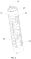
- the pipe wall thickness of the pipe body 18 is 0.3-1.0 mm; the surface height of the spiral diversion structure 11 is 1-5 mm; the thread spacing of the surface of the inner pipe 10 is 5-20 mm. In this embodiment, the surface height of the spiral diversion structure 11 is 1.8 mm, and the thread spacing is 6 mm.
- the spiral diversion structure 11 is used in cooperation with the outer pipe 20 sleeved outside the inner pipe 10 in the liquid heating apparatus.
- End covers 30 are sleeved at two ends of the inner pipe 10 respectively; the end covers 30 each include an end cover wall and an end cover face connected to the end cover wall; the end cover wall and the outer peripheral wall sealing of the inner pipe 10 are sealed and fixed by welding.
- Two ends of the flow path 12 are sealed by the sealing covers 40; the sealing covers 40 each include a sealing wall and a sealing face 41 connected to the sealing wall; the sealing wall and the outer peripheral wall of the outer pipe 20 are sealed and fixed by welding.
- the end cover 30 and the sealing cover 40 are used for sealing the inner pipe 10 and the outer pipe 20 respectively; the sealing structures of the inner pipe 10 and the outer pipe 20 are separately and independently processed to facilitate manufacturing; moreover, the sealing effect is good, to improve the stability of the liquid heating apparatus in a high temperature and high pressure environment for a long time.
- the end cover 30, the sealing cover 40, the inner pipe 10, and the outer pipe 20 are all made of a stainless steel material, facilitating the fixedly welding therebetween.
- the embodiment provided by the present invention proves, through a large amount of experiments, that when the radical clearance is set in the range of 0.1-0.6 mm, the liquid can be fully heated, the heating effect is good, and it can be further ensured that the liquid flows smoothly while excessive heating of the liquid is avoided, and the generation of large bubbles can be prevented.
- the openings at the two ends of the inner pipe 10 are each provided with the expanded port 13; the expanded port 13 extends from a direction of the outer peripheral wall of the pipe body 18 away from the opening; and the expanded port 13 and the outer peripheral wall of the pipe body 18 can be integrated by welding or through the mold.
- the expanded port 13 and the pipe body 18 are integrated made through the mold; the sealing performance is good and the structure is stable; and after high temperature heating for a long time, the structure does not fall off.
- the inner pipe 10 is first sleeved into the outer pipe 20; the two ends of the inner pipe 10 and the outer pipe 20 are kept flush, and then the expanded ports 13 at the two ends of the inner pipe 10 are welded and fixed to the inner peripheral wall of the outer pipe 20, to implement the sealing of the flow path 12.
- the pipe body 18 and the expanded port 13 are both made of 304 stainless steel, have corrosion resistance, heat resistance, and good mechanical properties; the room temperature machining performance is relatively good, and erosion by a food processing medium can be resisted.
- the liquid is in directly contact with the inner pipe 10; 304 stainless steel material is not prone to rust and harmless to human body. Under the condition of long-term high temperature and high pressure, the phenomenon of blocking the flow path 12 caused by aging and bubbling of the plastic, rubber, and other materials due to heating is avoided. More importantly, unpleasant odor generated and toxic substances decomposed by long time heating of the plastic and rubber are avoided; and liquid can be rapidly heated, improving the use safety of the heated liquid and the service life of this liquid heating apparatus.
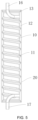
- a first through hole 15 penetrating a pipe wall of the pipe body 18 is disposed at a start position of the spiral diversion structure 11, so that the first through hole 15 communicates with the inner peripheral wall and the outer peripheral wall of the pipe body 18, and a flow path 12 inlet is formed at a joint between the first through hole 15 and the inner peripheral wall of the pipe body 18; and a second through hole 14 penetrating the pipe wall of the pipe body 18 is disposed at an end position of the spiral diversion structure 11, so that the second through hole 14 communicates with the inner peripheral wall and the outer peripheral wall of the pipe body 18, and a flow path 12 outlet is formed at a joint between the second through hole 14 and the inner peripheral wall of the pipe body 18.
- the flow path 12 inlet or flow path 12 outlet is disposed at the start position and end position of the spiral diversion structure 11 to communicate with the inner peripheral wall and outer peripheral wall of the pipe body 18; moreover, a certain distance from the end of the inner pipe 10 exists, so that the liquid may fully fill the flow path 12 for fully heating.
- the liquid inlet pipe 17 or liquid outlet pipe 16 is located at the inner peripheral wall of the inner pipe 10, extends in a direction from the liquid inlet 43 or liquid outlet 42 towards the openings of the two ends of the inner pipe 10, and is exposed at the openings at the two ends of the inner pipe 10.
- the liquid inlet pipe 17 or liquid outlet pipe 16 is disposed inside the inner pipe 10, which does not increase the volume of this liquid heating apparatus, and can be directly applied to the existing housing, facilitating machining and manufacturing. Moreover, there is a certain angle between the inlet of the liquid inlet pipe 17 or the outlet of the liquid outlet pipe 16 and the flow path 12 inlet or flow path 12 outlet, avoiding that the liquid cannot fully fill the flow path 12 to cause insufficient heating.
- the heating assembly 21 integrated at the outer peripheral wall of the outer pipe 20 heats the flowing liquid while the liquid to be heated flows along the flow path 12.
- the heat energy generated by the heating assembly 21 exchanges heat with the liquid in the flow path 12 to implement continuous heating of the liquid.
- a water pump (not shown in the figure) is disposed at the inlet of the liquid inlet pipe 17 to continuously deliver pressurized liquid into the flow path 12.
- the diameter of the second through hole 14 is smaller than that of the first through hole 15, to keep the liquid pressure in the flow path 12 between the liquid inlet pipe 17 and the liquid outlet pipe 16 at 0.1-1.0 MPa.
- the heating assembly 21 is disposed at the outer peripheral wall on the outer pipe 20.
- the heating assembly 21 includes an insulating medium layer disposed on the outer peripheral wall of the outer pipe 20 and a heating circuit 22 disposed at the insulating medium layer; the insulating medium layer is printed and burned on the outer peripheral wall of the outer pipe 20; and the heat energy generated by the heating circuit 22 is used for heat exchange with the liquid flowing in the flow path 12.
- the heating circuit 22 includes a plurality of heating resistors and electrodes 24 fixed to the insulating medium layer. The extending direction of each heating resistor is consistent with the length direction of the outer pipe 20. Two ends of the heating resistor are respectively and electrically connected to the electrode 24. In this way, a power source is connected at the electrode 24 for the heating resistor to generate heat energy.
- the PCB controls the water pump liquid inlet rate and/or the heating power of the heating resistor according to temperature information issued from a first temperature sensor 23.
- the temperature sensor 23 is disposed at the position close to the liquid outlet 42 and away from the heating resistor as far as possible, so as to accurately detect the temperature of the liquid at the liquid outlet 42.
- the temperature sensor 23 is configured to detect the outlet liquid temperature and provide a feedback to the PCB.
- the PCB automatically adjusts the heating power of the heating resistor according to the comparison between the actually measured outlet liquid temperature data and the temperature required by liquid outflow and set by the user, or controls the water pump to adjust the flow rate of the liquid entering the flow path 12, so as to further implement accurate control over the outlet liquid temperature.
- the plurality of heating resistors are distributed around the outer peripheral wall of the outer pipe 20, and are preferably distributed approximately uniformly, so that the heating resistor faces the liquid in the flow path 12 to transfer heat energy to the flowing liquid in time.
- the present invention further provides a method for preparing a liquid heating apparatus, where the method is used to prepare the liquid heating apparatus described above and includes the following steps.
- S1 Prepare a mold according to preset parameters of an inner pipe 10, place the mold into a pressure device, and set parameters and debug the device, where the preset parameters include a pipe wall thickness of an inner pipe 10, a height of an expanded port 13, and a height and a spacing and a spiral diversion structure 11; and the inner pipe 10 pipe wall thickness is 0.3-1.0 mm, the surface height of the spiral diversion structure 11 at the outer peripheral wall of the inner pipe 10 is 1-5 mm, and the thread spacing is 5-20 mm.
- S2 Place a metal material or a metal alloy material into the mold, and seal and lock the mold; and anneal the metal material or metal alloy material to lower the rigidity of the metal material or the metal alloy material.
- 304 stainless steel is selected in this embodiment, and has corrosion resistance, heat resistance, and good mechanical properties; moreover, the room temperature machining performance is relatively good, and erosion by food and a processing medium can be resisted.
- S3 Start the pressure device, and perform push wave forming by using a highpressure water drum, to complete machining, specifically including: using pressure to pressurize liquid in a limited space of the mold, and deforming the material by water pressure to make the material close to the mold shape, and integrally forming the spiral diversion structure 11 with the pipe body 18.
- This liquid heating apparatus is manufactured by using this method.
- the inner pipe 10 made of the stainless steel material, the spiral diversion structure 11 is formed at the pipe body 18 by using the inner pipe 10 through water rising of the mold. This avoids the aging, unsafety, ease of falling off from the inner pipe 10, and other problems that are prone to occur when the diversion structure is separately added to the conventional heating apparatus, the manufacturing cost is reduced, machining for many times is not needed, and the cost is low.
- the expanded ports 13 are disposed at the openings at the two ends of the inner pipe 10.
- the inner pipe 10 is welded to the outer pipe 20 through the expanded ports 13, to implement the sealing of the flow path 12.
- the formed liquid heating apparatus is simple to assemble, has a good sealing effect, and meets mass industrial production, and the stability of the liquid heating apparatus in the high temperature and high pressure environment for a long time is improved.
Landscapes
- Engineering & Computer Science (AREA)
- Mechanical Engineering (AREA)
- Physics & Mathematics (AREA)
- Thermal Sciences (AREA)
- Chemical & Material Sciences (AREA)
- Combustion & Propulsion (AREA)
- General Engineering & Computer Science (AREA)
- Food Science & Technology (AREA)
- Fluid Mechanics (AREA)
- Instantaneous Water Boilers, Portable Hot-Water Supply Apparatuses, And Control Of Portable Hot-Water Supply Apparatuses (AREA)
Claims (10)
- Innenrohr (10) für eine Flüssigkeitsheizvorrichtung, umfassend einen hohlen Rohrkörper (18), der aus einem Metall oder einer Legierung hergestellt ist, wobei eine Rohrwanddicke des Rohrkörpers 0,3-1. 0 mm beträgt; wobei durch ein Bearbeitungsverfahren des Walzens oder Pressens eine spiralförmige Umlenkstruktur (11) an einer inneren Umfangswand des Rohrkörpers entlang einer axialen Richtung des Rohrkörpers bearbeitet wird, so dass die spiralförmige Umlenkstruktur so ausgebildet ist, dass sie sich entlang der axialen Richtung des Rohrkörpers erstreckt, an einer äußeren Umfangswand des Rohrkörpers vorsteht und an der inneren Umfangswand versenkt ist,
wobei:das Innenrohr (10) außerdem erweiterte Öffnungen (13) aufweist, die an zwei Enden des Rohrkörpers angeordnet und in den Rohrkörper integriert sind,auf der inneren Umfangswand des Rohrkörpers ein erstes Durchgangsloch (15), das eine Rohrwand des Rohrkörpers durchdringt, an einer Startposition der spiralförmigen Umlenkstruktur angeordnet ist, so dass das erste Durchgangsloch mit der inneren Umfangswand und der äußeren Umfangswand des Rohrkörpers in Verbindung steht, und ein Strömungspfadeinlass an einer Verbindung zwischen dem ersten Durchgangsloch und der inneren Umfangswand des Rohrkörpers ausgebildet ist; und ein zweites Durchgangsloch (14), das die Rohrwand des Rohrkörpers durchdringt, an einer Endposition der spiralförmigen Umlenkstruktur angeordnet ist, so dass das zweite Durchgangsloch mit der inneren Umfangswand und der äußeren Umfangswand des Rohrkörpers in Verbindung steht und ein Strömungspfadauslass an einer Verbindung zwischen dem zweiten Durchgangsloch und der inneren Umfangswand des Rohrkörpers ausgebildet ist. - Innenrohr (10) nach Anspruch 1, wobei eine Oberflächenhöhe der spiralförmigen Umlenkstruktur, die an der äußeren Umfangswand des Rohrkörpers vorsteht, 1-5 mm und ein Gewindeabstand 5-20 mm beträgt.
- Flüssigkeitsheizvorrichtung, umfassend:Innenrohr nach Anspruch 1, wobei Öffnungen an zwei Enden des Innenrohrs durch Endabdeckungen (30) aus einem Metallmaterial verschlossen sind; undein Außenrohr (20), wobei eine innere Umfangswand des Außenrohrs von einem höchsten Punkt der spiralförmigen Umlenkstruktur um einen vorbestimmten radialen Abstand beabstandet ist, so dass das Außenrohr an einem äußeren Teil der spiralförmigen Umlenkstruktur ummantelt ist; und wobei eine Heizanordnung (21) an der äußeren Umfangswand des Außenrohrs angeordnet ist;wobei das Innenrohr, das Außenrohr und die spiralförmige Umlenkstruktur einen Strömungspfad bilden; Öffnungen an zwei Enden des Strömungspfads durch Dichtungsabdeckungen (40) abgedichtet sind; die Dichtungsabdeckung mit einem Flüssigkeitsauslass (42) oder einem Flüssigkeitseinlass (43) versehen ist; und wobei Flüssigkeit durch den Flüssigkeitseinlass der Dichtungsabdeckung zum Erwärmen in den Strömungspfad eintritt und aus dem Flüssigkeitsauslass abgeleitet wird.
- Flüssigkeitsheizvorrichtung, umfassend:das Innenrohr nach Anspruch 1 oder 2; undein Außenrohr, wobei eine innere Umfangswand des Außenrohrs von einem höchsten Punkt der spiralförmigen Umlenkstruktur um einen vorbestimmten radialen Abstand beabstandet ist, so dass das Außenrohr an einem äußeren Teil der spiralförmigen Umlenkstruktur ummantelt ist; und wobei eine Heizanordnung an der äußeren Umfangswand des Außenrohrs angeordnet ist;Wobei das Innenrohr, das Außenrohr und die spiralförmige Umlenkstruktur einen Strömungspfad bilden; Öffnungen an zwei Enden des Strömungspfads durch erweiterte Öffnungen abgedichtet sind.
- Flüssigkeitsheizvorrichtung nach Anspruch 4, wobei ein Flüssigkeitseinlassrohr an einem Einlass des Strömungspfads angeordnet ist; ein Flüssigkeitsauslassrohr an einem Auslass des Strömungspfads angeordnet ist; und wobei sich das Flüssigkeitseinlassrohr oder das Flüssigkeitsauslassrohr durch das erste Durchgangsloch oder das zweite Durchgangsloch in Richtung der Öffnungen der beiden Enden des Innenrohrs erstreckt und an den Öffnungen an den beiden Enden des Innenrohrs freiliegt.
- Flüssigkeitsheizvorrichtung nach Anspruch 5, wobei die erweiterte Öffnung mit einem Ende des Außenrohrs verschweißt und abgedichtet ist; und das Flüssigkeitseinlassrohr oder das Flüssigkeitsauslassrohr mit dem ersten Durchgangsloch oder dem zweiten Durchgangsloch verschweißt ist.
- Flüssigkeitsheizvorrichtung nach Anspruch 3 oder 6, umfassend eine Wasserpumpe, wobei das Flüssigkeitseinlassrohr mit der Wasserpumpe verbunden ist und der Durchmesser des Flüssigkeitsauslassrohrs nicht größer als der Durchmesser des Flüssigkeitseinlassrohrs ist, um den Flüssigkeitsdruck im Strömungspfad auf 0,1-1,0 MPa zu halten.
- Flüssigkeitsheizvorrichtung nach Anspruch 6, wobei das Innenrohr und die erweiterte Öffnung beide aus einem rostfreien Stahlmaterial bestehen.
- Flüssigkeitsheizvorrichtung nach Anspruch 7, ferner umfassend einen Temperatursensor (23) und eine Steuerung, die elektrisch mit dem Temperatursensor verbunden ist, wobei der Temperatursensor an einer Stelle des Außenrohrs in der Nähe des zweiten Durchgangslochs angeordnet ist und die Steuerung so konfiguriert ist, dass sie entsprechend der vom Temperatursensor ausgegebenen Temperaturinformation die Flüssigkeitseinlassgeschwindigkeit der Wasserpumpe und/oder die Heizleistung der Heizanordnung steuert.
- Verfahren zur Herstellung einer Flüssigkeitsheizvorrichtung, wobei das Verfahren zur Herstellung der Flüssigkeitsheizvorrichtung nach einem der Ansprüche 4 bis 9 verwendet wird und die folgenden Schritte umfasst:S1: Vorbereiten einer Form gemäß den voreingestellten Parametern eines Innenrohrs und Einbringen der Form in einer Druckvorrichtung; und Einstellen von Parametern und Prüfen der Vorrichtung, wobei der voreingestellte Parameter eine Innenrohrdicke, eine Höhe einer erweiterten Öffnung und eine Höhe und einen Abstand einer spiralförmigen Umlenkstruktur umfasst;S2: Einbringen eines Metallmaterials oder einer Metalllegierung in die Form; Abdichten und Verschließen der Form; und Glühen des Metallmaterials oder der Metalllegierung;S3: Starten der Druckvorrichtung, Ausführen einer Druckwellenformung unter Verwendung einer Hochdruckwassertrommel, um die Bearbeitung abzuschließen, und Integrieren der spiralförmigen Umlenkstruktur in einen Rohrkörper;S4: Entlasten des Drucks und Lösen der Form und Entnehmen des vorbereiteten Innenrohrs; undS5: Ummanteln des Innenrohrs mit einem Außenrohr, so dass der Abstand zwischen dem höchsten Punkt des Innenrohrs und dem Außenrohr 0,1-0,6 mm beträgt; Ausrichten von zwei Enden des Innenrohrs und des Außenrohrs; und Verschweißen einer Öffnung, um eine Abdichtung zu erreichen.
Applications Claiming Priority (2)
| Application Number | Priority Date | Filing Date | Title |
|---|---|---|---|
| CN201911365384.6A CN111102735A (zh) | 2019-12-26 | 2019-12-26 | 用于液体加热装置的内管及液体加热装置、制造方法 |
| PCT/CN2020/139249 WO2021129785A1 (zh) | 2019-12-26 | 2020-12-25 | 用于液体加热装置的内管及液体加热装置、制造方法 |
Publications (4)
| Publication Number | Publication Date |
|---|---|
| EP4080132A1 EP4080132A1 (de) | 2022-10-26 |
| EP4080132A4 EP4080132A4 (de) | 2023-01-25 |
| EP4080132B1 true EP4080132B1 (de) | 2024-08-07 |
| EP4080132C0 EP4080132C0 (de) | 2024-08-07 |
Family
ID=70425495
Family Applications (1)
| Application Number | Title | Priority Date | Filing Date |
|---|---|---|---|
| EP20904950.1A Active EP4080132B1 (de) | 2019-12-26 | 2020-12-25 | Inneres rohr für eine flüssigkeitsheizvorrichtung, und flüssigkeitsheizvorrichtung und produktionsverfahren dafür |
Country Status (4)
| Country | Link |
|---|---|
| US (1) | US20220316757A1 (de) |
| EP (1) | EP4080132B1 (de) |
| CN (1) | CN111102735A (de) |
| WO (1) | WO2021129785A1 (de) |
Families Citing this family (13)
| Publication number | Priority date | Publication date | Assignee | Title |
|---|---|---|---|---|
| CN111102735A (zh) * | 2019-12-26 | 2020-05-05 | 佛山市海德精工电子科技有限公司 | 用于液体加热装置的内管及液体加热装置、制造方法 |
| GB2595640A (en) | 2020-05-26 | 2021-12-08 | Edwards Vacuum Llc | Vacuum apparatus temperature sensor assembly |
| EP4167814B1 (de) * | 2020-06-19 | 2023-10-11 | Heylo S.R.L. | Getränkezubereitungsautomat mit elektromagnetischer induktion und durchlauferhitzer |
| CN114060287B (zh) * | 2020-08-07 | 2024-08-09 | 广东汉宇汽车配件有限公司 | 一种动力电池热管理系统用电泵 |
| CN112254837A (zh) * | 2020-10-10 | 2021-01-22 | 衢州学院 | 一种船用光纤光栅温度传感器及其使用方法 |
| CN112121216A (zh) * | 2020-10-20 | 2020-12-25 | 湖南幻影三陆零科技有限公司 | 一种加热装置 |
| CN115540355A (zh) * | 2022-02-21 | 2022-12-30 | 上海跨博电器有限公司 | 一种热水器用高效加热器 |
| CN114674076B (zh) * | 2022-03-18 | 2025-07-25 | 宁波西健医疗技术研究有限公司 | 一种灌注液体加热器及其控制方法 |
| CN115057602B (zh) * | 2022-06-09 | 2024-04-12 | 上海电气集团股份有限公司 | 一种干化器及其干化系统 |
| CN116546678B (zh) * | 2023-05-19 | 2025-12-05 | 宁波特为电器有限公司 | 一种即热式加热管及其加工方法 |
| WO2024250267A1 (zh) * | 2023-06-09 | 2024-12-12 | 深圳和而泰新材料科技有限公司 | 加热装置和热饮设备 |
| CN118362334B (zh) * | 2024-06-19 | 2024-10-18 | 江苏沃凯氟精密智造有限公司 | 一种液体加热器测试工装 |
| CN120489595B (zh) * | 2025-07-16 | 2025-09-05 | 江苏沃凯氟精密智造有限公司 | 一种流水式液体加热模块测试平台 |
Family Cites Families (23)
| Publication number | Priority date | Publication date | Assignee | Title |
|---|---|---|---|---|
| CN1123720C (zh) * | 2000-12-13 | 2003-10-08 | 梁世良 | 快速管接头及其制造方法 |
| CN201181172Y (zh) * | 2008-02-21 | 2009-01-14 | 广州泰菱科技研发有限公司 | 内管螺旋加强型套管式换热器 |
| CN102967043A (zh) * | 2011-08-30 | 2013-03-13 | 佛山市顺德昀陶设计有限公司 | 液体加热装置 |
| CN102636052A (zh) * | 2012-05-11 | 2012-08-15 | 江苏亚太轻合金科技股份有限公司 | 高效热交换同轴管 |
| US9970687B2 (en) * | 2013-06-26 | 2018-05-15 | Tai-Her Yang | Heat-dissipating structure having embedded support tube to form internally recycling heat transfer fluid and application apparatus |
| WO2014205771A1 (en) * | 2013-06-28 | 2014-12-31 | Nestec S.A. | Thick film heating device |
| US9943899B2 (en) * | 2014-03-25 | 2018-04-17 | Montebello Technology Services Ltd. | Method for blow molding metal containers |
| CN104259746A (zh) * | 2014-07-28 | 2015-01-07 | 李仁波 | 水龙头外壳的制作方法 |
| CN205279802U (zh) * | 2015-12-17 | 2016-06-01 | 英特换热设备(浙江)有限公司 | 一种加强型螺旋管高效换热器 |
| CN205481685U (zh) * | 2016-02-05 | 2016-08-17 | 赵伟 | 一种液体加热装置 |
| CN105546804B (zh) * | 2016-02-05 | 2019-03-22 | 佛山市云米电器科技有限公司 | 一种用于液体加热的加热装置 |
| KR101797176B1 (ko) * | 2016-03-21 | 2017-11-13 | 주식회사 평산 | 대체냉매적용 공조시스템의 내부 열교환기 이중관 구조 |
| WO2017200362A1 (en) * | 2016-05-20 | 2017-11-23 | Contitech Fluid Korea Ltd. | Double tube for heat-exchange |
| CN106903197B (zh) * | 2017-02-27 | 2018-07-03 | 哈尔滨工业大学 | 一种耐高压外胀式螺旋波纹管强化传热元件的制备方法及应用 |
| CN206959313U (zh) * | 2017-06-30 | 2018-02-02 | 重庆山外山血液净化技术股份有限公司 | 医用加热装置 |
| KR102403434B1 (ko) * | 2017-08-18 | 2022-05-27 | 조한용 | 이중 파이프 |
| CN108458474A (zh) * | 2018-02-05 | 2018-08-28 | 佛山市海德精工电子科技有限公司 | 一种液体加热装置 |
| CN108456474A (zh) * | 2018-03-13 | 2018-08-28 | 佛山市飞时达新材料科技有限公司 | 一种外墙防污涂料的制备方法及其应用 |
| CN209101545U (zh) * | 2018-09-03 | 2019-07-12 | 佛山市海德精工电子科技有限公司 | 一种液体加热装置 |
| CN109458729B (zh) * | 2018-11-01 | 2025-06-03 | 佛山市海德精工电子科技有限公司 | 管式厚膜加热器保护装置及管式厚膜加热器 |
| CN209512578U (zh) * | 2018-12-25 | 2019-10-18 | 江苏爱能洁新能源有限公司 | 一种换热管 |
| CN212339605U (zh) * | 2019-12-26 | 2021-01-12 | 佛山市海德精工电子科技有限公司 | 用于液体加热装置的内管及液体加热装置 |
| CN111102735A (zh) * | 2019-12-26 | 2020-05-05 | 佛山市海德精工电子科技有限公司 | 用于液体加热装置的内管及液体加热装置、制造方法 |
-
2019
- 2019-12-26 CN CN201911365384.6A patent/CN111102735A/zh active Pending
-
2020
- 2020-12-25 WO PCT/CN2020/139249 patent/WO2021129785A1/zh not_active Ceased
- 2020-12-25 EP EP20904950.1A patent/EP4080132B1/de active Active
-
2022
- 2022-06-24 US US17/808,558 patent/US20220316757A1/en active Pending
Also Published As
| Publication number | Publication date |
|---|---|
| WO2021129785A1 (zh) | 2021-07-01 |
| EP4080132A4 (de) | 2023-01-25 |
| EP4080132C0 (de) | 2024-08-07 |
| US20220316757A1 (en) | 2022-10-06 |
| CN111102735A (zh) | 2020-05-05 |
| EP4080132A1 (de) | 2022-10-26 |
Similar Documents
| Publication | Publication Date | Title |
|---|---|---|
| EP4080132B1 (de) | Inneres rohr für eine flüssigkeitsheizvorrichtung, und flüssigkeitsheizvorrichtung und produktionsverfahren dafür | |
| CN101795607B (zh) | 用于热饮生产机器的锅炉 | |
| KR101637210B1 (ko) | 히타를 사용한 슬림구조를 갖는 정수기의 온수공급을 위한 순간 가온기 | |
| CN111089282A (zh) | 家用电器的蒸汽发生器及其控制方法、蒸烤箱 | |
| WO2019148785A1 (zh) | 一种液体加热装置 | |
| CN102595985A (zh) | 加热器 | |
| KR20160099154A (ko) | 순간가열장치 | |
| CN110801157A (zh) | 一种液体加热装置 | |
| CN102933124B (zh) | 饮料分配机器 | |
| CN206582176U (zh) | 集成加热泵 | |
| KR100624568B1 (ko) | 세정기용 순간 온수장치 | |
| CN101568765B (zh) | 用于发生蒸汽的装置和方法 | |
| EP3141837B1 (de) | Wassererhitzer | |
| CN211748908U (zh) | 一种液体加热装置 | |
| WO2026016976A1 (zh) | 一种加热装置及其制作方法 | |
| CN212339605U (zh) | 用于液体加热装置的内管及液体加热装置 | |
| CN213882832U (zh) | 一种蒸汽烹饪设备 | |
| CN108477981B (zh) | 用于蒸汽烹饪装置的蒸汽锅炉 | |
| CN216619783U (zh) | 新型蒸汽发生器 | |
| CN209863492U (zh) | 一种加热效率高的蒸汽食品加工机 | |
| WO2016026097A1 (en) | Continuous-flow water heating assembly and production method | |
| CN209495301U (zh) | 一种可控蒸汽发生装置 | |
| CN209541145U (zh) | 管式厚膜加热器保护装置及管式厚膜加热器 | |
| CN208909837U (zh) | 蒸汽发生器 | |
| CN208822341U (zh) | 水路板组件、水路组件和蒸汽发生器 |
Legal Events
| Date | Code | Title | Description |
|---|---|---|---|
| STAA | Information on the status of an ep patent application or granted ep patent |
Free format text: STATUS: THE INTERNATIONAL PUBLICATION HAS BEEN MADE |
|
| PUAI | Public reference made under article 153(3) epc to a published international application that has entered the european phase |
Free format text: ORIGINAL CODE: 0009012 |
|
| STAA | Information on the status of an ep patent application or granted ep patent |
Free format text: STATUS: REQUEST FOR EXAMINATION WAS MADE |
|
| 17P | Request for examination filed |
Effective date: 20220719 |
|
| AK | Designated contracting states |
Kind code of ref document: A1 Designated state(s): AL AT BE BG CH CY CZ DE DK EE ES FI FR GB GR HR HU IE IS IT LI LT LU LV MC MK MT NL NO PL PT RO RS SE SI SK SM TR |
|
| A4 | Supplementary search report drawn up and despatched |
Effective date: 20230102 |
|
| RIC1 | Information provided on ipc code assigned before grant |
Ipc: F24H 1/16 20220101ALN20221220BHEP Ipc: C21D 1/00 20060101ALI20221220BHEP Ipc: B21D 53/06 20060101ALI20221220BHEP Ipc: B21D 15/10 20060101ALI20221220BHEP Ipc: A47J 31/54 20060101ALI20221220BHEP Ipc: F24H 9/20 20220101ALI20221220BHEP Ipc: F24H 15/219 20220101ALI20221220BHEP Ipc: F24H 15/37 20220101ALI20221220BHEP Ipc: F24H 15/34 20220101ALI20221220BHEP Ipc: F24H 15/174 20220101ALI20221220BHEP Ipc: H05B 3/42 20060101ALI20221220BHEP Ipc: F24H 9/1818 20220101ALI20221220BHEP Ipc: F24H 1/12 20220101ALI20221220BHEP Ipc: F24H 9/00 20220101ALI20221220BHEP Ipc: F24H 1/10 20220101AFI20221220BHEP |
|
| DAV | Request for validation of the european patent (deleted) | ||
| DAX | Request for extension of the european patent (deleted) | ||
| STAA | Information on the status of an ep patent application or granted ep patent |
Free format text: STATUS: EXAMINATION IS IN PROGRESS |
|
| 17Q | First examination report despatched |
Effective date: 20230929 |
|
| GRAP | Despatch of communication of intention to grant a patent |
Free format text: ORIGINAL CODE: EPIDOSNIGR1 |
|
| STAA | Information on the status of an ep patent application or granted ep patent |
Free format text: STATUS: GRANT OF PATENT IS INTENDED |
|
| RIC1 | Information provided on ipc code assigned before grant |
Ipc: F24H 1/16 20220101ALN20240219BHEP Ipc: H05B 3/46 20060101ALI20240219BHEP Ipc: H05B 1/02 20060101ALI20240219BHEP Ipc: C21D 1/00 20060101ALI20240219BHEP Ipc: B21D 53/06 20060101ALI20240219BHEP Ipc: B21D 15/10 20060101ALI20240219BHEP Ipc: A47J 31/54 20060101ALI20240219BHEP Ipc: F24H 9/20 20220101ALI20240219BHEP Ipc: F24H 15/219 20220101ALI20240219BHEP Ipc: F24H 15/37 20220101ALI20240219BHEP Ipc: F24H 15/34 20220101ALI20240219BHEP Ipc: F24H 15/174 20220101ALI20240219BHEP Ipc: H05B 3/42 20060101ALI20240219BHEP Ipc: F24H 9/1818 20220101ALI20240219BHEP Ipc: F24H 1/12 20220101ALI20240219BHEP Ipc: F24H 9/00 20220101ALI20240219BHEP Ipc: F24H 1/10 20220101AFI20240219BHEP |
|
| INTG | Intention to grant announced |
Effective date: 20240311 |
|
| GRAS | Grant fee paid |
Free format text: ORIGINAL CODE: EPIDOSNIGR3 |
|
| GRAA | (expected) grant |
Free format text: ORIGINAL CODE: 0009210 |
|
| STAA | Information on the status of an ep patent application or granted ep patent |
Free format text: STATUS: THE PATENT HAS BEEN GRANTED |
|
| AK | Designated contracting states |
Kind code of ref document: B1 Designated state(s): AL AT BE BG CH CY CZ DE DK EE ES FI FR GB GR HR HU IE IS IT LI LT LU LV MC MK MT NL NO PL PT RO RS SE SI SK SM TR |
|
| REG | Reference to a national code |
Ref country code: GB Ref legal event code: FG4D |
|
| REG | Reference to a national code |
Ref country code: CH Ref legal event code: EP |
|
| REG | Reference to a national code |
Ref country code: IE Ref legal event code: FG4D |
|
| REG | Reference to a national code |
Ref country code: DE Ref legal event code: R096 Ref document number: 602020035550 Country of ref document: DE |
|
| U01 | Request for unitary effect filed |
Effective date: 20240821 |
|
| U07 | Unitary effect registered |
Designated state(s): AT BE BG DE DK EE FI FR IT LT LU LV MT NL PT RO SE SI Effective date: 20240902 |
|
| PG25 | Lapsed in a contracting state [announced via postgrant information from national office to epo] |
Ref country code: NO Free format text: LAPSE BECAUSE OF FAILURE TO SUBMIT A TRANSLATION OF THE DESCRIPTION OR TO PAY THE FEE WITHIN THE PRESCRIBED TIME-LIMIT Effective date: 20241107 |
|
| PG25 | Lapsed in a contracting state [announced via postgrant information from national office to epo] |
Ref country code: PL Free format text: LAPSE BECAUSE OF FAILURE TO SUBMIT A TRANSLATION OF THE DESCRIPTION OR TO PAY THE FEE WITHIN THE PRESCRIBED TIME-LIMIT Effective date: 20240807 Ref country code: GR Free format text: LAPSE BECAUSE OF FAILURE TO SUBMIT A TRANSLATION OF THE DESCRIPTION OR TO PAY THE FEE WITHIN THE PRESCRIBED TIME-LIMIT Effective date: 20241108 |
|
| PG25 | Lapsed in a contracting state [announced via postgrant information from national office to epo] |
Ref country code: IS Free format text: LAPSE BECAUSE OF FAILURE TO SUBMIT A TRANSLATION OF THE DESCRIPTION OR TO PAY THE FEE WITHIN THE PRESCRIBED TIME-LIMIT Effective date: 20241207 |
|
| PG25 | Lapsed in a contracting state [announced via postgrant information from national office to epo] |
Ref country code: HR Free format text: LAPSE BECAUSE OF FAILURE TO SUBMIT A TRANSLATION OF THE DESCRIPTION OR TO PAY THE FEE WITHIN THE PRESCRIBED TIME-LIMIT Effective date: 20240807 |
|
| PG25 | Lapsed in a contracting state [announced via postgrant information from national office to epo] |
Ref country code: RS Free format text: LAPSE BECAUSE OF FAILURE TO SUBMIT A TRANSLATION OF THE DESCRIPTION OR TO PAY THE FEE WITHIN THE PRESCRIBED TIME-LIMIT Effective date: 20241107 Ref country code: ES Free format text: LAPSE BECAUSE OF FAILURE TO SUBMIT A TRANSLATION OF THE DESCRIPTION OR TO PAY THE FEE WITHIN THE PRESCRIBED TIME-LIMIT Effective date: 20240807 |
|
| PG25 | Lapsed in a contracting state [announced via postgrant information from national office to epo] |
Ref country code: RS Free format text: LAPSE BECAUSE OF FAILURE TO SUBMIT A TRANSLATION OF THE DESCRIPTION OR TO PAY THE FEE WITHIN THE PRESCRIBED TIME-LIMIT Effective date: 20241107 Ref country code: PL Free format text: LAPSE BECAUSE OF FAILURE TO SUBMIT A TRANSLATION OF THE DESCRIPTION OR TO PAY THE FEE WITHIN THE PRESCRIBED TIME-LIMIT Effective date: 20240807 Ref country code: NO Free format text: LAPSE BECAUSE OF FAILURE TO SUBMIT A TRANSLATION OF THE DESCRIPTION OR TO PAY THE FEE WITHIN THE PRESCRIBED TIME-LIMIT Effective date: 20241107 Ref country code: IS Free format text: LAPSE BECAUSE OF FAILURE TO SUBMIT A TRANSLATION OF THE DESCRIPTION OR TO PAY THE FEE WITHIN THE PRESCRIBED TIME-LIMIT Effective date: 20241207 Ref country code: HR Free format text: LAPSE BECAUSE OF FAILURE TO SUBMIT A TRANSLATION OF THE DESCRIPTION OR TO PAY THE FEE WITHIN THE PRESCRIBED TIME-LIMIT Effective date: 20240807 Ref country code: GR Free format text: LAPSE BECAUSE OF FAILURE TO SUBMIT A TRANSLATION OF THE DESCRIPTION OR TO PAY THE FEE WITHIN THE PRESCRIBED TIME-LIMIT Effective date: 20241108 Ref country code: ES Free format text: LAPSE BECAUSE OF FAILURE TO SUBMIT A TRANSLATION OF THE DESCRIPTION OR TO PAY THE FEE WITHIN THE PRESCRIBED TIME-LIMIT Effective date: 20240807 |
|
| U20 | Renewal fee for the european patent with unitary effect paid |
Year of fee payment: 5 Effective date: 20241227 |
|
| PG25 | Lapsed in a contracting state [announced via postgrant information from national office to epo] |
Ref country code: SM Free format text: LAPSE BECAUSE OF FAILURE TO SUBMIT A TRANSLATION OF THE DESCRIPTION OR TO PAY THE FEE WITHIN THE PRESCRIBED TIME-LIMIT Effective date: 20240807 |
|
| PGFP | Annual fee paid to national office [announced via postgrant information from national office to epo] |
Ref country code: CH Payment date: 20250101 Year of fee payment: 5 |
|
| PG25 | Lapsed in a contracting state [announced via postgrant information from national office to epo] |
Ref country code: CZ Free format text: LAPSE BECAUSE OF FAILURE TO SUBMIT A TRANSLATION OF THE DESCRIPTION OR TO PAY THE FEE WITHIN THE PRESCRIBED TIME-LIMIT Effective date: 20240807 |
|
| PG25 | Lapsed in a contracting state [announced via postgrant information from national office to epo] |
Ref country code: SK Free format text: LAPSE BECAUSE OF FAILURE TO SUBMIT A TRANSLATION OF THE DESCRIPTION OR TO PAY THE FEE WITHIN THE PRESCRIBED TIME-LIMIT Effective date: 20240807 |
|
| PLBE | No opposition filed within time limit |
Free format text: ORIGINAL CODE: 0009261 |
|
| STAA | Information on the status of an ep patent application or granted ep patent |
Free format text: STATUS: NO OPPOSITION FILED WITHIN TIME LIMIT |
|
| PG25 | Lapsed in a contracting state [announced via postgrant information from national office to epo] |
Ref country code: MC Free format text: LAPSE BECAUSE OF FAILURE TO SUBMIT A TRANSLATION OF THE DESCRIPTION OR TO PAY THE FEE WITHIN THE PRESCRIBED TIME-LIMIT Effective date: 20240807 |
|
| 26N | No opposition filed |
Effective date: 20250508 |
|
| PG25 | Lapsed in a contracting state [announced via postgrant information from national office to epo] |
Ref country code: IE Free format text: LAPSE BECAUSE OF NON-PAYMENT OF DUE FEES Effective date: 20241225 |
|
| REG | Reference to a national code |
Ref country code: CH Ref legal event code: U11 Free format text: ST27 STATUS EVENT CODE: U-0-0-U10-U11 (AS PROVIDED BY THE NATIONAL OFFICE) Effective date: 20260101 |
|
| PGFP | Annual fee paid to national office [announced via postgrant information from national office to epo] |
Ref country code: GB Payment date: 20251126 Year of fee payment: 6 |
|
| U20 | Renewal fee for the european patent with unitary effect paid |
Year of fee payment: 6 Effective date: 20251224 |