EP4079983B1 - Hebestation für abwasser mit verstärktem boden - Google Patents
Hebestation für abwasser mit verstärktem boden Download PDFInfo
- Publication number
- EP4079983B1 EP4079983B1 EP22161893.7A EP22161893A EP4079983B1 EP 4079983 B1 EP4079983 B1 EP 4079983B1 EP 22161893 A EP22161893 A EP 22161893A EP 4079983 B1 EP4079983 B1 EP 4079983B1
- Authority
- EP
- European Patent Office
- Prior art keywords
- tank
- peripheral wall
- pumping station
- base
- central axis
- Prior art date
- Legal status (The legal status is an assumption and is not a legal conclusion. Google has not performed a legal analysis and makes no representation as to the accuracy of the status listed.)
- Active
Links
Images


Classifications
-
- E—FIXED CONSTRUCTIONS
- E03—WATER SUPPLY; SEWERAGE
- E03F—SEWERS; CESSPOOLS
- E03F5/00—Sewerage structures
- E03F5/22—Adaptations of pumping plants for lifting sewage
Definitions
- the field of the invention is that of the design and manufacture of wastewater treatment equipment. More specifically, the invention relates to a pumping station for a sanitation network, of the type comprising a prefabricated tank intended to be buried, and a pump intended to be placed in the tank.
- Pumping station tanks typically have a bottom and a peripheral wall that extends from the bottom to an opening.
- Such tanks take, for example, a cylindrical shape of revolution.
- a lifting pump is placed at the bottom of the tank and pumps the collected water.
- a pumping station tank can be built directly on its installation site, and is for example masonry.
- a pumping station tank can also be prefabricated. That is to say, this tank is manufactured in a factory and designed to be able to be moved to the site of its installation. This method of manufacturing and installation is more economical and quicker to carry out.
- Installing a pumping station then involves digging a pit at least the size of the tank, then inserting the prefabricated tank into the pit. Then, a backfill material is poured around the tank to wedge it inside the pit.
- These prefabricated tanks can be made of concrete or plastic (for example polyethylene or polyester resin reinforced with glass fibers).
- Prefabricated plastic tanks are easier to move and install than their concrete counterparts. However, they have disadvantages inherent in the nature of the material they are made of.
- a first problem relates to the external pressure to which these tanks can be subjected.
- the pit housing the tank may be submerged and, in this case, the submersion water exerts pressure on the tank likely to deform it or even lift it.
- a particular disadvantage of this problem is the deformation of the tank bottom. Since the pump of the lifting station rests on the tank bottom, this deformation causes the pump to move, which can cause damage to the lifting station.
- the pump is often inserted inside a tank by means of guides descending inside the tank, and the pump is coupled to a water evacuation network by means of a pipe penetrating inside the tank and descending to this pump.
- a second problem relates to the phenomenon of reservoirs being unearthed.
- Plastic tanks being lightweight by nature, are particularly prone to this problem.
- the filling is adapted to improve their buried maintenance.
- the tank inserted into the pit can be wedged and held in position by pouring a concrete belt, and possibly by pouring a concrete slab above the tank.
- the invention aims in particular to overcome the drawbacks of the prior art.
- the invention aims to propose a sewage network pumping station which is easy to install and which has a robust design, in particular in that it can withstand the stresses generated by a submersion situation.
- the invention also aims to provide such a station whose tank has the capacity to withstand the pressures to which it may be subjected, and which has the capacity to remain at the bottom of a pit in which it is buried.
- plastic material means, for example, materials such as polyethylene, polypropylene or a hardened plastic resin reinforced with a reinforcement, for example with glass fibres or carbon fibres.
- the plastic material tank is prefabricated in the factory and is lightweight compared to a prefabricated concrete tank.
- the pumping station has a reinforced bottom capable of better resisting the stresses exerted on the bottom when the pumping station is installed, and improving the capacity of the tank to remain buried despite external stresses likely to cause the tank to be lifted from the pit in which it was buried.
- This design helps reduce the impact of forces that could deform the bottom of the pumping station tank.
- the filling materials used to fill the pit in which the tank was positioned exert a force against the wall of the base, towards the bottom, and reinforce the maintenance of the tank in the pit.
- the partition has a central stiffening rib having an external edge extending from the bottom away from the central axis to the peripheral wall.
- stiffening ribs contribute to the diffusion of stresses exerted on the bottom towards the peripheral wall.
- stiffening ribs improve the structural strength of the bulkhead extending from each notch.
- the peripheral wall has at least one longitudinal protrusion extending parallel to the central axis from a lower end to a higher end of the peripheral wall, the longitudinal protrusions having a longitudinal flat which extends from the lower end to the higher end of the peripheral wall.
- these longitudinal protrusions can be easily pierced to be crossed by a pipe whose passage through the peripheral wall by the longitudinal flat can be effectively sealed using a seal, the surface crossed being flat.
- the peripheral wall has two main longitudinal outgrowths above the notches, the edge of the central stiffening rib which extends from the notch connecting to the main longitudinal outgrowth above.
- the peripheral wall has two intermediate longitudinal outgrowths, the longitudinal outgrowths being regularly distributed around the peripheral wall, and the tank has for each intermediate longitudinal outgrowth a stiffening rib connecting the intermediate longitudinal outgrowth to the base.
- the upper truncated cone-shaped portions serve to form faces against which the filling material, used to fill the pit in which the tank is buried, comes to bear and exerts a force towards the bottom, thereby improving the retention of the tank at the bottom of the pit.
- the corrugations thus reinforce the capacity of the tank to be effectively maintained in place in the place where it is buried.
- the upper truncated portion extends over a height along the central axis that is lower than the lower truncated portion.
- the angle formed by the upper frustoconical portion with a horizontal plane, in a cross-sectional view, is smaller than that formed by the lower frustoconical portion with a horizontal plane. This enhances the ability of the upper frustoconical portions to improve the retention of the tank at the bottom of the pit, by means of the backfill material, while the lower frustoconical portion has the function of spacing the upper frustoconical portions and providing a large reception volume above the upper frustoconical portions.
- the tank comprises an internal ballast placed in the base, the internal ballast having a reservation for receiving the pump on the central location of the bottom.
- the tank has a greater capacity to remain buried, thanks to its ballast, and the installation of the ballasted tank is particularly simple. Indeed, in a situation where a concrete surround of a tank according to the prior art is necessary, the tank according to the invention may not require one.
- the reservation concentrates the water collected in the tank at the level of the lifting pump.
- the internal ballast is molded into the base.
- the internal ballast then takes an optimized shape above the bottom and in the base.
- the pumping station comprises a manhole riser, the riser having a complementary threaded cylindrical body screwed into an internal thread presented by the tank at its opening.
- the cylindrical body has predetermined drilling locations, these locations having recesses each comprising a flat face set back from an external thread presented by the threaded cylindrical body.
- the water drainage networks being, according to the regulations in force, at predetermined depths in relation to the surface of a ground, then the presence of the drilling locations along the cylindrical body of the manhole riser allows easy connection of the drainage network to the tank of the pumping station.
- the lifting station comprises a reinforcement plate coupled to a lower face of the bottom of the tank.
- This reinforcement plate helps to strengthen the base against stresses that could deform it.
- This reinforcement plate can take the shape of the bottom, or take the shape of a disc.
- the reinforcement plate can be coupled for example by welding or gluing.
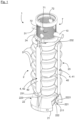
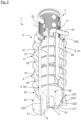
- a sewage network pumping station 1 In reference to the figures 1 And 2 , a sewage network pumping station 1, according to the invention, is shown.
- Station 1 includes a tank 2 which is designed to be buried.
- This tank 2 is intended to collect water to allow it to be returned to a height greater than that at which it is collected.
- Tank 2 is molded from a plastic material, and is preferably polyethylene.
- the tank 2 has a bottom 21, a peripheral wall 23, and an opening 24.
- the peripheral wall 23 extends along a central axis C ( figure 5 ).
- the tank 2 also has a base 22 which integrates the bottom 21 of the tank 2.
- the peripheral wall 23 adopts a shape having a cross-section to the central axis C which is essentially oval, this shape being able to fit into a cylinder of revolution.
- a pipe 10 for supplying water to be raised is shown.
- This pipe 10 opens into the interior of the tank 2. Through this pipe 10, water to be raised flows into the interior of the tank 2.
- pump 3 is intended to be centered on the central C axis.
- Station 1 also includes a water lifting pipe 31 which extends from pump 3, parallel to the central axis C and then opens outside tank 2.
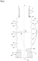
- Tank 2 is described in more detail below with reference to figures 1 , 2 , 3 , 5 , And 6 .
- the tank 2 comprises a base 22 which integrates the bottom 21 of the tank 2.
- This base 22 has a truncated cone shape whose section tapers from the bottom 21 of the tank 2 to the peripheral wall 23.
- this base 22 comprises a cylindrical lower part of revolution, and an upper part which extends from the lower part to the peripheral wall 23, the upper part being frustoconical and having a greater height than the lower part.
- the base has a frustoconical shape
- a minority portion of the base may not adopt the general frustoconical shape of the base.
- the bottom 21 has two notches 211.
- These two notches 211 are diametrically opposed with respect to the central axis C. Each of these notches 211 delimits a hollow which is open towards the outside of the tank 2.
- These notches 211 have a trapezoid shape whose small base is directed towards the central axis C.
- the bottom 21 has lateral portions 212 which frame the notches 211 by connecting them to a non-notched periphery of the bottom 21.
- the station 1 also comprises a reinforcing plate 8 which is intended to be coupled to a lower face of the bottom 21 of the tank 2.
- the plate 8 has the same shape as the bottom 21.
- the plate 8 has two recesses 81 set back from an external contour 80 of the plate 8, these recesses 81 corresponding to the notches 211 of the bottom 21.
- the plate 8 also comprises two lateral parts 82 which connect the recesses 81 to the external contour 80.
- the plate 8 is coupled to the bottom 21 by gluing or welding. Welding can be carried out around the entire periphery of the plate 8.
- This plate 8 is advantageously made of polyethylene and has a thickness similar to that of the bottom 21.
- the peripheral wall 23 and the bottom 21 have a thickness of 8 mm to 15 mm.
- Plate 8 can also be made of reinforced two-layer polyethylene and have a honeycomb structure.
- the base 22 has a partition 221 for each notch 211. These partitions 221 extend from the notches 211 towards the peripheral wall 23, widening relative to the central axis C.
- the partitions 221 extend towards the peripheral wall 23, widening relative to the axis C.
- the partitions 221, according to the present embodiment extend by flaring out, presenting a first panel 2211 and a second panel 2212.
- the first section 2211 extends from the bottom 21 and is perpendicular to the bottom 21.
- the second section 2212 extends from the first section 2211 while being oriented at an angle relative to the first section 2211.
- the second section 2212 extends in particular at an angle of 45° relative to the first section 2211.
- This design allows stresses exerted on the bottom 21 to be redirected and to propagate towards the peripheral wall 23 of the tank 2 via the notches 211 and the partitions 221.
- each partition 221 is intended to extend vertically or essentially vertically following the installation of the tank 2. The redirection of constraints is thereby optimized.
- the partition 221 has a central stiffening rib 222.
- This central stiffening rib 222 has an external edge 2221 which extends from the bottom 21 away from the central axis C of the peripheral wall 23.
- the central stiffening rib 222 is positioned centrally relative to the notch 211.
- the partition 221 also has two lateral ribs 224 which frame the central stiffening rib 222.
- peripheral wall 23 is described with reference to the Figures 1 to 3 , and 5.
- the peripheral wall 23 presents, along the central axis C, a succession of corrugations 5.
- corrugations 5 are intended to structurally reinforce the reservoir 2 and to improve the capacity of the reservoir 2 to remain buried, countering forces likely to unearth the reservoir 2 (for example under the effect of Archimedes' thrust when the pit where the reservoir 2 is buried is submerged, or quite simply in the presence of a permanent or temporary water table).
- a bead 53 is interposed between the upper frustoconical portions 51 and the lower frustoconical portions 52.
- the upper frustoconical portions 51 form an angle A with a plane orthogonal to the central axis C
- the lower frustoconical portions 52 each have an angle B with a plane orthogonal to the central axis C, the angle A being strictly less than the angle B.
- the upper frustoconical portions 51 extend along the central axis C over a lower height than the lower frustoconical portions 52.
- the peripheral wall 23 also has longitudinal protrusions 4 which extend parallel to the central axis C. These longitudinal protrusions 4 extend more precisely radially outwards and from the peripheral wall 23.
- These longitudinal outgrowths 4 extend from a lower end 231 of the peripheral wall 23 to an upper end 232 of the peripheral wall 23.
- the longitudinal protrusions 4 each have a longitudinal flat 40 which extends from the lower end 231 to the upper end 232 of the peripheral wall 23.
- these longitudinal growths 4 are four in number and are regularly distributed around the peripheral wall 23.
- the partitions 221 each have a central stiffening rib 222 centered on the notch 211.
- the external edge 2221 of the central stiffening rib 222 extends from the notch 211 by connecting to the main longitudinal protrusion 41 which is above it.
- the tank 2 has an intermediate stiffening rib 223 which connects the intermediate longitudinal outgrowth 42 to the base 22.
- the tank 2 also includes an internal ballast 6 which takes place in the base 22.
- This internal ballast 6 has a reservation 60 for receiving the pump 3 on the central location of the bottom 21.
- This reception reservation 60 is notably delimited by an internal wall 61 of the ballast 6.
- the reservation 60 in this case has a truncated cone shape centered on the central axis C, the section of which tapers towards the bottom 21.
- the internal ballast 6 is molded into the base 21.
- This ballast 6 can for example be formed from concrete.
- Ballast 6 takes the form of the volume delimited by base 21.
- the ballast 6 is formed by a sealed chamber capable of being filled with a liquid.
- This sealed chamber is more precisely delimited by an internal wall of the tank 2 in cooperation with an external wall of the base 21.
- An opening that can be sealed in a sealed manner is then presented by the station 1 to fill the sealed chamber with liquid.
- the opening can be presented directly at the base 21 or be offset to the top of the station using a tube rising inside the tank from the base 21.
- the lifting station 1 includes a manhole extension 7.
- a manhole is intended to be coupled to the opening 24 of the tank 2.
- the manhole riser 7 can be installed on the tank 2 to raise the manhole.
- the inspection chamber extension 7 has a threaded cylindrical body 71 which is complementary in screwing to an internal thread presented by the tank 2 at the level of its opening 24.
- the screwing depth of the extension 7 into the tank 2, along the central axis C, can thus be adjusted according to the surface level.
- the cylindrical body 71 of the manhole cover 7 has predetermined drilling locations 72.
- the water supply pipe 10 passes through one of the predetermined drilling locations 72.
- These locations 72 each have a hollow comprising a flat face 721 which is set back from an external thread presented by the threaded cylindrical body 71.
Landscapes
- Health & Medical Sciences (AREA)
- Life Sciences & Earth Sciences (AREA)
- Engineering & Computer Science (AREA)
- Hydrology & Water Resources (AREA)
- Public Health (AREA)
- Water Supply & Treatment (AREA)
- Sewage (AREA)
Claims (11)
- Hebestation (1) eines Abwassernetzes, wobei die Station (1) umfasst:- ein Speicherbecken (2), das dazu bestimmt ist, eingegraben zu werden, wobei das Speicherbecken (2) aus einem Kunststoffmaterial besteht, und einen Boden (21) und eine umlaufende Wand (23) aufweist, die sich entlang einer Mittelachse (C) bis zu einer Öffnung (24) hin erstreckt;- eine Pumpe (3), die dazu bestimmt ist, in dem Speicherbecken (2) an einer zentralen Stelle des Bodens (21) Platz zu nehmen;wobei das Speicherbecken (2) einen Sockel (22) aufweist, der den Boden (21) des Speicherbeckens (2) integriert, wobei der Sockel (22) eine kegelstumpfförmige Form aufweist, deren Querschnitt sich vom Boden (21) des Speicherbeckens (2) an bis zur umlaufenden Wand (23) verringert, dadurch gekennzeichnet, dassder Boden (21) diametral gegenüberliegende Aussparungen (211) in Bezug auf die Mittelachse (C) aufweist, wobei jede Aussparung (211) einen zur Außenseite des Speicherbeckens (2) hin offenen Hohlraum begrenzt,und dadurch, dass der Sockel (22) eine Wand (221) für jede Aussparung (211) aufweist, wobei sich die Wand (221) sich in Bezug auf die Mittelachse (C) aufweitend in Richtung der umlaufenden Wand (23) erstreckt.
- Hebestation (1) nach dem vorstehenden Anspruch, dadurch gekennzeichnet, dass die Wand (221) für jede Aussparung (211) eine mittlere Versteifungsrippe (222) aufweist, die einen äußeren Teilabschnitt (2221) aufweist, der sich von der Mittelachse (C) entfernend vom Boden (21) aus bis zur umlaufenden Wand (23) hin erstreckt.
- Hebestation (1) nach einem der vorstehenden Ansprüche, dadurch gekennzeichnet, dass die umlaufende Wand (23) mindestens eine längliche Ausstülpung (4) aufweist, die sich parallel zur Mittelachse (C) aus einem unteren Ende (231) bis zu einem oberen Ende (232) der umlaufenden Wand (23) erstreckt, wobei die länglichen Ausstülpungen (4) eine längliche Abflachung (40) aufweisen, die sich aus dem unteren Ende (231) bis zum oberen Ende (232) der umlaufenden Wand (23) erstreckt.
- Hebestation (1) nach den Ansprüchen 2 und 3, dadurch gekennzeichnet, dass die umlaufende Wand (23) zwei längliche Hauptausstülpungen (41) oberhalb der Aussparungen (211) aufweist, wobei der äußere Teilabschnitt (2221) der mittleren Versteifungsrippe (222), der sich aus der Aussparung (211) erstreckt, sich an die darüber liegende längliche Hauptausstülpung (41) anschließt.
- Hebestation (1) nach dem vorstehenden Anspruch, dadurch gekennzeichnet, dass die umlaufende Wand (23) zwei längliche Zwischenausstülpungen (42) aufweist, wobei die länglichen Ausstülpungen (4) regelmäßig um die umlaufende Wand (23) herum verteilt sind,
und dadurch, dass das Speicherbecken (2) für jede längliche Zwischenausstülpung (42) eine Zwischenversteifungsrippe (223) aufweist, die die längliche Zwischenausstülpung (42) an den Sockel (22) anschließt. - Hebestation (1) nach einem der vorstehenden Ansprüche, dadurch gekennzeichnet, dass die umlaufende Wand (23) entlang der Mittelachse (C) eine Aufeinanderfolge von Wellungen (5) aufweist, die jeweils umfassen:- einen oberen kegelstumpfförmigen Abschnitt (51) dessen Querschnitt sich in Richtung des Bodens (21) aufweitet;- einen unteren, dem oberen kegelstumpfförmigen Abschnitt (51) zugrundeliegenden unteren kegelstumpfförmigen Abschnitt (52), dessen Querschnitt sich in Richtung des Bodens (21) verringert.
- Hebestation (1) nach einem der vorstehenden Ansprüche, dadurch gekennzeichnet, dass das Speicherbecken (2) einen inneren Ballast (6) umfasst, der in dem Sockel (22) Platz nimmt, wobei der innere Ballast (6) eine Ausnehmung (60) zur Aufnahme der Pumpe (3) an der zentralen Stelle des Bodens (21) aufweist.
- Hebestation (1) nach dem vorstehenden Anspruch, dadurch gekennzeichnet, dass der innere Ballast (6) im Sockel (21) eingeformt ist.
- Hebestation (1) nach einem der vorstehenden Ansprüche, dadurch gekennzeichnet, dass sie einen Aufsatz (7) eines Revisionsschachts umfasst, wobei der Aufsatz (7) einen zylindrischen Körper (71) mit Gewinde als Schraubergänzung zu einem Innengewinde aufweist, welches das Speicherbecken (2) im Bereich seiner Öffnung (24) aufweist.
- Hebestation (1) nach dem vorstehenden Anspruch, dadurch gekennzeichnet, dass der zylindrische Körper (71) vorbestimmte Bohrstellen (72) aufweist, wobei diese Stellen (72) Hohlräume aufweisen, die jeweils eine von einem Außengewinde, welches der zylindrische Körper (71) mit Gewinde aufweist, zurückversetzte ebene Fläche (721) umfasst.
- Hebestation (1) nach einem der vorstehenden Ansprüche, dadurch gekennzeichnet, dass sie eine Verstärkungsplatte (8) umfasst, die an eine untere Fläche des Bodens (21) des Speicherbeckens (2) gekoppelt ist.
Applications Claiming Priority (1)
| Application Number | Priority Date | Filing Date | Title |
|---|---|---|---|
| FR2104235A FR3122194B1 (fr) | 2021-04-23 | 2021-04-23 | Station de relevage à fond renforcé |
Publications (3)
| Publication Number | Publication Date |
|---|---|
| EP4079983A1 EP4079983A1 (de) | 2022-10-26 |
| EP4079983B1 true EP4079983B1 (de) | 2024-11-27 |
| EP4079983C0 EP4079983C0 (de) | 2024-11-27 |
Family
ID=76159601
Family Applications (1)
| Application Number | Title | Priority Date | Filing Date |
|---|---|---|---|
| EP22161893.7A Active EP4079983B1 (de) | 2021-04-23 | 2022-03-14 | Hebestation für abwasser mit verstärktem boden |
Country Status (2)
| Country | Link |
|---|---|
| EP (1) | EP4079983B1 (de) |
| FR (1) | FR3122194B1 (de) |
Family Cites Families (2)
| Publication number | Priority date | Publication date | Assignee | Title |
|---|---|---|---|---|
| US5816510A (en) * | 1994-08-02 | 1998-10-06 | Environment One Corporation | Grinder pump station |
| CN205116384U (zh) * | 2015-10-21 | 2016-03-30 | 北京华凌时代科技发展有限公司 | 智能一体化预制泵站 |
-
2021
- 2021-04-23 FR FR2104235A patent/FR3122194B1/fr active Active
-
2022
- 2022-03-14 EP EP22161893.7A patent/EP4079983B1/de active Active
Also Published As
| Publication number | Publication date |
|---|---|
| FR3122194A1 (fr) | 2022-10-28 |
| EP4079983C0 (de) | 2024-11-27 |
| EP4079983A1 (de) | 2022-10-26 |
| FR3122194B1 (fr) | 2024-02-16 |
Similar Documents
| Publication | Publication Date | Title |
|---|---|---|
| EP0839231A1 (de) | Uferhochwasserschutzwand | |
| FR2927913A1 (fr) | Element prefabrique en beton destine a la realisation d'un reservoir de recuperation et/ou de retention d'eau pluviale | |
| EP0295175B2 (de) | Hohlkonstruktion mit ebener Grundplatte | |
| WO1986000358A1 (fr) | Procede et appareillage pour la realisation d'une dalle rigide permettant de porter une construction | |
| EP3359744A1 (de) | Haltestruktur | |
| WO2000044993A1 (fr) | Conduite de circulation de fluide sous pression et procede de realisation d'une telle conduite | |
| EP4079983B1 (de) | Hebestation für abwasser mit verstärktem boden | |
| EP1362152A1 (de) | Druckbeständiger und fluiddichter behälter | |
| EP2563975B1 (de) | Formteilwand mit fertigteilverkleidung | |
| FR2918357A1 (fr) | Citerne, en particulier citerne enterree | |
| FR2530693A3 (fr) | Element de gouttiere d'ecoulement destine a etre enfoui dans le sol sur toute la hauteur | |
| FR3122101A1 (fr) | Dispositif de filtration d’eaux usées pour installation d’assainissement non collectif | |
| EP3411531B1 (de) | Modulare vorrichtung zur herstellung eines verankerungspunktes im boden | |
| FR2544763A1 (fr) | Chambre de captage ou de reunion prefabriquee en beton arme | |
| FR2953231A1 (fr) | Procede de confortement d’un terrain et ouvrage de confortement | |
| EP4524110A1 (de) | Abwasserfiltervorrichtung für eine kleinkläranlage | |
| FR3060621A1 (fr) | Regard avaloir a tubulure coudee | |
| FR3058749A1 (fr) | Procede de realisation d'une goulotte pour bassin a debordement | |
| BE1003789A3 (fr) | Procede et dispositif de mise au sec d'un chantier a l'air libre sur une berge. | |
| FR2871179A1 (fr) | Dispositif de pompage pour les eaux usees a chambre de vannes contigue | |
| FR2581678A1 (fr) | Procede pour la realisation d'une structure en beton arme noyee dans le sol | |
| EP0887479A1 (de) | Vorgefertigter Schacht zum Anschluss und Inspektion von Abwasserkanälen, und Verfahren zur Installation eines solchen Schachts | |
| FR2898925A1 (fr) | Procede de realisation d'une piscine, d'un bassin ou d'une autre piece d'eau similaire | |
| FR2574443A1 (fr) | Procede de realisation d'une cave etanche et cave obtenue pour la mise en oeuvre du procede | |
| FR2927638A1 (fr) | Dispositif de regulation de l'evacuation des eaux pluviales d'une surface de toiture |
Legal Events
| Date | Code | Title | Description |
|---|---|---|---|
| PUAI | Public reference made under article 153(3) epc to a published international application that has entered the european phase |
Free format text: ORIGINAL CODE: 0009012 |
|
| STAA | Information on the status of an ep patent application or granted ep patent |
Free format text: STATUS: THE APPLICATION HAS BEEN PUBLISHED |
|
| STAA | Information on the status of an ep patent application or granted ep patent |
Free format text: STATUS: REQUEST FOR EXAMINATION WAS MADE |
|
| AK | Designated contracting states |
Kind code of ref document: A1 Designated state(s): AL AT BE BG CH CY CZ DE DK EE ES FI FR GB GR HR HU IE IS IT LI LT LU LV MC MK MT NL NO PL PT RO RS SE SI SK SM TR |
|
| 17P | Request for examination filed |
Effective date: 20221019 |
|
| RBV | Designated contracting states (corrected) |
Designated state(s): AL AT BE BG CH CY CZ DE DK EE ES FI FR GB GR HR HU IE IS IT LI LT LU LV MC MK MT NL NO PL PT RO RS SE SI SK SM TR |
|
| GRAP | Despatch of communication of intention to grant a patent |
Free format text: ORIGINAL CODE: EPIDOSNIGR1 |
|
| STAA | Information on the status of an ep patent application or granted ep patent |
Free format text: STATUS: GRANT OF PATENT IS INTENDED |
|
| INTG | Intention to grant announced |
Effective date: 20240628 |
|
| RIC1 | Information provided on ipc code assigned before grant |
Ipc: E03F 5/22 20060101AFI20240614BHEP |
|
| GRAS | Grant fee paid |
Free format text: ORIGINAL CODE: EPIDOSNIGR3 |
|
| GRAA | (expected) grant |
Free format text: ORIGINAL CODE: 0009210 |
|
| STAA | Information on the status of an ep patent application or granted ep patent |
Free format text: STATUS: THE PATENT HAS BEEN GRANTED |
|
| AK | Designated contracting states |
Kind code of ref document: B1 Designated state(s): AL AT BE BG CH CY CZ DE DK EE ES FI FR GB GR HR HU IE IS IT LI LT LU LV MC MK MT NL NO PL PT RO RS SE SI SK SM TR |
|
| REG | Reference to a national code |
Ref country code: GB Ref legal event code: FG4D Free format text: NOT ENGLISH |
|
| REG | Reference to a national code |
Ref country code: CH Ref legal event code: EP |
|
| REG | Reference to a national code |
Ref country code: IE Ref legal event code: FG4D Free format text: LANGUAGE OF EP DOCUMENT: FRENCH |
|
| REG | Reference to a national code |
Ref country code: DE Ref legal event code: R096 Ref document number: 602022008051 Country of ref document: DE |
|
| U01 | Request for unitary effect filed |
Effective date: 20241127 |
|
| U07 | Unitary effect registered |
Designated state(s): AT BE BG DE DK EE FI FR IT LT LU LV MT NL PT RO SE SI Effective date: 20241204 |
|
| U20 | Renewal fee for the european patent with unitary effect paid |
Year of fee payment: 4 Effective date: 20250303 |
|
| PG25 | Lapsed in a contracting state [announced via postgrant information from national office to epo] |
Ref country code: HR Free format text: LAPSE BECAUSE OF FAILURE TO SUBMIT A TRANSLATION OF THE DESCRIPTION OR TO PAY THE FEE WITHIN THE PRESCRIBED TIME-LIMIT Effective date: 20241127 Ref country code: IS Free format text: LAPSE BECAUSE OF FAILURE TO SUBMIT A TRANSLATION OF THE DESCRIPTION OR TO PAY THE FEE WITHIN THE PRESCRIBED TIME-LIMIT Effective date: 20250327 |
|
| PG25 | Lapsed in a contracting state [announced via postgrant information from national office to epo] |
Ref country code: ES Free format text: LAPSE BECAUSE OF FAILURE TO SUBMIT A TRANSLATION OF THE DESCRIPTION OR TO PAY THE FEE WITHIN THE PRESCRIBED TIME-LIMIT Effective date: 20241127 |
|
| PG25 | Lapsed in a contracting state [announced via postgrant information from national office to epo] |
Ref country code: NO Free format text: LAPSE BECAUSE OF FAILURE TO SUBMIT A TRANSLATION OF THE DESCRIPTION OR TO PAY THE FEE WITHIN THE PRESCRIBED TIME-LIMIT Effective date: 20250227 |
|
| PG25 | Lapsed in a contracting state [announced via postgrant information from national office to epo] |
Ref country code: GR Free format text: LAPSE BECAUSE OF FAILURE TO SUBMIT A TRANSLATION OF THE DESCRIPTION OR TO PAY THE FEE WITHIN THE PRESCRIBED TIME-LIMIT Effective date: 20250228 |
|
| PG25 | Lapsed in a contracting state [announced via postgrant information from national office to epo] |
Ref country code: PL Free format text: LAPSE BECAUSE OF FAILURE TO SUBMIT A TRANSLATION OF THE DESCRIPTION OR TO PAY THE FEE WITHIN THE PRESCRIBED TIME-LIMIT Effective date: 20241127 |
|
| PG25 | Lapsed in a contracting state [announced via postgrant information from national office to epo] |
Ref country code: RS Free format text: LAPSE BECAUSE OF FAILURE TO SUBMIT A TRANSLATION OF THE DESCRIPTION OR TO PAY THE FEE WITHIN THE PRESCRIBED TIME-LIMIT Effective date: 20250227 |
|
| PG25 | Lapsed in a contracting state [announced via postgrant information from national office to epo] |
Ref country code: SM Free format text: LAPSE BECAUSE OF FAILURE TO SUBMIT A TRANSLATION OF THE DESCRIPTION OR TO PAY THE FEE WITHIN THE PRESCRIBED TIME-LIMIT Effective date: 20241127 |
|
| PG25 | Lapsed in a contracting state [announced via postgrant information from national office to epo] |
Ref country code: SK Free format text: LAPSE BECAUSE OF FAILURE TO SUBMIT A TRANSLATION OF THE DESCRIPTION OR TO PAY THE FEE WITHIN THE PRESCRIBED TIME-LIMIT Effective date: 20241127 |
|
| PG25 | Lapsed in a contracting state [announced via postgrant information from national office to epo] |
Ref country code: CZ Free format text: LAPSE BECAUSE OF FAILURE TO SUBMIT A TRANSLATION OF THE DESCRIPTION OR TO PAY THE FEE WITHIN THE PRESCRIBED TIME-LIMIT Effective date: 20241127 |
|
| PLBE | No opposition filed within time limit |
Free format text: ORIGINAL CODE: 0009261 |
|
| STAA | Information on the status of an ep patent application or granted ep patent |
Free format text: STATUS: NO OPPOSITION FILED WITHIN TIME LIMIT |
|
| REG | Reference to a national code |
Ref country code: CH Ref legal event code: L10 Free format text: ST27 STATUS EVENT CODE: U-0-0-L10-L00 (AS PROVIDED BY THE NATIONAL OFFICE) Effective date: 20251008 |
|
| PG25 | Lapsed in a contracting state [announced via postgrant information from national office to epo] |
Ref country code: MC Free format text: LAPSE BECAUSE OF FAILURE TO SUBMIT A TRANSLATION OF THE DESCRIPTION OR TO PAY THE FEE WITHIN THE PRESCRIBED TIME-LIMIT Effective date: 20241127 |
|
| REG | Reference to a national code |
Ref country code: CH Ref legal event code: H13 Free format text: ST27 STATUS EVENT CODE: U-0-0-H10-H13 (AS PROVIDED BY THE NATIONAL OFFICE) Effective date: 20251024 |
|
| 26N | No opposition filed |
Effective date: 20250828 |