EP4079671B1 - System und verfahren zur dynamischen änderung einer kapazitätsgrenze einer aufzugskabine - Google Patents
System und verfahren zur dynamischen änderung einer kapazitätsgrenze einer aufzugskabine Download PDFInfo
- Publication number
- EP4079671B1 EP4079671B1 EP21213829.1A EP21213829A EP4079671B1 EP 4079671 B1 EP4079671 B1 EP 4079671B1 EP 21213829 A EP21213829 A EP 21213829A EP 4079671 B1 EP4079671 B1 EP 4079671B1
- Authority
- EP
- European Patent Office
- Prior art keywords
- sensor
- controller
- elevator car
- capacity limit
- elevator
- Prior art date
- Legal status (The legal status is an assumption and is not a legal conclusion. Google has not performed a legal analysis and makes no representation as to the accuracy of the status listed.)
- Active
Links
Images


Classifications
-
- B—PERFORMING OPERATIONS; TRANSPORTING
- B66—HOISTING; LIFTING; HAULING
- B66B—ELEVATORS; ESCALATORS OR MOVING WALKWAYS
- B66B1/00—Control systems of elevators in general
- B66B1/24—Control systems with regulation, i.e. with retroactive action, for influencing travelling speed, acceleration, or deceleration
- B66B1/28—Control systems with regulation, i.e. with retroactive action, for influencing travelling speed, acceleration, or deceleration electrical
-
- B—PERFORMING OPERATIONS; TRANSPORTING
- B66—HOISTING; LIFTING; HAULING
- B66B—ELEVATORS; ESCALATORS OR MOVING WALKWAYS
- B66B1/00—Control systems of elevators in general
- B66B1/34—Details, e.g. call counting devices, data transmission from car to control system, devices giving information to the control system
- B66B1/3407—Setting or modification of parameters of the control system
-
- B—PERFORMING OPERATIONS; TRANSPORTING
- B66—HOISTING; LIFTING; HAULING
- B66B—ELEVATORS; ESCALATORS OR MOVING WALKWAYS
- B66B1/00—Control systems of elevators in general
- B66B1/24—Control systems with regulation, i.e. with retroactive action, for influencing travelling speed, acceleration, or deceleration
- B66B1/2408—Control systems with regulation, i.e. with retroactive action, for influencing travelling speed, acceleration, or deceleration where the allocation of a call to an elevator car is of importance, i.e. by means of a supervisory or group controller
- B66B1/2416—For single car elevator systems
-
- B—PERFORMING OPERATIONS; TRANSPORTING
- B66—HOISTING; LIFTING; HAULING
- B66B—ELEVATORS; ESCALATORS OR MOVING WALKWAYS
- B66B1/00—Control systems of elevators in general
- B66B1/34—Details, e.g. call counting devices, data transmission from car to control system, devices giving information to the control system
- B66B1/3415—Control system configuration and the data transmission or communication within the control system
- B66B1/3446—Data transmission or communication within the control system
-
- B—PERFORMING OPERATIONS; TRANSPORTING
- B66—HOISTING; LIFTING; HAULING
- B66B—ELEVATORS; ESCALATORS OR MOVING WALKWAYS
- B66B1/00—Control systems of elevators in general
- B66B1/34—Details, e.g. call counting devices, data transmission from car to control system, devices giving information to the control system
- B66B1/3476—Load weighing or car passenger counting devices
-
- B—PERFORMING OPERATIONS; TRANSPORTING
- B66—HOISTING; LIFTING; HAULING
- B66B—ELEVATORS; ESCALATORS OR MOVING WALKWAYS
- B66B2201/00—Aspects of control systems of elevators
- B66B2201/20—Details of the evaluation method for the allocation of a call to an elevator car
- B66B2201/215—Transportation capacity
-
- B—PERFORMING OPERATIONS; TRANSPORTING
- B66—HOISTING; LIFTING; HAULING
- B66B—ELEVATORS; ESCALATORS OR MOVING WALKWAYS
- B66B2201/00—Aspects of control systems of elevators
- B66B2201/20—Details of the evaluation method for the allocation of a call to an elevator car
- B66B2201/222—Taking into account the number of passengers present in the elevator car to be allocated
Definitions
- the first sensor 220 is a pressure or weight sensing implement, then the first sensor data may be utilized to identify loaded weight in the elevator car 103.
- the first sensor 220 is a camera or depth sensor, then the first sensor data may be utilized to identify an occupied volume in the elevator car 103.
- the first sensor 220 may be configured to communicate with the controller 115 directly, e.g., via a wired or wireless network connection 235 as indicated below, or via a cloud service 240.
- the first sensor data may be completely or partially processed at the first sensor 220 by edge computing, or at the cloud service 240 or controller 115.
- the first sensor data may be transmitted entirely or partially in a raw format and portions of the first sensor data may be stitched together at different processing points along the transmission path between the first sensor 220 and the controller 115.
- the determination may also account for whether and how many passengers entered and exited the elevator car while the elevator car is at the landing 125. These determinations may account for, e.g., transient changes or differentials between initial and final passenger volume or weight at the landing while the elevator doors are opened.
- the second sensor 225 may be configured to communicate with the controller 115 directly, e.g., via the wired or wireless network connection 235 as indicated below, or via the cloud service 240.
- the second sensor data may be completely or partially processed at the second sensor 225 by edge computing, or at the cloud service 240 or controller 115.
- the second sensor data may be transmitted entirely or partially in a raw format and portions of the second sensor data may be stitched together at different processing points along the transmission path between the second sensor 225 and the controller 115.
- the controller 115 may determine that the elevator car 103 has available capacity for more passengers. However, by also accounting for the second data, the controller 115 may determine that the elevator has reached its capacity base on passenger preference. From the first sensor data and the second sensor data, in comparison, the controller 115 is configured to determine a reduced capacity limit for the elevator car 103 as a function of the capacity parameter (actual loaded weight, occupied or available space). Thus, the controller 115 is configured to dynamically modify, e.g., reduce, the capacity limit of the elevator car 103 by utilizing the first sensor data and the second sensor data.
- the controller 115 may be configured to determine the reduced capacity limit by applying a predetermined multiplier to the capacity parameter.
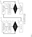
- a reduced capacity limit G1 may be calculated based on a determined capacity parameter G, in which case the car is considered at or about FULL but not OVERLOADED.
- the car 103 is already at or about full but not over loaded status.
- someone at a landing presses the hall call in another floor and the car reaches to the floor and the elevator door opens.
- a determination is made as to whether no one enters (or whether at least one passenger stays on the landing).
- the controller goes back to block 300. If the determination is "yes” because passengers enter (or at least one passenger stays behind), then the capacity parameter for the elevator car 103 at that time (e.g., G) is obtained at block 330.
- the elevator car 103 outputs a full signal at block 340 and ignores hall calls.
- the car 103 runs to the next car call destination per block 350.
- the capacity parameter is less than the reduced capacity limit is (G1) is, for example, less than 0.9 (or another reduction multiple) of G.
- the elevator remains full per block 340 and will only run to car calls, e.g., not hall calls per block 350. If the determination at block 360 is 'yes'', then per block 370 the operation status returns to normal operation, e.g., the car is not overloaded, even if at or near full.
- the controller 115 may be configured to determine that the reduced capacity limit is function (e.g., less than or equal to ninety percent, or other reduction multiple) of a previously programmed or determined reduced capacity limit instead of being a function of the then-measured capacity parameter.
- the capacity parameter represents information about the conditions of the elevator utilization that enable the controller to determine a modified or reduced capacity limit.
- the capacity parameter may also include time of day, season, geographic location, occupancy type and building utilization.
- the occupancy type may be one or more of cargo, passenger and robot, which may be a cleaning bot or other robot. That is, the embodiments may consider more than merely the available space by weight or volume.
- the system is able to more robustly identify when passengers in certain cohorts or passengers subject to certain environmental conditions may statistically feel the elevator car is too crowded to enter.
- Such embodiments may be configured to learn the practical limits which, even for the same-sized cab, varies geographically and by usage of the building (e.g.
- the controller 115 may reduce the capacity limit by a predetermined reduction multiple without first going through the process shown in FIG. 3 .
- the process shown in FIG. 3 may be utilized to fine-tune the reduced capacity limit that has been otherwise modified (reduced) based on time of day, season, geographic location, occupancy type and building utilization.
- the first sensor 220 may be onboard the elevator car 103 and may be configured to communicate with the controller 115 directly, e.g., via the wired or wireless network connection 235 as indicated below, or via the cloud service 240.
- the first sensor data may be processed in whole or part at one or more of the first sensor 220, the cloud service 240 and the controller 115. Processed portions may be stitched together at the controller 115 for form compiled data.
- one or more of passenger count, volume of available space or volume of occupied space may be derived from processing the first sensor data.
- the second sensor 225 may be onboard the elevator car 103 or located at the landing 125.
- the second sensor 225 may communicate with the controller 115, directly or via the cloud service 240.
- the second sensor data may be processed in whole or part at one or more of the second sensor, the cloud service 240 and the controller 115. Processed portions may be stitched together at the controller 115 for form compiled data.
- the second sensor 225 may be a motion sensor or depth sensor located onboard the elevator car 103, such as in the elevator doors 230, or on the landing.
- the second sensor 225 may also be camera, depth sensor or floor pressure sensor, located at the landing 125.
- the second sensor 225 may be a light curtain in the elevator door and/or hall door, etc., for example elevator doors 230 in FIG. 2 .
- the depth sensor may be configured to detect shapes of people, which the controller 115 identifies as people waiting at the landing.
- the above embodiments provide for the system to self-learn the effective load limit.
- the system detects cases when at least one passenger does not board the car, utilizing for example volume sensors both in the car and the hall so the system can sense if some passengers were left behind in the hall.
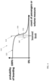
- the system can build a probability curve 300 shown in FIG. 4 , which graphs the probably of passengers entering the elevator car (Y axis) based on, for example, the current passenger count or measured volume (used or available) (X axis) in the elevator car.
- the system goal is to learn approximately where the curve takes a sharp downward, e.g., the learned limit (vertical line 320), which is the reduced capacity limit, which may represent a 90% boarding probability.
- the learned limit vertical line 320
- the reduced capacity limit which may represent a 90% boarding probability.
- the system may adjust the curve rightwards to an upper capacity tolerance or upper limit 330 to increase the reduced capacity limit.
- the system may adjust the curve leftwards by substantially the same amount as adjusted rightwards to a lower capacity tolerance or lower limit 340 to decrease the reduced capacity limit.
- the amount of adjusting to the left or right of the learned limit 320 may define an adjustment range or tolerance range 350 that may itself be learned and modified over time so that minimal overall adjustments are required to obtain the 90% (or thereabout) boarding probability. If the differential size of the tolerance range 350, between the reduced capacity limits 330/340, is too large, then the probability of a passenger boarding may drop to an unacceptable level, in which case the tolerance range 350 may be made smaller.
- the tolerance range 350 may be made larger and/or the learned limit 320 may shift to increase or decrease the reduced capacity limit.
- the size of the tolerance range 350 may initially be +/-1% of the boarding probability. Adjustments to the tolerance range 350 and movement of the learned limit 320 may be in increments of single percentages of the boarding probability, as one example. It should be appreciated that the boarding probability and tolerance range identified herein are only exemplary, and the true values for each could be higher or lower than those identified herein.
- the method includes identifying, at the controller 115 from first sensor data communicated via a first sensor 220, a capacity parameter of the elevator car 103.
- the capacity parameter may be: loaded weight; volume of available space; or volume of occupied space.
- the capacity parameter may further include one or more of time of day, season, geographic location, occupancy type and building utilization.
- the occupancy type may be one or more of cargo and passengers.
- the controller 115 may reduce the capacity limit by a predetermined reduction multiple without first going through the process shown in FIG. 3 .
- the process shown in FIG. 3 may be utilized to fine-tune the capacity limit that has been otherwise modified (reduced) based on time of day, season, geographic location, occupancy type and building utilization.
- the method includes determining, at the controller 115 from second sensor data communicated via a second sensor 225, that passengers remain outside the elevator car 103 when the elevator car 103 is stopped at a landing and its elevator doors 230 are open.
- the controller 115, the first sensor 220 and the second sensor 225 communicate with each other over a wireless network 235 of the type identified below.
- the method includes determining, at the controller 115 from the first sensor data and the second sensor data, a reduced capacity limit (e.g., relative to a design maximum capacity limit or previously determined reduce capacity limit) for the elevator car 103 as a function of the capacity parameter.
- the capacity parameter may be a measured weight when people are not entering the elevator and the capacity limit may be a predetermined reduction multiple of the capacity parameter.
- the method may include controlling the elevator car 103, by the controller 115, to disregard calls for service when the elevator car 103 is at or above the reduced capacity limit.
- the system may continue to run to hall calls as long as at least one person boards the elevator at a last hall call.
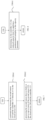
- block 510 may be further defined by block 510A1, which identifies that the method may include communicating, between the controller 115 and the first sensor 220, that may be onboard the elevator car 103, directly or via a cloud service 240.
- the method may include processing the first sensor data, in whole or in-part, at one or more of the first sensor 220, the cloud service 240 and the controller 115. Processed portions may be stitched together at the controller 115 for form compiled data.
- the method may include determining, from the first sensor data, one or more of passenger count, volume of available space and volume of occupied space.
- the second sensor 225 may be onboard the elevator car 103 or located at the landing 125.
- block 520 may be further defined by block 520A1, which identifies that the method may include communicating between the second sensor 225 and the controller 115 directly or via the cloud service 240.
- the method may include processing the second sensor data in whole or part at one or more of the second sensor 225, the cloud service 240 and the controller 115. Processed portions may be stitched together at the controller 115 for form compiled data.
- the second sensor 225 may be a motion sensor or depth sensor located onboard the elevator car 103, or on the landing 225.
- block 530 may be further defined by block 530A1, which identifies that the method may include determining, by the controller 115, the reduced capacity limit by applying a predetermined multiplier to the capacity parameter.
- the method may include determining, by the controller 115, that the reduced capacity limit may be less than or equal to ninety percent (or other reduction multiple) of a previously programed or determined capacity limit.
- FIG. 9 shows another embodiment for defining or expanding upon block 530 based on the discussion related to FIG. 4 , above.
- the method includes the controller 115 accumulating data related to passengers entering the elevator 103 in response to hall calls while the elevator car 103 is near its design capacity limit or previously determined reduced capacity limit (or other selected capacity limit).
- the method includes the controller 115 setting a reduced capacity limit that correlates to a 90% (or other percentage) boarding probability that a passenger will enter the car 103.
- the method includes the controller 115 setting a tolerance range around the reduced capacity limit. The tolerance range may be +/-1 % (or other percentage) of the boarding probability.
- the method may include the controller determining, at each hall call to which it responds, whether passengers enter the elevator car 103.
- the method may include the controller 115 increasing the reduced capacity limit by half the tolerance range to an upper capacity tolerance. Otherwise (no at 530B3) as shown in block 530B5 the method may include the controller 115 decreasing the reduced capacity limit by half the tolerance range to a lower capacity tolerance.
- the method includes determining whether the boarding probability is within acceptable limits over time, such as hours or days (as non-limiting examples). If so (yes at 530B6) then the controller 115 may return to block 540. Otherwise (no at 530B6) the controller 115, at block 530B7, may modify one or both of the tolerance range (making it larger or smaller) and the reduced capacity limit (increasing or decreasing the limit).
- the system 101 may utilize an actual available capacity in the elevator car 103 to determine a reduced capacity limit based on a number of passengers, cargo including luggage, time of day, season, geographic location, elevator use, etc. This reduced capacity limit should avoid a condition in which passengers avoid entering the elevator at a landing because it is perceived to be overcrowded.
- the system 101 may utilize various types of information to learn the reduced capacity limit, which, even for a same-sized elevator car 103 located elsewhere, varies culturally, geographically and by usage of the building. For example, passengers in one geographic location, such as a crowded city or densely populated university, may accept a more densely packed elevator car, while those in more rural areas or hospitals may expect a less packed elevator car.
- the system 101 may utilize sensors to detect when passengers in the hallway (or landing) decide not to board the elevator car 103. When passengers do not enter, a practical upper limit to the capacity may be determined, which may be less than a predetermined or preprogrammed capacity limit.
- a reduced capacity (e.g., a practical capacity) limit may also be determined by detecting and accounting for occupant types that are given a wider berth, e.g., a robot, an impaired person or a person with supportive machinery. For example, certain cohorts of passenger may be more or less comfortable about riding in elevators with robots as cleaning implements or otherwise. Capacity limits may be based on a time of day, e.g., people may be more willing to squeeze into an elevator during rush hour in an office building. As a further practical example, during a winter rush hour, a capacity limit based on load may be different than a summer rush hour due to the size of bulky clothing. Thus, over-crowding may occur with less loaded weight.
- the system may learn to reduce the overloading-weight when, for example, the car reaches a floor call and nobody gets on even though the elevator loading is below a predetermined capacity limit.
- the system may then adjust the capacity limit to, for example, a fractional percentage (such as ninety percent) of the reduced capacity limit, going forward under the same conditions, including time of day, season, geographic location, and type of elevator utilization, such as an office building.
- the elevator car 103 may thereafter purposely not respond to a floor call when the same conditions are met and the capacity is at or above the reduced capacity limit. Rather in such situations the system may transmit for the elevator car a "FULL" or "NON-STOP" signal to the controller 115, even though the actual weight in the elevator is less than the design capacity limit for loading.
- the system 101 may learn an effective full load limit that may be specific for a given building and may be adapted for variations in the amount of space taken by each call.
- the above embodiments may improve dispatching performance by maximizing utilization without assigning passengers to an elevator car 103 that may be deemed by the passengers to be too full.
- Sensor data identified herein may be obtained and processed separately, or simultaneously and stitched together, or a combination thereof, and may be processed in a raw or compiled form.
- the sensor data may be processed on the sensor (e.g. via edge computing), by controllers identified or implicated herein, on a cloud service, or by a combination of one or more of these computing systems.
- the sensor may communicate the data via wired or wireless transmission lines, applying one or more protocols as indicated below.
- Wireless connections may apply protocols that include local area network (LAN, or WLAN for wireless LAN) protocols.
- LAN protocols include WiFi technology, based on the Section 802.11 standards from the Institute of Electrical and Electronics Engineers (IEEE).
- Other applicable protocols include Low Power WAN (LPWAN), which is a wireless wide area network (WAN) designed to allow long-range communications at a low bit rates, to enable end devices to operate for extended periods of time (years) using battery power.
- LPWAN Low Power WAN
- WAN wireless wide area network
- Long Range WAN is one type of LPWAN maintained by the LoRa Alliance and is a media access control (MAC) layer protocol for transferring management and application messages between a network server and application server, respectively.
- MAC media access control
- LAN and WAN protocols may be generally considered TCP/IP protocols (transmission control protocol/Internet protocol), used to govern the connection of computer systems to the Internet.
- Wireless connections may also apply protocols that include private area network (PAN) protocols.
- PAN protocols include, for example, Bluetooth Low Energy (BTLE), which is a wireless technology standard designed and marketed by the Bluetooth Special Interest Group (SIG) for exchanging data over short distances using short-wavelength radio waves.
- BTLE Bluetooth Low Energy
- SIG Bluetooth Special Interest Group
- PAN protocols also include Zigbee, a technology based on Section 802.15.4 protocols from the IEEE, representing a suite of high-level communication protocols used to create personal area networks with small, low-power digital radios for low-power low-bandwidth needs.
- Such protocols also include Z-Wave, which is a wireless communications protocol supported by the Z-Wave Alliance that uses a mesh network, applying low-energy radio waves to communicate between devices such as appliances, allowing for wireless control of the same.
- Wireless connections may also include radio-frequency identification (RFID) technology, used for communicating with an integrated chip (IC), e.g., on an RFID smartcard.
- RFID radio-frequency identification
- Sub-1Ghz RF equipment operates in the ISM (industrial, scientific and medical) spectrum bands below Sub 1Ghz - typically in the 769 - 935 MHz, 315 Mhz and the 468 Mhz frequency range. This spectrum band below 1Ghz is particularly useful for RF IOT (internet of things) applications.
- IoT Internet of things
- the Internet of things (IoT) describes the network of physical objects-"things"-that are embedded with sensors, software, and other technologies for the purpose of connecting and exchanging data with other devices and systems over the Internet.
- LPWAN-IOT technologies include narrowband internet of things (NB-IOT) and Category M1 internet of things (Cat M1-IOT).
- Wireless communications for the disclosed systems may include cellular, e.g. 2G/3G/4G (etc.).
- Other wireless platforms based on RFID technologies include Near-Field-Communication (NFC), which is a set of communication protocols for low-speed communications, e.g., to exchange date between electronic devices over a short distance.
- NFC Near-Field-Communication
- NFC standards are defined by the ISO/IEC (defined below), the NFC Forum and the GSMA (Global System for Mobile Communications) group. The above is not intended on limiting the scope of applicable wireless technologies.
- Wired connections may include connections (cables/interfaces) under RS (recommended standard)-422, also known as the TIA/EIA-422, which is a technical standard supported by the Telecommunications Industry Association (TIA) and which originated by the Electronic Industries Alliance (EIA) that specifies electrical characteristics of a digital signaling circuit.
- Wired connections may also include (cables/interfaces) under the RS-232 standard for serial communication transmission of data, which formally defines signals connecting between a DTE (data terminal equipment) such as a computer terminal, and a DCE (data circuit-terminating equipment or data communication equipment), such as a modem.
- Wired connections may also include connections (cables/interfaces) under the Modbus serial communications protocol, managed by the Modbus Organization.
- Modbus is a master/slave protocol designed for use with its programmable logic controllers (PLCs) and which is a commonly available means of connecting industrial electronic devices. Wireless connections may also include connectors (cables/interfaces) under the PROFibus (Process Field Bus) standard managed by PROFIBUS & PROFINET International (PI). PROFibus which is a standard for fieldbus communication in automation technology, openly published as part of IEC (International Electrotechnical Commission) 61158. Wired communications may also be over a Controller Area Network (CAN) bus.
- a CAN is a vehicle bus standard that allow microcontrollers and devices to communicate with each other in applications without a host computer.
- CAN is a message-based protocol released by the International Organization for Standards (ISO). The above is not intended on limiting the scope of applicable wired technologies.
- the data When data is transmitted over a network between end processors as identified herein, the data may be transmitted in raw form or may be processed in whole or part at any one of the end processors or an intermediate processor, e.g., at a cloud service (e.g. where at least a portion of the transmission path is wireless) or other processor.
- the data may be parsed at any one of the processors, partially or completely processed or compiled, and may then be stitched together or maintained as separate packets of information.
- Each processor or controller identified herein may be, but is not limited to, a single-processor or multi-processor system of any of a wide array of possible architectures, including field programmable gate array (FPGA), central processing unit (CPU), application specific integrated circuits (ASIC), digital signal processor (DSP) or graphics processing unit (GPU) hardware arranged homogenously or heterogeneously.
- the memory identified herein may be but is not limited to a random access memory (RAM), read only memory (ROM), or other electronic, optical, magnetic or any other computer readable medium.
- the controller may further include, in addition to a processor and nonvolatile memory, one or more input and/or output (I/O) device interface(s) that are communicatively coupled via an onboard (local) interface to communicate among other devices.
- the onboard interface may include, for example but not limited to, an onboard system bus, including a control bus (for inter-device communications), an address bus (for physical addressing) and a data bus (for transferring data). That is, the system bus may enable the electronic communications between the processor, memory and I/O connections.
- the I/O connections may also include wired connections and/or wireless connections identified herein.
- the onboard interface may have additional elements, which are omitted for simplicity, such as controllers, buffers (caches), drivers, repeaters, and receivers to enable electronic communications.
- the memory may execute programs, access data, or lookup charts, or a combination of each, in furtherance of its processing, all of which may be stored in advance or received during execution of its processes by other computing devices, e.g., via a cloud service or other network connection identified herein with other processors.
- Embodiments can be in the form of processor-implemented processes and devices for practicing those processes, such as processor.
- Embodiments can also be in the form of computer code based modules, e.g., computer program code (e.g., computer program product) containing instructions embodied in tangible media (e.g., non-transitory computer readable medium), such as floppy diskettes, CD ROMs, hard drives, on processor registers as firmware, or any other non-transitory computer readable medium, wherein, when the computer program code is loaded into and executed by a computer, the computer becomes a device for practicing the embodiments.
- computer program code e.g., computer program product
- Embodiments can also be in the form of computer program code, for example, whether stored in a storage medium, loaded into and/or executed by a computer, or transmitted over some transmission medium, loaded into and/or executed by a computer, or transmitted over some transmission medium, such as over electrical wiring or cabling, through fiber optics, or via electromagnetic radiation, wherein, when the computer program code is loaded into and executed by a computer, the computer becomes an device for practicing the exemplary embodiments.
- the computer program code segments configure the microprocessor to create specific logic circuits.
Landscapes
- Engineering & Computer Science (AREA)
- Automation & Control Theory (AREA)
- Computer Networks & Wireless Communication (AREA)
- Mechanical Engineering (AREA)
- Elevator Control (AREA)
- Indicating And Signalling Devices For Elevators (AREA)
Claims (15)
- Aufzugssystem (101), umfassend:eine Steuerung (115);eine Aufzugskabine (103), die mit der Steuerung (115) wirkverbunden ist;einen ersten Sensor (220), der zum Bereitstellen erster Sensordaten an der Steuerung (115) konfiguriert ist, wobei die Steuerung (115) zum Identifizieren eines Kapazitätsparameters der Aufzugskabine (103) anhand der ersten Sensordaten konfiguriert ist, wobei der Kapazitätsparameter eines oder mehrere der Folgenden beinhaltet: Gewicht mit Last; Volumen des verfügbaren Raums; oder Volumen des belegten Raums;einen zweiten Sensor (225), der zum Bereitstellen zweiter Sensordaten an der Steuerung (115) konfiguriert ist, wobei die Steuerung (115) zum Bestimmen anhand der zweiten Sensordaten konfiguriert ist, dass Fahrgäste außerhalb der Aufzugskabine (103) verbleiben, wenn die Aufzugskabine (103) auf einem Stockwerk angehalten hat und ihre Aufzugstüren geöffnet sind; undwobei die Steuerung (115) zum Bestimmen einer reduzierte Kapazitätsgrenze für die Aufzugskabine (103) in Abhängigkeit von dem Kapazitätsparameter anhand der ersten Sensordaten und der zweiten Sensordaten konfiguriert ist;dadurch gekennzeichnet, dass die Steuerung (115) beim Bestimmen der reduzierten Kapazitätsgrenze zu Folgendem konfiguriert ist:Sammeln von Daten bezüglich Fahrgästen, die als Reaktion auf Etagenrufe in den Aufzug eintreten, während sich die Aufzugskabine (103) nahe ihrer Bemessungskapazitätsgrenze oder einer zuvor bestimmten reduzierten Kapazitätsgrenze befindet;Festlegen der reduzierten Kapazitätsgrenze, sodass sie mit einer vorbestimmten Betretungswahrscheinlichkeit korreliert, und Festlegen eines Toleranzbereichs um die reduzierte Kapazitätsgrenze;Bestimmen, ob die Betretungswahrscheinlichkeit im Zeitverlauf innerhalb akzeptabler Grenzen liegt; undnach Bestimmen, dass die Betretungswahrscheinlichkeit im Zeitverlauf außerhalb akzeptabler Grenzen liegt, Modifizieren eines oder beides von dem Toleranzbereich und der reduzierten Kapazitätsgrenze.
- System nach Anspruch 1, wobei die Steuerung (115), der erste Sensor (220) und der zweite Sensor (225) zum Kommunizieren über ein drahtloses Netzwerk (235) miteinander konfiguriert sind.
- System nach Anspruch 1 oder 2, wobei:
die Steuerung (115) zum Bestimmen der reduzierten Kapazitätsgrenze durch Anwenden eines vorbestimmten Multiplikators auf den Kapazitätsparameter konfiguriert ist. - System nach einem der vorhergehenden Ansprüche, wobei:der Kapazitätsparameter ferner einen oder mehrere von Tageszeit, Jahreszeit, geografischem Standort, Belegungsart und Gebäudenutzung beinhaltet; undwobei die Belegungsart eines oder mehrere von Fracht, Fahrgast oder Roboter ist.
- System nach einem der vorhergehenden Ansprüche, wobei:
die Steuerung (115) zum Steuern der Aufzugskabine (103) derart konfiguriert ist, dass Serviceanrufe ignoriert werden, wenn die Aufzugskabine (103) die reduzierte Kapazitätsgrenze erreicht hat oder überschreitet. - System nach einem der vorhergehenden Ansprüche, wobei:sich der erste Sensor (220) an Bord der Aufzugskabine (103) befindet und zum direkten Kommunizieren oder Kommunizieren über einen Cloud-Dienst (240) mit der Steuerung (115) konfiguriert ist unddie ersten Sensordaten ganz oder teilweise an einem oder mehreren von dem ersten Sensor (220), dem Cloud-Dienst (240) und der Steuerung (115) verarbeitet werden.
- System nach einem der vorhergehenden Ansprüche, wobei:
eines oder mehrere von Fahrgastanzahl, dem Volumen des verfügbaren Raums und dem Volumen des belegten Raums aus dem Verarbeiten der ersten Sensordaten abgeleitet werden. - System nach einem der vorhergehenden Ansprüche, wobei:der zweite Sensor (225) an Bord der Aufzugskabine (103) ist oder sich auf dem Stockwerk (125) befindet; undder zweite Sensor (225) mit der Steuerung (115) direkt oder über einen Cloud-Dienst (240) kommuniziert unddie zweiten Sensordaten ganz oder teilweise an einem oder mehreren von dem zweiten Sensor (225), dem Cloud-Dienst (240) und der Steuerung (115) verarbeitet werden.
- System nach einem der vorhergehenden Ansprüche, wobei:
der zweite Sensor (225) ein Bewegungssensor oder Tiefensensor ist, der sich auf dem Stockwerk (125) befindet. - System nach einem der vorhergehenden Ansprüche, wobei:
die Steuerung (115) beim Bestimmen der reduzierten Kapazitätsgrenze zu Folgendem konfiguriert ist:Bestimmen, ob Fahrgäste als Reaktion auf Etagenrufe in den Aufzug (103) eintreten; undnach Bestimmen, dass Fahrgäste als Reaktion auf Etagenrufe in den Aufzug eintreten, Erhöhen der reduzierten Kapazitätsgrenze um die Hälfte des Toleranzbereichs auf eine obere Kapazitätstoleranz, andernfalls Verringern der reduzierten Kapazitätsgrenze um die Hälfte des Toleranzbereichs auf eine untere Kapazitätstoleranz. - Verfahren zum Steuern einer Aufzugskabine (103) eines Aufzugssystems (101) mit einer Steuerung (115), die mit der Aufzugskabine (103) wirkverbunden ist, wobei das Verfahren Folgendes umfasst:
Identifizieren eines Kapazitätsparameters der Aufzugskabine (103) an der Steuerung (115) anhand erster über einen ersten Sensor (220) kommunizierter Sensordaten, wobei der Kapazitätsparameter mindestens eines von Folgenden beinhaltet:Gewicht mit Last; Volumen des verfügbaren Raums; oder Volumen des belegten Raums;Bestimmen an der Steuerung (115) anhand zweiter über einen zweiten Sensor (225) kommunizierter Sensordaten, dass Fahrgäste außerhalb der Aufzugskabine (103) verbleiben, wenn die Aufzugskabine (103) auf einem Stockwerk angehalten hat und ihre Aufzugstüren geöffnet sind; undBestimmen einer reduzierte Kapazitätsgrenze für die Aufzugskabine (103) in Abhängigkeit von dem Kapazitätsparameter an der Steuerung (115) anhand der ersten Sensordaten und der zweiten Sensordaten, wobei das Verfahren beim Bestimmen der reduzierten Kapazitätsgrenze Folgendes an der Steuerung beinhaltet:Sammeln von Daten bezüglich Fahrgästen, die als Reaktion auf Etagenrufe in den Aufzug eintreten, während sich die Aufzugskabine (103) nahe ihrer Bemessungskapazitätsgrenze oder einer zuvor bestimmten reduzierten Kapazitätsgrenze befindet;Festlegen der reduzierten Kapazitätsgrenze, sodass sie mit einer vorbestimmten Betretungswahrscheinlichkeit korreliert, und Festlegen eines Toleranzbereichs um die reduzierte Kapazitätsgrenze;Bestimmen, ob die Betretungswahrscheinlichkeit im Zeitverlauf innerhalb akzeptabler Grenzen liegt; undnach Bestimmen, dass die Betretungswahrscheinlichkeit im Zeitverlauf außerhalb akzeptabler Grenzen liegt, Modifizieren eines oder beides von dem Toleranzbereich und der reduzierten Kapazitätsgrenze. - Verfahren nach Anspruch 11, wobei:die Steuerung (115), der erste Sensor (220) und der zweite Sensor (225) miteinander über ein drahtloses Netzwerk (235) kommunizieren; und/oderwobei das Bestimmen der reduzierten Kapazitätsgrenze Anwenden eines vorbestimmten Multiplikators auf den Kapazitätsparameter beinhaltet.
- Verfahren nach Anspruch 11 oder 12, wobei:der Kapazitätsparameter ferner einen oder mehrere von Tageszeit, Jahreszeit, geografischem Standort, Belegungsart und Gebäudenutzung beinhaltet; unddie Belegungsart eines oder mehrere von Fracht, Fahrgast und Roboter ist.
- Verfahren nach Anspruch 11 bis 13, ferner umfassend:Steuern der Aufzugskabine (103) durch die Steuerung (115) derart, dass Serviceanrufe ignoriert werden, wenn die Aufzugskabine (103) die reduzierte Kapazitätsgrenze erreicht hat oder überschreitet; und/oderBestimmen eines oder mehrere von Fahrgastanzahl, dem Volumen des verfügbaren Raums und dem Volumen des belegten Raums anhand der ersten Sensordaten.
- Verfahren nach einem der Ansprüche 11 bis 14, wobei:sich der erste Sensor (220) an Bord der Aufzugskabine (103) befindet;wobei das Verfahren Folgendes umfasst:Kommunizieren zwischen der Steuerung (115) und dem ersten Sensor (220) direkt oder über einen Cloud-Dienst (240) undVerarbeiten der ersten Sensordaten ganz oder teilweise an einem oder mehreren von dem ersten Sensor (220), dem Cloud-Dienst (240) und der Steuerung (115); und/oderwobei der zweite Sensor (225) an Bord der Aufzugskabine (103) ist oder sich auf dem Stockwerk (125) befindet; unddas Verfahren ferner Folgendes umfasst:Kommunizieren zwischen dem zweiten Sensor (225) und der Steuerung (115) direkt oder über einen Cloud-Dienst (240) undVerarbeiten der zweiten Sensordaten ganz oder teilweise an einem oder mehreren von dem zweiten Sensor (225), dem Cloud-Dienst (240) und der Steuerung (115); und/oderwobei der zweite Sensor (225) einen Bewegungssensor oder Tiefensensor beinhaltet, der sich auf dem Stockwerk (125) befindet; und/oderwobei das Verfahren beim Bestimmen der reduzierten Kapazitätsgrenze Folgendes an der Steuerung beinhaltet:Bestimmen, ob Fahrgäste als Reaktion auf Etagenrufe in den Aufzug (103) eintreten; undnach Bestimmen, dass Fahrgäste als Reaktion auf Etagenrufe in den Aufzug eintreten, Erhöhen der reduzierten Kapazitätsgrenze um die Hälfte des Toleranzbereichs auf eine obere Kapazitätstoleranz, andernfalls Verringern der reduzierten Kapazitätsgrenze um die Hälfte des Toleranzbereichs auf eine untere Kapazitätstoleranz.
Applications Claiming Priority (1)
| Application Number | Priority Date | Filing Date | Title |
|---|---|---|---|
| CN202110418506.4A CN115215172A (zh) | 2021-04-19 | 2021-04-19 | 用于动态地修改电梯轿厢的容量限制的系统和方法 |
Publications (2)
| Publication Number | Publication Date |
|---|---|
| EP4079671A1 EP4079671A1 (de) | 2022-10-26 |
| EP4079671B1 true EP4079671B1 (de) | 2025-02-26 |
Family
ID=78829681
Family Applications (1)
| Application Number | Title | Priority Date | Filing Date |
|---|---|---|---|
| EP21213829.1A Active EP4079671B1 (de) | 2021-04-19 | 2021-12-10 | System und verfahren zur dynamischen änderung einer kapazitätsgrenze einer aufzugskabine |
Country Status (3)
| Country | Link |
|---|---|
| US (1) | US20220332540A1 (de) |
| EP (1) | EP4079671B1 (de) |
| CN (1) | CN115215172A (de) |
Families Citing this family (3)
| Publication number | Priority date | Publication date | Assignee | Title |
|---|---|---|---|---|
| DE102023109190A1 (de) * | 2023-04-12 | 2024-05-16 | Tk Elevator Innovation And Operations Gmbh | Verfahren zum Generieren von wartezeitschwellwertabhängigen Haltevorgaben sowie entsprechende Aufzuganlage und Verwendung |
| CN116639563A (zh) * | 2023-05-05 | 2023-08-25 | 北京声智科技有限公司 | 电梯控制方法、装置、电子设备及存储介质 |
| EP4488211A1 (de) * | 2023-07-03 | 2025-01-08 | KONE Corporation | Verfahren zur erkennung eines überlastzustands, überlastüberwachungssystem und aufzug |
Family Cites Families (16)
| Publication number | Priority date | Publication date | Assignee | Title |
|---|---|---|---|---|
| US7014015B2 (en) * | 2003-06-24 | 2006-03-21 | Mitsubishi Electric Research Laboratories, Inc. | Method and system for scheduling cars in elevator systems considering existing and future passengers |
| JP4931068B2 (ja) * | 2007-05-22 | 2012-05-16 | 東芝エレベータ株式会社 | エレベータの制御装置 |
| JP2012096901A (ja) * | 2010-11-02 | 2012-05-24 | Hitachi Ltd | エレベータ装置 |
| DE102014001971A1 (de) * | 2014-02-16 | 2015-08-20 | Martin Thimm | Aufzugssteuerung |
| US11099533B2 (en) * | 2014-05-07 | 2021-08-24 | Vivint, Inc. | Controlling a building system based on real time events |
| CN106995168B (zh) * | 2016-01-22 | 2019-04-05 | 三菱电机株式会社 | 电梯系统 |
| EP3281904B1 (de) * | 2016-08-09 | 2020-03-25 | Otis Elevator Company | Steuerungssysteme und -verfahren für aufzüge |
| US20180093859A1 (en) * | 2016-09-30 | 2018-04-05 | Otis Elevator Company | Occupant evacuation operation by allocating a variable number of cars to floors within an evacuation zone |
| US11999588B2 (en) * | 2018-07-25 | 2024-06-04 | Otis Elevator Company | Dynamic car assignment process |
| JP6815568B2 (ja) * | 2018-08-06 | 2021-01-20 | 三菱電機株式会社 | 運行管理装置および運行管理プログラム |
| US12043515B2 (en) * | 2018-08-16 | 2024-07-23 | Otis Elevator Company | Elevator system management utilizing machine learning |
| JP6889870B2 (ja) * | 2019-05-30 | 2021-06-18 | フジテック株式会社 | エレベータの制御システム |
| US20210221648A1 (en) * | 2020-01-20 | 2021-07-22 | Pixart Imaging Inc. | Anti-pinch device, space computing device and hovering control device |
| EP4139238B1 (de) * | 2020-04-24 | 2025-06-04 | KONE Corporation | Verfahren zum betreiben einer aufzugsanlage und aufzugsanlage |
| US20230391583A1 (en) * | 2020-11-04 | 2023-12-07 | Hitachi, Ltd. | Elevator and Control Method for the Same |
| US20220185625A1 (en) * | 2020-12-15 | 2022-06-16 | Abacus Sensor, Inc. | Camera-based sensing devices for performing offline machine learning inference and computer vision |
-
2021
- 2021-04-19 CN CN202110418506.4A patent/CN115215172A/zh active Pending
- 2021-11-30 US US17/537,754 patent/US20220332540A1/en active Pending
- 2021-12-10 EP EP21213829.1A patent/EP4079671B1/de active Active
Also Published As
| Publication number | Publication date |
|---|---|
| US20220332540A1 (en) | 2022-10-20 |
| EP4079671A1 (de) | 2022-10-26 |
| CN115215172A (zh) | 2022-10-21 |
Similar Documents
| Publication | Publication Date | Title |
|---|---|---|
| EP4079671B1 (de) | System und verfahren zur dynamischen änderung einer kapazitätsgrenze einer aufzugskabine | |
| EP3609205B1 (de) | Drahtlosdatenkommunikation in einem system | |
| EP3643663A1 (de) | System und verfahren zur automatischen bereitstellung eines aufzugsdienstes in einem gebäude an einen fahrgast, wenn der fahrgast ein zimmer im gebäude verlässt | |
| CN116238977B (zh) | 被配置用于对其外部表面执行自评估的机器人 | |
| US12540053B2 (en) | Elevator system with cabin divider | |
| EP4635887A1 (de) | System und verfahren zum betrieb eines aufzugssystems zur auswahl einer aufzugskabine aus einer aufzugskabine | |
| EP3915919B1 (de) | Aufzugsverwaltungssystem, das kombinierte betriebs- und positionsdaten an eine aufzugsverwaltungszentrale überträgt | |
| EP4019449A1 (de) | System und verfahren zur behebung von antriebsfehlern in einem personenbeförderungssystem | |
| EP4527774A1 (de) | System und verfahren zur bereitstellung von pit-zugangsschutz | |
| EP3666711B1 (de) | System und verfahren zum betrieb eines aufzugsystems während einer abriegelung | |
| US20250115461A1 (en) | System and method for determining a travel intent of an elevator passenger and providing responsive alerts | |
| EP4382468A1 (de) | Aufzugssystem mit konfiguration zur durchführung einer selbstdiagnose und verfahren zum betrieb des aufzugssystems | |
| US20260008651A1 (en) | System and method for updating code in passenger conveyance systems | |
| US20260001742A1 (en) | Passenger conveyor system that monitors status of controller operating system and pushes updates to same | |
| US12422252B2 (en) | Hoistway survey tool and method of surveying a hoistway | |
| EP4477605A1 (de) | Aufzugssystem mit konfiguration zur schätzung einer aufzugskabinengeschwindigkeit zur anpassung der virtuellen sicherheitsnetzaktionen am kabinenoberteil | |
| US20240409369A1 (en) | Top of car handrail virtual safety net | |
| EP4582365A1 (de) | Aufzugssystem mit konfiguration zur bereitstellung eines kabinentons auf basis von benutzerfeedback | |
| EP3929128A1 (de) | Sensorausrichtungsanzeige für zustandsbasierte wartungserfassung |
Legal Events
| Date | Code | Title | Description |
|---|---|---|---|
| PUAI | Public reference made under article 153(3) epc to a published international application that has entered the european phase |
Free format text: ORIGINAL CODE: 0009012 |
|
| STAA | Information on the status of an ep patent application or granted ep patent |
Free format text: STATUS: THE APPLICATION HAS BEEN PUBLISHED |
|
| AK | Designated contracting states |
Kind code of ref document: A1 Designated state(s): AL AT BE BG CH CY CZ DE DK EE ES FI FR GB GR HR HU IE IS IT LI LT LU LV MC MK MT NL NO PL PT RO RS SE SI SK SM TR |
|
| STAA | Information on the status of an ep patent application or granted ep patent |
Free format text: STATUS: REQUEST FOR EXAMINATION WAS MADE |
|
| 17P | Request for examination filed |
Effective date: 20230426 |
|
| RBV | Designated contracting states (corrected) |
Designated state(s): AL AT BE BG CH CY CZ DE DK EE ES FI FR GB GR HR HU IE IS IT LI LT LU LV MC MK MT NL NO PL PT RO RS SE SI SK SM TR |
|
| STAA | Information on the status of an ep patent application or granted ep patent |
Free format text: STATUS: EXAMINATION IS IN PROGRESS |
|
| 17Q | First examination report despatched |
Effective date: 20240212 |
|
| GRAP | Despatch of communication of intention to grant a patent |
Free format text: ORIGINAL CODE: EPIDOSNIGR1 |
|
| STAA | Information on the status of an ep patent application or granted ep patent |
Free format text: STATUS: GRANT OF PATENT IS INTENDED |
|
| INTG | Intention to grant announced |
Effective date: 20241118 |
|
| GRAS | Grant fee paid |
Free format text: ORIGINAL CODE: EPIDOSNIGR3 |
|
| GRAA | (expected) grant |
Free format text: ORIGINAL CODE: 0009210 |
|
| STAA | Information on the status of an ep patent application or granted ep patent |
Free format text: STATUS: THE PATENT HAS BEEN GRANTED |
|
| AK | Designated contracting states |
Kind code of ref document: B1 Designated state(s): AL AT BE BG CH CY CZ DE DK EE ES FI FR GB GR HR HU IE IS IT LI LT LU LV MC MK MT NL NO PL PT RO RS SE SI SK SM TR |
|
| REG | Reference to a national code |
Ref country code: GB Ref legal event code: FG4D |
|
| REG | Reference to a national code |
Ref country code: CH Ref legal event code: EP |
|
| REG | Reference to a national code |
Ref country code: DE Ref legal event code: R096 Ref document number: 602021026718 Country of ref document: DE |
|
| REG | Reference to a national code |
Ref country code: IE Ref legal event code: FG4D |
|
| REG | Reference to a national code |
Ref country code: NL Ref legal event code: MP Effective date: 20250226 |
|
| PG25 | Lapsed in a contracting state [announced via postgrant information from national office to epo] |
Ref country code: RS Free format text: LAPSE BECAUSE OF FAILURE TO SUBMIT A TRANSLATION OF THE DESCRIPTION OR TO PAY THE FEE WITHIN THE PRESCRIBED TIME-LIMIT Effective date: 20250526 |
|
| PG25 | Lapsed in a contracting state [announced via postgrant information from national office to epo] |
Ref country code: FI Free format text: LAPSE BECAUSE OF FAILURE TO SUBMIT A TRANSLATION OF THE DESCRIPTION OR TO PAY THE FEE WITHIN THE PRESCRIBED TIME-LIMIT Effective date: 20250226 |
|
| PG25 | Lapsed in a contracting state [announced via postgrant information from national office to epo] |
Ref country code: PL Free format text: LAPSE BECAUSE OF FAILURE TO SUBMIT A TRANSLATION OF THE DESCRIPTION OR TO PAY THE FEE WITHIN THE PRESCRIBED TIME-LIMIT Effective date: 20250226 |
|
| PG25 | Lapsed in a contracting state [announced via postgrant information from national office to epo] |
Ref country code: ES Free format text: LAPSE BECAUSE OF FAILURE TO SUBMIT A TRANSLATION OF THE DESCRIPTION OR TO PAY THE FEE WITHIN THE PRESCRIBED TIME-LIMIT Effective date: 20250226 |
|
| REG | Reference to a national code |
Ref country code: LT Ref legal event code: MG9D |
|
| PG25 | Lapsed in a contracting state [announced via postgrant information from national office to epo] |
Ref country code: NO Free format text: LAPSE BECAUSE OF FAILURE TO SUBMIT A TRANSLATION OF THE DESCRIPTION OR TO PAY THE FEE WITHIN THE PRESCRIBED TIME-LIMIT Effective date: 20250526 Ref country code: IS Free format text: LAPSE BECAUSE OF FAILURE TO SUBMIT A TRANSLATION OF THE DESCRIPTION OR TO PAY THE FEE WITHIN THE PRESCRIBED TIME-LIMIT Effective date: 20250626 |
|
| PG25 | Lapsed in a contracting state [announced via postgrant information from national office to epo] |
Ref country code: NL Free format text: LAPSE BECAUSE OF FAILURE TO SUBMIT A TRANSLATION OF THE DESCRIPTION OR TO PAY THE FEE WITHIN THE PRESCRIBED TIME-LIMIT Effective date: 20250226 |
|
| PG25 | Lapsed in a contracting state [announced via postgrant information from national office to epo] |
Ref country code: HR Free format text: LAPSE BECAUSE OF FAILURE TO SUBMIT A TRANSLATION OF THE DESCRIPTION OR TO PAY THE FEE WITHIN THE PRESCRIBED TIME-LIMIT Effective date: 20250226 |
|
| PG25 | Lapsed in a contracting state [announced via postgrant information from national office to epo] |
Ref country code: LV Free format text: LAPSE BECAUSE OF FAILURE TO SUBMIT A TRANSLATION OF THE DESCRIPTION OR TO PAY THE FEE WITHIN THE PRESCRIBED TIME-LIMIT Effective date: 20250226 Ref country code: PT Free format text: LAPSE BECAUSE OF FAILURE TO SUBMIT A TRANSLATION OF THE DESCRIPTION OR TO PAY THE FEE WITHIN THE PRESCRIBED TIME-LIMIT Effective date: 20250626 |
|
| PG25 | Lapsed in a contracting state [announced via postgrant information from national office to epo] |
Ref country code: BG Free format text: LAPSE BECAUSE OF FAILURE TO SUBMIT A TRANSLATION OF THE DESCRIPTION OR TO PAY THE FEE WITHIN THE PRESCRIBED TIME-LIMIT Effective date: 20250226 Ref country code: GR Free format text: LAPSE BECAUSE OF FAILURE TO SUBMIT A TRANSLATION OF THE DESCRIPTION OR TO PAY THE FEE WITHIN THE PRESCRIBED TIME-LIMIT Effective date: 20250527 |
|
| REG | Reference to a national code |
Ref country code: AT Ref legal event code: MK05 Ref document number: 1770482 Country of ref document: AT Kind code of ref document: T Effective date: 20250226 |
|
| PG25 | Lapsed in a contracting state [announced via postgrant information from national office to epo] |
Ref country code: SE Free format text: LAPSE BECAUSE OF FAILURE TO SUBMIT A TRANSLATION OF THE DESCRIPTION OR TO PAY THE FEE WITHIN THE PRESCRIBED TIME-LIMIT Effective date: 20250226 |
|
| PG25 | Lapsed in a contracting state [announced via postgrant information from national office to epo] |
Ref country code: SM Free format text: LAPSE BECAUSE OF FAILURE TO SUBMIT A TRANSLATION OF THE DESCRIPTION OR TO PAY THE FEE WITHIN THE PRESCRIBED TIME-LIMIT Effective date: 20250226 |
|
| PG25 | Lapsed in a contracting state [announced via postgrant information from national office to epo] |
Ref country code: DK Free format text: LAPSE BECAUSE OF FAILURE TO SUBMIT A TRANSLATION OF THE DESCRIPTION OR TO PAY THE FEE WITHIN THE PRESCRIBED TIME-LIMIT Effective date: 20250226 |
|
| PG25 | Lapsed in a contracting state [announced via postgrant information from national office to epo] |
Ref country code: IT Free format text: LAPSE BECAUSE OF FAILURE TO SUBMIT A TRANSLATION OF THE DESCRIPTION OR TO PAY THE FEE WITHIN THE PRESCRIBED TIME-LIMIT Effective date: 20250226 |
|
| PG25 | Lapsed in a contracting state [announced via postgrant information from national office to epo] |
Ref country code: AT Free format text: LAPSE BECAUSE OF FAILURE TO SUBMIT A TRANSLATION OF THE DESCRIPTION OR TO PAY THE FEE WITHIN THE PRESCRIBED TIME-LIMIT Effective date: 20250226 |
|
| PG25 | Lapsed in a contracting state [announced via postgrant information from national office to epo] |
Ref country code: CZ Free format text: LAPSE BECAUSE OF FAILURE TO SUBMIT A TRANSLATION OF THE DESCRIPTION OR TO PAY THE FEE WITHIN THE PRESCRIBED TIME-LIMIT Effective date: 20250226 Ref country code: EE Free format text: LAPSE BECAUSE OF FAILURE TO SUBMIT A TRANSLATION OF THE DESCRIPTION OR TO PAY THE FEE WITHIN THE PRESCRIBED TIME-LIMIT Effective date: 20250226 |
|
| PG25 | Lapsed in a contracting state [announced via postgrant information from national office to epo] |
Ref country code: RO Free format text: LAPSE BECAUSE OF FAILURE TO SUBMIT A TRANSLATION OF THE DESCRIPTION OR TO PAY THE FEE WITHIN THE PRESCRIBED TIME-LIMIT Effective date: 20250226 |
|
| PG25 | Lapsed in a contracting state [announced via postgrant information from national office to epo] |
Ref country code: SK Free format text: LAPSE BECAUSE OF FAILURE TO SUBMIT A TRANSLATION OF THE DESCRIPTION OR TO PAY THE FEE WITHIN THE PRESCRIBED TIME-LIMIT Effective date: 20250226 |
|
| REG | Reference to a national code |
Ref country code: DE Ref legal event code: R097 Ref document number: 602021026718 Country of ref document: DE |
|
| PLBE | No opposition filed within time limit |
Free format text: ORIGINAL CODE: 0009261 |
|
| STAA | Information on the status of an ep patent application or granted ep patent |
Free format text: STATUS: NO OPPOSITION FILED WITHIN TIME LIMIT |
|
| PGFP | Annual fee paid to national office [announced via postgrant information from national office to epo] |
Ref country code: DE Payment date: 20251126 Year of fee payment: 5 |
|
| PGFP | Annual fee paid to national office [announced via postgrant information from national office to epo] |
Ref country code: FR Payment date: 20251120 Year of fee payment: 5 |
|
| 26N | No opposition filed |
Effective date: 20251127 |