EP4079658A1 - Passiervorrichtung, inhaltsempfangsmechanismus mit passiervorrichtung, medikamentenverwaltungsvorrichtung und verfahren zum bestimmen, ob der inhalt ausgegeben werden soll oder nicht - Google Patents
Passiervorrichtung, inhaltsempfangsmechanismus mit passiervorrichtung, medikamentenverwaltungsvorrichtung und verfahren zum bestimmen, ob der inhalt ausgegeben werden soll oder nicht Download PDFInfo
- Publication number
- EP4079658A1 EP4079658A1 EP20903392.7A EP20903392A EP4079658A1 EP 4079658 A1 EP4079658 A1 EP 4079658A1 EP 20903392 A EP20903392 A EP 20903392A EP 4079658 A1 EP4079658 A1 EP 4079658A1
- Authority
- EP
- European Patent Office
- Prior art keywords
- light
- content
- amount
- receiving unit
- light receiving
- Prior art date
- Legal status (The legal status is an assumption and is not a legal conclusion. Google has not performed a legal analysis and makes no representation as to the accuracy of the status listed.)
- Granted
Links
Images


Classifications
-
- B—PERFORMING OPERATIONS; TRANSPORTING
- B65—CONVEYING; PACKING; STORING; HANDLING THIN OR FILAMENTARY MATERIAL
- B65D—CONTAINERS FOR STORAGE OR TRANSPORT OF ARTICLES OR MATERIALS, e.g. BAGS, BARRELS, BOTTLES, BOXES, CANS, CARTONS, CRATES, DRUMS, JARS, TANKS, HOPPERS, FORWARDING CONTAINERS; ACCESSORIES, CLOSURES, OR FITTINGS THEREFOR; PACKAGING ELEMENTS; PACKAGES
- B65D83/00—Containers or packages with special means for dispensing contents
- B65D83/04—Containers or packages with special means for dispensing contents for dispensing annular, disc-shaped, spherical or like small articles, e.g. tablets or pills
- B65D83/0409—Containers or packages with special means for dispensing contents for dispensing annular, disc-shaped, spherical or like small articles, e.g. tablets or pills the dispensing means being adapted for delivering one article, or a single dose, upon each actuation
- B65D83/0427—Containers or packages with special means for dispensing contents for dispensing annular, disc-shaped, spherical or like small articles, e.g. tablets or pills the dispensing means being adapted for delivering one article, or a single dose, upon each actuation the articles being dispensed by inverting the container each time, by which action movable parts may be displaced by their own weight
-
- A—HUMAN NECESSITIES
- A61—MEDICAL OR VETERINARY SCIENCE; HYGIENE
- A61J—CONTAINERS SPECIALLY ADAPTED FOR MEDICAL OR PHARMACEUTICAL PURPOSES; DEVICES OR METHODS SPECIALLY ADAPTED FOR BRINGING PHARMACEUTICAL PRODUCTS INTO PARTICULAR PHYSICAL OR ADMINISTERING FORMS; DEVICES FOR ADMINISTERING FOOD OR MEDICINES ORALLY; BABY COMFORTERS; DEVICES FOR RECEIVING SPITTLE
- A61J7/00—Devices for administering medicines orally, e.g. spoons; Pill counting devices; Arrangements for time indication or reminder for taking medicine
- A61J7/0076—Medicament distribution means
-
- A—HUMAN NECESSITIES
- A61—MEDICAL OR VETERINARY SCIENCE; HYGIENE
- A61J—CONTAINERS SPECIALLY ADAPTED FOR MEDICAL OR PHARMACEUTICAL PURPOSES; DEVICES OR METHODS SPECIALLY ADAPTED FOR BRINGING PHARMACEUTICAL PRODUCTS INTO PARTICULAR PHYSICAL OR ADMINISTERING FORMS; DEVICES FOR ADMINISTERING FOOD OR MEDICINES ORALLY; BABY COMFORTERS; DEVICES FOR RECEIVING SPITTLE
- A61J1/00—Containers specially adapted for medical or pharmaceutical purposes
- A61J1/03—Containers specially adapted for medical or pharmaceutical purposes for pills or tablets
-
- A—HUMAN NECESSITIES
- A61—MEDICAL OR VETERINARY SCIENCE; HYGIENE
- A61J—CONTAINERS SPECIALLY ADAPTED FOR MEDICAL OR PHARMACEUTICAL PURPOSES; DEVICES OR METHODS SPECIALLY ADAPTED FOR BRINGING PHARMACEUTICAL PRODUCTS INTO PARTICULAR PHYSICAL OR ADMINISTERING FORMS; DEVICES FOR ADMINISTERING FOOD OR MEDICINES ORALLY; BABY COMFORTERS; DEVICES FOR RECEIVING SPITTLE
- A61J7/00—Devices for administering medicines orally, e.g. spoons; Pill counting devices; Arrangements for time indication or reminder for taking medicine
- A61J7/04—Arrangements for time indication or reminder for taking medicine, e.g. programmed dispensers
- A61J7/0409—Arrangements for time indication or reminder for taking medicine, e.g. programmed dispensers with timers
- A61J7/0427—Arrangements for time indication or reminder for taking medicine, e.g. programmed dispensers with timers with direct interaction with a dispensing or delivery system
-
- A—HUMAN NECESSITIES
- A61—MEDICAL OR VETERINARY SCIENCE; HYGIENE
- A61J—CONTAINERS SPECIALLY ADAPTED FOR MEDICAL OR PHARMACEUTICAL PURPOSES; DEVICES OR METHODS SPECIALLY ADAPTED FOR BRINGING PHARMACEUTICAL PRODUCTS INTO PARTICULAR PHYSICAL OR ADMINISTERING FORMS; DEVICES FOR ADMINISTERING FOOD OR MEDICINES ORALLY; BABY COMFORTERS; DEVICES FOR RECEIVING SPITTLE
- A61J7/00—Devices for administering medicines orally, e.g. spoons; Pill counting devices; Arrangements for time indication or reminder for taking medicine
- A61J7/04—Arrangements for time indication or reminder for taking medicine, e.g. programmed dispensers
- A61J7/0409—Arrangements for time indication or reminder for taking medicine, e.g. programmed dispensers with timers
- A61J7/0481—Arrangements for time indication or reminder for taking medicine, e.g. programmed dispensers with timers working on a schedule basis
-
- B—PERFORMING OPERATIONS; TRANSPORTING
- B65—CONVEYING; PACKING; STORING; HANDLING THIN OR FILAMENTARY MATERIAL
- B65D—CONTAINERS FOR STORAGE OR TRANSPORT OF ARTICLES OR MATERIALS, e.g. BAGS, BARRELS, BOTTLES, BOXES, CANS, CARTONS, CRATES, DRUMS, JARS, TANKS, HOPPERS, FORWARDING CONTAINERS; ACCESSORIES, CLOSURES, OR FITTINGS THEREFOR; PACKAGING ELEMENTS; PACKAGES
- B65D47/00—Closures with filling and discharging, or with discharging, devices
- B65D47/04—Closures with discharging devices other than pumps
- B65D47/20—Closures with discharging devices other than pumps comprising hand-operated members for controlling discharge
-
- B—PERFORMING OPERATIONS; TRANSPORTING
- B65—CONVEYING; PACKING; STORING; HANDLING THIN OR FILAMENTARY MATERIAL
- B65D—CONTAINERS FOR STORAGE OR TRANSPORT OF ARTICLES OR MATERIALS, e.g. BAGS, BARRELS, BOTTLES, BOXES, CANS, CARTONS, CRATES, DRUMS, JARS, TANKS, HOPPERS, FORWARDING CONTAINERS; ACCESSORIES, CLOSURES, OR FITTINGS THEREFOR; PACKAGING ELEMENTS; PACKAGES
- B65D83/00—Containers or packages with special means for dispensing contents
- B65D83/06—Containers or packages with special means for dispensing contents for dispensing powdered or granular material
-
- G—PHYSICS
- G01—MEASURING; TESTING
- G01J—MEASUREMENT OF INTENSITY, VELOCITY, SPECTRAL CONTENT, POLARISATION, PHASE OR PULSE CHARACTERISTICS OF INFRARED, VISIBLE OR ULTRAVIOLET LIGHT; COLORIMETRY; RADIATION PYROMETRY
- G01J1/00—Photometry, e.g. photographic exposure meter
- G01J1/02—Details
-
- G—PHYSICS
- G01—MEASURING; TESTING
- G01V—GEOPHYSICS; GRAVITATIONAL MEASUREMENTS; DETECTING MASSES OR OBJECTS; TAGS
- G01V8/00—Prospecting or detecting by optical means
- G01V8/10—Detecting, e.g. by using light barriers
- G01V8/12—Detecting, e.g. by using light barriers using one transmitter and one receiver
-
- A—HUMAN NECESSITIES
- A61—MEDICAL OR VETERINARY SCIENCE; HYGIENE
- A61J—CONTAINERS SPECIALLY ADAPTED FOR MEDICAL OR PHARMACEUTICAL PURPOSES; DEVICES OR METHODS SPECIALLY ADAPTED FOR BRINGING PHARMACEUTICAL PRODUCTS INTO PARTICULAR PHYSICAL OR ADMINISTERING FORMS; DEVICES FOR ADMINISTERING FOOD OR MEDICINES ORALLY; BABY COMFORTERS; DEVICES FOR RECEIVING SPITTLE
- A61J1/00—Containers specially adapted for medical or pharmaceutical purposes
- A61J1/14—Details; Accessories therefor
- A61J1/1412—Containers with closing means, e.g. caps
-
- A—HUMAN NECESSITIES
- A61—MEDICAL OR VETERINARY SCIENCE; HYGIENE
- A61J—CONTAINERS SPECIALLY ADAPTED FOR MEDICAL OR PHARMACEUTICAL PURPOSES; DEVICES OR METHODS SPECIALLY ADAPTED FOR BRINGING PHARMACEUTICAL PRODUCTS INTO PARTICULAR PHYSICAL OR ADMINISTERING FORMS; DEVICES FOR ADMINISTERING FOOD OR MEDICINES ORALLY; BABY COMFORTERS; DEVICES FOR RECEIVING SPITTLE
- A61J2200/00—General characteristics or adaptations
- A61J2200/70—Device provided with specific sensor or indicating means
-
- B—PERFORMING OPERATIONS; TRANSPORTING
- B65—CONVEYING; PACKING; STORING; HANDLING THIN OR FILAMENTARY MATERIAL
- B65D—CONTAINERS FOR STORAGE OR TRANSPORT OF ARTICLES OR MATERIALS, e.g. BAGS, BARRELS, BOTTLES, BOXES, CANS, CARTONS, CRATES, DRUMS, JARS, TANKS, HOPPERS, FORWARDING CONTAINERS; ACCESSORIES, CLOSURES, OR FITTINGS THEREFOR; PACKAGING ELEMENTS; PACKAGES
- B65D2547/00—Closures with filling and discharging, or with discharging, devices
- B65D2547/04—Closures with discharging devices other than pumps
- B65D2547/06—Closures with discharging devices other than pumps with pouring spouts ot tubes; with discharge nozzles or passages
- B65D2547/063—Details of spouts
Definitions
- the present invention relates to a content passing device, and more particularly, to a passing device and a receiving mechanism that enable a fixed amount of content to be discharged from the receiving mechanism and detect whether the content is discharged, a method of determining whether content is discharged, and a medication management device that manages a user to take a fixed amount of medications.
- health supplements such as vitamins and the like, medicines, and foods such as chocolate, candy, and the like, are sold as solid content in the form of capsules or tablets (pill) or as powdery content in the form of being stored in containers.
- Tools or small parts such as bolts, nuts, and the like, are also manufactured as solid content (hereinafter referred to as "content") and used or managed in a state of being accommodated in containers.
- General content accommodating containers have a structure including a container body in which a large amount of content is accommodated and a cover that is coupled to an inlet of the container body to be opened or closed. Therefore, in order to ingest or use the content, the cover is opened from the container body and then the accommodated content is withdrawn.
- a conventional accommodating container in order to acquire the content, when a user takes out the content by tilting the container body or putting his or her hand into the container body, the content pours out all at once or as much comes out as is being grasped by the hand. Therefore, it is difficult to simply take out the content one by one or by a required demand amount.
- the present invention has been devised to improve the above problems and is directed to providing a content passing device that accurately detects content discharged from a receiving mechanism for accommodating the content therein.
- the present invention is also directed to providing a content passing device and a receiving mechanism that enable a user to take a fixed amount of medications through the above object, and a medication management device.
- the present invention is also directed to providing a passing device that automatically detects discharge of content by accurately distinguishing a jammed state and discharge of the content, and a receiving mechanism.
- the present invention is also directed to providing a method of determining with high accuracy whether content is discharged from a receiving mechanism equipped with the passing device.
- One aspect of the present invention provides a passing device for being coupled to a container body that accommodates content, the passing device including a passing operation unit configured to guide a movement of content, a passing movement unit that is rotatably installed in the passing operation unit and is rotated so that the content passes therethrough, and a detection unit that is provided in the passing operation unit to detect the content discharged from the container body through the passing device.
- the content may be discharged from the container body through the passing operation unit by the rotation of the passing movement unit.
- the detection unit may include a light receiving unit and a light emitting unit, wherein light emitted from the light emitting unit may pass through a path through which the content is moved to be discharged and may be detected by the light receiving unit. Whether the content is discharged may be determined based on an amount of the light detected by the light receiving unit.
- whether the content is discharged may be determined based on a change pattern of the amount of the light detected by the light receiving unit over time.
- the passing operation unit may include a duct-shaped passage portion that forms a movement path for discharging a fixed amount of content.
- the passing operation unit may further include a guide portion that is connected to the passage portion to guide the content. The content may be moved along the guide portion, introduced into the passage portion, and then discharged to the outside through an opening at an upper end of the passage portion.
- the guide portion may form a part of the curved inner wall of the container body or may be made of a separate part.
- the passing movement unit may include an opening member that opens or closes the opening, a rotation shaft serving as a center of a rotational movement, and a blocking member that is connected to the rotation shaft and is rotated together with the opening member, wherein the passing movement unit may form one side wall of the passage portion.
- the opening member of the passing movement unit may form one side wall of the passage portion in a state in which the opening member blocks the opening.
- the content may move through the tilted passage portion from an upstream to a downstream and collide with the opening member to apply a force.
- the passing movement unit may be rotated about the rotation shaft so that the opening may be opened, and thus the content may be discharged to the outside.
- the light receiving unit and the light emitting unit may be disposed to face each other on both side walls of the passage portion formed on left and right sides of the one side wall.
- the light receiving unit may include a first light receiving unit disposed at an upstream side of the path through which the content is moved to be discharged, and a second light receiving unit disposed at a downstream side of the path, wherein the light emitting unit may include one or more light emitting units disposed to face the light receiving unit.
- Whether the content is discharged may be determined based on a change pattern in amount of the light over time, which is detected by each of the first light receiving unit and the second light receiving unit.
- a process of determining whether content is discharged may be executed by a sensor control unit included in the passing device, or the process of determining whether the content is discharged may be determined by an external device that directly or indirectly receives a signal from the light receiving unit through wireless communication.
- the sensor control unit may determine that the content has passed through the first light receiving unit region, and when the amount of the light detected by the second light receiving unit is changed from a second standard light amount range to a second reference light amount or less and then enters the second standard light amount range again, the sensor control unit may determine that the content has passed through the second light receiving unit region.
- the first standard light amount range and the second standard light amount range may be ranges of the amount of the light detected by the first light receiving unit and the second light receiving unit, respectively, in a state in which the content does not pass therethrough. When it is determined that the content has passed through the first light receiving unit region before the second light receiving unit region, it may be determined that the content is normally discharged.
- a first time point at which the amount of the light detected by the first light receiving unit is changed from a state of falling within a first standard light amount range to a first reference light amount or less and then enters the first standard light amount range again may be compared with a second time point at which the amount of the light detected by the second light receiving unit is changed from a state of falling within a second standard light amount range to a second reference light amount or less and then enters the second standard light amount range again, and when the first time point is the same as or earlier than the second time point, the sensor control unit or the processor of the external device may determines that the content is discharged.
- a first time point at which the amount of the light detected by the first light receiving unit reaches a downward peak and then reaches a first reference value may be compared with a second time point at which the amount of the light detected by the second light receiving unit reaches the downward peak and then reaches a second reference value, and when the first time point is the same as or earlier than the second time point, it may be determined that the content is discharged.
- a path through which content is moved to be discharged may be formed by a duct-shaped passage portion, and a light receiving unit disposed on one side of the passage portion may be composed of two photodiodes, wherein the two photodiodes may be arranged in a line along the movement path of the content of the passage portion.
- a light emitting unit that is disposed on another side of the passage portion to face the light receiving unit may emit light toward the passage portion, and the two photodiodes may receive the light emitted from the light emitting unit. Whether the content is discharged may be determined based on the amount of the light detected by the two photodiodes.
- a signal detected by the detection unit may be processed by an information processing device included in the passing device or may be processed by a separate external device.
- Another aspect of the present invention provides a medication management device, including the passing device, a medication management server, and a medication guide terminal.
- the medication guide terminal may include an output unit; and a medication guide terminal control unit configured to receive medication status information from the detection unit, receive medication schedule information from the medication management server, generate medication guidance information about a user using the medication schedule information and the medication status information, and then output the generated medication guidance information to the output unit.
- the output unit may output the medication guidance information as an image or audio.
- Still another aspect of the present invention provides a method of determining whether content is discharged based on the amount of the light detected by a detection unit of a passing device, including detecting, by both the first light receiving unit and the second light receiving unit, the amount of the light that is out of a standard light amount range and varies to a value less than or equal to a reference light amount; detecting, by the first light receiving unit and the second light receiving unit, the amount of the light that is out of a first reference light amount and a second reference light amount and recovers to a value within a first standard light amount range and a second standard light amount range, respectively, comparing a first time point at which the amount of the light detected by the first light receiving unit is changed from a value within a first standard light amount range to a first reference light amount or less and then enters the first standard light amount range again and a second time point at which the amount of the light detected by the second light receiving unit is changed from a value within a second standard light amount range to a second reference light amount or less and then
- the detection unit may include the first light receiving unit disposed at an upstream side of a path through which the content is moved to be discharged, the second light receiving unit disposed at a downstream side of the path, and one or more light emitting units disposed to face the first and second light receiving units.
- the passing device may further include a motion sensor.
- the method of determining whether the content is discharged may further include detecting a movement of a container in which the passing device is installed, and when the detected slope of the container is greater than or equal to 90 degrees, activating the light emitting units and the first and second light receiving units.
- the method of determining whether the content is discharged may further include, after the light emitting unit and the light receiving unit are activated, irradiating, by the light emitting unit, light and processing an amount of light detected by the first light receiving unit and the second light receiving unit.
- the present invention it is possible to provide a passing device with high accuracy for detecting discharge of content, and it is possible to manage a user to take a fixed amount of medications using the passing device.
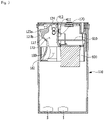
- FIG. 1 is a perspective view of a content receiving mechanism equipped with a passing device according to a first or second embodiment of the present invention
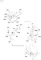
- FIG. 2 is an exploded perspective view of the content receiving mechanism equipped with the passing device according to the first embodiment of the present invention.
- FIG. 3 is a side cross-sectional view of the content receiving mechanism equipped with the passing device according to the first embodiment of the present invention
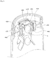
- FIG. 4 is a main part view illustrating an inclination state of a passing movement unit of the passing device according to the first embodiment of the present invention.
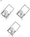
- FIG. 5 shows side cross-sectional views illustrating changes in posture and position of content and the passing device according to an angle change when the content receiving mechanism equipped with the passing device according to the first embodiment of the present invention is tilted.
- FIG. 6 is a cross-sectional view illustrating an example of an installation structure of a detection unit according to the first embodiment of the present invention and illustrates a case in which a single light emitting unit and a single light receiving unit are provided.
- a content receiving mechanism 1 equipped with a passing device 100 includes a housing 110, and the passing device 100 that is installed in the housing 110 to control the passage of content and detect whether the content is discharged.
- the housing 110 is a container for accommodating or storing content 5, and includes a container body 117 which is a portion for receiving and storing the content 5 and a passing device entry part 116 in which the passing device 100 is mounted.
- An opening which is formed on an upper portion of the container body 117 and connected to an interior of the container body is included inside the passing device entry part 116.
- the passing device entry part 116 may be formed to extend from the upper portion of the container body 117, and a screw thread for coupling a container lid 30 may be formed on an outer circumferential surface of the passing device entry part 116.
- the content 5 is solid content, powder content, or the like, and is accommodated in an inner space of the container body 117 in which the passing device 100 is mounted.
- the passing device 100 includes a passing operation unit 120 and a passing movement unit 123.
- the passing operation unit 120 includes a fixing member 121 fixedly coupled to the passing device entry part 116.
- the fixing member may serve to block the opening, wherein an opening 122 may be formed in one region of the fixing member 121 to allow the content to pass therethrough, and the content may pass through the opening 122 and be discharged from the container body to the outside.
- an edge part may be formed on an outer circumferential surface of the fixing member 121, and the outer circumferential surface of the fixing member 121 may be mounted on an inner circumferential surface of the passing device entry part 116 formed on an upper portion of the housing 110 in a screw joining method.
- the passing device of the present invention is detachably coupled to the housing.
- the passing device 100 may be coupled to the housing in various ways such as by adhesion, fusion, and the like, and does not necessarily have to be detachable.
- a duct-shaped passage portion 172 that forms a movement path for discharging a fixed amount of the content 5 and a guide passage 182 that is connected to the passage portion 172 to guide the content are formed under the opening 122 of the fixing member 121.
- the content is moved from the container body 117 to the passage portion 172 through the guide passage 182 and discharged to the outside through the opening 122.
- An inner diameter of one side of the guide passage 182 is gradually increased downward so that the one side of the guide passage 182 is almost in close contact with an inner wall of the container body 117.
- the passage portion 172 is formed by a sidewall 170 extending downward to be adjacent to the opening 122 of the fixing member 121 and by the passing movement unit 123.
- the passing movement unit 123 includes an opening member 124 that blocks the opening, a rotation shaft 125 serving as a center of a rotational movement, and a blocking member 127 that is connected to the rotation shaft and rotated together with the opening member.
- the rotation shaft 125 is installed in a holding part of the rotation shaft 125, which is formed in the fixing member, and the opening member 124 blocks at least a portion of the opening 122 to close the passage portion 172 with respect to the outside of the housing 110 in a normal state in which the receiving mechanism is erected, wherein, when the content pushes the opening member by gravity while the receiving mechanism is tilted at a certain angle or more, the opening member 124 is rotated about the rotation shaft 125 so that the opening 122 is opened, and thus the content passes through the opening 122 to be discharged to the outside.
- the configuration and operation of the passing movement unit 123 will be described below in detail with reference to FIGS. 4 and 5 .
- the passing movement unit 123 together with the sidewall 170 forms the passage portion 172 in a normal state.
- the sidewall 170 forms three sidewalls of the passage portion 172 and the passing movement unit forms one side wall.
- a guide portion 180 forming the guide passage 182 has a curved shape and the content is moved in the guide passage formed by the guide portion by frictional movement along the guide portion. Thereafter, the content is introduced into the passage portion 172 through the guide passage 182, and then is discharged to the outside through the opening at an upper end of the passage portion.
- the guide passage 182 is formed by the guide portion 180 extending to be adjacent to the inner wall of the container body 117, guide members 190 formed at both sides of the guide portion, and a resistance upper plate member disposed to face the guide portion 180.
- Internal cross-sectional areas of the passage portion 172 and the guide passage 182 and a size and shape of the passing movement unit are designed according to a size and shape of the content which is accommodated in the receiving mechanism and discharged in a fixed amount through the passing device 100.
- the above configuration is for discharging a fixed amount of content, and the opening member 124 and the blocking member 127 are connected to each other with the rotation shaft interposed therebetween and extend to have a predetermined angle, as illustrated in FIGS 3 and 4 .
- the "fixed amount” refers to the same number or amount, or refers to an amount or number that is moved differently within an error and allowable range.
- the "demand amount” refers to an amount (number) required by the user and is included in the category of the fixed amount.
- the sizes and angles of the opening member 124 and the blocking member 127 and the size of the movement path of the content are designed in order to control the movement and discharge of content in an exactly desired amount.
- the fixed amount is one
- another piece of content 5 is adjacent to a rear of the content 5 that had passed through the front of the passage portion 172, and passes through a rear of the passage portion 172, and the content 5 that had passed through the rear of the passage portion 172 is moved and brought into contact with the blocking member 127.
- the blocking member 127 may be formed to be bent, and a blocking member bent part 127b of the blocking member 127 may be bent linearly or may be formed as a curved surface.
- the blocking member bent part 127b formed to have an angle by bending the blocking member 127 may be configured to have a steep slope close to a right angle to prevent the content exceeding the demand amount from entering an inside of the passing operation unit 120.
- the blocking member bent part 127b may be bent at any one of various other angles.
- the blocking member 127 blocks at least portion of the passage portion 172 to prevent the content 5 exceeding the fixed amount from being introduced into the passage portion 172.
- a state in which the opening member 124 is blocking the opening 122 may be maintained by an action of a force of weight balance of the passing movement unit 123 or by a stopper 129 of the passing movement unit 123.
- the stopper 129 prevents the passing movement unit 140 from being rotated in the clockwise direction.
- the opening member 124 blocks the opening 122, and thus foreign substances such as air, dust, and the like are suppressed from entering an inner side of the housing 110 through the opening 122.
- a position and shape of the stopper 129 may be variously designed to have the above function.
- the stopper 129 may be formed on one side of the fixing member, which is adjacent to the opening 122.
- the detection unit which will be described below may be disabled. Since power loss occurs when the detection unit continues to operate, a separate motion sensor is mounted to reduce an amount of power, and when the motion sensor is operated, the detection unit may be switched from a standby state to an operating state.
- FIG. 4 shows a state of the passing movement unit 123 when the housing 110 is tilted to guide the passage of the content 5.
- the passing movement unit 123 is rotated (moved) in both directions with respect to the rotation shaft 125 as a reference C.
- FIG. 5 shows (a) a state in which the receiving mechanism in the initial state is tilted at a predetermined angle, for example, 135 degrees, in a counterclockwise direction, (b) a state of the passing movement unit 123 in which the content is brought into contact with the opening member 124 by further tilting the receiving mechanism and starts to apply a force to the opening member 124, and (c) a state in which the content is discharged and next content that is positioned at a rear (upstream side) of the discharged content is blocked by the blocking member 127.
- a predetermined angle for example, 135 degrees
- the passing movement unit 123 is moved in response to the movement of the content by the action of gravity, and opens the passing operation unit 120 so that the content passes therethrough.
- the passing movement unit 123 may be moved by at least one of the weight of the passing movement unit 123, the inertia of the passing movement unit 123, and the force of the content pressing the passing movement unit 123.
- the rotational movement of the passing movement unit 123 for passing the content is performed by, while the rotation shaft 125 of the passing movement unit 123 positioned in a downward direction, which is a direction of gravity, gravity movement of the content or a kinetic force of the content being transferring to the passing movement unit 123 by the movement of the passing operation unit 120 being tilted, inverted, or shaken.
- the rotational movement of the passing movement unit 123 is performed by the kinetic force according to pressing of the weight of the content.
- the center of gravity of the passing movement unit 123 is positioned in a direction (upstream side in the movement path of the content) opposite to an external passing direction of the passing device 100, which is a rearward direction of the position of the rotation shaft 125 of the passing movement unit 123.
- the passing operation unit 120 coupled to the receiving mechanism is tilted by the inclination of the receiving mechanism 1, the rotational movement of the passing movement unit 123 may be inhibited or delayed due to a difference in position between the center of gravity of the passing movement unit and the rotation shaft 125.
- the passing movement unit 123 may include a motion control member 123a, and a balance unit 123b that suppress the passing movement unit 123 from being tilted together with the passing operation unit 120.
- a weighted force in a direction opposite to the inclination direction of the passing operation unit 120 acts on the passing movement unit 123, and thus the opening member 124 is tilted by the weight of the opening member 124 to suppress the opening 122 from being opened.
- the rotation of the blocking member 127 included in the passing movement unit 123 is prevented, and thus the passage of the content that is introduced into the passage portion 172 is maintained without change.
- the balance unit 123b is configured to generate a force that rotates in a direction opposite to a direction of a slope of the passing operation unit 120, in which a weight balance state of the balance unit 123b is tilted to pass the content 5 therethrough, and thus the opening member 124 is not bent in the direction of the slope of the passing operation unit 120 by the weight balance of the balance unit 123b, and the force that rotates in the direction opposite to the direction of the slope of the passing operation unit 120 acts.
- the direction of the force that is intended to rotate in order for the passing movement unit 123 or the balance unit 123b to maintain equilibrium or to achieve equilibrium is generated by the force to rotate the passing movement unit 123 or the balance unit 123b in the direction opposite to the direction of the slope of the content receiving mechanism or the receiving mechanism 1.
- the passing movement unit 123 may further include a motion control member 123a that does not face the passage portion 172 for balancing the center of gravity of the passing movement unit 123.
- a minimum inner diameter L1 of the passage which is a minimum length of an inner diameter of the inner space of the passage portion 172, is less than or equal to twice a maximum outer diameter L2 of the content in a short direction, which is a maximum length of an outer diameter in the short direction of the piece of content 5, and thus two or more pieces of content 5 cannot enter or pass through a passing passage 139 simultaneously, and only one piece of content 5 is allowed to enter or pass through the passing passage 139 at one time.
- the passage portion 172 guides the content 5 to pass through the passage portion 172 in a longitudinal direction of the length of the end in a long direction.
- the detection unit includes one or more light emitting units installed on one side of the passage portion 172, which is a moving passage that is formed in the passing operation unit and discharges the content, and one or more light receiving units installed on another side of the moving passage facing the one side on which the light emitting units are installed.
- the light emitting units are formed on one side of the sidewall 170 forming the passage portion 172, and the light receiving units are formed on another side facing the one side of the sidewall.
- FIG. 6 is a cross-sectional view illustrating an example (case in which a single light emitting unit and a single light receiving unit are provided) of an installation structure of the detection unit in the passing device according to the first embodiment of the present invention.
- a light emitting unit 420 is installed on one side of the sidewall 170 coupled to extend to a lower portion of the fixing member.
- the light emitting unit 420 may be installed on a support part 440 which is formed to protrude to the outside of one side of the sidewall.
- a passing through part 450 may be formed in the passing operation unit 120 so that light emitted from the light emitting unit 420 may be emitted to the passage portion 172.
- a light receiving unit 410 is installed on a support part 440 of another side of the sidewall 170 to receive the light emitted from the light emitting unit 420. It is sufficient that the light emitting unit and the light receiving unit are disposed to face each other with the passage portion interposed therebetween, and the light emitting unit and the light receiving unit may be installed at positions other than that of the support part 440.
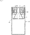
- FIG. 7 is a cross-sectional view illustrating another example of the installation structure of the detection unit in the passing device according to the first embodiment of the present invention, and illustrates a structure in which a detection unit having two light emitting units and two light receiving units is provided.
- Two photodiodes installed on one side of the passage portion are arranged in a line along the movement path of the content of the passage portion 172.
- the light receiving units composed of two photodiodes are arranged on one side of the sidewall 170 forming the passage portion 172 in a line along the movement path of the content.
- two light receiving units 411 and 412 may be vertically arranged in a line in a through hole formed in one side of the sidewall 170 forming the passage portion 172, and a transmission wall through which light can be transmitted may be disposed between the through hole and the passage portion 172.
- the light emitting units are disposed on another side of the sidewall 170 forming the passage portion 172 to face the light receiving units.
- the light emitting units emit light toward the content, and the light receiving units receive the light emitted from the light emitting units.
- two light emitting units may be vertically arranged in a line on the outside of the passage portion 172 and in the through hole formed in the sidewall 170, and the transmission wall through which light can be transmitted may be disposed between the through hole and the passage portion 172.
- the two light receiving units 411 and 412 and the two light emitting units are physically and electrically connected and fixed to a printed circuit board (PCB) 810 couple to the fixing member.
- PCB printed circuit board
- the detection unit includes at least one light emitting unit that emits light, at least one light receiving unit that receives the light emitted from the light emitting unit, and a sensing control unit.
- the sensing control unit controls the light emitting unit and the light receiving unit, and processes an optical signal which is received by the light receiving unit after being emitted from the light emitting unit.
- the sensing control unit may be implemented with a microcontroller unit (MCU), a field programmable gate array (FPGA), or the like, and may be physically included in the PCB 810.
- the passing device may further include a communication module.
- FIG. 8 is a block diagram of a detection unit that detects a movement of content according to an embodiment of the present invention.
- two light emitting diodes LEDs
- LEDs particularly, infrared LEDs
- Light receiving units IR1 and IR2 are photodiodes capable of detecting infrared light, and are arranged in a line along the path of the passage portion at positions facing the two LEDs.
- the light receiving units are satisfied as long as they are light sensing elements capable of sensing light and are not limited to photodiodes.
- the light receiving units are composed of first and second light receiving units, wherein a first light receiving unit 411 or IR1 is disposed on a relatively lower portion of the passage portion 172, that is, at an upstream side in the movement path of the content, and a second light receiving unit 412 or IR2 is disposed on a relatively upper portion of the passage portion 172, that is, at a downstream side in the movement path of the content.
- the light emitting units are composed of one or more light emitting elements, and may be composed of two light emitting elements. Although both two light emitting elements may be turned on to irradiate the passage portion with light, only one of the two light emitting elements may be in an ON state. Alternatively, one light emitting element is disposed to face the two light receiving units and disposed at an intermediate position of the two light receiving units. The light emitted from the light emitting unit crosses the passage portion and is detected by the light receiving unit. When the content passes therethrough, the light emitted from the light emitting unit is blocked by the content, and thus it is detected that an amount of light is temporarily small.
- FIG. 9 shows schematic views illustrating change patterns of an amount of light measured by a detection unit having two light receiving units for detecting a movement of content of the present invention.
- An amount of light detected by each of two light receiving units IR1 and IR2 has an analog value, and an analog-to-digital converter (ADC) converts the analog value into a digital value to obtain a sampling value.
- a sensing control unit may detect whether a tablet passes therethrough using the sampling value. When a gap between the light emitting unit and the light receiving unit is blocked with the tablet, the amount of the received light is reduced, and thus the sampling value is also reduced at a moment the tablet passes.
- a horizontal axis represents time
- a vertical axis represents the sampling value obtained by converting, by the ADC, the amount of the light detected by each of the first light receiving unit IR1 and the second light receiving unit IR2 into a digital value.
- the success or failure of the discharge may be determined by comparing a waveform of the light detected by the first light receiving unit IR1 and a waveform of the light detected by the second light receiving unit IR2 over time in case of success or failure of discharge.
- the amount of the light detected by the first light receiving unit IR1 or 411 is changed from a state of falling within a first standard light amount range to a first reference light amount or less and then enters the first standard light amount range again, it is determined that the content has passed through the first light receiving unit region.
- the amount of the light detected by the second light receiving unit IR2 or 412 is changed from a state of falling within a second standard light amount range to a second reference light amount or less and then enters the second standard light amount range again, it is determined that the content has passed through the second light receiving unit region.
- the first standard light amount range and the second standard light amount range are ranges of the amount of the light detected by the first light receiving unit and the second light receiving unit, respectively, in a state in which the content does not pass therethrough.
- Such a determination process may be performed by the sensing control unit included in the detection unit of the passing device or may be performed by a processor or the like included in the receiving mechanism, but the present invention is not limited thereto.
- the ADC may convert the analog value of the amount of the detected light
- a wired or wireless communication module may transmit the converted value to an external server or terminal, and thus the external terminal or server may perform the determination process.
- an external terminal or server may be a medication management terminal or a medication management server.
- the inventors of the present invention obtain the following specific experimental results by repeating the experiment several times.
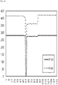
- FIG. 10 is a graph showing a change in an amount of light in the case in which a relatively large and long tablet passes through a passage portion and then is discharged to the outside, when the receiving mechanism equipped with the passing device in which two light emitting elements are arranged is tilted according to the first embodiment of the present invention. In this case, only one light emitting element disposed on a side close to the opening 122 among the two light emitting elements is in an ON state.
- an amount of light detected by a first light receiving unit is indicated by a solid line
- an amount of light detected by a second light receiving unit is indicated by a dotted line.
- an amount of light detected by a first light receiving unit is indicated by a solid line
- an amount of light detected by a second light receiving unit is indicated by a dotted line.
- An amount of light detected by a first light receiving unit IR1 is maintained within a first standard light amount range (e.g., 250 to 300) substantially constant because content does not pass therethrough at the beginning. Thereafter, when the receiving mechanism is tilted, the content enters the passage portion 172, passes through the first light receiving unit region first, and rotates the opening member of the passing movement unit while pushing the opening member of the passing movement unit, and thus the content passes through the opening 122 and is discharged. Accordingly, the amount of the light is changed to the first reference light amount or less and then enters the first standard light amount range again.
- a first standard light amount range e.g. 250 to 300
- the amount of the light detected by the second light receiving unit IR2 disposed at the further downstream side of the passage portion is in a state of falling within the second standard light amount range (350 to 450), is changed to the second reference light amount (in this case, 10) or less, and then enters the second standard light amount range again.
- a time, at which the amount of the light detected by the first light receiving unit is restored back to the first standard light amount range is the same as or slightly earlier than a time, at which the amount of the light detected by the second light receiving unit is restored to a value within the second standard light amount range.
- a waveform of the light is observed when the content is successfully discharged.
- the amount of the light detected by the first light receiving unit IR1 is indicated by a solid line
- the amount of the light detected by the second light receiving unit IR2 is indicated by a dotted line.
- the displayed amount of light detected by the first light receiving unit is maintained within the first standard light amount range (e.g., 250 to 300) substantially constant because content does not pass therethrough at the beginning. Thereafter, the content enters the passage portion 172 by tilting the receiving mechanism at a slope exceeding a predetermined slope and such a state continues for a considerable period of time.
- the amount of the light is maintained for a relatively long period of time for which the amount of the light becomes the first reference light amount or less, for example, 10 or less, and then enters the first standard light amount range again.
- the amount of the light is within the first standard light amount range, is changed to the second reference light amount (in this case, 50) or less, and then enters the second standard light amount range again.
- the second reference light amount in this case, 50
- a time at which the amount of the light detected by the first light receiving unit is restored back to the first standard light amount range is later than a time for which the amount of the light detected by the second light receiving unit is restored to a value within the second standard light amount range.
- the waveform of the light is observed when the content cannot be successfully discharged and returns into the housing of the receiving mechanism.
- the passing movement unit including the blocking member does not block the passage portion, as illustrated in FIGS. 5A and 5B . Therefore, a change in amount of light caused thereby does not significantly affect a detection signal.
- a predetermined period of time T2 for which a state in which an amount of light detected in case of failure of discharge is less than or equal to a set reference light amount is maintained is longer than a period of time T1 for which a state in which an amount of light detected in case of success of discharge is less than or equal to the set reference light amount is maintained.
- the predetermined period of time T2 is two or more times longer than the period of time T1 for which the state in which the amount of the light is less than or equal to the reference light amount in case of success of discharge of the content is maintained.
- the second embodiment is a configuration of the passing device when content is relatively small.
- a passing movement unit 123 including a blocking member 127 blocks a considerable portion of the passage portion, as illustrated in FIG. 13B and 13C . Therefore, a change in amount of light caused thereby does significantly affect a detection signal.
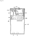
- FIG. 12 is a cross-sectional view of the content receiving mechanism equipped with the passing device according to the second embodiment of the present invention for passage of a relatively small tablet.
- the passing movement unit according to the second embodiment of the present invention allows a relatively small content (tablet) in a fixed amount to pass therethrough, wherein the motion control member 123a and the blocking member 127 are integrally formed for appropriate weight distribution, and thus a portion disposed on a lower side of the passing movement unit, that is, at an upstream side of the passage portion 172, has a relatively thick shape.
- the blocking member 127 is formed to be small and thick, and thus the motion control member 123a having an arc shape in which a rear surface of the blocking member is cut is formed.
- the configuration of the second embodiment except for the passing movement unit is substantially the same as that of the first embodiment, except that there is a difference in size and the like.
- the configuration of the detection unit of the second embodiment particularly, the configuration of the first and second light receiving units, is the same as that of the first embodiment, except that the dimensions and intervals may be changed according to the size of the content. The same description as in the first embodiment will be omitted.
- FIG. 13 shows cross-sectional views illustrating changes in position and posture of content and the passing device according to a change in angle when the content receiving mechanism equipped with the passing device according to the second embodiment of the present invention is tilted.
- the blocking member 127 and the motion control member 123a occupy a considerable portion of the passage portion 172 because their side cross-sections are integrally formed to be close to a triangle.
- FIGS. 14 and 15 are graphs showing changes in amount of light over time in case of success and failure of discharge in a state in which only an LED positioned at a downstream side of the passage portion among the light emitting units composed of two LEDs is turned on.
- FIG. 14 is a graph showing, when the receiving mechanism equipped with the passing device according to the second embodiment of the present invention is tilted, a change in amount of light over time when a tablet is discharged in the case that two light emitting elements are arranged in the passing device according to the second embodiment of the present invention.
- An amount of the light detected by the first light receiving unit IR1 is maintained within a first standard light amount range (e.g., 200 to 250) substantially constant because the content does not pass through at the beginning. Thereafter, when the receiving mechanism is tilted, the content enters the passage portion 172, and the amount of the light is changed to a first reference light amount or less, for example, 30 or less, and then enters the first standard light amount range again.
- a first standard light amount range e.g. 200 to 250
- the amount of the light detected by the second light receiving unit disposed at the downstream side of the passage portion is within a second standard light amount range (300 and 400), is changed to a second reference light amount (in this case, 30) or less, and then enters the second standard light amount range again.
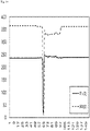
- FIG. 15 is a graph showing, when the receiving mechanism equipped with the passing device according to the second embodiment of the present invention in which two light emitting elements are arranged is tilted, a change in amount of light over time when a relatively small tablet fails to be discharged.
- the amount of the light detected by the first light receiving unit IR1 is about 300 uniform at the beginning, is positioned at a low value for a considerable period of time, that is, a value in a range of approximately 1 to 160, reaches a value of 50 or less again, and then enters the first standard light amount range again.
- the amount of the light detected by the second light receiving unit disposed at the further downstream side of the passage portion is within the second standard light amount range (450 to 500), is changed to the second reference light amount (in this case, 50) or less, and then enters the second standard light amount range again.
- a predetermined period of time T2 for which a state in which the amount of light detected in case of failure of discharge as in FIG. 15 is less than or equal to the set reference light amount is maintained is longer than a period of time T1 for which a state in which the amount of light detected in case of success of discharge as in FIG. 14 is less than or equal to the set reference light amount is maintained.
- the predetermined period of time T2 is two or more times longer than the period of time T1 for which the state in which the amount of the light is less than or equal to the reference light amount in case of success of discharge is maintained.
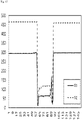
- FIG. 16 is a graph showing, when the receiving mechanism equipped with the passing device according to the second embodiment of the present invention in which two light emitting elements are arranged is tilted, a change in amount of light over time when a relatively small tablet is successfully discharged.
- the amount of light detected by the first light receiving unit IR1 is the first standard light amount range (about 300) uniform at the beginning, draws a downward peak (lowest value), is positioned in the third reference range, about 50 to 150 again, and then enters the first standard light amount range again.
- a state is a state in which a thick blocking member is positioned in the passage portion to block the light emitted from the light emitting unit.
- the amount of the light detected by the second light receiving unit disposed at the downstream side of the passage portion is in a state of falling within the second standard light amount range (400 to 500), is changed to the second reference light amount (in this case, 50) or less, and then enters the second standard light amount range again.
- FIGS. 17 to 19 are graphs showing changes in amount of light detected by the first and second light receiving units when both two arranged LEDs are turned on.
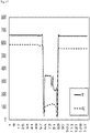
- FIG. 17 is a graph showing, when the receiving mechanism equipped with the passing device according to the second embodiment of the present invention in which two light emitting elements are arranged is tilted, a change in amount of light over time when a relatively small tablet fails to be discharged.
- the amount of the light detected by the first light receiving unit IR1 falls within a range of 600 to 720 (the first standard light amount range) at the beginning, is positioned at a first reference value (1 to 360), reaches the lowest value again, and then enters the first standard light amount range again.
- the amount of the light detected by the second light receiving unit disposed at the further downstream side of the passage portion is in a state of falling within the second standard light amount range (540 to 700), is changed to the second reference light amount (in this case, 180) or less, and then enters the second standard light amount range again.
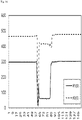
- FIG. 18 is a graph showing, when the receiving mechanism equipped with the passing device according to the second embodiment of the present invention in which two light emitting elements are arranged is tilted, a change in amount of light over time when a relatively small tablet is successfully discharged.
- the amount of the light detected by the first light receiving unit is rapidly decreased in a section of falling within the first standard light amount range (600 to 700), and is maintained in for a relatively long period of time in a section of falling within the third range (300 to 350) again and in a section of being the first reference value (100) or less, and then the amount of the light enters the first standard light amount range (600 to 700) again.
- the third range refers to a situation in which the passing movement unit including the blocking member partially blocks the light.
- the amount of the light detected by the second light receiving unit disposed at the further downstream side of the passage portion is in a state of falling within the second standard light amount range (550 to 600), is changed to the second reference light amount (in this case, 50) or less, is maintained in a fourth range for a considerable period of time, and then enters the second standard light amount range again.
- the second standard light amount range 550 to 600
- a time at which the first light receiving unit reaches the third range is earlier than a time at which the second light receiving unit reaches the fourth range, and in this case, it is determined that the content has been successfully discharged.
- the third and fourth ranges refer to situations in which the passing movement unit including the blocking member partially blocks the light.
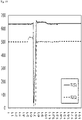
- FIG. 19 is a graph showing, when the receiving mechanism equipped with the passing device according to the second embodiment of the present invention in which two light emitting elements are arranged is tilted, a change in amount of light over time when a relatively small tablet is successfully discharged.
- This case corresponds to the most common case, and a time at which the amount of the light detected by the first light receiving unit IR1 is in a state of falling within the first standard light amount range, reaches the lowest value of the first reference value or less, and then enters the first standard light amount range again is earlier than a time at which the amount of the light detected by the second light receiving unit IR2 reaches the lowest value and then enters the second standard light amount range again. That is, that is, the amount of light detected by the first light receiving unit IR1 returns to its original state first.
- the amount of the light reaches the downward peak in the standard section and then the times at which the value of the standard section is detected again are compared to determine whether the content passes therethrough.
- the reference value may be a value in which the amount of the light falls within the first or second standard light amount range, but the present invention is not limited thereto, and another value may be determined as the reference value.
- the user or the like may arbitrarily inject the content from the outside, and since this process changes the amount of content accommodated in the container, the amount of content may be measured.
- the discharge of the content and the signal patterns of the first and second light receiving units reversely appear. That is, a pattern that appears temporally later than the downward peak of the signal detected by the first light receiving unit inside the passage or the downward signal peak of the second light receiving unit is shown.
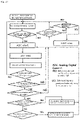
- FIG. 20 is a flowchart of a process of determining whether content is discharged according to an embodiment of the present invention.
- a passing device or a receiving mechanism equipped with the passing device further include a motion sensor.
- the motion sensor may detect both a movement and a slope, it is sufficient that a motion sensor and an inclination sensor are each provided to detect the movement and the slope of the receiving mechanism or the passing device.
- the motion sensor detects the movement of the receiving mechanism including the passing device and a data value is read. Thereafter, when it is detected that the slope of the container is greater than or equal to about 90 degrees, the detection unit including the first and second light receiving units and the light emitting unit and the ADC are activated. This is to save power consumption by preventing unnecessary sensor operation. When the slope of the container is less than about 90 degrees, the detection unit and the like are deactivated, and the motion sensor returns back to the movement detection mode.
- the motion sensor detects the movement
- the data value is read, and in this case, when it is detected that the slope of the container is greater than or equal to 90 degrees, the ADC is activated.
- the ADC processes the value detected by the motion sensor, and when it is detected that the slope is greater than or equal to 90 degrees, each of the first and second light receiving units is activated to detect a signal.
- the slope of the container is not 90 degrees or more, the light receiving units are not activated, and the motion sensor returns back to a mode for detecting the slope of the motion sensor.
- each of the first detection unit and the second detection unit detects the passage of the content, that is, the penetration.
- the first light receiving unit detects the penetration before the second light receiving unit, it is determined that the content is normally discharged
- the second light receiving unit detects the penetration before the first light receiving unit, it is determined that the content has failed to be discharged. This process is done in a processor after the ADC's signal sampling.
- the sensing control unit processes the amount of light signal detected by the light receiving unit according to the time, generates medication status information according to a result of whether the content passes therethrough, and transmits the generated medication status information to a medication guide terminal 600 through a communication module 500.
- the sensing control unit generates the medication status information on the basis of a detection result of the content 5, and transmits the generated medication status information to the medication guide terminal 600.
- the medication status information includes information about the content 5, information about whether the content 5 is detected, information about a detection time at which the content 5 is detected, and the like.
- the information about the content 5 may be preset in the sensing control unit or the like, and the information about whether the content 5 is detected and the information about a detection time at which the content 5 is detected may be detected in real time according to whether the content 5 is detected by the detection unit.
- the medication guide terminal 600 receives the medication status information from the sensor module 500, receives medication schedule information from a medication management server 700, generates medication management information using the medication schedule information and the medication status information, and then outputs the generated medication management information.
- the medication guide terminal 600 includes an external signal input unit 610, a control unit 630, and an output unit 620.
- the present invention it is possible to accurately detect an amount of content discharged from a receiving mechanism, and it is possible to allow a user to take a fixed amount of medications on the basis of the detected amount of the content.
Landscapes
- Health & Medical Sciences (AREA)
- Life Sciences & Earth Sciences (AREA)
- Engineering & Computer Science (AREA)
- Animal Behavior & Ethology (AREA)
- General Health & Medical Sciences (AREA)
- Public Health (AREA)
- Veterinary Medicine (AREA)
- Mechanical Engineering (AREA)
- Medical Informatics (AREA)
- Physics & Mathematics (AREA)
- General Physics & Mathematics (AREA)
- General Life Sciences & Earth Sciences (AREA)
- Geophysics (AREA)
- Spectroscopy & Molecular Physics (AREA)
- Pharmacology & Pharmacy (AREA)
- Medical Preparation Storing Or Oral Administration Devices (AREA)
- Geophysics And Detection Of Objects (AREA)
Applications Claiming Priority (2)
| Application Number | Priority Date | Filing Date | Title |
|---|---|---|---|
| KR1020190169241A KR102157445B1 (ko) | 2019-12-17 | 2019-12-17 | 통과 장치, 통과 장치를 구비한 내용물 수용 기구, 복약 관리 장치 및 내용물의 토출 여부를 판정하는 방법 |
| PCT/KR2020/018510 WO2021125817A1 (ko) | 2019-12-17 | 2020-12-17 | 통과 장치, 통과 장치를 구비한 내용물 수용 기구, 복약 관리 장치 및 내용물의 토출 여부를 판정하는 방법 |
Publications (4)
| Publication Number | Publication Date |
|---|---|
| EP4079658A1 true EP4079658A1 (de) | 2022-10-26 |
| EP4079658A4 EP4079658A4 (de) | 2023-10-18 |
| EP4079658C0 EP4079658C0 (de) | 2025-03-05 |
| EP4079658B1 EP4079658B1 (de) | 2025-03-05 |
Family
ID=72707199
Family Applications (1)
| Application Number | Title | Priority Date | Filing Date |
|---|---|---|---|
| EP20903392.7A Active EP4079658B1 (de) | 2019-12-17 | 2020-12-17 | Passiervorrichtung, inhaltsempfangsmechanismus mit passiervorrichtung, medikamentenverwaltungsvorrichtung und verfahren zum bestimmen, ob der inhalt ausgegeben werden soll oder nicht |
Country Status (6)
| Country | Link |
|---|---|
| US (2) | US20230036333A1 (de) |
| EP (1) | EP4079658B1 (de) |
| JP (2) | JP2023507633A (de) |
| KR (1) | KR102157445B1 (de) |
| CN (2) | CN114929595A (de) |
| WO (1) | WO2021125817A1 (de) |
Cited By (1)
| Publication number | Priority date | Publication date | Assignee | Title |
|---|---|---|---|---|
| EP4424611A1 (de) * | 2023-02-17 | 2024-09-04 | CVS Pharmacy, Inc. | Abgabevorrichtung und modularer spender |
Families Citing this family (16)
| Publication number | Priority date | Publication date | Assignee | Title |
|---|---|---|---|---|
| KR102157445B1 (ko) * | 2019-12-17 | 2020-09-17 | 박경도 | 통과 장치, 통과 장치를 구비한 내용물 수용 기구, 복약 관리 장치 및 내용물의 토출 여부를 판정하는 방법 |
| KR102395334B1 (ko) * | 2021-05-13 | 2022-05-09 | 박경도 | 내용물의 정량 토출장치 및 이를 구비하는 보관용기 |
| USD1005108S1 (en) * | 2021-05-21 | 2023-11-21 | Brillian Pharma LLC | Unit dose container |
| US11723842B2 (en) * | 2021-09-30 | 2023-08-15 | Blueberry Pill Dispenser Public Benefit LLC | Systems and methods for medication dispenser |
| WO2025065064A1 (en) * | 2023-09-29 | 2025-04-03 | Cloud Wally Robert | Modular and automated dispenser for discrete objects |
| KR102935896B1 (ko) * | 2024-01-05 | 2026-03-09 | (주)콜러디 | 통과장치, 통과장치를 구비한 내용물 수용기구 및 내용물 토출 판정 방법 |
| US12268656B1 (en) * | 2024-03-08 | 2025-04-08 | Aspargo Laboratories, Inc. | Medication dispensing system with keyed medication cartridge |
| US12409279B1 (en) | 2024-03-08 | 2025-09-09 | Aspargo Laboratories, Inc. | Handheld oral medication dispensing device with activator mechanism |
| US12106836B1 (en) | 2024-03-15 | 2024-10-01 | Aspargo Laboratories, Inc. | Biometrcially controlled handheld oral medication dispensing device |
| US12512200B2 (en) | 2024-03-08 | 2025-12-30 | Aspargo Laboratories, Inc. | Medication cartridge |
| US12280014B1 (en) | 2024-03-11 | 2025-04-22 | Aspargo Laboratories, Inc. | Keyed medication cartridge for use in a handheld oral medication dispensing device |
| US20250288494A1 (en) * | 2024-03-15 | 2025-09-18 | Aspargo Laboratories, Inc. | Rechargeable handheld oral medication dispensing device |
| US20250288498A1 (en) * | 2024-03-15 | 2025-09-18 | Aspargo Laboratories, Inc. | Wirelessly controlled handheld oral medication dispensing device |
| US12347541B1 (en) | 2024-03-22 | 2025-07-01 | Aspargo Laboratories, Inc. | Caregiver system and method for interfacing with and controlling a medication dispensing device |
| US12478558B2 (en) | 2024-03-22 | 2025-11-25 | Aspargo Laboratories, Inc. | Physician system and method for interfacing with and controlling a medication dispensing device |
| US12482546B2 (en) | 2024-03-22 | 2025-11-25 | Aspargo Laboratories, Inc. | Patient system and method for interfacing with and controlling a medication dispensing device |
Family Cites Families (56)
| Publication number | Priority date | Publication date | Assignee | Title |
|---|---|---|---|---|
| US3258153A (en) * | 1964-11-12 | 1966-06-28 | Morgan | Dispensing devices with audible announcing means |
| US3369697A (en) * | 1966-08-05 | 1968-02-20 | Glucksman John | Programmed medication dispenser |
| US3677437A (en) * | 1970-03-27 | 1972-07-18 | John S Haigler | Pill counting apparatus having chute shifting on predetermined count |
| JPS5846751B2 (ja) * | 1979-03-09 | 1983-10-18 | 松下電器産業株式会社 | 硬貨払出し装置 |
| US4310103A (en) * | 1980-05-09 | 1982-01-12 | Reilly Jr Philip C | Medication dispenser |
| US4573606A (en) * | 1983-09-12 | 1986-03-04 | Kermit E. Lewis | Automatic pill dispenser and method of administering medical pills |
| US4872591A (en) * | 1987-11-19 | 1989-10-10 | Konopka Richard O | Medication dispenser |
| US5148944A (en) * | 1989-09-29 | 1992-09-22 | Health Tech Services Corporation | Interactive medication delivery system for individual pills and caplets |
| US5084828A (en) * | 1989-09-29 | 1992-01-28 | Healthtech Services Corp. | Interactive medication delivery system |
| US5197632A (en) * | 1989-09-29 | 1993-03-30 | Healthtech Services Corp. | Interactive medication delivery system for individual pills and caplets |
| JP3142899B2 (ja) * | 1991-07-05 | 2001-03-07 | 株式会社ソフィア | ゲーム機の遊技球排出装置 |
| US5755357A (en) * | 1995-06-26 | 1998-05-26 | Healthtech Services Corp. | Compact medication delivery systems |
| US5671262A (en) * | 1996-05-06 | 1997-09-23 | Innovation Associates, Inc. | Method for counting and dispensing tablets, capsules, and pills |
| US5768327A (en) * | 1996-06-13 | 1998-06-16 | Kirby Lester, Inc. | Method and apparatus for optically counting discrete objects |
| US5752620A (en) * | 1996-11-13 | 1998-05-19 | Pearson Ventures, L.L.C. | Medication dispenser |
| US6004020A (en) * | 1997-06-11 | 1999-12-21 | Bartur; Meir | Medication dispensing and monitoring system |
| US6785589B2 (en) * | 2001-11-30 | 2004-08-31 | Mckesson Automation, Inc. | Dispensing cabinet with unit dose dispensing drawer |
| US8195328B2 (en) * | 2003-09-19 | 2012-06-05 | Vesta Medical, Llc | Combination disposal and dispensing apparatus and method |
| KR100503000B1 (ko) * | 2003-09-25 | 2005-07-21 | (주)제이브이엠 | 정제 자동분배장치의 정제 감지 장치와 제어방법 |
| GB0411553D0 (en) * | 2004-05-24 | 2004-06-23 | Glaxo Group Ltd | A dispenser |
| WO2006017183A2 (en) * | 2004-07-09 | 2006-02-16 | Automated Merchandising Systems Inc. | Optical vend-sensing system for control of vending machine |
| US20130304255A1 (en) * | 2004-12-11 | 2013-11-14 | Nitesh Ratnakar | System and apparatus for displaying drug interactions on drug storage containers |
| US8985388B2 (en) * | 2004-12-11 | 2015-03-24 | Nitesh Ratnakar | Smart medicine container |
| KR100591519B1 (ko) * | 2005-06-01 | 2006-06-20 | (주)제이브이엠 | 약제 자동 포장기의 알약 투입 감지장치 |
| CN200997591Y (zh) * | 2006-08-25 | 2007-12-26 | 陈建荣 | 智能感应器 |
| US20110060457A1 (en) * | 2007-12-21 | 2011-03-10 | DSM IP ASSETS B.V a corporation | Device for Dispensing Solid Preparations |
| US8224482B2 (en) * | 2008-01-08 | 2012-07-17 | Parata Systems, Llc | Automated pill dispensing systems configured for detecting bottles in output chutes and related methods of operation |
| WO2010048375A1 (en) * | 2008-10-22 | 2010-04-29 | Newzoom, Inc. | Vending store inventory management and reporting system |
| US9046403B2 (en) * | 2010-02-01 | 2015-06-02 | Mallinckrodt Llc | Systems and methods for managing use of a medicament |
| CN102202130A (zh) * | 2010-03-25 | 2011-09-28 | 鸿富锦精密工业(深圳)有限公司 | 具有解锁和锁定功能的电子装置及其解锁和锁定方法 |
| ES2453502T3 (es) * | 2010-04-26 | 2014-04-08 | Koninklijke Philips N.V. | Dispensador de paletinas o cucharillas para máquinas dispensadoras de bebidas |
| US8436291B2 (en) * | 2010-07-29 | 2013-05-07 | Parata Systems, Llc | Automated pill dispensing systems for detecting characteristics of bottles in output chutes using modulated light sources and related methods of operation |
| US9730860B2 (en) * | 2011-11-03 | 2017-08-15 | Pscap, Llc | Pill dispensing assembly |
| US8727180B2 (en) * | 2012-02-02 | 2014-05-20 | Compliance Meds Technologies, Llc | Smart cap system |
| KR101946592B1 (ko) * | 2012-08-02 | 2019-02-11 | 삼성전자주식회사 | 측정 장치 및 측정 방법 |
| US20170337157A1 (en) * | 2012-08-23 | 2017-11-23 | Reagan Inventions, Llc | System and method for monitoring and dispensing doses of medication |
| US8936175B1 (en) * | 2013-02-07 | 2015-01-20 | Michael Song | Locked pill bottle with timed dispense limits |
| US9072652B1 (en) * | 2013-03-29 | 2015-07-07 | Innovation Associates, Inc. | Pill counting and dispensing apparatus with self-calibrating dispenser |
| KR101481967B1 (ko) * | 2013-05-31 | 2015-01-14 | 주식회사 인포피아 | 비정형 정제 디스펜싱 장치 |
| CN106572944A (zh) * | 2014-08-08 | 2017-04-19 | 珀赛普蒂迈德股份有限公司 | 药丸速度与位置传感器 |
| US20160328535A1 (en) * | 2015-05-05 | 2016-11-10 | Jim Patton | Secure Controlled Substance Pill Dispensing Device |
| US9775780B2 (en) * | 2015-10-06 | 2017-10-03 | Kali Care, Inc. | Smart medication container |
| CN105243714A (zh) * | 2015-10-23 | 2016-01-13 | 移康智能科技(上海)有限公司 | 一种智能门锁的锁门方法及系统 |
| KR20170091524A (ko) * | 2016-02-01 | 2017-08-09 | 박서준 | 통과 장치, 밸브, 이를 구비하는 수용 기구, 내용물 이동 기구 및 내용물 기구 |
| TW201743244A (zh) * | 2016-04-18 | 2017-12-16 | 魯米艾克斯公司 | 用於追蹤病人順從性的智慧套環之機械設計 |
| WO2017216634A2 (en) * | 2016-06-17 | 2017-12-21 | Thin Film Electronics Asa | Wireless mechanism for detecting an open or closed container, and methods of making and using the same |
| KR20180010157A (ko) * | 2016-07-20 | 2018-01-30 | 박서준 | 통과 장치 및 복약 관리 장치 |
| WO2018016890A1 (ko) * | 2016-07-20 | 2018-01-25 | 박서준 | 통과 장치 및 복약 관리 장치 |
| TWI675785B (zh) * | 2016-10-02 | 2019-11-01 | 朴序晙 | 分配裝置及內容物移動設備 |
| JP2018084452A (ja) * | 2016-11-22 | 2018-05-31 | セイコーエプソン株式会社 | ガスセル、磁場計測装置、およびガスセルの製造方法 |
| CN110062736A (zh) * | 2016-12-09 | 2019-07-26 | 川崎重工业株式会社 | 食品的保持装置 |
| US11576842B2 (en) * | 2017-07-19 | 2023-02-14 | Coledy Inc. | Passage device and medication dose management device |
| JP2019052826A (ja) * | 2017-09-19 | 2019-04-04 | アイシン精機株式会社 | 温調装置 |
| KR102032794B1 (ko) * | 2018-06-29 | 2019-10-17 | 이산홍 | 식재료를 저장한 복수의 캡슐을 구비한 삼차원 푸드 프린터 |
| KR102157445B1 (ko) * | 2019-12-17 | 2020-09-17 | 박경도 | 통과 장치, 통과 장치를 구비한 내용물 수용 기구, 복약 관리 장치 및 내용물의 토출 여부를 판정하는 방법 |
| US12245990B2 (en) * | 2021-04-22 | 2025-03-11 | Evernorth Strategic Development, Inc. | Portable medication container |
-
2019
- 2019-12-17 KR KR1020190169241A patent/KR102157445B1/ko active Active
-
2020
- 2020-12-17 EP EP20903392.7A patent/EP4079658B1/de active Active
- 2020-12-17 JP JP2022537876A patent/JP2023507633A/ja active Pending
- 2020-12-17 CN CN202080087942.1A patent/CN114929595A/zh active Pending
- 2020-12-17 CN CN202410556711.0A patent/CN118579386A/zh active Pending
- 2020-12-17 WO PCT/KR2020/018510 patent/WO2021125817A1/ko not_active Ceased
- 2020-12-17 US US17/786,525 patent/US20230036333A1/en not_active Abandoned
-
2024
- 2024-05-14 JP JP2024078734A patent/JP2024105538A/ja active Pending
- 2024-11-01 US US18/935,386 patent/US20250057729A1/en active Pending
Cited By (1)
| Publication number | Priority date | Publication date | Assignee | Title |
|---|---|---|---|---|
| EP4424611A1 (de) * | 2023-02-17 | 2024-09-04 | CVS Pharmacy, Inc. | Abgabevorrichtung und modularer spender |
Also Published As
| Publication number | Publication date |
|---|---|
| EP4079658A4 (de) | 2023-10-18 |
| EP4079658C0 (de) | 2025-03-05 |
| KR102157445B1 (ko) | 2020-09-17 |
| JP2024105538A (ja) | 2024-08-06 |
| CN118579386A (zh) | 2024-09-03 |
| WO2021125817A1 (ko) | 2021-06-24 |
| CN114929595A (zh) | 2022-08-19 |
| JP2023507633A (ja) | 2023-02-24 |
| US20250057729A1 (en) | 2025-02-20 |
| US20230036333A1 (en) | 2023-02-02 |
| EP4079658B1 (de) | 2025-03-05 |
Similar Documents
| Publication | Publication Date | Title |
|---|---|---|
| US20250057729A1 (en) | Passing device, content receiving mechanism equipped with passing device, medication management device, and method for determining whether or not to discharge content | |
| US6481180B1 (en) | Solid preparation filling apparatus | |
| US20140353327A1 (en) | Atypical pill dispensing apparatus | |
| CN110944618A (zh) | 通过装置及服药管理装置 | |
| US9105140B2 (en) | Coin hopper | |
| KR101874328B1 (ko) | 통과 장치, 밸브, 이를 구비하는 수용 기구, 내용물 이동 기구 및 내용물 기구 | |
| JP2014120015A5 (de) | ||
| KR102157435B1 (ko) | 복약 관리 장치 | |
| US20070249276A1 (en) | Token image acquiring apparatus and token selecting apparatus for validating tokens | |
| US8381491B2 (en) | Vial lid fastening device and medicine accommodating and removing device | |
| US20240286820A1 (en) | Device for discharging fixed quantity of content, storage container having same and content management system | |
| KR102241567B1 (ko) | 통과 장치 및 복약 관리 장치 | |
| US7043812B1 (en) | Apparatus and method for button indexing in button attaching machine, and method of adjusting the apparatus | |
| JPH07196129A (ja) | ボトル姿勢修正装置 | |
| US20230355477A1 (en) | Blister contents accommodation device, drug administration management system including same, and method for determining whether contents are discharged | |
| KR102935896B1 (ko) | 통과장치, 통과장치를 구비한 내용물 수용기구 및 내용물 토출 판정 방법 | |
| US20150196459A1 (en) | Pill Counting and Conveying Apparatus | |
| JPH09319908A (ja) | コイン払出装置 | |
| KR20230033979A (ko) | 코인 공급기 | |
| JP4359462B2 (ja) | 遊技機用役物及びそれを用いた遊技機 | |
| JP7749893B2 (ja) | 液状体検出装置 | |
| JPS6031691A (ja) | ホッパ−型コイン払出機 | |
| JP7268141B2 (ja) | 液状体検出装置 | |
| JPS62260289A (ja) | 物品計数装置 | |
| JPH0342521Y2 (de) |
Legal Events
| Date | Code | Title | Description |
|---|---|---|---|
| STAA | Information on the status of an ep patent application or granted ep patent |
Free format text: STATUS: THE INTERNATIONAL PUBLICATION HAS BEEN MADE |
|
| PUAI | Public reference made under article 153(3) epc to a published international application that has entered the european phase |
Free format text: ORIGINAL CODE: 0009012 |
|
| STAA | Information on the status of an ep patent application or granted ep patent |
Free format text: STATUS: REQUEST FOR EXAMINATION WAS MADE |
|
| 17P | Request for examination filed |
Effective date: 20220628 |
|
| AK | Designated contracting states |
Kind code of ref document: A1 Designated state(s): AL AT BE BG CH CY CZ DE DK EE ES FI FR GB GR HR HU IE IS IT LI LT LU LV MC MK MT NL NO PL PT RO RS SE SI SK SM TR |
|
| DAV | Request for validation of the european patent (deleted) | ||
| DAX | Request for extension of the european patent (deleted) | ||
| A4 | Supplementary search report drawn up and despatched |
Effective date: 20230914 |
|
| RIC1 | Information provided on ipc code assigned before grant |
Ipc: G01J 1/02 20060101ALI20230908BHEP Ipc: A61J 7/04 20060101ALI20230908BHEP Ipc: A61J 7/00 20060101ALI20230908BHEP Ipc: B65D 83/04 20060101AFI20230908BHEP |
|
| GRAP | Despatch of communication of intention to grant a patent |
Free format text: ORIGINAL CODE: EPIDOSNIGR1 |
|
| STAA | Information on the status of an ep patent application or granted ep patent |
Free format text: STATUS: GRANT OF PATENT IS INTENDED |
|
| INTG | Intention to grant announced |
Effective date: 20241004 |
|
| RAP1 | Party data changed (applicant data changed or rights of an application transferred) |
Owner name: COLEDY INC. |
|
| RIN1 | Information on inventor provided before grant (corrected) |
Inventor name: PARK, KYUNG DO |
|
| GRAS | Grant fee paid |
Free format text: ORIGINAL CODE: EPIDOSNIGR3 |
|
| GRAA | (expected) grant |
Free format text: ORIGINAL CODE: 0009210 |
|
| STAA | Information on the status of an ep patent application or granted ep patent |
Free format text: STATUS: THE PATENT HAS BEEN GRANTED |
|
| AK | Designated contracting states |
Kind code of ref document: B1 Designated state(s): AL AT BE BG CH CY CZ DE DK EE ES FI FR GB GR HR HU IE IS IT LI LT LU LV MC MK MT NL NO PL PT RO RS SE SI SK SM TR |
|
| REG | Reference to a national code |
Ref country code: GB Ref legal event code: FG4D |
|
| REG | Reference to a national code |
Ref country code: CH Ref legal event code: EP |
|
| REG | Reference to a national code |
Ref country code: IE Ref legal event code: FG4D |
|
| REG | Reference to a national code |
Ref country code: DE Ref legal event code: R096 Ref document number: 602020047433 Country of ref document: DE |
|
| U01 | Request for unitary effect filed |
Effective date: 20250401 |
|
| U07 | Unitary effect registered |
Designated state(s): AT BE BG DE DK EE FI FR IT LT LU LV MT NL PT RO SE SI Effective date: 20250407 |
|
| PG25 | Lapsed in a contracting state [announced via postgrant information from national office to epo] |
Ref country code: RS Free format text: LAPSE BECAUSE OF FAILURE TO SUBMIT A TRANSLATION OF THE DESCRIPTION OR TO PAY THE FEE WITHIN THE PRESCRIBED TIME-LIMIT Effective date: 20250605 |
|
| PG25 | Lapsed in a contracting state [announced via postgrant information from national office to epo] |
Ref country code: ES Free format text: LAPSE BECAUSE OF FAILURE TO SUBMIT A TRANSLATION OF THE DESCRIPTION OR TO PAY THE FEE WITHIN THE PRESCRIBED TIME-LIMIT Effective date: 20250305 |
|
| PG25 | Lapsed in a contracting state [announced via postgrant information from national office to epo] |
Ref country code: NO Free format text: LAPSE BECAUSE OF FAILURE TO SUBMIT A TRANSLATION OF THE DESCRIPTION OR TO PAY THE FEE WITHIN THE PRESCRIBED TIME-LIMIT Effective date: 20250605 |
|
| PG25 | Lapsed in a contracting state [announced via postgrant information from national office to epo] |
Ref country code: HR Free format text: LAPSE BECAUSE OF FAILURE TO SUBMIT A TRANSLATION OF THE DESCRIPTION OR TO PAY THE FEE WITHIN THE PRESCRIBED TIME-LIMIT Effective date: 20250305 |
|
| PG25 | Lapsed in a contracting state [announced via postgrant information from national office to epo] |
Ref country code: GR Free format text: LAPSE BECAUSE OF FAILURE TO SUBMIT A TRANSLATION OF THE DESCRIPTION OR TO PAY THE FEE WITHIN THE PRESCRIBED TIME-LIMIT Effective date: 20250606 |
|
| PG25 | Lapsed in a contracting state [announced via postgrant information from national office to epo] |
Ref country code: SM Free format text: LAPSE BECAUSE OF FAILURE TO SUBMIT A TRANSLATION OF THE DESCRIPTION OR TO PAY THE FEE WITHIN THE PRESCRIBED TIME-LIMIT Effective date: 20250305 |
|
| PG25 | Lapsed in a contracting state [announced via postgrant information from national office to epo] |
Ref country code: PL Free format text: LAPSE BECAUSE OF FAILURE TO SUBMIT A TRANSLATION OF THE DESCRIPTION OR TO PAY THE FEE WITHIN THE PRESCRIBED TIME-LIMIT Effective date: 20250305 |
|
| PG25 | Lapsed in a contracting state [announced via postgrant information from national office to epo] |
Ref country code: CZ Free format text: LAPSE BECAUSE OF FAILURE TO SUBMIT A TRANSLATION OF THE DESCRIPTION OR TO PAY THE FEE WITHIN THE PRESCRIBED TIME-LIMIT Effective date: 20250305 |
|
| PG25 | Lapsed in a contracting state [announced via postgrant information from national office to epo] |
Ref country code: SK Free format text: LAPSE BECAUSE OF FAILURE TO SUBMIT A TRANSLATION OF THE DESCRIPTION OR TO PAY THE FEE WITHIN THE PRESCRIBED TIME-LIMIT Effective date: 20250305 |
|
| PG25 | Lapsed in a contracting state [announced via postgrant information from national office to epo] |
Ref country code: IS Free format text: LAPSE BECAUSE OF FAILURE TO SUBMIT A TRANSLATION OF THE DESCRIPTION OR TO PAY THE FEE WITHIN THE PRESCRIBED TIME-LIMIT Effective date: 20250705 |
|
| REG | Reference to a national code |
Ref country code: CH Ref legal event code: U11 Free format text: ST27 STATUS EVENT CODE: U-0-0-U10-U11 (AS PROVIDED BY THE NATIONAL OFFICE) Effective date: 20260101 |
|
| PGFP | Annual fee paid to national office [announced via postgrant information from national office to epo] |
Ref country code: GB Payment date: 20251222 Year of fee payment: 6 |
|
| PLBE | No opposition filed within time limit |
Free format text: ORIGINAL CODE: 0009261 |
|
| STAA | Information on the status of an ep patent application or granted ep patent |
Free format text: STATUS: NO OPPOSITION FILED WITHIN TIME LIMIT |
|
| REG | Reference to a national code |
Ref country code: CH Ref legal event code: L10 Free format text: ST27 STATUS EVENT CODE: U-0-0-L10-L00 (AS PROVIDED BY THE NATIONAL OFFICE) Effective date: 20260114 |
|
| U20 | Renewal fee for the european patent with unitary effect paid |
Year of fee payment: 6 Effective date: 20251222 |
|
| 26N | No opposition filed |
Effective date: 20251208 |