EP4079624B1 - Flüssiggastank und schiff damit - Google Patents
Flüssiggastank und schiff damit Download PDFInfo
- Publication number
- EP4079624B1 EP4079624B1 EP20901956.1A EP20901956A EP4079624B1 EP 4079624 B1 EP4079624 B1 EP 4079624B1 EP 20901956 A EP20901956 A EP 20901956A EP 4079624 B1 EP4079624 B1 EP 4079624B1
- Authority
- EP
- European Patent Office
- Prior art keywords
- liquefied gas
- unit
- inner box
- storage tank
- gas storage
- Prior art date
- Legal status (The legal status is an assumption and is not a legal conclusion. Google has not performed a legal analysis and makes no representation as to the accuracy of the status listed.)
- Active
Links
Images


Classifications
-
- F—MECHANICAL ENGINEERING; LIGHTING; HEATING; WEAPONS; BLASTING
- F17—STORING OR DISTRIBUTING GASES OR LIQUIDS
- F17C—VESSELS FOR CONTAINING OR STORING COMPRESSED, LIQUEFIED OR SOLIDIFIED GASES; FIXED-CAPACITY GAS-HOLDERS; FILLING VESSELS WITH, OR DISCHARGING FROM VESSELS, COMPRESSED, LIQUEFIED, OR SOLIDIFIED GASES
- F17C7/00—Methods or apparatus for discharging liquefied, solidified, or compressed gases from pressure vessels, not covered by another subclass
-
- B—PERFORMING OPERATIONS; TRANSPORTING
- B63—SHIPS OR OTHER WATERBORNE VESSELS; RELATED EQUIPMENT
- B63B—SHIPS OR OTHER WATERBORNE VESSELS; EQUIPMENT FOR SHIPPING
- B63B17/00—Vessels parts, details, or accessories, not otherwise provided for
- B63B17/0027—Tanks for fuel or the like ; Accessories therefor, e.g. tank filler caps
-
- B—PERFORMING OPERATIONS; TRANSPORTING
- B63—SHIPS OR OTHER WATERBORNE VESSELS; RELATED EQUIPMENT
- B63B—SHIPS OR OTHER WATERBORNE VESSELS; EQUIPMENT FOR SHIPPING
- B63B25/00—Load-accommodating arrangements, e.g. stowing, trimming; Vessels characterised thereby
- B63B25/02—Load-accommodating arrangements, e.g. stowing, trimming; Vessels characterised thereby for bulk goods
- B63B25/08—Load-accommodating arrangements, e.g. stowing, trimming; Vessels characterised thereby for bulk goods fluid
- B63B25/12—Load-accommodating arrangements, e.g. stowing, trimming; Vessels characterised thereby for bulk goods fluid closed
- B63B25/14—Load-accommodating arrangements, e.g. stowing, trimming; Vessels characterised thereby for bulk goods fluid closed pressurised
-
- B—PERFORMING OPERATIONS; TRANSPORTING
- B63—SHIPS OR OTHER WATERBORNE VESSELS; RELATED EQUIPMENT
- B63B—SHIPS OR OTHER WATERBORNE VESSELS; EQUIPMENT FOR SHIPPING
- B63B25/00—Load-accommodating arrangements, e.g. stowing, trimming; Vessels characterised thereby
- B63B25/02—Load-accommodating arrangements, e.g. stowing, trimming; Vessels characterised thereby for bulk goods
- B63B25/08—Load-accommodating arrangements, e.g. stowing, trimming; Vessels characterised thereby for bulk goods fluid
- B63B25/12—Load-accommodating arrangements, e.g. stowing, trimming; Vessels characterised thereby for bulk goods fluid closed
- B63B25/16—Load-accommodating arrangements, e.g. stowing, trimming; Vessels characterised thereby for bulk goods fluid closed heat-insulated
-
- B—PERFORMING OPERATIONS; TRANSPORTING
- B63—SHIPS OR OTHER WATERBORNE VESSELS; RELATED EQUIPMENT
- B63B—SHIPS OR OTHER WATERBORNE VESSELS; EQUIPMENT FOR SHIPPING
- B63B27/00—Arrangement of ship-based loading or unloading equipment for cargo or passengers
- B63B27/24—Arrangement of ship-based loading or unloading equipment for cargo or passengers of pipe-lines
-
- B—PERFORMING OPERATIONS; TRANSPORTING
- B63—SHIPS OR OTHER WATERBORNE VESSELS; RELATED EQUIPMENT
- B63H—MARINE PROPULSION OR STEERING
- B63H21/00—Use of propulsion power plant or units on vessels
- B63H21/38—Apparatus or methods specially adapted for use on marine vessels, for handling power plant or unit liquids, e.g. lubricants, coolants, fuels or the like
-
- F—MECHANICAL ENGINEERING; LIGHTING; HEATING; WEAPONS; BLASTING
- F17—STORING OR DISTRIBUTING GASES OR LIQUIDS
- F17C—VESSELS FOR CONTAINING OR STORING COMPRESSED, LIQUEFIED OR SOLIDIFIED GASES; FIXED-CAPACITY GAS-HOLDERS; FILLING VESSELS WITH, OR DISCHARGING FROM VESSELS, COMPRESSED, LIQUEFIED, OR SOLIDIFIED GASES
- F17C3/00—Vessels not under pressure
-
- F—MECHANICAL ENGINEERING; LIGHTING; HEATING; WEAPONS; BLASTING
- F17—STORING OR DISTRIBUTING GASES OR LIQUIDS
- F17C—VESSELS FOR CONTAINING OR STORING COMPRESSED, LIQUEFIED OR SOLIDIFIED GASES; FIXED-CAPACITY GAS-HOLDERS; FILLING VESSELS WITH, OR DISCHARGING FROM VESSELS, COMPRESSED, LIQUEFIED, OR SOLIDIFIED GASES
- F17C9/00—Methods or apparatus for discharging liquefied or solidified gases from vessels not under pressure
-
- B—PERFORMING OPERATIONS; TRANSPORTING
- B63—SHIPS OR OTHER WATERBORNE VESSELS; RELATED EQUIPMENT
- B63B—SHIPS OR OTHER WATERBORNE VESSELS; EQUIPMENT FOR SHIPPING
- B63B25/00—Load-accommodating arrangements, e.g. stowing, trimming; Vessels characterised thereby
- B63B25/02—Load-accommodating arrangements, e.g. stowing, trimming; Vessels characterised thereby for bulk goods
- B63B25/08—Load-accommodating arrangements, e.g. stowing, trimming; Vessels characterised thereby for bulk goods fluid
-
- F—MECHANICAL ENGINEERING; LIGHTING; HEATING; WEAPONS; BLASTING
- F17—STORING OR DISTRIBUTING GASES OR LIQUIDS
- F17C—VESSELS FOR CONTAINING OR STORING COMPRESSED, LIQUEFIED OR SOLIDIFIED GASES; FIXED-CAPACITY GAS-HOLDERS; FILLING VESSELS WITH, OR DISCHARGING FROM VESSELS, COMPRESSED, LIQUEFIED, OR SOLIDIFIED GASES
- F17C2201/00—Vessel construction, in particular geometry, arrangement or size
- F17C2201/01—Shape
- F17C2201/0104—Shape cylindrical
- F17C2201/0109—Shape cylindrical with exteriorly curved end-piece
-
- F—MECHANICAL ENGINEERING; LIGHTING; HEATING; WEAPONS; BLASTING
- F17—STORING OR DISTRIBUTING GASES OR LIQUIDS
- F17C—VESSELS FOR CONTAINING OR STORING COMPRESSED, LIQUEFIED OR SOLIDIFIED GASES; FIXED-CAPACITY GAS-HOLDERS; FILLING VESSELS WITH, OR DISCHARGING FROM VESSELS, COMPRESSED, LIQUEFIED, OR SOLIDIFIED GASES
- F17C2201/00—Vessel construction, in particular geometry, arrangement or size
- F17C2201/01—Shape
- F17C2201/0147—Shape complex
- F17C2201/0166—Shape complex divided in several chambers
-
- F—MECHANICAL ENGINEERING; LIGHTING; HEATING; WEAPONS; BLASTING
- F17—STORING OR DISTRIBUTING GASES OR LIQUIDS
- F17C—VESSELS FOR CONTAINING OR STORING COMPRESSED, LIQUEFIED OR SOLIDIFIED GASES; FIXED-CAPACITY GAS-HOLDERS; FILLING VESSELS WITH, OR DISCHARGING FROM VESSELS, COMPRESSED, LIQUEFIED, OR SOLIDIFIED GASES
- F17C2201/00—Vessel construction, in particular geometry, arrangement or size
- F17C2201/03—Orientation
- F17C2201/035—Orientation with substantially horizontal main axis
-
- F—MECHANICAL ENGINEERING; LIGHTING; HEATING; WEAPONS; BLASTING
- F17—STORING OR DISTRIBUTING GASES OR LIQUIDS
- F17C—VESSELS FOR CONTAINING OR STORING COMPRESSED, LIQUEFIED OR SOLIDIFIED GASES; FIXED-CAPACITY GAS-HOLDERS; FILLING VESSELS WITH, OR DISCHARGING FROM VESSELS, COMPRESSED, LIQUEFIED, OR SOLIDIFIED GASES
- F17C2201/00—Vessel construction, in particular geometry, arrangement or size
- F17C2201/05—Size
- F17C2201/052—Size large (>1000 m3)
-
- F—MECHANICAL ENGINEERING; LIGHTING; HEATING; WEAPONS; BLASTING
- F17—STORING OR DISTRIBUTING GASES OR LIQUIDS
- F17C—VESSELS FOR CONTAINING OR STORING COMPRESSED, LIQUEFIED OR SOLIDIFIED GASES; FIXED-CAPACITY GAS-HOLDERS; FILLING VESSELS WITH, OR DISCHARGING FROM VESSELS, COMPRESSED, LIQUEFIED, OR SOLIDIFIED GASES
- F17C2201/00—Vessel construction, in particular geometry, arrangement or size
- F17C2201/05—Size
- F17C2201/054—Size medium (>1 m3)
-
- F—MECHANICAL ENGINEERING; LIGHTING; HEATING; WEAPONS; BLASTING
- F17—STORING OR DISTRIBUTING GASES OR LIQUIDS
- F17C—VESSELS FOR CONTAINING OR STORING COMPRESSED, LIQUEFIED OR SOLIDIFIED GASES; FIXED-CAPACITY GAS-HOLDERS; FILLING VESSELS WITH, OR DISCHARGING FROM VESSELS, COMPRESSED, LIQUEFIED, OR SOLIDIFIED GASES
- F17C2205/00—Vessel construction, in particular mounting arrangements, attachments or identifications means
- F17C2205/03—Fluid connections, filters, valves, closure means or other attachments
- F17C2205/0302—Fittings, valves, filters, or components in connection with the gas storage device
- F17C2205/0323—Valves
- F17C2205/0335—Check-valves or non-return valves
-
- F—MECHANICAL ENGINEERING; LIGHTING; HEATING; WEAPONS; BLASTING
- F17—STORING OR DISTRIBUTING GASES OR LIQUIDS
- F17C—VESSELS FOR CONTAINING OR STORING COMPRESSED, LIQUEFIED OR SOLIDIFIED GASES; FIXED-CAPACITY GAS-HOLDERS; FILLING VESSELS WITH, OR DISCHARGING FROM VESSELS, COMPRESSED, LIQUEFIED, OR SOLIDIFIED GASES
- F17C2205/00—Vessel construction, in particular mounting arrangements, attachments or identifications means
- F17C2205/03—Fluid connections, filters, valves, closure means or other attachments
- F17C2205/0302—Fittings, valves, filters, or components in connection with the gas storage device
- F17C2205/0352—Pipes
- F17C2205/0358—Pipes coaxial
-
- F—MECHANICAL ENGINEERING; LIGHTING; HEATING; WEAPONS; BLASTING
- F17—STORING OR DISTRIBUTING GASES OR LIQUIDS
- F17C—VESSELS FOR CONTAINING OR STORING COMPRESSED, LIQUEFIED OR SOLIDIFIED GASES; FIXED-CAPACITY GAS-HOLDERS; FILLING VESSELS WITH, OR DISCHARGING FROM VESSELS, COMPRESSED, LIQUEFIED, OR SOLIDIFIED GASES
- F17C2221/00—Handled fluid, in particular type of fluid
- F17C2221/03—Mixtures
- F17C2221/032—Hydrocarbons
- F17C2221/033—Methane, e.g. natural gas, CNG, LNG, GNL, GNC, PLNG
-
- F—MECHANICAL ENGINEERING; LIGHTING; HEATING; WEAPONS; BLASTING
- F17—STORING OR DISTRIBUTING GASES OR LIQUIDS
- F17C—VESSELS FOR CONTAINING OR STORING COMPRESSED, LIQUEFIED OR SOLIDIFIED GASES; FIXED-CAPACITY GAS-HOLDERS; FILLING VESSELS WITH, OR DISCHARGING FROM VESSELS, COMPRESSED, LIQUEFIED, OR SOLIDIFIED GASES
- F17C2221/00—Handled fluid, in particular type of fluid
- F17C2221/03—Mixtures
- F17C2221/032—Hydrocarbons
- F17C2221/035—Propane butane, e.g. LPG, GPL
-
- F—MECHANICAL ENGINEERING; LIGHTING; HEATING; WEAPONS; BLASTING
- F17—STORING OR DISTRIBUTING GASES OR LIQUIDS
- F17C—VESSELS FOR CONTAINING OR STORING COMPRESSED, LIQUEFIED OR SOLIDIFIED GASES; FIXED-CAPACITY GAS-HOLDERS; FILLING VESSELS WITH, OR DISCHARGING FROM VESSELS, COMPRESSED, LIQUEFIED, OR SOLIDIFIED GASES
- F17C2223/00—Handled fluid before transfer, i.e. state of fluid when stored in the vessel or before transfer from the vessel
- F17C2223/01—Handled fluid before transfer, i.e. state of fluid when stored in the vessel or before transfer from the vessel characterised by the phase
- F17C2223/0146—Two-phase
- F17C2223/0153—Liquefied gas, e.g. LPG, GPL
- F17C2223/0161—Liquefied gas, e.g. LPG, GPL cryogenic, e.g. LNG, GNL, PLNG
-
- F—MECHANICAL ENGINEERING; LIGHTING; HEATING; WEAPONS; BLASTING
- F17—STORING OR DISTRIBUTING GASES OR LIQUIDS
- F17C—VESSELS FOR CONTAINING OR STORING COMPRESSED, LIQUEFIED OR SOLIDIFIED GASES; FIXED-CAPACITY GAS-HOLDERS; FILLING VESSELS WITH, OR DISCHARGING FROM VESSELS, COMPRESSED, LIQUEFIED, OR SOLIDIFIED GASES
- F17C2223/00—Handled fluid before transfer, i.e. state of fluid when stored in the vessel or before transfer from the vessel
- F17C2223/03—Handled fluid before transfer, i.e. state of fluid when stored in the vessel or before transfer from the vessel characterised by the pressure level
- F17C2223/033—Small pressure, e.g. for liquefied gas
-
- F—MECHANICAL ENGINEERING; LIGHTING; HEATING; WEAPONS; BLASTING
- F17—STORING OR DISTRIBUTING GASES OR LIQUIDS
- F17C—VESSELS FOR CONTAINING OR STORING COMPRESSED, LIQUEFIED OR SOLIDIFIED GASES; FIXED-CAPACITY GAS-HOLDERS; FILLING VESSELS WITH, OR DISCHARGING FROM VESSELS, COMPRESSED, LIQUEFIED, OR SOLIDIFIED GASES
- F17C2223/00—Handled fluid before transfer, i.e. state of fluid when stored in the vessel or before transfer from the vessel
- F17C2223/04—Handled fluid before transfer, i.e. state of fluid when stored in the vessel or before transfer from the vessel characterised by other properties of handled fluid before transfer
- F17C2223/042—Localisation of the removal point
- F17C2223/046—Localisation of the removal point in the liquid
-
- F—MECHANICAL ENGINEERING; LIGHTING; HEATING; WEAPONS; BLASTING
- F17—STORING OR DISTRIBUTING GASES OR LIQUIDS
- F17C—VESSELS FOR CONTAINING OR STORING COMPRESSED, LIQUEFIED OR SOLIDIFIED GASES; FIXED-CAPACITY GAS-HOLDERS; FILLING VESSELS WITH, OR DISCHARGING FROM VESSELS, COMPRESSED, LIQUEFIED, OR SOLIDIFIED GASES
- F17C2225/00—Handled fluid after transfer, i.e. state of fluid after transfer from the vessel
- F17C2225/01—Handled fluid after transfer, i.e. state of fluid after transfer from the vessel characterised by the phase
- F17C2225/0146—Two-phase
- F17C2225/0153—Liquefied gas, e.g. LPG, GPL
- F17C2225/0161—Liquefied gas, e.g. LPG, GPL cryogenic, e.g. LNG, GNL, PLNG
-
- F—MECHANICAL ENGINEERING; LIGHTING; HEATING; WEAPONS; BLASTING
- F17—STORING OR DISTRIBUTING GASES OR LIQUIDS
- F17C—VESSELS FOR CONTAINING OR STORING COMPRESSED, LIQUEFIED OR SOLIDIFIED GASES; FIXED-CAPACITY GAS-HOLDERS; FILLING VESSELS WITH, OR DISCHARGING FROM VESSELS, COMPRESSED, LIQUEFIED, OR SOLIDIFIED GASES
- F17C2225/00—Handled fluid after transfer, i.e. state of fluid after transfer from the vessel
- F17C2225/03—Handled fluid after transfer, i.e. state of fluid after transfer from the vessel characterised by the pressure level
- F17C2225/033—Small pressure, e.g. for liquefied gas
-
- F—MECHANICAL ENGINEERING; LIGHTING; HEATING; WEAPONS; BLASTING
- F17—STORING OR DISTRIBUTING GASES OR LIQUIDS
- F17C—VESSELS FOR CONTAINING OR STORING COMPRESSED, LIQUEFIED OR SOLIDIFIED GASES; FIXED-CAPACITY GAS-HOLDERS; FILLING VESSELS WITH, OR DISCHARGING FROM VESSELS, COMPRESSED, LIQUEFIED, OR SOLIDIFIED GASES
- F17C2227/00—Transfer of fluids, i.e. method or means for transferring the fluid; Heat exchange with the fluid
- F17C2227/01—Propulsion of the fluid
- F17C2227/0121—Propulsion of the fluid by gravity
-
- F—MECHANICAL ENGINEERING; LIGHTING; HEATING; WEAPONS; BLASTING
- F17—STORING OR DISTRIBUTING GASES OR LIQUIDS
- F17C—VESSELS FOR CONTAINING OR STORING COMPRESSED, LIQUEFIED OR SOLIDIFIED GASES; FIXED-CAPACITY GAS-HOLDERS; FILLING VESSELS WITH, OR DISCHARGING FROM VESSELS, COMPRESSED, LIQUEFIED, OR SOLIDIFIED GASES
- F17C2227/00—Transfer of fluids, i.e. method or means for transferring the fluid; Heat exchange with the fluid
- F17C2227/01—Propulsion of the fluid
- F17C2227/0128—Propulsion of the fluid with pumps or compressors
- F17C2227/0135—Pumps
-
- F—MECHANICAL ENGINEERING; LIGHTING; HEATING; WEAPONS; BLASTING
- F17—STORING OR DISTRIBUTING GASES OR LIQUIDS
- F17C—VESSELS FOR CONTAINING OR STORING COMPRESSED, LIQUEFIED OR SOLIDIFIED GASES; FIXED-CAPACITY GAS-HOLDERS; FILLING VESSELS WITH, OR DISCHARGING FROM VESSELS, COMPRESSED, LIQUEFIED, OR SOLIDIFIED GASES
- F17C2227/00—Transfer of fluids, i.e. method or means for transferring the fluid; Heat exchange with the fluid
- F17C2227/03—Heat exchange with the fluid
- F17C2227/0337—Heat exchange with the fluid by cooling
- F17C2227/0339—Heat exchange with the fluid by cooling using the same fluid
-
- F—MECHANICAL ENGINEERING; LIGHTING; HEATING; WEAPONS; BLASTING
- F17—STORING OR DISTRIBUTING GASES OR LIQUIDS
- F17C—VESSELS FOR CONTAINING OR STORING COMPRESSED, LIQUEFIED OR SOLIDIFIED GASES; FIXED-CAPACITY GAS-HOLDERS; FILLING VESSELS WITH, OR DISCHARGING FROM VESSELS, COMPRESSED, LIQUEFIED, OR SOLIDIFIED GASES
- F17C2260/00—Purposes of gas storage and gas handling
- F17C2260/02—Improving properties related to fluid or fluid transfer
- F17C2260/023—Avoiding overheating
-
- F—MECHANICAL ENGINEERING; LIGHTING; HEATING; WEAPONS; BLASTING
- F17—STORING OR DISTRIBUTING GASES OR LIQUIDS
- F17C—VESSELS FOR CONTAINING OR STORING COMPRESSED, LIQUEFIED OR SOLIDIFIED GASES; FIXED-CAPACITY GAS-HOLDERS; FILLING VESSELS WITH, OR DISCHARGING FROM VESSELS, COMPRESSED, LIQUEFIED, OR SOLIDIFIED GASES
- F17C2260/00—Purposes of gas storage and gas handling
- F17C2260/02—Improving properties related to fluid or fluid transfer
- F17C2260/027—Making transfer independent of vessel orientation
-
- F—MECHANICAL ENGINEERING; LIGHTING; HEATING; WEAPONS; BLASTING
- F17—STORING OR DISTRIBUTING GASES OR LIQUIDS
- F17C—VESSELS FOR CONTAINING OR STORING COMPRESSED, LIQUEFIED OR SOLIDIFIED GASES; FIXED-CAPACITY GAS-HOLDERS; FILLING VESSELS WITH, OR DISCHARGING FROM VESSELS, COMPRESSED, LIQUEFIED, OR SOLIDIFIED GASES
- F17C2265/00—Effects achieved by gas storage or gas handling
- F17C2265/06—Fluid distribution
- F17C2265/066—Fluid distribution for feeding engines for propulsion
-
- F—MECHANICAL ENGINEERING; LIGHTING; HEATING; WEAPONS; BLASTING
- F17—STORING OR DISTRIBUTING GASES OR LIQUIDS
- F17C—VESSELS FOR CONTAINING OR STORING COMPRESSED, LIQUEFIED OR SOLIDIFIED GASES; FIXED-CAPACITY GAS-HOLDERS; FILLING VESSELS WITH, OR DISCHARGING FROM VESSELS, COMPRESSED, LIQUEFIED, OR SOLIDIFIED GASES
- F17C2270/00—Applications
- F17C2270/01—Applications for fluid transport or storage
- F17C2270/0102—Applications for fluid transport or storage on or in the water
- F17C2270/0105—Ships
-
- Y—GENERAL TAGGING OF NEW TECHNOLOGICAL DEVELOPMENTS; GENERAL TAGGING OF CROSS-SECTIONAL TECHNOLOGIES SPANNING OVER SEVERAL SECTIONS OF THE IPC; TECHNICAL SUBJECTS COVERED BY FORMER USPC CROSS-REFERENCE ART COLLECTIONS [XRACs] AND DIGESTS
- Y02—TECHNOLOGIES OR APPLICATIONS FOR MITIGATION OR ADAPTATION AGAINST CLIMATE CHANGE
- Y02T—CLIMATE CHANGE MITIGATION TECHNOLOGIES RELATED TO TRANSPORTATION
- Y02T70/00—Maritime or waterways transport
- Y02T70/50—Measures to reduce greenhouse gas emissions related to the propulsion system
- Y02T70/5218—Less carbon-intensive fuels, e.g. natural gas, biofuels
Definitions
- the present invention relates to a liquefied gas storage tank and a ship having the same.
- liquefied gas includes liquefied natural gas (LNG), liquefied petroleum gas (LPG), or the like. Since a volume of liquefied gas is greatly reduced as compared to a gaseous state (for example, a volume of LNG may be reduced to 1/600 when the LNG is liquefied, and LPG may be greatly reduced to 1/250 when the LPG is liquefied), the liquefied gas is convenient for storage and transportation in a liquefied state, but has a difficulty in maintaining temperature below a boiling point (about - 162°C for LNG, and about -50°C for LPG).
- LNG liquefied natural gas
- LPG liquefied petroleum gas
- a cryogenic liquefied gas storage tank that maintains the liquefied gas below the boiling point is required.
- the liquefied gas storage tank is a structure for storing liquefied fuel for a transport vehicle such as a ship, and since the liquefied gas storage tank has liquid stored therein, the liquefied gas storage tank may not always be level with a water surface or the ground due to the movement of a floating structure such as a ship or a land transport vehicle, resulting in a flow of liquid fuel occurring.
- gas such as vaporized fuel gas is introduced through the inlet pipe, and accordingly, gas is introduced into components of an engine to which the liquefied gas fuel is to be supplied, which causes a failure, and there is a problem in which the engine system of the transport vehicle needs to be stopped in order to prevent this situation.
- the capacity of the liquefied gas storage tank may not be utilized to the maximum, and there are limitations in that a loss of a travel distance and a time loss due to frequent refueling are caused, and fuel consumption efficiency is reduced due to an increased weight of a transport vehicle such as a ship as liquefied gas fuel in the liquefied gas storage tank needs to always be filled to a certain depth or more.
- EP2705295B1 discloses a liquefied gas outlet system.
- the present invention provides a liquefied gas storage tank capable of preventing a problem in which an inlet pipe of a pump unit is not immersed in liquefied gas fuel, and thus, is exposed to a space of the liquefied gas storage tank, and a ship having the same.
- the present invention provides a liquefied gas storage tank capable of preventing a problem in which an inlet pipe of a pump unit is exposed to a relatively high-temperature space filled with gas in the liquefied gas storage tank, and a ship including the same.
- a liquefied gas storage tank in accordance with independent claim 1 A liquefied gas storage tank in accordance with independent claim 1. Advantageous aspects of the invention are set out in the dependent claims.
- a liquefied gas storage tank and a ship having the same of the present invention it is possible to prevent a problem in which an inlet pipe of a pump unit is not immersed in liquefied gas fuel, and thus, is exposed to a space of the liquefied gas storage tank.
- the present invention relates to a liquefied gas storage tank 1 and a ship having the same, in which an inlet pipe 210 of a pump unit 200 is formed to pass through a lower wall portion 340 of an inner box unit 300 and extend to an inside of the inner box unit 300, and thus, may be configured to be immersed in liquefied gas L fuel positioned in the lower wall portion 340 by gravity.
- the inner box unit 300 includes a backflow prevention unit 310 that surrounds the inlet pipe 210 of the pump unit 200 and is provided so that the liquefied gas L is introduced but not discharged, so it is possible to prevent a problem in which the inlet pipe 210 is not immersed in the liquefied gas L fuel, and thus, is exposed to a space of the liquefied gas storage tank 1.
- a liquefied gas storage tank 1 and a ship having the same of the present invention include a cryogenic unit 400, so it is possible to prevent a problem in which the inlet pipe 210 is exposed to a relatively high-temperature space filled with the gas of the liquefied gas storage tank 1.
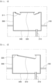
- FIG. 1 is a front view illustrating the liquefied gas storage tank 1 of the present invention
- FIG. 2 is a front view illustrating a state in which the liquefied gas storage tank 1 of the present invention is inclined.
- the plurality of inlet pipes 210 may be provided, and may be formed to pass through the lower wall portion 340 of the inner box unit 300.
- FIG. 3 is a front view illustrating an embodiment in which the supply pipe part 220 is connected to an upper side of the tank unit 100 in the liquefied gas storage tank 1 of the present invention
- FIG. 4 is a front view illustrating a state in which the liquefied gas storage tank 1 of the present invention is inclined in the embodiment in which the supply pipe part 220 of the liquefied gas storage tank 1 of the present invention is connected to the upper side of the tank unit 100.
- one inlet pipe 210 is provided, and is formed to pass through the lower wall portion 340 of the inner box unit 300, and the supply pipe part 220 for transmitting the liquefied gas L to the liquefied gas storage tank 1 may be formed to extend from the upper side.
- FIG. 5 is a front view illustrating a portion of the inner box unit 300 in the liquefied gas storage tank 1 of the present invention
- FIG. 6 is a front view illustrating an embodiment in which one first flip door 311 is provided on the upper wall portion 320 of the inner box unit 300 in the liquefied gas storage tank 1 of the present invention.
- the liquefied gas storage tank 1 may include the tank unit 100 in which the liquefied gas L is stored, the inner box unit 300 that is disposed inside the tank unit 100 and installed at a bottom portion of the tank unit 100, and the pump unit 200 that has the inlet pipe 210 formed to pass through the lower wall portion 340 of the inner box unit 300 and to communicate with the inside of the inner box unit 300, and suctions the liquefied gas L stored in the tank unit through the inlet pipe 210 and supplies the liquefied gas to the outside.
- the inlet pipe 210 of the pump unit 200 is formed to pass through the lower wall portion 340 of the inner box unit 300 and communicate with the inside of the inner box unit 300, so the inlet pipe 210 may be configured to not be exposed to a high-temperature space by being out of the low-temperature liquefied gas L.
- the low-temperature liquefied gas L is pooled in the lower wall portion 340 by gravity.
- the inlet pipe 210 by connecting the inlet pipe 210 to the lower wall portion 340 where the low-temperature liquefied gas L is located, it is possible to prevent the inlet pipe 210 from being exposed to the high-temperature space.
- the inlet pipe 210 may be coupled to the lower wall portion 340 of the inner box unit 300, and may be provided at the same height as the lower wall portion 340. Alternatively, the inlet pipe 210 may be formed to extend into the inner box unit 300 at a predetermined height.
- the inner box unit 300 of the liquefied gas storage tank 1 according to the invention is formed to be depressed downwardly from the bottom portion of the tank unit 100.
- the liquefied gas L received in the tank unit 100 may converge to the lower wall portion 340 of the inner box unit 300 located at the lowest height.
- the inner box unit 300 of the liquefied gas storage tank 1 is provided to surround a periphery of the inlet pipe 210.
- the inner box unit 300 of the liquefied gas storage tank may include a backflow prevention unit 310 provided so that the liquefied gas L is introduced but not discharged.
- the liquefied gas storage tank 1 of the present invention is provided to surround the periphery of the inlet pipe 210 of the pump unit 200, and has the liquefied gas L accommodated therein in one-way, so, as the liquefied gas L fuel is used inside the tank unit 100, a water level of the liquefied gas L fuel is lowered, or as the liquefied gas storage tank 1 is inclined due to sloshing of a ship or the like, the periphery of the inlet pipe 210 may be filled with the liquefied gas L fuel even if the liquefied gas L fuel is biased to one side.
- the tank unit 100 has a configuration that may store cryogenic liquefied gas L, such as liquefied natural gas (LNG) or liquefied petroleum gas (LPG), and may be generally provided by being coupled to a hull 2 of a ship or the like.
- LNG liquefied natural gas
- LPG liquefied petroleum gas
- a heat insulating material may be coupled to an outer surface of the tank unit 100 to ensure the heat insulation of the liquefied gas L.
- the tank unit 100 may include a support member 110 provided therein in order to store internal high-pressure liquefied gas L, and the support member 110 may be provided in a ring shape in the circumferential direction of the tank unit 100.
- the support member 110 may be provided in the form of a disk having a hole in the middle.
- the pump unit 200 serves to transmit the liquefied gas L fuel inside the tank unit 100 to the outside.
- the inlet pipe 210 of the pump unit 200 needs to be immersed in the liquefied gas L.
- the inlet pipe 210 is not immersed in the liquefied gas L fuel, and thus, is exposed to a gas space of the liquefied gas storage tank 1 according to the present invention, by providing the inner box unit 300, it is possible to improve this problem.
- the liquefied gas L is located in the lower wall portion 340 by gravity, and the inlet pipe 210 may be provided on the lower wall portion 340 to be more easily immersed in the liquefied gas L.
- the pump unit 200 may also include the supply pipe part 220 for supplying the liquefied gas L into the tank unit 100 from the outside.
- the supply pipe part 220 may be connected to an upper portion of the tank unit 100, or may be connected to a lower portion of the tank unit 100 in the same manner as the inlet pipe 210.
- the inner box unit 300 serves to fill the periphery of the inlet pipe 210 with the liquefied gas L fuel.
- the inner box unit 300 is provided in the form of a container surrounding the periphery of the inlet pipe 210, and includes the backflow prevention unit 310 through which the liquefied gas L is introduced but not discharged.
- the backflow prevention unit 310 there may be a flip-type first flip door 311 that is opened only in one-way.
- the backflow prevention unit 310 of the liquefied gas storage tank 1 is provided in the inner box unit 300, but may include the first flip door 311 that is provided to be opened and closed only in one direction.
- the first flip door 311 closes an opened area of the inner box unit 300, but may be configured to move the liquefied gas L to be opened in an inflow direction.
- one end portion of the first flip door 311 may be hinged to one side of an opening of the inner box unit 300 and the other end portion thereof may be provided to extend so as to be caught on an inner surface of the inner box unit 300, and the first flip door 311 may move in close contact with the inner box unit 300 due to elasticity.
- the first flip door 311 moves to close the opened area of the inner box unit 300, and is no longer actuated to be opened by pivoting outward, whereas, when the first flip door 311 is pushed to the inside of the inner box unit 300 in order to move the liquefied gas L from the outside of the inner box unit 300 to the inside, the first flip door 311 is actuated to be opened by pivoting.
- one end portion of the first flip door 311, which is hinged to the inner box unit 300, may be provided with a spring member or the like whose elastic force is applied to the outside.
- At least one first flip door 311 of the liquefied gas storage tank 1 may be provided on the upper wall portion 320 or the side wall portion 330 of the inner box unit 300.
- the opening through which the liquefied gas L is introduced into the inner box unit 300 may be formed not only in the upper wall portion 320 of the inner box unit 300 but also in the side wall portion 330 of the inner box unit 300, and the number of openings may be singular or plural.
- the first flip door 311 may be installed in the opening formed in at least one of the upper wall portion 320 and the side wall portion 330 so that the liquefied gas L is accommodated only in the inner box unit 300.
- the inner box unit 300 is configured to close the periphery of the inlet pipe 210 in the state in which the first flip door 311 is closed.
- the liquefied gas L inside the inner box unit 300 is vaporized due to a rise in temperature, etc.
- the liquefied gas is vaporized in the closed area, and thus, may not be vaporized more than a certain amount. Accordingly, it is possible to improve the vaporization problem of the liquefied gas L.
- the inner box unit 300 of the liquefied gas storage tank 1 may share at least one side wall portion 330 with the support member provided in the tank unit 100.
- the inner box unit 300 is provided integrally with the support member coupled to the tank unit 100, it is possible to further increase a coupling force of the inner box unit 300.
- the inner box unit 300 of the liquefied gas storage tank 1 may be provided so that the side wall portion 330 coupled between the support members extends upwardly from the upper wall portion 320.
- the remaining side wall portion 330 further provided in addition to the side wall portion 330 replaced with the support member may be configured to include an extension further extending upwardly from the upper wall portion 320.
- the periphery of the inner box unit 300 serves as a breakwater member so as to not be affected by the flow of the liquefied gas L.
- FIG. 7 is a front view illustrating an embodiment in which a difference pressure pipe 314 is provided in the inner box unit 300 of the liquefied gas storage tank 1 of the present invention.
- the backflow prevention unit 310 of the liquefied gas storage tank 1 may include a differential pressure inlet end portion 314a extending to the outside of the inner box unit 300 and the difference pressure pipe 314 that extends into the inner box unit 300 and is provided with a differential pressure outlet end portion 314b disposed at a lower height than the differential pressure inlet end portion 314a.
- the backflow prevention unit 310 is provided with the difference pressure pipe 314, so the liquefied gas L may be introduced into the inner box unit 300 and is not discharged.
- the inner box unit 300 is provided to surround the periphery of the inlet pipe 210 and accommodates the liquefied gas L therein in one-way, even if the liquefied gas L fuel is biased to one side due to the inclination of the tank unit 100, the periphery of the inlet pipe 210 may be filled with the liquefied gas L fuel.
- the difference pressure pipe 314 may move the liquefied gas L to the inner box unit 300 by the pressure difference due to the differential pressure outlet end portion 314b disposed inside the inner box unit 300 being lower than the differential pressure inlet end portion 314a disposed outside the inner box unit 300.
- a height of a central portion of the difference pressure pipe 314 is not considered and only the height of both end portions of the difference pressure pipe 314 determines the flow direction of the liquefied gas L. Since the differential pressure inlet end portion 314a is higher than the differential pressure outlet end portion 314b, the liquefied gas L flows from the differential pressure inlet end portion 314a to the differential pressure outlet end portion 314b.
- the backflow prevention unit 310 of the liquefied gas storage tank 1 may include an extended inlet end portion that is disposed to face the outside of the inner box unit 300 and provided with the first flip door 311 and an extended pipe that is provided with an extension outlet end portion extending into the inner box unit 300.
- the extended pipe may be configured to make the liquefied gas L flow into the inner box unit 300, but prevent the liquefied gas L from escaping to the outside thereof.
- the extended pipe extends into the inner box unit 300, it is possible to increase the number of paths along which the liquefied gas L accommodated in the inner box unit 300 moves from the extension outlet end portion to the extended inlet end portion. Accordingly, it is possible to more effectively prevent the problem in which the liquefied gas L inside the inner box unit 300 escapes to the outside through the first flip door 311.
- the extended pipe of the liquefied gas storage tank 1 may be formed in the form of a curved pipe in which the extended pipe is disposed in a central portion to be lower than the extended inlet end portion, and is disposed higher than the extension outlet end portion.
- the backflow prevention unit 310 of the liquefied gas storage tank 1 may include an inclined pipe that is disposed on the side wall portion 330 of the inner box unit 300 and provided in the form of a fallopian tube communicating with the outside and has the first flip door 311 provided at the inner end portion thereof.
- the inclined pipe since the inclined pipe has the first flip door 311 provided at the extended inlet end portion thereof, the inclined pipe may be configured to make the liquefied gas L flow into the inner box unit 300, but prevent the liquefied gas L from escaping to the outside thereof.
- FIG. 8 is a front view illustrating an embodiment in which the cryogenic unit 400 is provided in the liquefied gas storage tank 1 of the present invention
- FIG. 9 is a front view illustrating an embodiment in which the cryogenic unit 400 extends to the lower wall portion 340 in the liquefied gas storage tank 1 of the present invention
- FIG. 10 is a front view illustrating an embodiment in which the cryogenic unit 400 extends to the lower wall portion 340 and the side wall portion 330 in the liquefied gas storage tank 1 of the present invention.
- the cryogenic unit 400 may be provided to be in contact with at least the inlet pipe 210 of the liquefied gas storage tank 1 according to the embodiment of the present invention, and to have the liquefied gas L contained therein.
- the liquefied gas storage tank 1 of the present invention may maintain the inlet pipe 210 at a low temperature by including the cryogenic unit 400, so it is possible to prevent the problem in which the liquefied gas L moving through the inlet pipe 210 is vaporized due to the rise in temperature.
- the inlet pipe 210 may be filled with the liquefied gas L by the inner box unit 300, when the liquefied gas L accommodated in the inner box unit 300 is discharged to the outside through the inlet pipe 210, a relatively high-temperature gas region may also be formed around the inlet pipe 210. In this case, since there may be the problem in which the liquefied gas L moving through the inlet pipe 210 is vaporized, the cryogenic unit 400 is provided.
- the cryogenic unit 400 of the liquefied gas storage tank 1 may include an insertion cylinder part 410 that is provided with the inlet pipe 210 to pass therethrough so that the inside of the inner box unit 300 communicates with the inlet pipe 210 and is formed in a cylinder shape in contact with the inlet pipe 210.
- the cryogenic unit 400 includes the insertion cylinder part 410 that is in contact with the periphery of the inlet pipe 210 but has a relatively low-temperature liquefied gas L accommodated therein.
- the liquefied gas L may be liquefied natural gas (LNG), liquefied propane gas (LPG), or the like. Since, for the liquefied natural gas, a boiling point is about -162°C, and for the liquefied propane gas, a boiling point is about -50°C, the temperature of the inlet pipe 210 may be maintained at about -162°C and about -50°C, respectively.
- LNG liquefied natural gas
- LPG liquefied propane gas
- the insertion cylinder part 410 may include an inner pipe part 411 and an exterior part 412.
- the insertion cylinder part 410 of the liquefied gas storage tank 1 may include the inner pipe part 411 that is in contact with the inlet pipe 210 and the exterior part 412 that is spaced apart from the inner pipe part 411 at a predetermined interval to accommodate the liquefied gas L, and has a lower end portion coupled to the inner pipe part 411.
- the inlet pipe 210 may be inserted into and in contact with the inner pipe part 411, and a space may be formed between the inner pipe part 411 and the outer part 412 to accommodate the liquefied gas L.
- the inner pipe part 411 and the exterior part 412 have a double pipe structure, and the lower end portions thereof are coupled to each other to have a structure that may accommodate the liquefied gas L without escaping.
- the insertion cylinder part 410 of the liquefied gas storage tank 1 may be the form in that the upper end portion is opened.
- the first flip door 311 for moving the liquefied gas L only in one-way is provided on the upper end portion of the insertion cylinder, the first flip door 311 may be provided.
- the cryogenic unit 400 of the liquefied gas storage tank 1 may include a double wall portion 420 provided with a second flip door 421 that communicates with the lower end portion of the insertion cylinder part 410, extends to the lower wall portion 340 of the inner box unit 300 or the lower wall portion 340 and the side wall portion 330 of the inner box unit 300, and is opened and closed only in one direction so that the liquefied gas L is introduced into the second flip door 421.
- the double wall portion 420 has an effect of forming the outer portion of the inner box unit 300 in the low-temperature environment.
- the double wall portion 420 may be provided in the lower wall portion 340 of the inner box unit 300, and may be formed in an "L" shape when viewed from a front cross-sectional view. For this, reference may be made to FIG. 9 .
- the liquefied gas L in addition to being able to dispose the liquefied gas L in order to maintain the inlet pipe 210 in the low-temperature environment by the insertion cylinder part 410, in order to maintain the lower wall portion 340 of the inner box unit 300 in the low-temperature environment, the liquefied gas L may be disposed.
- the double wall portion 420 may be provided in the lower wall portion 340 and the side wall portion 330 of the inner box unit 300, and may be formed in a "U" shape when viewed from a front cross-sectional view. For this, reference may be made to FIG. 10 .
- the liquefied gas L in addition to being able to dispose the liquefied gas L in order to maintain the inlet pipe 210 in the low-temperature environment by the insertion cylinder part 410, in order to maintain the lower wall portion 340 and the side wall portion 330 of the inner box unit 300 in the low-temperature environment, the liquefied gas L may be disposed.
- the double wall portion 420 may be a double plate having a space formed therein, and may communicate with the space between the exterior part 412 of the insertion cylinder part 410 and the inner pipe part 411.
- the second flip door 421 is provided on the upper surface portion, and may be configured to accommodate the liquefied gas L into the double wall portion 420, but prevent the liquefied gas L from moving to the outside.
- FIG. 11 is a side view illustrating the liquefied gas storage tank 1 of the present invention and the ship having the same.
- a ship according to another embodiment of the present invention may include a hull 2 that includes the liquefied gas storage tank 1 and an engine unit 2a provided with the liquefied gas storage tank 1 and providing driving force.
- the water level of the liquefied gas L fuel is lowered as the liquefied gas L fuel is used in the tank unit 100, or even if the liquefied gas L fuel is biased to one side due to the inclination of the liquefied gas storage tank 1 due to the sloshing of the vessel, it is possible to fill the periphery of the inlet pipe 210 with the liquefied gas L fuel.
Landscapes
- Engineering & Computer Science (AREA)
- Mechanical Engineering (AREA)
- Chemical & Material Sciences (AREA)
- Combustion & Propulsion (AREA)
- Ocean & Marine Engineering (AREA)
- General Engineering & Computer Science (AREA)
- Filling Or Discharging Of Gas Storage Vessels (AREA)
Claims (12)
- Flüssiggasspeichertank (1), umfassend:
eine Tankeinheit (100), in der Flüssiggas gespeichert ist; eine innere Kasteneinheit (300), die im Inneren der Tankeinheit (100) angeordnet und an einem Bodenabschnitt der Tankeinheit installiert ist; und eine Pumpeneinheit (200), die ein Einlassrohrteil (210) aufweist, das derart ausgebildet ist, dass es durch einen unteren Wandabschnitt der inneren Kasteneinheit (300) verläuft und mit dem Inneren der inneren Kasteneinheit in Verbindung steht, und das Flüssiggas, das in der Tankeinheit (100) gespeichert ist, durch das Einlassrohrteil (210) ansaugt und das Flüssiggas nach außen führt, wobei die innere Kasteneinheit (300) derart ausgebildet ist, dass sie von dem Bodenabschnitt der Tankeinheit nach unten gedrückt wird, und der untere Wandabschnitt der inneren Kasteneinheit (300) auf einer niedrigeren Höhe als der Bodenabschnitt der Tankeinheit ausgebildet ist, wobei die innere Kasteneinheit (300) in Form eines Behälters bereitgestellt ist, der den Umfang des Einlassrohrs (210) umgibt. - Flüssiggasspeichertank (1) nach Anspruch 1, wobei die innere Kasteneinheit (300) eine Rückflussverhinderungseinheit beinhaltet, die bereitgestellt ist, so dass das Flüssiggas eingeleitet, aber nicht abgelassen wird.
- Flüssiggasspeichertank (1) nach Anspruch 2, wobei die Rückflussverhinderungseinheit eine erste Klapptür beinhaltet, die in der inneren Kasteneinheit (300) bereitgestellt ist, die nur in eine Richtung geöffnet und geschlossen wird.
- Flüssiggasspeichertank (1) nach Anspruch 3, wobei mindestens eine erste Klapptür an einem oberen Wandabschnitt oder einem Seitenwandabschnitt der inneren Kasteneinheit bereitgestellt ist.
- Flüssiggasspeichertank (1) nach Anspruch 3, wobei ein Endabschnitt der ersten Klapptür an einer Seite einer Öffnung der inneren Kasteneinheit angelenkt ist und der andere Endabschnitt davon bereitgestellt ist, um sich zu erstrecken, um an einer Innenfläche der inneren Kasteneinheit hängen zu bleiben, und sich die erste Klapptür durch Elastizität in engem Kontakt mit der inneren Kasteneinheit (300) bewegt.
- Flüssiggasspeichertank (1) nach Anspruch 2, wobei die Rückflussverhinderungseinheit ein Differenzdruckrohr beinhaltet, das einen Differenzdruckeinlassendabschnitt, der sich nach außen von der inneren Kasteneinheit (300) erstreckt, und einen Differenzdruckauslassendabschnitt, der sich in die innere Kasteneinheit (300) erstreckt und in einer Höhe angeordnet ist, die niedriger als der Differenzdruckeinlassendabschnitt ist, aufweist.
- Flüssiggasspeichertank (1) nach Anspruch 1, ferner umfassend: eine kryogene Einheit, die bereitgestellt ist, um in Kontakt mit mindestens dem Einlassrohr (210) zu stehen, und das darin enthaltene Flüssiggas aufweist.
- Flüssiggasspeichertank (1) nach Anspruch 7, wobei die kryogene Einheit ein Einsetzzylinderteil beinhaltet, das bereitgestellt ist, um durch das Einlassrohr (210) zu verlaufen, so dass das Innere der inneren Kasteneinheit (300) mit dem Einlassrohr (210) in Verbindung steht, und in einer zylindrischen Form in Kontakt mit dem Einlassrohr (210) ausgebildet ist.
- Flüssiggasspeichertank (1) nach Anspruch 8, wobei das Einsetzzylinderteil Folgendes beinhaltet: ein Innenrohrteil, das mit dem Einlassrohr (210) in Kontakt steht; und ein Außenteil, das von dem Innenrohrteil in einem vorbestimmten Intervall beabstandet ist, um das Flüssiggas aufzunehmen, und einen unteren Endabschnitt aufweist, der an das Innenrohrteil gekoppelt ist.
- Flüssiggasspeichertank (1) nach Anspruch 8, wobei das Einsetzzylinderteil einen geöffneten oberen Endabschnitt aufweist.
- Flüssiggasspeichertank (1) nach Anspruch 8, wobei die kryogene Einheit einen Doppelwandabschnitt beinhaltet, der mit einer zweiten Klapptür bereitgestellt ist, die mit einem unteren Endabschnitt des Einsetzzylinders in Verbindung steht, sich zu einem unteren Wandabschnitt der inneren Kasteneinheit (300) oder dem unteren Wandabschnitt und einem Seitenwandabschnitt der inneren Kasteneinheit erstreckt und nur in eine Richtung geöffnet und geschlossen wird, so dass das Flüssiggas in die zweite Klapptür eingeleitet wird.
- Schiff, umfassend: den Flüssiggasspeichertank (1) nach einem der Ansprüche 1 bis 11; und einen Rumpf, der mit einem Flüssiggasspeichertank (1) bereitgestellt ist und eine Motoreinheit beinhaltet, die Antriebskraft bereitstellt.
Applications Claiming Priority (2)
| Application Number | Priority Date | Filing Date | Title |
|---|---|---|---|
| KR1020190169979A KR102402237B1 (ko) | 2019-12-18 | 2019-12-18 | 액화가스 저장탱크 및 이를 포함하는 선박 |
| PCT/KR2020/017657 WO2021125646A1 (ko) | 2019-12-18 | 2020-12-04 | 액화가스 저장탱크 및 이를 포함하는 선박 |
Publications (4)
| Publication Number | Publication Date |
|---|---|
| EP4079624A1 EP4079624A1 (de) | 2022-10-26 |
| EP4079624A4 EP4079624A4 (de) | 2023-02-01 |
| EP4079624B1 true EP4079624B1 (de) | 2025-06-04 |
| EP4079624C0 EP4079624C0 (de) | 2025-06-04 |
Family
ID=76478453
Family Applications (1)
| Application Number | Title | Priority Date | Filing Date |
|---|---|---|---|
| EP20901956.1A Active EP4079624B1 (de) | 2019-12-18 | 2020-12-04 | Flüssiggastank und schiff damit |
Country Status (5)
| Country | Link |
|---|---|
| US (1) | US12392452B2 (de) |
| EP (1) | EP4079624B1 (de) |
| KR (1) | KR102402237B1 (de) |
| CN (1) | CN114829246B (de) |
| WO (1) | WO2021125646A1 (de) |
Families Citing this family (2)
| Publication number | Priority date | Publication date | Assignee | Title |
|---|---|---|---|---|
| DE102023112617B4 (de) * | 2023-05-12 | 2024-12-05 | Arianegroup Gmbh | Treibstofftank für Flüssigtreibstoff und Verfahren zum Betrieb dieses Treibstofftanks |
| KR102904235B1 (ko) * | 2024-07-12 | 2025-12-24 | 조성갑 | 액화 가스 이송 시스템 |
Citations (1)
| Publication number | Priority date | Publication date | Assignee | Title |
|---|---|---|---|---|
| DE102020007617A1 (de) * | 2020-01-23 | 2021-07-29 | Linde Gmbh | Behälter für ein tiefkaltes Flüssiggas |
Family Cites Families (21)
| Publication number | Priority date | Publication date | Assignee | Title |
|---|---|---|---|---|
| EP0715703B1 (de) * | 1993-06-10 | 2000-09-20 | I.C.O.M. S.R.L. | Verbesserungen an propanflüssiggasbehältern insbesondere an zylindrischen fahrzeugbehältern |
| DE9313562U1 (de) * | 1993-09-08 | 1993-11-25 | Noell-LGA Gastechnik GmbH, 53424 Remagen | Pumpensumpf in Flüssiggasbehältern |
| KR0129287Y1 (ko) * | 1994-12-30 | 1998-12-15 | 전성원 | 차량용 연료펌프의 안전장치 |
| US6234197B1 (en) | 1996-09-23 | 2001-05-22 | Sealand Technology, Inc. | Holding tank vacuum relief |
| KR200221355Y1 (ko) * | 1997-12-31 | 2001-06-01 | 이계안 | 자동차용 연료 탱크 |
| NO20011524L (no) * | 2001-03-23 | 2002-09-24 | Leif Hoeegh & Co Asa | Fartöy og lossesystem |
| FR2876981B1 (fr) * | 2004-10-27 | 2006-12-15 | Gaz Transp Et Technigaz Soc Pa | Dispositif pour l'alimentation en combustible d'une installation de production d'energie d'un navire |
| KR100650606B1 (ko) * | 2005-06-29 | 2006-11-29 | 삼성중공업 주식회사 | 액화 가스를 저장하는 선박용 카고 탱크 |
| JP2008150975A (ja) | 2006-12-15 | 2008-07-03 | Honda Motor Co Ltd | 燃料タンクのサブチャンバ構造 |
| KR100852539B1 (ko) | 2007-08-29 | 2008-08-14 | 대우조선해양 주식회사 | 역류 방지 밸브가 구비된 엘엔지 공급보조장치 |
| KR20100133051A (ko) | 2009-06-11 | 2010-12-21 | 대우조선해양 주식회사 | 액화가스 저장탱크의 펌프 배치구조 및 상기 펌프 배치구조를 갖는 해양 구조물 |
| KR20110129558A (ko) * | 2010-05-26 | 2011-12-02 | 대우조선해양 주식회사 | 부유식 구조물의 액화연료가스 공급장치 |
| KR101494118B1 (ko) * | 2011-02-07 | 2015-02-16 | 미츠비시 쥬고교 가부시키가이샤 | 액체 흡입 장치 |
| FI123162B (fi) * | 2011-05-04 | 2012-11-30 | Waertsilae Finland Oy | Nestekaasun poistojärjestelmä, säiliö nestekaasun varastoimiseksi, menetelmä nestekaasusäiliön uusimiseksi ja menetelmä nestekaasusäiliön valmistamiseksi |
| KR20110126575A (ko) * | 2011-10-12 | 2011-11-23 | 대우조선해양 주식회사 | 액화가스 저장탱크의 펌프 배치구조 및 상기 펌프 배치구조를 갖는 해양 구조물 |
| JP5606466B2 (ja) * | 2012-02-07 | 2014-10-15 | 岩谷産業株式会社 | ガス供給装置 |
| KR20140091891A (ko) * | 2013-01-14 | 2014-07-23 | 현대중공업 주식회사 | 펌프 가이드 및 이를 구비한 해상 부유 구조물 |
| CN105042328B (zh) * | 2015-08-26 | 2017-11-10 | 成都华气厚普机电设备股份有限公司 | 内置式无底阀lng泵井结构 |
| JP2017170767A (ja) | 2016-03-24 | 2017-09-28 | セイコーエプソン株式会社 | 記録装置および記録方法 |
| PT3318791T (pt) | 2016-11-07 | 2021-03-02 | Ac Inox Gmbh | Tanque de carga de múltiplos lóbulos |
| JP2019044733A (ja) | 2017-09-06 | 2019-03-22 | 三菱電機株式会社 | 燃料供給装置 |
-
2019
- 2019-12-18 KR KR1020190169979A patent/KR102402237B1/ko active Active
-
2020
- 2020-12-04 EP EP20901956.1A patent/EP4079624B1/de active Active
- 2020-12-04 CN CN202080087343.XA patent/CN114829246B/zh active Active
- 2020-12-04 US US17/786,284 patent/US12392452B2/en active Active
- 2020-12-04 WO PCT/KR2020/017657 patent/WO2021125646A1/ko not_active Ceased
Patent Citations (1)
| Publication number | Priority date | Publication date | Assignee | Title |
|---|---|---|---|---|
| DE102020007617A1 (de) * | 2020-01-23 | 2021-07-29 | Linde Gmbh | Behälter für ein tiefkaltes Flüssiggas |
Also Published As
| Publication number | Publication date |
|---|---|
| KR20210078177A (ko) | 2021-06-28 |
| WO2021125646A1 (ko) | 2021-06-24 |
| US20230027991A1 (en) | 2023-01-26 |
| CN114829246B (zh) | 2025-07-01 |
| EP4079624A1 (de) | 2022-10-26 |
| EP4079624C0 (de) | 2025-06-04 |
| EP4079624A4 (de) | 2023-02-01 |
| US12392452B2 (en) | 2025-08-19 |
| KR102402237B1 (ko) | 2022-05-26 |
| CN114829246A (zh) | 2022-07-29 |
Similar Documents
| Publication | Publication Date | Title |
|---|---|---|
| US10400953B2 (en) | Pump tower of liquefied gas storage tank | |
| JP5727676B2 (ja) | 外側容器を有する海上プラットフォーム | |
| EP4079624B1 (de) | Flüssiggastank und schiff damit | |
| KR20180051637A (ko) | 해양 선박의 연료 탱크 배열체 | |
| KR101983901B1 (ko) | 선박용 액체저장탱크 | |
| KR102727744B1 (ko) | 액화가스 저장탱크 및 이를 포함하는 선박 | |
| KR100964826B1 (ko) | 액화가스 저장탱크의 액화가스 공급용 배관 | |
| KR20160034517A (ko) | 액화가스 저장탱크 및 이를 구비한 해양구조물 | |
| KR20160061096A (ko) | 액체저장탱크 | |
| CN114771740A (zh) | 一种船用液化气体燃料罐及船舶 | |
| KR101984981B1 (ko) | 해양 구조물의 액화가스 저장탱크 | |
| KR102445127B1 (ko) | 액화가스 저장탱크 및 이를 포함하는 선박 | |
| JP2003166697A (ja) | 水素貯蔵タンク | |
| KR102028802B1 (ko) | 액화가스 저장탱크 및 이를 구비하는 선박 | |
| KR20230095479A (ko) | 이중박스구조를 구비한 액화가스 저장탱크 및 이를 포함하는 선박 | |
| CN112320121B (zh) | 船用储罐 | |
| KR20230095480A (ko) | 돌출부를 구비한 액화가스 저장탱크 및 이를 포함하는 선박 | |
| KR102768509B1 (ko) | Lng 저장탱크의 슬로싱 저감 시스템 | |
| KR102905749B1 (ko) | 데크 탱크를 포함하는 선박 | |
| KR101936909B1 (ko) | 해양 구조물의 액화가스 저장탱크 | |
| CN111396737A (zh) | 船用液罐 | |
| KR20240146986A (ko) | 연료 저장 탱크 및 이를 포함하는 선박 | |
| KR101894946B1 (ko) | 해양 구조물의 액화가스 저장탱크 | |
| KR20250059606A (ko) | 이중 단열층과 기화가스를 활용하여 단열성능이 향상된 선박용 액화수소 연료탱크 | |
| KR20250148759A (ko) | 액화가스 저장탱크 |
Legal Events
| Date | Code | Title | Description |
|---|---|---|---|
| STAA | Information on the status of an ep patent application or granted ep patent |
Free format text: STATUS: THE INTERNATIONAL PUBLICATION HAS BEEN MADE |
|
| PUAI | Public reference made under article 153(3) epc to a published international application that has entered the european phase |
Free format text: ORIGINAL CODE: 0009012 |
|
| STAA | Information on the status of an ep patent application or granted ep patent |
Free format text: STATUS: REQUEST FOR EXAMINATION WAS MADE |
|
| 17P | Request for examination filed |
Effective date: 20220707 |
|
| AK | Designated contracting states |
Kind code of ref document: A1 Designated state(s): AL AT BE BG CH CY CZ DE DK EE ES FI FR GB GR HR HU IE IS IT LI LT LU LV MC MK MT NL NO PL PT RO RS SE SI SK SM TR |
|
| A4 | Supplementary search report drawn up and despatched |
Effective date: 20230105 |
|
| RIC1 | Information provided on ipc code assigned before grant |
Ipc: F17C 9/00 20060101ALI20221223BHEP Ipc: B63H 21/38 20060101ALI20221223BHEP Ipc: B63B 27/24 20060101ALI20221223BHEP Ipc: B63B 25/16 20060101AFI20221223BHEP |
|
| DAV | Request for validation of the european patent (deleted) | ||
| DAX | Request for extension of the european patent (deleted) | ||
| GRAP | Despatch of communication of intention to grant a patent |
Free format text: ORIGINAL CODE: EPIDOSNIGR1 |
|
| STAA | Information on the status of an ep patent application or granted ep patent |
Free format text: STATUS: GRANT OF PATENT IS INTENDED |
|
| INTG | Intention to grant announced |
Effective date: 20250103 |
|
| GRAS | Grant fee paid |
Free format text: ORIGINAL CODE: EPIDOSNIGR3 |
|
| GRAA | (expected) grant |
Free format text: ORIGINAL CODE: 0009210 |
|
| STAA | Information on the status of an ep patent application or granted ep patent |
Free format text: STATUS: THE PATENT HAS BEEN GRANTED |
|
| AK | Designated contracting states |
Kind code of ref document: B1 Designated state(s): AL AT BE BG CH CY CZ DE DK EE ES FI FR GB GR HR HU IE IS IT LI LT LU LV MC MK MT NL NO PL PT RO RS SE SI SK SM TR |
|
| REG | Reference to a national code |
Ref country code: GB Ref legal event code: FG4D |
|
| REG | Reference to a national code |
Ref country code: CH Ref legal event code: EP |
|
| REG | Reference to a national code |
Ref country code: DE Ref legal event code: R096 Ref document number: 602020052464 Country of ref document: DE |
|
| REG | Reference to a national code |
Ref country code: IE Ref legal event code: FG4D |
|
| U01 | Request for unitary effect filed |
Effective date: 20250624 |
|
| U07 | Unitary effect registered |
Designated state(s): AT BE BG DE DK EE FI FR IT LT LU LV MT NL PT RO SE SI Effective date: 20250701 |
|
| PG25 | Lapsed in a contracting state [announced via postgrant information from national office to epo] |
Ref country code: ES Free format text: LAPSE BECAUSE OF FAILURE TO SUBMIT A TRANSLATION OF THE DESCRIPTION OR TO PAY THE FEE WITHIN THE PRESCRIBED TIME-LIMIT Effective date: 20250604 |
|
| PG25 | Lapsed in a contracting state [announced via postgrant information from national office to epo] |
Ref country code: NO Free format text: LAPSE BECAUSE OF FAILURE TO SUBMIT A TRANSLATION OF THE DESCRIPTION OR TO PAY THE FEE WITHIN THE PRESCRIBED TIME-LIMIT Effective date: 20250904 Ref country code: GR Free format text: LAPSE BECAUSE OF FAILURE TO SUBMIT A TRANSLATION OF THE DESCRIPTION OR TO PAY THE FEE WITHIN THE PRESCRIBED TIME-LIMIT Effective date: 20250905 |
|
| PG25 | Lapsed in a contracting state [announced via postgrant information from national office to epo] |
Ref country code: PL Free format text: LAPSE BECAUSE OF FAILURE TO SUBMIT A TRANSLATION OF THE DESCRIPTION OR TO PAY THE FEE WITHIN THE PRESCRIBED TIME-LIMIT Effective date: 20250604 |
|
| PG25 | Lapsed in a contracting state [announced via postgrant information from national office to epo] |
Ref country code: HR Free format text: LAPSE BECAUSE OF FAILURE TO SUBMIT A TRANSLATION OF THE DESCRIPTION OR TO PAY THE FEE WITHIN THE PRESCRIBED TIME-LIMIT Effective date: 20250604 |
|
| PG25 | Lapsed in a contracting state [announced via postgrant information from national office to epo] |
Ref country code: RS Free format text: LAPSE BECAUSE OF FAILURE TO SUBMIT A TRANSLATION OF THE DESCRIPTION OR TO PAY THE FEE WITHIN THE PRESCRIBED TIME-LIMIT Effective date: 20250904 |
|
| PG25 | Lapsed in a contracting state [announced via postgrant information from national office to epo] |
Ref country code: IS Free format text: LAPSE BECAUSE OF FAILURE TO SUBMIT A TRANSLATION OF THE DESCRIPTION OR TO PAY THE FEE WITHIN THE PRESCRIBED TIME-LIMIT Effective date: 20251004 |
|
| PG25 | Lapsed in a contracting state [announced via postgrant information from national office to epo] |
Ref country code: SM Free format text: LAPSE BECAUSE OF FAILURE TO SUBMIT A TRANSLATION OF THE DESCRIPTION OR TO PAY THE FEE WITHIN THE PRESCRIBED TIME-LIMIT Effective date: 20250604 |
|
| PG25 | Lapsed in a contracting state [announced via postgrant information from national office to epo] |
Ref country code: CZ Free format text: LAPSE BECAUSE OF FAILURE TO SUBMIT A TRANSLATION OF THE DESCRIPTION OR TO PAY THE FEE WITHIN THE PRESCRIBED TIME-LIMIT Effective date: 20250604 |
|
| PG25 | Lapsed in a contracting state [announced via postgrant information from national office to epo] |
Ref country code: SK Free format text: LAPSE BECAUSE OF FAILURE TO SUBMIT A TRANSLATION OF THE DESCRIPTION OR TO PAY THE FEE WITHIN THE PRESCRIBED TIME-LIMIT Effective date: 20250604 |
|
| U20 | Renewal fee for the european patent with unitary effect paid |
Year of fee payment: 6 Effective date: 20251219 |