EP4079564A1 - Appareil de commande pour moteur électrique et véhicule - Google Patents
Appareil de commande pour moteur électrique et véhicule Download PDFInfo
- Publication number
- EP4079564A1 EP4079564A1 EP22167766.9A EP22167766A EP4079564A1 EP 4079564 A1 EP4079564 A1 EP 4079564A1 EP 22167766 A EP22167766 A EP 22167766A EP 4079564 A1 EP4079564 A1 EP 4079564A1
- Authority
- EP
- European Patent Office
- Prior art keywords
- temperature
- rotor
- electric motor
- control apparatus
- estimated
- Prior art date
- Legal status (The legal status is an assumption and is not a legal conclusion. Google has not performed a legal analysis and makes no representation as to the accuracy of the status listed.)
- Granted
Links
- 239000003507 refrigerant Substances 0.000 claims abstract description 24
- 238000005520 cutting process Methods 0.000 claims description 3
- 238000000034 method Methods 0.000 description 35
- 230000000052 comparative effect Effects 0.000 description 19
- 238000001514 detection method Methods 0.000 description 17
- 238000003860 storage Methods 0.000 description 16
- 239000002826 coolant Substances 0.000 description 15
- 230000008859 change Effects 0.000 description 14
- 230000006870 function Effects 0.000 description 10
- 230000007423 decrease Effects 0.000 description 9
- 238000001816 cooling Methods 0.000 description 8
- 238000012886 linear function Methods 0.000 description 7
- 230000015654 memory Effects 0.000 description 7
- 230000005347 demagnetization Effects 0.000 description 6
- 238000005259 measurement Methods 0.000 description 6
- 230000007704 transition Effects 0.000 description 6
- 238000001914 filtration Methods 0.000 description 5
- 238000010586 diagram Methods 0.000 description 4
- 230000007246 mechanism Effects 0.000 description 4
- BASFCYQUMIYNBI-UHFFFAOYSA-N platinum Chemical compound [Pt] BASFCYQUMIYNBI-UHFFFAOYSA-N 0.000 description 4
- XLYOFNOQVPJJNP-UHFFFAOYSA-N water Substances O XLYOFNOQVPJJNP-UHFFFAOYSA-N 0.000 description 4
- 230000003247 decreasing effect Effects 0.000 description 3
- 230000009467 reduction Effects 0.000 description 3
- XEEYBQQBJWHFJM-UHFFFAOYSA-N Iron Chemical compound [Fe] XEEYBQQBJWHFJM-UHFFFAOYSA-N 0.000 description 2
- 229910000831 Steel Inorganic materials 0.000 description 2
- 230000000694 effects Effects 0.000 description 2
- 230000004907 flux Effects 0.000 description 2
- 230000004048 modification Effects 0.000 description 2
- 238000012986 modification Methods 0.000 description 2
- 229910052697 platinum Inorganic materials 0.000 description 2
- 239000011347 resin Substances 0.000 description 2
- 229920005989 resin Polymers 0.000 description 2
- 230000004043 responsiveness Effects 0.000 description 2
- 230000000717 retained effect Effects 0.000 description 2
- 239000004065 semiconductor Substances 0.000 description 2
- 239000010959 steel Substances 0.000 description 2
- HBBGRARXTFLTSG-UHFFFAOYSA-N Lithium ion Chemical compound [Li+] HBBGRARXTFLTSG-UHFFFAOYSA-N 0.000 description 1
- 230000008901 benefit Effects 0.000 description 1
- 238000002485 combustion reaction Methods 0.000 description 1
- 239000004020 conductor Substances 0.000 description 1
- 239000000498 cooling water Substances 0.000 description 1
- 230000005669 field effect Effects 0.000 description 1
- 238000009499 grossing Methods 0.000 description 1
- 229910052739 hydrogen Inorganic materials 0.000 description 1
- 239000001257 hydrogen Substances 0.000 description 1
- 230000006698 induction Effects 0.000 description 1
- 229910052742 iron Inorganic materials 0.000 description 1
- 229910001416 lithium ion Inorganic materials 0.000 description 1
- 230000005389 magnetism Effects 0.000 description 1
- 238000004519 manufacturing process Methods 0.000 description 1
- 230000007935 neutral effect Effects 0.000 description 1
- 230000001172 regenerating effect Effects 0.000 description 1
- 230000000630 rising effect Effects 0.000 description 1
Images


Classifications
-
- B—PERFORMING OPERATIONS; TRANSPORTING
- B60—VEHICLES IN GENERAL
- B60L—PROPULSION OF ELECTRICALLY-PROPELLED VEHICLES; SUPPLYING ELECTRIC POWER FOR AUXILIARY EQUIPMENT OF ELECTRICALLY-PROPELLED VEHICLES; ELECTRODYNAMIC BRAKE SYSTEMS FOR VEHICLES IN GENERAL; MAGNETIC SUSPENSION OR LEVITATION FOR VEHICLES; MONITORING OPERATING VARIABLES OF ELECTRICALLY-PROPELLED VEHICLES; ELECTRIC SAFETY DEVICES FOR ELECTRICALLY-PROPELLED VEHICLES
- B60L15/00—Methods, circuits, or devices for controlling the traction-motor speed of electrically-propelled vehicles
- B60L15/20—Methods, circuits, or devices for controlling the traction-motor speed of electrically-propelled vehicles for control of the vehicle or its driving motor to achieve a desired performance, e.g. speed, torque, programmed variation of speed
- B60L15/2045—Methods, circuits, or devices for controlling the traction-motor speed of electrically-propelled vehicles for control of the vehicle or its driving motor to achieve a desired performance, e.g. speed, torque, programmed variation of speed for optimising the use of energy
-
- B—PERFORMING OPERATIONS; TRANSPORTING
- B60—VEHICLES IN GENERAL
- B60W—CONJOINT CONTROL OF VEHICLE SUB-UNITS OF DIFFERENT TYPE OR DIFFERENT FUNCTION; CONTROL SYSTEMS SPECIALLY ADAPTED FOR HYBRID VEHICLES; ROAD VEHICLE DRIVE CONTROL SYSTEMS FOR PURPOSES NOT RELATED TO THE CONTROL OF A PARTICULAR SUB-UNIT
- B60W40/00—Estimation or calculation of non-directly measurable driving parameters for road vehicle drive control systems not related to the control of a particular sub unit, e.g. by using mathematical models
- B60W40/12—Estimation or calculation of non-directly measurable driving parameters for road vehicle drive control systems not related to the control of a particular sub unit, e.g. by using mathematical models related to parameters of the vehicle itself, e.g. tyre models
-
- B—PERFORMING OPERATIONS; TRANSPORTING
- B60—VEHICLES IN GENERAL
- B60L—PROPULSION OF ELECTRICALLY-PROPELLED VEHICLES; SUPPLYING ELECTRIC POWER FOR AUXILIARY EQUIPMENT OF ELECTRICALLY-PROPELLED VEHICLES; ELECTRODYNAMIC BRAKE SYSTEMS FOR VEHICLES IN GENERAL; MAGNETIC SUSPENSION OR LEVITATION FOR VEHICLES; MONITORING OPERATING VARIABLES OF ELECTRICALLY-PROPELLED VEHICLES; ELECTRIC SAFETY DEVICES FOR ELECTRICALLY-PROPELLED VEHICLES
- B60L3/00—Electric devices on electrically-propelled vehicles for safety purposes; Monitoring operating variables, e.g. speed, deceleration or energy consumption
- B60L3/06—Limiting the traction current under mechanical overload conditions
-
- B—PERFORMING OPERATIONS; TRANSPORTING
- B60—VEHICLES IN GENERAL
- B60L—PROPULSION OF ELECTRICALLY-PROPELLED VEHICLES; SUPPLYING ELECTRIC POWER FOR AUXILIARY EQUIPMENT OF ELECTRICALLY-PROPELLED VEHICLES; ELECTRODYNAMIC BRAKE SYSTEMS FOR VEHICLES IN GENERAL; MAGNETIC SUSPENSION OR LEVITATION FOR VEHICLES; MONITORING OPERATING VARIABLES OF ELECTRICALLY-PROPELLED VEHICLES; ELECTRIC SAFETY DEVICES FOR ELECTRICALLY-PROPELLED VEHICLES
- B60L3/00—Electric devices on electrically-propelled vehicles for safety purposes; Monitoring operating variables, e.g. speed, deceleration or energy consumption
- B60L3/12—Recording operating variables ; Monitoring of operating variables
-
- B—PERFORMING OPERATIONS; TRANSPORTING
- B60—VEHICLES IN GENERAL
- B60W—CONJOINT CONTROL OF VEHICLE SUB-UNITS OF DIFFERENT TYPE OR DIFFERENT FUNCTION; CONTROL SYSTEMS SPECIALLY ADAPTED FOR HYBRID VEHICLES; ROAD VEHICLE DRIVE CONTROL SYSTEMS FOR PURPOSES NOT RELATED TO THE CONTROL OF A PARTICULAR SUB-UNIT
- B60W30/00—Purposes of road vehicle drive control systems not related to the control of a particular sub-unit, e.g. of systems using conjoint control of vehicle sub-units
- B60W30/18—Propelling the vehicle
- B60W30/18009—Propelling the vehicle related to particular drive situations
- B60W30/18018—Start-stop drive, e.g. in a traffic jam
-
- B—PERFORMING OPERATIONS; TRANSPORTING
- B60—VEHICLES IN GENERAL
- B60W—CONJOINT CONTROL OF VEHICLE SUB-UNITS OF DIFFERENT TYPE OR DIFFERENT FUNCTION; CONTROL SYSTEMS SPECIALLY ADAPTED FOR HYBRID VEHICLES; ROAD VEHICLE DRIVE CONTROL SYSTEMS FOR PURPOSES NOT RELATED TO THE CONTROL OF A PARTICULAR SUB-UNIT
- B60W40/00—Estimation or calculation of non-directly measurable driving parameters for road vehicle drive control systems not related to the control of a particular sub unit, e.g. by using mathematical models
- B60W40/10—Estimation or calculation of non-directly measurable driving parameters for road vehicle drive control systems not related to the control of a particular sub unit, e.g. by using mathematical models related to vehicle motion
- B60W40/105—Speed
-
- G—PHYSICS
- G01—MEASURING; TESTING
- G01K—MEASURING TEMPERATURE; MEASURING QUANTITY OF HEAT; THERMALLY-SENSITIVE ELEMENTS NOT OTHERWISE PROVIDED FOR
- G01K13/00—Thermometers specially adapted for specific purposes
- G01K13/04—Thermometers specially adapted for specific purposes for measuring temperature of moving solid bodies
- G01K13/08—Thermometers specially adapted for specific purposes for measuring temperature of moving solid bodies in rotary movement
-
- G—PHYSICS
- G01—MEASURING; TESTING
- G01K—MEASURING TEMPERATURE; MEASURING QUANTITY OF HEAT; THERMALLY-SENSITIVE ELEMENTS NOT OTHERWISE PROVIDED FOR
- G01K7/00—Measuring temperature based on the use of electric or magnetic elements directly sensitive to heat ; Power supply therefor, e.g. using thermoelectric elements
- G01K7/42—Circuits effecting compensation of thermal inertia; Circuits for predicting the stationary value of a temperature
- G01K7/427—Temperature calculation based on spatial modeling, e.g. spatial inter- or extrapolation
-
- H—ELECTRICITY
- H02—GENERATION; CONVERSION OR DISTRIBUTION OF ELECTRIC POWER
- H02P—CONTROL OR REGULATION OF ELECTRIC MOTORS, ELECTRIC GENERATORS OR DYNAMO-ELECTRIC CONVERTERS; CONTROLLING TRANSFORMERS, REACTORS OR CHOKE COILS
- H02P29/00—Arrangements for regulating or controlling electric motors, appropriate for both AC and DC motors
- H02P29/60—Controlling or determining the temperature of the motor or of the drive
- H02P29/66—Controlling or determining the temperature of the rotor
- H02P29/662—Controlling or determining the temperature of the rotor the rotor having permanent magnets
-
- B—PERFORMING OPERATIONS; TRANSPORTING
- B60—VEHICLES IN GENERAL
- B60L—PROPULSION OF ELECTRICALLY-PROPELLED VEHICLES; SUPPLYING ELECTRIC POWER FOR AUXILIARY EQUIPMENT OF ELECTRICALLY-PROPELLED VEHICLES; ELECTRODYNAMIC BRAKE SYSTEMS FOR VEHICLES IN GENERAL; MAGNETIC SUSPENSION OR LEVITATION FOR VEHICLES; MONITORING OPERATING VARIABLES OF ELECTRICALLY-PROPELLED VEHICLES; ELECTRIC SAFETY DEVICES FOR ELECTRICALLY-PROPELLED VEHICLES
- B60L2220/00—Electrical machine types; Structures or applications thereof
- B60L2220/10—Electrical machine types
- B60L2220/18—Reluctance machines
-
- B—PERFORMING OPERATIONS; TRANSPORTING
- B60—VEHICLES IN GENERAL
- B60L—PROPULSION OF ELECTRICALLY-PROPELLED VEHICLES; SUPPLYING ELECTRIC POWER FOR AUXILIARY EQUIPMENT OF ELECTRICALLY-PROPELLED VEHICLES; ELECTRODYNAMIC BRAKE SYSTEMS FOR VEHICLES IN GENERAL; MAGNETIC SUSPENSION OR LEVITATION FOR VEHICLES; MONITORING OPERATING VARIABLES OF ELECTRICALLY-PROPELLED VEHICLES; ELECTRIC SAFETY DEVICES FOR ELECTRICALLY-PROPELLED VEHICLES
- B60L2240/00—Control parameters of input or output; Target parameters
- B60L2240/40—Drive Train control parameters
- B60L2240/42—Drive Train control parameters related to electric machines
- B60L2240/421—Speed
-
- B—PERFORMING OPERATIONS; TRANSPORTING
- B60—VEHICLES IN GENERAL
- B60L—PROPULSION OF ELECTRICALLY-PROPELLED VEHICLES; SUPPLYING ELECTRIC POWER FOR AUXILIARY EQUIPMENT OF ELECTRICALLY-PROPELLED VEHICLES; ELECTRODYNAMIC BRAKE SYSTEMS FOR VEHICLES IN GENERAL; MAGNETIC SUSPENSION OR LEVITATION FOR VEHICLES; MONITORING OPERATING VARIABLES OF ELECTRICALLY-PROPELLED VEHICLES; ELECTRIC SAFETY DEVICES FOR ELECTRICALLY-PROPELLED VEHICLES
- B60L2240/00—Control parameters of input or output; Target parameters
- B60L2240/40—Drive Train control parameters
- B60L2240/42—Drive Train control parameters related to electric machines
- B60L2240/423—Torque
-
- B—PERFORMING OPERATIONS; TRANSPORTING
- B60—VEHICLES IN GENERAL
- B60L—PROPULSION OF ELECTRICALLY-PROPELLED VEHICLES; SUPPLYING ELECTRIC POWER FOR AUXILIARY EQUIPMENT OF ELECTRICALLY-PROPELLED VEHICLES; ELECTRODYNAMIC BRAKE SYSTEMS FOR VEHICLES IN GENERAL; MAGNETIC SUSPENSION OR LEVITATION FOR VEHICLES; MONITORING OPERATING VARIABLES OF ELECTRICALLY-PROPELLED VEHICLES; ELECTRIC SAFETY DEVICES FOR ELECTRICALLY-PROPELLED VEHICLES
- B60L2240/00—Control parameters of input or output; Target parameters
- B60L2240/40—Drive Train control parameters
- B60L2240/42—Drive Train control parameters related to electric machines
- B60L2240/425—Temperature
-
- B—PERFORMING OPERATIONS; TRANSPORTING
- B60—VEHICLES IN GENERAL
- B60L—PROPULSION OF ELECTRICALLY-PROPELLED VEHICLES; SUPPLYING ELECTRIC POWER FOR AUXILIARY EQUIPMENT OF ELECTRICALLY-PROPELLED VEHICLES; ELECTRODYNAMIC BRAKE SYSTEMS FOR VEHICLES IN GENERAL; MAGNETIC SUSPENSION OR LEVITATION FOR VEHICLES; MONITORING OPERATING VARIABLES OF ELECTRICALLY-PROPELLED VEHICLES; ELECTRIC SAFETY DEVICES FOR ELECTRICALLY-PROPELLED VEHICLES
- B60L2260/00—Operating Modes
- B60L2260/20—Drive modes; Transition between modes
- B60L2260/26—Transition between different drive modes
-
- B—PERFORMING OPERATIONS; TRANSPORTING
- B60—VEHICLES IN GENERAL
- B60L—PROPULSION OF ELECTRICALLY-PROPELLED VEHICLES; SUPPLYING ELECTRIC POWER FOR AUXILIARY EQUIPMENT OF ELECTRICALLY-PROPELLED VEHICLES; ELECTRODYNAMIC BRAKE SYSTEMS FOR VEHICLES IN GENERAL; MAGNETIC SUSPENSION OR LEVITATION FOR VEHICLES; MONITORING OPERATING VARIABLES OF ELECTRICALLY-PROPELLED VEHICLES; ELECTRIC SAFETY DEVICES FOR ELECTRICALLY-PROPELLED VEHICLES
- B60L2260/00—Operating Modes
- B60L2260/40—Control modes
- B60L2260/44—Control modes by parameter estimation
-
- B—PERFORMING OPERATIONS; TRANSPORTING
- B60—VEHICLES IN GENERAL
- B60W—CONJOINT CONTROL OF VEHICLE SUB-UNITS OF DIFFERENT TYPE OR DIFFERENT FUNCTION; CONTROL SYSTEMS SPECIALLY ADAPTED FOR HYBRID VEHICLES; ROAD VEHICLE DRIVE CONTROL SYSTEMS FOR PURPOSES NOT RELATED TO THE CONTROL OF A PARTICULAR SUB-UNIT
- B60W2510/00—Input parameters relating to a particular sub-units
- B60W2510/08—Electric propulsion units
- B60W2510/087—Temperature
-
- Y—GENERAL TAGGING OF NEW TECHNOLOGICAL DEVELOPMENTS; GENERAL TAGGING OF CROSS-SECTIONAL TECHNOLOGIES SPANNING OVER SEVERAL SECTIONS OF THE IPC; TECHNICAL SUBJECTS COVERED BY FORMER USPC CROSS-REFERENCE ART COLLECTIONS [XRACs] AND DIGESTS
- Y02—TECHNOLOGIES OR APPLICATIONS FOR MITIGATION OR ADAPTATION AGAINST CLIMATE CHANGE
- Y02T—CLIMATE CHANGE MITIGATION TECHNOLOGIES RELATED TO TRANSPORTATION
- Y02T10/00—Road transport of goods or passengers
- Y02T10/60—Other road transportation technologies with climate change mitigation effect
- Y02T10/64—Electric machine technologies in electromobility
Definitions
- the present disclosure relates to a control apparatus that controls an electric motor mounted on a vehicle.
- the present disclosure also relates to a vehicle provided with such a control apparatus.
- control apparatus for an electric motor for a vehicle
- JP 6026815 B Conventionally, as a control apparatus for an electric motor for a vehicle, there has been a control apparatus described in JP 6026815 B .
- the control apparatus is mounted on a vehicle provided with an electric motor that is cooled by cooling oil.
- the control apparatus is adapted to control output of the electric motor based on the temperature of the coil of a stator and the oil temperature of the cooling oil.
- Permanent magnets that are embedded and fixed to the rotor of an electric motor are irreversibly demagnetized when the temperature is higher than a predetermined temperature, and the performance of the electric motor is reduced. Further, since loss of the electric motor increases when the electric motor is rotating at a high speed, the amount of generated heat of the electric motor becomes large, and the temperature of the rotor easily becomes high. Therefore, it is necessary to control output of the electric motor when the electric motor is rotating at a high speed.
- a control apparatus for controlling an electric motor mounted on a vehicle, the control apparatus including: a rotor temperature estimation unit estimating a temperature of a rotor based on stator temperature information from a stator temperature identification unit for identifying a temperature of a stator, refrigerant temperature information from a refrigerant temperature identification unit for identifying a temperature of refrigerant used to cool the electric motor, and rotation speed information about the rotor from a rotation speed identification unit for identifying a rotation speed of the rotor; and a control unit controlling at least one of an output characteristic and a drive condition of the electric motor based on the temperature of the rotor estimated by the rotor temperature estimation unit.
- the above electric motor may be configured to be capable of generating motive power but not electric power.
- the electric motor may be a so-called motor generator and configured to be capable of generating both of motive power and electric power.
- temperature identification units may, of course, be temperature sensors installed on temperature detection targets, or may include one or more temperature sensors installed on parts other than the temperature detection targets, and a control unit that estimates temperatures of the temperature detection targets based on one or more temperatures detected by the one or more temperature sensors and information such as a map or a program (software) stored in a storage unit.
- the above various kinds of temperature identification units may include one or more sensors other than the temperature sensors installed on the temperature detection targets, for example, one or more sensors among one or more temperature sensors that are not installed on the temperature detection targets, a current sensor, a voltage sensor and a rotation speed detection sensor, and a control unit that estimates the temperatures of the temperature detection targets based on one or more items of physical information detected by the one or more sensors, and the information such as the map or the program stored in the storage unit.
- the above various kinds of temperature identification units may have any configuration capable of detecting or estimating the temperatures of temperature detection targets.
- the rotation speed identification unit may, of course, be configured with a rotation speed detection sensor that directly detects the rotation speed of the rotor, for example, a rotation speed detection sensor that includes a resolver and a pulsar ring, or the like, or may include one or more sensors other than the rotation speed detection sensor, for example, one or more sensors among a temperature sensor, a current sensor and a voltage sensor, and a control unit that estimates the rotation speed of the rotor based on one or more items of physical information detected by the one or more sensors, and information such as the map or the program stored in the storage unit.
- the above rotation speed identification unit may have any configuration capable of detecting or estimating the rotation speed of the rotor.
- the control apparatus controls at least one of the output characteristic and the drive condition of the electric motor in consideration of the rotation speed of the rotor in addition to the stator temperature information and the refrigerant temperature information. Therefore, it is possible to prevent output from being excessively limited when the electric motor is rotating at a low speed, and it is possible to cause the electric motor to efficiently operate at both the time of rotating at a low speed and the time of rotating at a high speed.
- the rotator may include permanent magnets; and the control unit may control at least one of the output characteristic and the drive condition of the electric motor so that the permanent magnets are not demagnetized, based on the temperature of the rotor.
- an electric power source cutoff time identification unit identifying electric power source cutoff time during which an electric power source for the vehicle is cut off; and a start-up temperature estimation unit estimating a temperature of the rotor at the time of energizing the vehicle for which the electric power source cutoff time has ended, based on the electric power source cutoff time and a temperature of the rotor, estimated by the rotor temperature estimation unit, immediately before cutting off the electric power source.
- the present configuration it is possible to estimate the temperature of the rotor at the time of the vehicle being started up. Therefore, it is possible to cause the electric motor to efficiently operate from when the vehicle is started up, and it is possible to cause the electric motor to output a high torque from when the vehicle is started up. Therefore, it is possible to realize a motive power mechanism that is superior in responsiveness to an operation from when the vehicle is started up.
- a vehicle of the present disclosure includes the control apparatus of the present disclosure.
- a control apparatus for an electric motor of a vehicle it is possible to cause the electric motor to operate efficiently, and in particular, it is possible to increase torque that the electric motor outputs when rotating at a low speed.
- FIG. 1 is a schematic configuration diagram of an electric vehicle 1 according to an embodiment of the present disclosure.
- the electric vehicle 1 is provided with an electric motor 10 for driving the vehicle, a battery 20 as an example of a power source for the electric vehicle 1, an inverter 30 that converts DC electric power of the battery 20 to AC electric power and supplies the AC electric power to the electric motor 10, a drive mechanism 40 that drives wheels 44 by rotational power generated by the electric motor 10, a cooling apparatus 50 that cools the electric motor 10, and a control apparatus 60 that controls output of the electric motor 10.
- the electric motor 10 has a casing 11, a ring-shaped stator 12 attached in the casing 11, a rotor 14 arranged inward in the radial direction of the stator 12 with a space from the stator 12, and a rotation shaft 16 that has substantially the same central axis as the rotor 14 and that rotates synchronously with the rotor 14.
- a coil 13 is wound around the stator 12.
- a first temperature sensor 17 that detects a coil temperature Tst is attached to the coil 13.
- the first temperature sensor 17 includes, for example, a thermistor element, the resistance of which depends on temperature, and a resin covering portion that covers the thermistor element.
- the first temperature sensor 17 may be attached to any position of the stator 12 and may be attached, for example, to a neutral line or the like when the coil 13 is Y-connected. Note that although description has been given for the case where the first temperature sensor includes a thermistor element, the temperature sensor may include a thermocouple, a platinum resistance temperature detector, or the like, or may include other temperature detection elements.
- the rotor 14 includes, for example, a laminated structure with a cylindrical shape, in which a plurality of electromagnetic steel sheets are laminated.
- the rotor 14 further includes a plurality of permanent magnets 15 that are embedded and fixed inside on the outer circumference side of the cylindrical laminated structure and arranged at intervals in the circumferential direction.
- a resolver 18 is attached to one end of the rotation shaft 16.
- the resolver 18 is a rotation speed detection sensor that detects a rotation angle ⁇ and a rotation speed N of the rotor 14. Note that although the resolver 18 is used to detect the rotation speed N of the rotor 14 in the present disclosure, any rotation speed detection sensor capable of detecting the rotation speed N of the rotor 14 may be used instead of the resolver 18. For example, a rotation speed detection sensor having a pulsar ring and a magnetism detection unit, or the like, may be used.
- the battery 20 is a rechargeable and dischargeable secondary battery and is configured, for example, with a nickel-hydrogen battery, a lithium-ion battery, or the like.
- Each of the positive and negative electrodes of the battery 20 is electrically connected to the inverter 30 via a high voltage electric path 31 and a ground electric path 32.
- a voltage sensor 33 that detects a voltage Vb of the battery 20 is attached between the high voltage electric path 31 and the ground electric path 32.
- the inverter 30 is internally provided with a plurality of switching elements that are configured with field effect transistors (FETs) or the like.
- the inverter 30 causes the switching elements to be turned on/off by a PWM signal inputted from the control apparatus 60, converts DC electric power from the battery 20 inputted from the high voltage electric path 31 and the ground electric path 32 to AC electric power, and supplies the AC electric power to the electric motor 10 via an AC electric path 35.
- the inverter 30 causes the switching elements to be turned on/off by a PWM signal inputted from the control apparatus 60, converts AC regenerative electric power of the electric motor 10 inputted from the AC electric path 35 to DC electric power, and charges the battery 20 with the DC electric power via the high voltage electric path 31 and the ground electric path 32.
- the AC electric path 35 is configured with three electric paths of a U-phase electric path 35u, a V-phase electric path 35v and a W-phase electric path 35w.
- a current sensor 36 that detects a V-phase current Iv is attached to the V-phase electric path 35v, and a current sensor 37 that detects a W-phase current Iw is attached to the W-phase electric path 35w.
- the cooling apparatus 50 has an oil pan 22 that is arranged below the electric motor 10 and retains coolant 21 such as cooling oil, an electric oil pump 23 that pressurizes the coolant 21 retained in the oil pan 22, a coolant circulation pipe 24 that causes the pressurized coolant 21 to circulate in the casing 11 of the electric motor 10, and a second temperature sensor 25 that detects a temperature Tr of the coolant 21 retained in the oil pan 22.
- coolant 21 such as cooling oil
- an electric oil pump 23 that pressurizes the coolant 21 retained in the oil pan 22
- a coolant circulation pipe 24 that causes the pressurized coolant 21 to circulate in the casing 11 of the electric motor 10
- a second temperature sensor 25 that detects a temperature Tr of the coolant 21 retained in the oil pan 22.
- the second temperature sensor 25 may be installed at any position if the temperature Tr of the coolant 21 can be detected, and may be installed, for example, on the electric oil pump 23.
- the second temperature sensor 25 may include, for example, a thermistor element, the resistance of which depends on temperature, and a resin covering portion that covers the thermistor element, may include a thermocouple, a platinum resistance temperature detector, or the like, or may include any other temperature detection element.
- the coolant 21 is pumped from the oil pan 22 by the electric oil pump 23 and flows into the electric motor 10 from an upper part of the casing 11 after passing through the coolant circulation pipe 24.
- the drive mechanism 40 includes a drive shaft 41, a differential gear 42, and wheels 44.
- the drive shaft 41 is connected to the rotation shaft 16 of the electric motor 10, and driving force of the electric motor 10 is transmitted to the drive shaft 41.
- the differential gear 42 converts rotational power of the drive shaft 41 to rotational power to cause an axle 43 to rotate.
- the wheels 44 are attached to the axle 43 and rotate synchronously with the axle 43.
- the electric vehicle 1 is further provided with a vehicle electric power switch 3, a timer 5, and an accelerator sensor 8.
- the vehicle electric power switch 3 outputs a signal capable of identifying on/off of the power source for the electric vehicle 1, to the control apparatus 60, the timer 5 exchanges information with the control apparatus 60 in both directions, and the accelerator sensor 8 outputs a signal indicating an accelerator opening, to the control apparatus 60.
- the control apparatus 60 is configured with a computer, for example, a microcomputer, and includes a control unit 62 and a storage unit 64.
- the control unit 62 that is, a processor, includes, for example, a CPU (Central Processing Unit).
- the storage unit 64 is configured with a hard disk drive (HDD), semiconductor memories and the like, and the semiconductor memories are configured with a non-volatile memory such as a ROM (Read Only Memory) and a volatile memory such as a RAM (Random Access Memory).
- the storage unit 64 may be configured with only one storage medium or may be configured with a plurality of different storage media.
- the CPU reads and executes a program or the like stored in the storage unit 64 in advance.
- the non-volatile memory stores a control program, predetermined thresholds, and the like, in advance.
- the volatile memory temporarily stores a read program or processing data.
- the control unit 62 includes a rotor temperature estimation unit 62a, an electric power source cutoff time identification unit 62b, a start-up temperature estimation unit 62c, and an electric motor control unit 62d.
- the control apparatus 60 receives signals indicating the rotation angle ⁇ and rotation speed N of the rotor 14, a signal indicating the voltage Vb of the battery 20, a signal indicating the V-phase current Iv, a signal indicating the W-phase current Iw, a signal indicating the coil temperature Tst, a signal indicating the temperature Tr of the coolant 21, a signal indicating electric power source cutoff time, and a signal indicating a command torque, from the resolver 18, the voltage sensor 33, current sensors 36 and 37, the first temperature sensor 17, the second temperature sensor 25, the vehicle electric power switch 3, the timer 5, and the accelerator sensor 8.
- the control apparatus 60 controls equipment such as the electric motor 10 based on the received plurality of signals indicating physical quantities and a program and information stored in the storage unit 64. For example, by outputting a PWM signal to the inverter 30 based on signals from the first and second temperature sensors 17 and 25, a signal from the resolver 18, and the program and information stored in the storage unit 64, the control apparatus 60 controls a current supplied to the electric motor 10 and controls torque generated by the electric motor 10. Operations of the rotor temperature estimation unit 62a, the electric power source cutoff time identification unit 62b, the start-up temperature estimation unit 62c, and the electric motor control unit 62d will be described in detail using FIGS. 2 to 13 below.
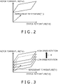
- FIG. 2 is a graph illustrating a method for identifying rotor temperature by a control apparatus of a comparative example
- FIG. 3 is a graph indicating a relationship between rotor temperature identified by the control apparatus 60 and rotation speed of the rotor 14.
- Tro indicates temperature of the rotor estimated by the control apparatus of the comparative example
- Tst indicates detected temperature of the coil 13 detected by the first temperature sensor 17
- Tr indicates refrigerant temperature (coolant temperature) detected by the second temperature sensor 25
- the control apparatus of the comparative example estimates Tro based on the following formula (1).
- Tro A 0 ⁇ Tr + B 0 ⁇ Tst + C 0
- Tro is positioned on one plane in three-dimensional space with Tro, Tst and Tr as the Z-axis, X-axis and Y-axis as shown in FIG. 2 , and is uniquely identified when Tst and Tr are decided.
- the control apparatus 60 of the present disclosure is adapted to estimate Tro based on the following formula (2) when A 1 , Bi and C 1 are constants, Tro indicates temperature of the rotor estimated by the control apparatus 60, Tst indicates detected temperature of the coil 13 detected by the first temperature sensor 17, Tr indicates refrigerant temperature (coolant temperature) detected by the second temperature sensor 25, and N indicates the rotation speed N of the rotor 14 detected by the resolver 18.
- C 1 is a positive constant, and Ci>0 is satisfied.
- Tro A 1 ⁇ Tr + B 1 ⁇ Tst + C 1 ⁇ N
- Tro is not positioned only on one plane that is stationary in the three-dimensional space with Tro, Tst, and Tr as the Z-axis, the X-axis and the Y-axis.
- the value of the rotation speed N increases, the plane on which Tro is positioned moves to the upper side indicated by an arrow A in the three-dimensional space, and the estimated temperature of the rotor 14 increases.
- the value of the rotation speed N decreases, the plane on which Tro is positioned moves to the lower side in the three-dimensional space, and the estimated temperature of the rotor 14 decreases.
- FIG. 4 is a graph showing a relationship among the actual temperature of the rotor 14, the estimated temperature of the rotor 14 estimated by the control apparatus 60, and the estimated temperature of the rotor 14 estimated by the control apparatus of the comparative example when the rotor 14 is rotating at a high speed.
- FIG. 5 is a graph showing a relationship among the actual temperature of the rotor 14, the estimated temperature of the rotor 14 estimated by the control apparatus 60, and the estimated temperature of the rotor 14 estimated by the control apparatus of the comparative example when the rotor 14 is rotating at a low speed.
- the estimated temperature of the rotor 14 estimated using the method of the present disclosure substantially corresponds to the actual temperature of the rotor 14 in the initial period from measurement starting time, while the estimated temperature of the rotor 14 estimated using the method of the comparative example is higher than the actual temperature of the rotor 14. Therefore, in the initial period from the measurement starting time in the high-speed rotation range, the actual temperature of the rotor 14 can be estimated with a higher accuracy by the method of the present disclosure than by the method of the comparative example.
- the method of the present disclosure and the method of the comparative example have a tendency that, when time passes after the measurement starting time, the estimated temperatures of the rotor 14 substantially correspond to each other, and the estimated temperatures are higher than the actual temperature of the rotor 14 to the same extent.
- the estimated temperature of the rotor 14 estimated using the method of the comparative example is significantly higher than the actual temperature of the rotor 14 in all the periods from the measurement starting time.
- the estimated temperature of the rotor 14 estimated using the method of the present disclosure is higher than the actual temperature of the rotor 14 in all the periods from the measurement starting time, the difference from the actual temperature is significantly reduced to about half of the difference from the actual temperature in the case of using the method of the comparative example in all the periods from the measurement starting time.
- FIG. 6 is a graph indicating a relationship between a rotation speed of the electric motor 10 and the maximum torque that the electric motor 10 is allowed to generate for each rotation speed.
- the dotted line is a line indicating a relationship between a rotation speed and the maximum torque when the temperature of the rotor 14 is T ⁇ °C
- the solid line is a line indicating a relationship between a rotation speed and the maximum torque when the temperature of the rotor 14 is T ⁇ °C (T ⁇ > T ⁇ ).
- torque allowed to be generated decreases as the rotation speed of the electric motor 10 increases. That is, when the rotation speed of the electric motor 10 increases, it becomes necessary to limit the maximum value of torque generated by the electric motor 10.
- the method of the comparative example that is, the method of estimating the temperature of the rotor 14 without consideration of the rotation speed of the electric motor 10
- generated torque is excessively limited even in the low-speed rotation range where a high torque is allowed. Therefore, it is not possible to make full use of the performance of the electric motor 10 in the low-speed rotation range, and it is not possible to cause the electric motor 10 to be efficiently driven in the low-speed rotation range.
- the temperature of the rotor 14 is estimated in consideration of the rotation speed of the electric motor 10. Therefore, as shown in FIG. 5 , in the low-speed rotation range the estimated temperature of the rotor 14 can be a temperature that is significantly lower than the estimated temperature of the method of the comparative example, and that is higher than the actual temperature of the rotor 14. As a result, it is possible to significantly increase the maximum torque that can be generated in the low-speed rotation range, and it is possible to cause the electric motor 10 to be very efficiently driven.
- the electric motor 10 is caused to operate at a high-speed rotation in limited cases, such as travel on an expressway. In normal travel, that is, in travel in town and the like, the electric motor 10 is often caused to operate at a low-speed rotation. Therefore, by mounting the control apparatus 60 of the present disclosure on a vehicle (which is not limited to the electric vehicle 1 but may be a hybrid car), it is possible to significantly increase the maximum torque that can be generated in the low-speed rotation range that occupies during travel, and it is possible to cause the electric motor 10 to be very efficiently driven and acquire remarkable operation and effects.
- a vehicle which is not limited to the electric vehicle 1 but may be a hybrid car
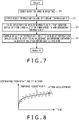
- FIG. 7 is a flowchart illustrating a procedure for estimating the temperature of the rotor 14 in the electric vehicle 1.
- the flow shown in Fig. 7 starts.
- the resolver 18 detects the rotation speed N of the rotor 14.
- the first temperature sensor 17 detects the coil temperature Tst
- the second temperature sensor 25 detects the refrigerant temperature Tr.
- the rotor temperature estimation unit 62a of the control apparatus 60 calculates the temperature Tro of the rotor 14 (corresponding to the temperature of the permanent magnets 15) based on the rotation speed N, the coil temperature Tst, the refrigerant temperature Tr, and the above formula (2) stored in the storage unit 64.
- the rotor temperature estimation unit 62a adjusts the amount of temperature change to an amount of temperature change according to a physical amount from the temperature Tro estimated the last time, that is, Tro one control cycle before, and the temperature Tro calculated at step S3, to decide the estimated temperature Tro of the rotor 14 this time.
- the adjustment can be performed, for example, using filtering, rate limit processing, moving average processing or the like.
- the temperature Tro of the rotor 14 is prevented from rising sharply from the estimated value last time.
- the final estimated temperature Tro of the rotor 14 this time may be decided based on the temperature Tro calculated at step S3 and the temperature Tro of the rotor 14 estimated last time, for example, using a publicly known Kalman filter or the like.
- a linear function is defined. Then, when the temperature change rate of Tro calculated at step S3 to the estimated temperature Tro last time exceeds the change rate of the linear function, the temperature change rate of the final estimated temperature Tro this time to the estimated temperature Tro last time is replaced with the change rate of the linear function.
- the final estimated temperature Tro this time is estimated not by using only the temperature Tro last time, but by calculating an average among a plurality of temperatures Tro before this time and Tro calculated at step S3.
- the adjustments require at least the estimated temperature Tro last time, but the estimated temperature Tro last time does not exist at the time of the first temperature estimation after the electric vehicle 1 is driven.
- the coil temperature detected by the first temperature sensor 17 may be set as the estimated temperature Tro at the time of being driven (at the time of the power source being turned on), or the refrigerant temperature detected by the second temperature sensor 25 may be set as the estimated temperature Tro at the time of being driven.
- the estimated temperature Tro at the time of being driven may be highly accurately estimated. A method for estimating such an estimated temperature Tro at the time of being driven will be described later in detail.
- the adjustment of the amount of temperature change is performed for the following reason. For example, when a wheel spin occurs in a case where a driver instantaneously steps on the accelerator too much by mistake, the rotation speed increases sharply only for a moment, and the estimated temperature of the rotor 14 instantaneously increases accompanying that. However, the actual temperature of the rotor 14 does not increase only by the rotation speed of the rotor 14 increasing only for a moment. The adjustment of the amount of temperature change is performed to exclude such a case.
- FIG. 8 is a diagram illustrating an overview of change in the estimated temperature before and after the temperature adjustment at step S4. Note that in FIG. 8 , the broken line indicates estimated temperature before the temperature adjustment at step S4, and the solid line indicates estimated temperature after the temperature adjustment at step S4. As shown in FIG. 8 , by performing step S4, it is possible to reduce local unevenness in the graph indicating fluctuation of estimated temperature relative to time, smooth the graph, and increase the accuracy of the estimated temperature.
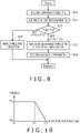
- FIG. 9 is a flowchart illustrating an operation procedure at the time of the control apparatus 60 controlling the output characteristic of the electric motor 10.
- the electric motor control unit 62d acquires a command torque Tra, for example, based on a signal from the accelerator sensor 8 (see FIG. 1 ).
- the rotor temperature estimation unit 62a estimates the temperature of the rotor 14 by the procedure described using FIG. 7 , and the flow transitions to step S13.
- step S13 the electric motor control unit 62d judges whether the temperature Tro of the rotor 14 estimated by the rotor temperature estimation unit 62a is higher than a temperature threshold T1 stored in the storage unit 64. If a negative judgment is made at step S13, and the electric motor control unit 62d judges that the temperature Tro is below the temperature threshold T1, the flow transitions to step S14, where the electric motor control unit 62d outputs a PWM signal for generating a torque Tra, to the inverter 30, and the electric motor 10 generates the torque Tra. After that, the control returns, and step S11 and the subsequent steps are repeated.
- step S15 the flow transitions to step S15, where an allowable torque Trb at the estimated temperature Tro of the rotor 14 is calculated.
- the allowable torque Trb is calculated using a torque limit map.
- FIG. 10 is a graph indicating an example of a relationship between temperature and torque, which can be used as a torque limit map, and is a graph indicating a relationship between temperature and the maximum torque that can be generated at the temperature.
- TrA indicates the maximum torque that can be generated by the electric motor
- TrB indicates a limit torque at the time when the estimated temperature of the rotor 14 is T2.
- T1 indicates a torque limit starting temperature.
- the maximum value TrA of torque generated by the electric motor 10 is the maximum torque that the electric motor 10 can generate until the temperature of the rotor 14 reaches the temperature threshold T1.
- the maximum value of torque generated by the electric motor 10 decreases according to a linear function as temperature increases.
- the maximum value of torque generated by the electric motor 10 decreases according to a linear function as temperature increases.
- the maximum value of the torque generated by the electric motor 10 may decrease according to any function other than a linear function as temperature increases.
- the maximum value of the torque generated by the electric motor 10 may decrease according to such a broken-line function that has a leveling off as temperature increases, or may decrease according to a quadratic or higher-order function.
- step S16 after step S15, the electric motor control unit 62d outputs a PWM signal for generating the torque Trb calculated at step S15, to the inverter 30, and the electric motor 10 generates the torque Trb.
- the control returns, and step S11 and the subsequent steps are repeated.
- the control of the electric motor 10 shown in FIG. 9 ends, for example, when the electric vehicle 1 reaches a destination, and electric power to the electric motor 10 is cut off.
- the start-up temperature estimation unit 62c estimates the initial temperature of the rotor 14 as follows. As shown in FIG. 11 , that is, as shown by a relationship between the magnet temperature of the permanent magnets 15 of the rotor 14 and the electric power source cutoff time during which the electric power source for the electric motor 10 is cut off, there is correlation between magnet temperature and the electric power source cutoff time.
- the start-up temperature estimation unit 62c estimates the initial temperature of the rotor 14 to be referred to at the time of restarting the electric vehicle 1, based on information about the estimated temperature Tro of the rotor 14 immediately before electric power source cutoff is executed, information about electric power source cutoff time from the timer 5, and map information defining correlation between the magnet temperature and the electric power source cutoff time, which is stored in the storage unit 64 in advance.
- the technique of the present disclosure it is possible to accurately estimate the initial temperature of the rotor 14 to be referred to at the time of restarting up the electric vehicle 1, using the start-up temperature estimation unit 62c. Therefore, unlike the case of holding the last time value without estimating the initial temperature of the permanent magnets, like the line indicated by "a” in FIG. 11 , the estimated temperature of the permanent magnets 15 does not become excessively higher than the actual temperature, and it is easy to cause the electric motor 10 to operate efficiently from when the electric motor 10 is restarted up. Further, unlike the case of causing the initial temperature of the permanent magnets to be a constant temperature without estimation, like the line indicated by "b" in FIG. 11 , it is possible to prevent the estimated temperature of the permanent magnets 15 from being lower than the actual temperature and protect the magnetic force of the permanent magnets 15.
- the electric power source cutoff time may be estimated from the amount of temperature change of the first temperature sensor 17 that detects the temperature of the stator 12, the second temperature sensor 25 that detects the refrigerant temperature, or any of other various kinds of temperature sensors mounted on the electric vehicle 1.
- FIG. 12 there is correlation between the electric power source cutoff time and a value of temperature change of the stator 12 or the refrigerant. Therefore, by detecting the value of temperature change by the first temperature sensor 17 or the second temperature sensor 25, the electric power source cutoff time can be estimated. Therefore, since the initial temperature can be estimated without using the timer 5, the timer 5 may be deleted to reduce the manufacturing cost.
- the initial temperature of the rotor 14 may be estimated using only one of detected temperatures of the first temperature sensor 17 and the second temperature sensor 25. However, by calculating an average of a plurality of initial temperatures of the rotor 14 estimated based on detected values of a plurality of sensors and setting the average value as the initial temperature, it is easy to reduce the difference between the initial temperature and the actual temperature of the rotor 14 at the time of restarting up the electric power source, and to highly accurately estimate the initial temperature of the rotor 14.
- control apparatus 60 may control the drive condition of the electric motor 10 using an estimated rotor temperature.
- control apparatus 60 may acquire a required performance value C1 at step S21.
- the required performance value C1 may include, for example, one or more of a voltage applied to the electric motor 10, a carrier frequency that decides a pulse width modulation cycle in PWM control, an amount of oil to be circulated by on/off control of a starting switch for the electric oil pump 23, an amount of cooling air flow based on the duty ratio of a radiator fan, an amount of cooling water circulation based on the duty ratio of a water pump, and an amount of air that passes through the vehicle based on opening/closing of a grill shutter.
- the rotor temperature estimation unit 62a estimates the temperature of the rotor 14 using the procedure described using FIG. 7 , and the flow transitions to step S23.
- the control apparatus 60 judges whether the temperature Tro of the rotor 14 estimated by the rotor temperature estimation unit 62a is higher than a temperature threshold T2 stored in the storage unit 64. If a negative judgment is made at step S23, and the control apparatus 60 judges that the temperature Tro is equal to or lower than the temperature threshold T2, the flow transitions to step S24, where the control apparatus 60 performs control to realize the required performance value C1. After that, the control returns, and step S21 and the subsequent steps are repeated.
- step S23 if a positive judgment is made at step S23, and the control apparatus 60 judges that the temperature Tro has exceeded the temperature threshold T2, the flow transitions to step S25, where a required performance value C2 at the estimated temperature Tro of the rotor 14 is calculated.
- a required performance value C2 at the estimated temperature Tro of the rotor 14 is calculated.
- an allowable voltage value, an allowable carrier frequency, whether the electric oil pump 23 is to be driven or not, an allowable duty ratio of the radiator fan, an allowable duty ratio of the water pump, and whether the grill shutter is to be opened or not are calculated or decided, using at least one of a program, data, and map stored in the storage unit 64.
- step S26 after step S25, the control apparatus 60 performs control to realize the required performance value C2. After that, the control returns, and step S21 and the subsequent steps are repeated.
- the temperature of the electric motor 10 can be decreased. Further, the temperature of the electric motor 10 can be also decreased by changing the allowable carrier frequency, driving the electric oil pump 23, increasing the allowable duty ratio of the radiator fan, increasing the allowable duty ratio of the water pump, or opening the grill shutter. Therefore, by performing the control, it is possible to increase the maximum value of torque that can be generated by the electric motor 10, and in particular, it is possible to significantly increase the maximum value of torque that can be generated in the low-speed rotation range and cause the electric motor 10 to operate efficiently.
- the control apparatus 60 of the present disclosure controls the electric motor 10 mounted on the electric vehicle 1.
- the control apparatus 60 is a control apparatus including: the rotor temperature estimation unit 62a estimating a temperature of the rotor 14 based on stator temperature information from the first temperature sensor (stator temperature identification unit) 17 for identifying the temperature of the stator 12, refrigerant temperature information from the second temperature sensor (refrigerant temperature identification unit) 25 for identifying the temperature of refrigerant used to cool the electric motor 10, and rotation speed information about the rotor 14 from the resolver (rotation speed identification unit) 18 for identifying the rotation speed of the rotor 14; and the electric motor control unit 62d controlling at least one of the output characteristic and the drive condition of the electric motor 10 based on the temperature of the rotor 14 estimated by the rotor temperature estimation unit 62a.
- the control apparatus 60 controls at least one of the output characteristic and the drive condition of the electric motor 10 in consideration of the rotation speed of the rotor 14 in addition to the stator temperature information and the refrigerant temperature information. Therefore, it is possible to prevent output from being excessively limited when the electric motor 10 is rotating at a low speed, and it is possible to cause the electric motor 10 to operate efficiently at both the time of rotating at a low speed and the time of rotating at a high speed.
- the rotor 14 may include the permanent magnets 15.
- the control unit 62 may control at least one of the output characteristic and the drive condition of the electric motor 10 so that the permanent magnets 15 are not demagnetized, based on the temperature of the rotor 14.
- control apparatus 60 may include: the electric power source cutoff time identification unit 62b identifying electric power source cutoff time during which the electric power source for the electric vehicle 1 is cut off; and the start-up temperature estimation unit 62c estimating the temperature of the rotor 14 at the time of energizing the electric vehicle 1 for which the electric power source cutoff time has ended, based on the electric power source cutoff time and a temperature of the rotor 14, estimated by the rotor temperature estimation unit 62a, immediately before cutting off the electric power source.
- the present configuration it is possible to estimate the temperature of the rotor 14 at the time of the vehicle being started up. Therefore, it is possible to cause the electric motor 10 to operate efficiently from when the vehicle is started up, and it is possible to cause the electric motor 10 to output a high torque from when the vehicle is started up. Therefore, it is possible to realize a motive power mechanism that is superior in responsiveness to an operation from when the vehicle is started up.
- the above formula (2) is used to estimate the temperature of the rotor 14, and a term proportional to the rotation speed N is added to the formula for calculating provisional Tro.
- the formula for calculating the provisional Tro may be the above formula (2) to which a constant is added.
- the formula for calculating the provisional Tro may include a function F(N) that is defined with the rotation speed N and that is not a linear function.
- F(N) may include a quadratic or higher-order function, or may include one or more functions among a trigonometric function, an exponential function, a logarithmic function, and special functions.
- control apparatus of the present disclosure may control both the output characteristic, and the drive condition, of the electric motor, based on the temperature of the rotator estimated by the rotor temperature estimation unit.
- stator temperature identification unit is the first temperature sensor 17, the refrigerant temperature identification unit is the second temperature sensor 25, and the rotation speed identification unit is the resolver 18.
- the stator temperature identification unit, the refrigerant temperature identification unit and the rotation speed identification unit may estimate one or more items of physical information among the temperature of the stator, the temperature of the refrigerant, and the rotation speed of the rotor, based on one or more items of physical information related to the electric motor, for example, one or more items of physical information among voltage applied to the electric motor, electric power supplied by the electric motor, a current supplied to the electric motor, the duty ratio of the radiator fan, and the duty ratio of the water pump, and software.
- the vehicle may be a hybrid car provided with an internal-combustion engine in addition to an electric motor.
- the electric motor 10 is provided with the permanent magnets 15.
- the electric motor may be an electric motor without permanent magnets, for example, an induction motor, an SR (Switched Reluctance) motor, or the like.
- an electric motor reduction in efficiency accompanying rise of conductor temperature in the rotor is generally known. Therefore, by using the technique of the present disclosure, it is possible, for example, even in an electric motor without permanent magnets, to effectively suppress or prevent efficiency reduction of the electric motor by estimating the temperature of the rotor and causing the cooling pump to operate when a certain temperature is exceeded.
- the temperature of the rotor of an electric motor rises due to iron loss generated by rotation, and heat received from the stator.
Landscapes
- Engineering & Computer Science (AREA)
- Transportation (AREA)
- Mechanical Engineering (AREA)
- Power Engineering (AREA)
- Physics & Mathematics (AREA)
- Automation & Control Theory (AREA)
- Mathematical Physics (AREA)
- Life Sciences & Earth Sciences (AREA)
- Sustainable Development (AREA)
- Sustainable Energy (AREA)
- General Physics & Mathematics (AREA)
- Electric Propulsion And Braking For Vehicles (AREA)
- Arrangement Or Mounting Of Propulsion Units For Vehicles (AREA)
- Control Of Electric Motors In General (AREA)
Applications Claiming Priority (1)
| Application Number | Priority Date | Filing Date | Title |
|---|---|---|---|
| JP2021073551A JP2022167625A (ja) | 2021-04-23 | 2021-04-23 | 電動機の制御装置、及び車両 |
Publications (2)
| Publication Number | Publication Date |
|---|---|
| EP4079564A1 true EP4079564A1 (fr) | 2022-10-26 |
| EP4079564B1 EP4079564B1 (fr) | 2024-01-24 |
Family
ID=81307314
Family Applications (1)
| Application Number | Title | Priority Date | Filing Date |
|---|---|---|---|
| EP22167766.9A Active EP4079564B1 (fr) | 2021-04-23 | 2022-04-12 | Appareil de commande pour moteur électrique et véhicule |
Country Status (4)
| Country | Link |
|---|---|
| US (1) | US11807250B2 (fr) |
| EP (1) | EP4079564B1 (fr) |
| JP (1) | JP2022167625A (fr) |
| CN (1) | CN115230483A (fr) |
Families Citing this family (1)
| Publication number | Priority date | Publication date | Assignee | Title |
|---|---|---|---|---|
| CN117013924B (zh) * | 2023-06-25 | 2024-03-19 | 昆山华辰电动科技有限公司 | 水下推进电机控制器功率器件温度保护方法及装置 |
Citations (6)
| Publication number | Priority date | Publication date | Assignee | Title |
|---|---|---|---|---|
| JPS6026815B2 (ja) | 1980-02-27 | 1985-06-26 | 川崎製鉄株式会社 | 2相ステンレス鋼帯の製造方法 |
| EP2058941A1 (fr) * | 2007-03-29 | 2009-05-13 | Toyota Jidosha Kabushiki Kaisha | Dispositif de commande de moteur, procédé de commande, et programme de commande |
| JP2013085388A (ja) * | 2011-10-11 | 2013-05-09 | Nissan Motor Co Ltd | モータ温度検出装置及び駆動力制御装置 |
| US20140126606A1 (en) * | 2012-11-02 | 2014-05-08 | Honda Motor Co., Ltd. | Method of estimating magnet temperature for rotary electric machinery |
| US20160344268A1 (en) * | 2015-05-19 | 2016-11-24 | Honda Motor Co., Ltd. | Temperature estimation apparatus for rotating electric machine |
| WO2021075186A1 (fr) * | 2019-10-18 | 2021-04-22 | 日立Astemo株式会社 | Dispositif de commande de moteur, estimateur de température d'aimant et procédé d'estimation de température d'aimant |
Family Cites Families (9)
| Publication number | Priority date | Publication date | Assignee | Title |
|---|---|---|---|---|
| US8212510B2 (en) * | 2009-11-09 | 2012-07-03 | GM Global Technology Operations LLC | Fiber optically communicated motor temperature and position signals |
| JP6026815B2 (ja) | 2012-08-22 | 2016-11-16 | トヨタ自動車株式会社 | 電動車両の駆動制御装置 |
| CN104852356B (zh) * | 2014-02-17 | 2018-09-21 | 伊顿公司 | 电动机的控制保护装置 |
| JP6740114B2 (ja) | 2016-12-22 | 2020-08-12 | 株式会社デンソー | モータシステム |
| US10428682B2 (en) * | 2017-01-13 | 2019-10-01 | Hamilton Sundstrand Corporation | Electric motor arrangements for gas turbine engines |
| WO2019039211A1 (fr) * | 2017-08-21 | 2019-02-28 | ソニー株式会社 | Dispositif de moteur, et corps mobile entraîné par un moteur |
| JP6701158B2 (ja) * | 2017-12-22 | 2020-05-27 | 株式会社Subaru | 車両の制御装置及び車両の制御方法 |
| CN109861172B (zh) * | 2019-03-29 | 2020-07-03 | 北京经纬恒润科技有限公司 | 电机过热保护方法及装置 |
| AU2020283812A1 (en) * | 2019-05-24 | 2021-12-16 | Alakai Technologies Corporation | Integrated multimode thermal energy transfer system, method and apparatus for clean fuel electric multirotor aircraft |
-
2021
- 2021-04-23 JP JP2021073551A patent/JP2022167625A/ja active Pending
-
2022
- 2022-04-12 EP EP22167766.9A patent/EP4079564B1/fr active Active
- 2022-04-20 CN CN202210417330.5A patent/CN115230483A/zh active Pending
- 2022-04-22 US US17/660,311 patent/US11807250B2/en active Active
Patent Citations (6)
| Publication number | Priority date | Publication date | Assignee | Title |
|---|---|---|---|---|
| JPS6026815B2 (ja) | 1980-02-27 | 1985-06-26 | 川崎製鉄株式会社 | 2相ステンレス鋼帯の製造方法 |
| EP2058941A1 (fr) * | 2007-03-29 | 2009-05-13 | Toyota Jidosha Kabushiki Kaisha | Dispositif de commande de moteur, procédé de commande, et programme de commande |
| JP2013085388A (ja) * | 2011-10-11 | 2013-05-09 | Nissan Motor Co Ltd | モータ温度検出装置及び駆動力制御装置 |
| US20140126606A1 (en) * | 2012-11-02 | 2014-05-08 | Honda Motor Co., Ltd. | Method of estimating magnet temperature for rotary electric machinery |
| US20160344268A1 (en) * | 2015-05-19 | 2016-11-24 | Honda Motor Co., Ltd. | Temperature estimation apparatus for rotating electric machine |
| WO2021075186A1 (fr) * | 2019-10-18 | 2021-04-22 | 日立Astemo株式会社 | Dispositif de commande de moteur, estimateur de température d'aimant et procédé d'estimation de température d'aimant |
Also Published As
| Publication number | Publication date |
|---|---|
| CN115230483A (zh) | 2022-10-25 |
| EP4079564B1 (fr) | 2024-01-24 |
| US20220340147A1 (en) | 2022-10-27 |
| JP2022167625A (ja) | 2022-11-04 |
| US11807250B2 (en) | 2023-11-07 |
Similar Documents
| Publication | Publication Date | Title |
|---|---|---|
| JP4572907B2 (ja) | モータ制御装置、制御方法及び制御プログラム | |
| JP4215025B2 (ja) | 車両用発電制御装置 | |
| US10309842B2 (en) | Magnet temperature estimation device for rotating electric machine and magnet temperature estimation method for rotating electric machine | |
| JP5695013B2 (ja) | 回転電機の磁石温度推定装置及び磁石温度推定方法 | |
| US9331554B2 (en) | System and method for controlling motor | |
| EP4079564A1 (fr) | Appareil de commande pour moteur électrique et véhicule | |
| JP5760865B2 (ja) | 車両用モータ温度検出装置 | |
| US11575340B2 (en) | Method for continuous condition monitoring of an electric motor | |
| JP2014131392A (ja) | インバータ制御装置及びインバータ装置 | |
| JP6740114B2 (ja) | モータシステム | |
| JP6642462B2 (ja) | 回転電機の温度推定システム | |
| EP3503377B1 (fr) | Dispositif de détection de surchauffe | |
| US12088154B2 (en) | Cooling control device, electric system, and cooling control method | |
| JP4924066B2 (ja) | モータ制御装置、及びモータ制御方法 | |
| JP2008187861A (ja) | モータ制御装置、モータ制御方法及び車両用駆動制御装置 | |
| JP2011244636A (ja) | 回転電機制御装置 | |
| JP6638637B2 (ja) | 回転電機の温度推定システム | |
| JP6614798B2 (ja) | 回転電機の温度制御装置 | |
| JP6865133B2 (ja) | 回転電機の冷却装置、および回転電機の冷却方法 | |
| JP6090364B2 (ja) | 永久磁石型同期モータを搭載した車両の制御装置及び永久磁石型同期モータの上限温度の設定方法 | |
| JP7471466B2 (ja) | 回転電機の制御装置および制御方法 | |
| US20230402955A1 (en) | Device and method for estimating internal temperature of electric motor and control device for electric motor | |
| US20230238911A1 (en) | Motor control system and motor control method | |
| US20220321049A1 (en) | Method for detecting a blockage of an electric motor | |
| CN115771394A (zh) | 车辆 |
Legal Events
| Date | Code | Title | Description |
|---|---|---|---|
| PUAI | Public reference made under article 153(3) epc to a published international application that has entered the european phase |
Free format text: ORIGINAL CODE: 0009012 |
|
| STAA | Information on the status of an ep patent application or granted ep patent |
Free format text: STATUS: REQUEST FOR EXAMINATION WAS MADE |
|
| 17P | Request for examination filed |
Effective date: 20220412 |
|
| AK | Designated contracting states |
Kind code of ref document: A1 Designated state(s): AL AT BE BG CH CY CZ DE DK EE ES FI FR GB GR HR HU IE IS IT LI LT LU LV MC MK MT NL NO PL PT RO RS SE SI SK SM TR |
|
| GRAP | Despatch of communication of intention to grant a patent |
Free format text: ORIGINAL CODE: EPIDOSNIGR1 |
|
| STAA | Information on the status of an ep patent application or granted ep patent |
Free format text: STATUS: GRANT OF PATENT IS INTENDED |
|
| INTG | Intention to grant announced |
Effective date: 20230828 |
|
| GRAS | Grant fee paid |
Free format text: ORIGINAL CODE: EPIDOSNIGR3 |
|
| GRAA | (expected) grant |
Free format text: ORIGINAL CODE: 0009210 |
|
| STAA | Information on the status of an ep patent application or granted ep patent |
Free format text: STATUS: THE PATENT HAS BEEN GRANTED |
|
| AK | Designated contracting states |
Kind code of ref document: B1 Designated state(s): AL AT BE BG CH CY CZ DE DK EE ES FI FR GB GR HR HU IE IS IT LI LT LU LV MC MK MT NL NO PL PT RO RS SE SI SK SM TR |
|
| REG | Reference to a national code |
Ref country code: GB Ref legal event code: FG4D |
|
| REG | Reference to a national code |
Ref country code: CH Ref legal event code: EP |
|
| REG | Reference to a national code |
Ref country code: IE Ref legal event code: FG4D |
|
| REG | Reference to a national code |
Ref country code: DE Ref legal event code: R096 Ref document number: 602022001656 Country of ref document: DE |
|
| REG | Reference to a national code |
Ref country code: LT Ref legal event code: MG9D |
|
| P01 | Opt-out of the competence of the unified patent court (upc) registered |
Effective date: 20240419 |
|
| REG | Reference to a national code |
Ref country code: NL Ref legal event code: MP Effective date: 20240124 |
|
| REG | Reference to a national code |
Ref country code: DE Ref legal event code: R084 Ref document number: 602022001656 Country of ref document: DE |
|
| PG25 | Lapsed in a contracting state [announced via postgrant information from national office to epo] |
Ref country code: NL Free format text: LAPSE BECAUSE OF FAILURE TO SUBMIT A TRANSLATION OF THE DESCRIPTION OR TO PAY THE FEE WITHIN THE PRESCRIBED TIME-LIMIT Effective date: 20240124 |
|
| PG25 | Lapsed in a contracting state [announced via postgrant information from national office to epo] |
Ref country code: NL Free format text: LAPSE BECAUSE OF FAILURE TO SUBMIT A TRANSLATION OF THE DESCRIPTION OR TO PAY THE FEE WITHIN THE PRESCRIBED TIME-LIMIT Effective date: 20240124 |
|
| PG25 | Lapsed in a contracting state [announced via postgrant information from national office to epo] |
Ref country code: IS Free format text: LAPSE BECAUSE OF FAILURE TO SUBMIT A TRANSLATION OF THE DESCRIPTION OR TO PAY THE FEE WITHIN THE PRESCRIBED TIME-LIMIT Effective date: 20240524 |
|
| PG25 | Lapsed in a contracting state [announced via postgrant information from national office to epo] |
Ref country code: LT Free format text: LAPSE BECAUSE OF FAILURE TO SUBMIT A TRANSLATION OF THE DESCRIPTION OR TO PAY THE FEE WITHIN THE PRESCRIBED TIME-LIMIT Effective date: 20240124 |
|
| PGFP | Annual fee paid to national office [announced via postgrant information from national office to epo] |
Ref country code: DE Payment date: 20240313 Year of fee payment: 3 |
|
| PG25 | Lapsed in a contracting state [announced via postgrant information from national office to epo] |
Ref country code: GR Free format text: LAPSE BECAUSE OF FAILURE TO SUBMIT A TRANSLATION OF THE DESCRIPTION OR TO PAY THE FEE WITHIN THE PRESCRIBED TIME-LIMIT Effective date: 20240425 |
|
| REG | Reference to a national code |
Ref country code: AT Ref legal event code: MK05 Ref document number: 1651929 Country of ref document: AT Kind code of ref document: T Effective date: 20240124 |
|
| PG25 | Lapsed in a contracting state [announced via postgrant information from national office to epo] |
Ref country code: HR Free format text: LAPSE BECAUSE OF FAILURE TO SUBMIT A TRANSLATION OF THE DESCRIPTION OR TO PAY THE FEE WITHIN THE PRESCRIBED TIME-LIMIT Effective date: 20240124 Ref country code: RS Free format text: LAPSE BECAUSE OF FAILURE TO SUBMIT A TRANSLATION OF THE DESCRIPTION OR TO PAY THE FEE WITHIN THE PRESCRIBED TIME-LIMIT Effective date: 20240424 |
|
| PG25 | Lapsed in a contracting state [announced via postgrant information from national office to epo] |
Ref country code: ES Free format text: LAPSE BECAUSE OF FAILURE TO SUBMIT A TRANSLATION OF THE DESCRIPTION OR TO PAY THE FEE WITHIN THE PRESCRIBED TIME-LIMIT Effective date: 20240124 |
|
| PG25 | Lapsed in a contracting state [announced via postgrant information from national office to epo] |
Ref country code: AT Free format text: LAPSE BECAUSE OF FAILURE TO SUBMIT A TRANSLATION OF THE DESCRIPTION OR TO PAY THE FEE WITHIN THE PRESCRIBED TIME-LIMIT Effective date: 20240124 |
|
| PG25 | Lapsed in a contracting state [announced via postgrant information from national office to epo] |
Ref country code: RS Free format text: LAPSE BECAUSE OF FAILURE TO SUBMIT A TRANSLATION OF THE DESCRIPTION OR TO PAY THE FEE WITHIN THE PRESCRIBED TIME-LIMIT Effective date: 20240424 Ref country code: NO Free format text: LAPSE BECAUSE OF FAILURE TO SUBMIT A TRANSLATION OF THE DESCRIPTION OR TO PAY THE FEE WITHIN THE PRESCRIBED TIME-LIMIT Effective date: 20240424 Ref country code: LT Free format text: LAPSE BECAUSE OF FAILURE TO SUBMIT A TRANSLATION OF THE DESCRIPTION OR TO PAY THE FEE WITHIN THE PRESCRIBED TIME-LIMIT Effective date: 20240124 Ref country code: IS Free format text: LAPSE BECAUSE OF FAILURE TO SUBMIT A TRANSLATION OF THE DESCRIPTION OR TO PAY THE FEE WITHIN THE PRESCRIBED TIME-LIMIT Effective date: 20240524 Ref country code: HR Free format text: LAPSE BECAUSE OF FAILURE TO SUBMIT A TRANSLATION OF THE DESCRIPTION OR TO PAY THE FEE WITHIN THE PRESCRIBED TIME-LIMIT Effective date: 20240124 Ref country code: GR Free format text: LAPSE BECAUSE OF FAILURE TO SUBMIT A TRANSLATION OF THE DESCRIPTION OR TO PAY THE FEE WITHIN THE PRESCRIBED TIME-LIMIT Effective date: 20240425 Ref country code: FI Free format text: LAPSE BECAUSE OF FAILURE TO SUBMIT A TRANSLATION OF THE DESCRIPTION OR TO PAY THE FEE WITHIN THE PRESCRIBED TIME-LIMIT Effective date: 20240124 Ref country code: ES Free format text: LAPSE BECAUSE OF FAILURE TO SUBMIT A TRANSLATION OF THE DESCRIPTION OR TO PAY THE FEE WITHIN THE PRESCRIBED TIME-LIMIT Effective date: 20240124 Ref country code: BG Free format text: LAPSE BECAUSE OF FAILURE TO SUBMIT A TRANSLATION OF THE DESCRIPTION OR TO PAY THE FEE WITHIN THE PRESCRIBED TIME-LIMIT Effective date: 20240124 Ref country code: AT Free format text: LAPSE BECAUSE OF FAILURE TO SUBMIT A TRANSLATION OF THE DESCRIPTION OR TO PAY THE FEE WITHIN THE PRESCRIBED TIME-LIMIT Effective date: 20240124 |
|
| PG25 | Lapsed in a contracting state [announced via postgrant information from national office to epo] |
Ref country code: PL Free format text: LAPSE BECAUSE OF FAILURE TO SUBMIT A TRANSLATION OF THE DESCRIPTION OR TO PAY THE FEE WITHIN THE PRESCRIBED TIME-LIMIT Effective date: 20240124 Ref country code: PT Free format text: LAPSE BECAUSE OF FAILURE TO SUBMIT A TRANSLATION OF THE DESCRIPTION OR TO PAY THE FEE WITHIN THE PRESCRIBED TIME-LIMIT Effective date: 20240524 |
|
| PG25 | Lapsed in a contracting state [announced via postgrant information from national office to epo] |
Ref country code: SE Free format text: LAPSE BECAUSE OF FAILURE TO SUBMIT A TRANSLATION OF THE DESCRIPTION OR TO PAY THE FEE WITHIN THE PRESCRIBED TIME-LIMIT Effective date: 20240124 Ref country code: PT Free format text: LAPSE BECAUSE OF FAILURE TO SUBMIT A TRANSLATION OF THE DESCRIPTION OR TO PAY THE FEE WITHIN THE PRESCRIBED TIME-LIMIT Effective date: 20240524 Ref country code: PL Free format text: LAPSE BECAUSE OF FAILURE TO SUBMIT A TRANSLATION OF THE DESCRIPTION OR TO PAY THE FEE WITHIN THE PRESCRIBED TIME-LIMIT Effective date: 20240124 Ref country code: LV Free format text: LAPSE BECAUSE OF FAILURE TO SUBMIT A TRANSLATION OF THE DESCRIPTION OR TO PAY THE FEE WITHIN THE PRESCRIBED TIME-LIMIT Effective date: 20240124 |