EP4078106B1 - Dosiervorrichtung sowie verfahren zur abgabe einer fliessfähigen substanz - Google Patents
Dosiervorrichtung sowie verfahren zur abgabe einer fliessfähigen substanz Download PDFInfo
- Publication number
- EP4078106B1 EP4078106B1 EP20833877.2A EP20833877A EP4078106B1 EP 4078106 B1 EP4078106 B1 EP 4078106B1 EP 20833877 A EP20833877 A EP 20833877A EP 4078106 B1 EP4078106 B1 EP 4078106B1
- Authority
- EP
- European Patent Office
- Prior art keywords
- control chamber
- opening
- dosing device
- cap
- closing part
- Prior art date
- Legal status (The legal status is an assumption and is not a legal conclusion. Google has not performed a legal analysis and makes no representation as to the accuracy of the status listed.)
- Active
Links
Images




Classifications
-
- G—PHYSICS
- G01—MEASURING; TESTING
- G01F—MEASURING VOLUME, VOLUME FLOW, MASS FLOW OR LIQUID LEVEL; METERING BY VOLUME
- G01F11/00—Apparatus requiring external operation adapted at each repeated and identical operation to measure and separate a predetermined volume of fluid or fluent solid material from a supply or container, without regard to weight, and to deliver it
- G01F11/10—Apparatus requiring external operation adapted at each repeated and identical operation to measure and separate a predetermined volume of fluid or fluent solid material from a supply or container, without regard to weight, and to deliver it with measuring chambers moved during operation
- G01F11/26—Apparatus requiring external operation adapted at each repeated and identical operation to measure and separate a predetermined volume of fluid or fluent solid material from a supply or container, without regard to weight, and to deliver it with measuring chambers moved during operation wherein the measuring chamber is filled and emptied by tilting or inverting the supply vessel, e.g. bottle-emptying apparatus
- G01F11/262—Apparatus requiring external operation adapted at each repeated and identical operation to measure and separate a predetermined volume of fluid or fluent solid material from a supply or container, without regard to weight, and to deliver it with measuring chambers moved during operation wherein the measuring chamber is filled and emptied by tilting or inverting the supply vessel, e.g. bottle-emptying apparatus for liquid or semi-liquid
- G01F11/263—Apparatus requiring external operation adapted at each repeated and identical operation to measure and separate a predetermined volume of fluid or fluent solid material from a supply or container, without regard to weight, and to deliver it with measuring chambers moved during operation wherein the measuring chamber is filled and emptied by tilting or inverting the supply vessel, e.g. bottle-emptying apparatus for liquid or semi-liquid with valves
-
- G—PHYSICS
- G01—MEASURING; TESTING
- G01F—MEASURING VOLUME, VOLUME FLOW, MASS FLOW OR LIQUID LEVEL; METERING BY VOLUME
- G01F11/00—Apparatus requiring external operation adapted at each repeated and identical operation to measure and separate a predetermined volume of fluid or fluent solid material from a supply or container, without regard to weight, and to deliver it
- G01F11/02—Apparatus requiring external operation adapted at each repeated and identical operation to measure and separate a predetermined volume of fluid or fluent solid material from a supply or container, without regard to weight, and to deliver it with measuring chambers which expand or contract during measurement
- G01F11/04—Apparatus requiring external operation adapted at each repeated and identical operation to measure and separate a predetermined volume of fluid or fluent solid material from a supply or container, without regard to weight, and to deliver it with measuring chambers which expand or contract during measurement of the free-piston type
- G01F11/06—Apparatus requiring external operation adapted at each repeated and identical operation to measure and separate a predetermined volume of fluid or fluent solid material from a supply or container, without regard to weight, and to deliver it with measuring chambers which expand or contract during measurement of the free-piston type with provision for varying the stroke of the piston
Definitions
- the invention relates to a dosing device and a method for dispensing a flowable substance.
- a dosing device for dispensing a controlled amount of liquid is, for example, from the document WO2018/080966A1 known.
- This dosing device is used to dispense a defined amount of liquid from a container, the container having a nozzle to which the dosing device can be connected by screwing on.
- This metering device has the disadvantages that its production is relatively complex and therefore relatively expensive, and that metering is not carried out in a satisfactorily reproducible manner under certain circumstances. In addition, the dose is only delivered when the container is squeezed.
- the document US2331659 discloses another metering device.
- This dosing device has, among other things, the disadvantages that the amount of liquid dispensed is fixed and cannot be changed, and that the dosing device has a valve cover which has to be closed by hand after the amount of liquid has been dispensed, so that the hand or fingers are damaged when closing it be contaminated by any residues of the liquid that may be present.
- the object of the invention is therefore to design a more advantageous dosing device for dispensing a controlled amount of a flowable substance, which in particular has improved dosing properties. It is also an object of the invention to design a more advantageous method for dispensing a controlled amount of a flowable substance.
- the dependent claims 2 to 18 relate to further advantageous embodiments.
- the problem is further solved with a method having the features of claim 19.
- the dependent claims 20 to 22 relate to further advantageous method steps.
- a dosing device for dispensing a flowable substance comprising a cap having a supply space which can be connected to a container or a supply in a fluid-conducting manner, as well as comprising a control chamber, a closing part and a pouring opening, the control chamber forming an interior space , in in which the closing part is arranged, the closing part being rotatably mounted about a pivot axis, the closing part dividing the interior of the control chamber into a flow chamber and a partial control chamber, the flow chamber conductively connecting the flowable substance to the pouring opening, the control chamber having an exchange opening , via which the feed space, the flowable substance is conductively connected to the partial control chamber, and wherein the control chamber has a control chamber inlet opening, via which the feed space, depending on the position of the closing part, is conductively connected to either the flow chamber or the flowable substance to the partial control chamber, and wherein the closing part is rotatable up to a position in which the pouring
- the exchange opening, the control chamber inlet opening and the pouring opening are arranged one after the other in the direction of the longitudinal axis.
- the object is further achieved in particular with a method for dispensing a flowable substance from a container or a feed, wherein a metering device, comprising a cap and a control chamber, is connected to the container or the feed, with a pivotable closing part being arranged in the control chamber , which divides the interior of the control chamber into a flow chamber and a partial control chamber, in that the supplied, flowable substance is fed to the flow chamber via a control chamber inlet opening during dispensing and is then fed to a pouring opening for dispensing, and in that part of the substance is in the container or the feed
- the flowable substance in particular a liquid, is supplied to the partial control chamber, so that the volume of the partial control chamber filled with the flowable substance increases and the closing part is thereby pivoted until it rests on the pouring opening, and the output of the flowable substance is thereby interrupted.
- the dosing device according to the invention is suitable for dispensing a flowable substance, with a liquid or a gel preferably being used as the flowable substance, whereby the flowable substance can also be a liquid containing solids, or also a free-flowing substance containing only solids, in particular a free-flowing granular substance .
- the dosing device according to the invention is particularly suitable for dispensing a flowable substance in the household, for example for the metered dispensing of water, liquid detergent, fabric softener, dishwashing detergent, cleaning products, drinks, oils, condensed milk, cream or personal care products such as face cream.
- the dosing device according to the invention is preferably placed on a nozzle of a container, for example by screwing it on or by bouncing it on, wherein the container is preferably overturned for the metered delivery of the flowable substance, so that the flowable substance in the container is dispensed in a metered portion via the metering device.
- the container is preferably completely erected so that the metering device can assume a starting position again and the pivotable closing part is moved back into a starting position, the container then being overturned again, and then a further metered portion of the flowable substance being dispensed becomes.
- the container is preferably designed as a plastic container, although this can also be designed as a rigid container or as an elastically deformable container.
- the elastically deformable container is compressed shortly before the flowable substance is dispensed or during the flowable substance is dispensed, so that the flowable substance is under pressure in the container, and the flowable substance is thereby dispensed more quickly, for example, or the flowable substance is added can be dispensed in different positions of the container.
- the container can also be designed like a hose, with the metering device being connected to the hose-like container.
- the metering device can also be connected to a supply, for example a hose, through which a flowable substance such as a liquid is supplied, the hose preferably being connected to a tank container.
- a flowable substance such as a liquid
- a metered release of the flowable substance supplied via the feed is carried out in a similar way to a container by overturning the dosing device connected to the feed or putting it under pressure, so that the supplied flowable substance is dispensed in a metered portion via the dosing device.
- the dosing device is then preferably completely erected so that the dosing device, in particular the pivotable closing part, can assume a starting position again, the dosing device then being overturned again and then a further metered portion of the flowable substance being dispensed.
- the dosing device according to the invention has the advantage that in the simplest embodiment it consists of only three sub-components, namely a cap, an adjusting or covering element and a closing part, which, when put together, form the dosing device.
- These three sub-components are preferably produced by injection molding, with the injection molded parts produced in this way being designed as geometrically simple molded parts, so that both the production of the tools required for injection and the production of the injection molded parts can be carried out very cost-effectively.
- the dosing device according to the invention has the further advantage that the three sub-components can be assembled into the dosing device according to the invention in a very simple manner and preferably automatically, so that this dosing device can be produced very cost-effectively.
- the extremely simple one The structure of the dosing device according to the invention enables it to be used long-term and repeatedly, since the dosing device can be easily disassembled, cleaned and reassembled and its function is therefore guaranteed in the long term. This multiple use of the dosing device is viewed as an added value, particularly by environmentally conscious customers, since a container can be purchased with a simple closure and the closure can be replaced by the dosing device after the container has been opened.
- the dosing device also has the advantage that the dosing is carried out in a repeatable, reliable manner.
- the ones in the document WO2018/080966A1 The disclosed arrangement includes a linearly movable piston. Since this is freely movable in the cylinder, there are disadvantages in that the movement of the piston can be hindered, for example by the piston tilting in the cylinder, by a liquid in the piston hindering the movement, or by residues deposited on the piston wall such as a Dried liquid can hinder or prevent movement.
- the metering device has the advantage that the movable closing part is mounted rotatably about an axis and is preferably mounted in the cap, so that the closing part has a defined position with respect to the cap.
- a particularly advantageous embodiment is in which the axis is part of the closing part and the bearing is part of the cap, so that the closing part is arranged in a precisely defined manner with respect to the cap and the control chamber located in the cap, so that the closing part is arranged along the entire possible Pivoting movement has a defined position with respect to the boundary walls of the control chamber.
- the axle is mounted in the cap in such a way that the axle has only a very small amount of play, especially in the direction of travel of the axle, in order on the one hand to avoid contact of the closing part with the lateral boundary walls of the control chamber, and on the other hand to ensure that the gap width between the closing part and the boundary walls remains low, and is, for example, in the range between 0.2 to 1 mm.
- the ones in the document WO2018/080966A1 also has the disadvantage that a dose is only delivered when the container is compressed.
- the dosing device according to the invention can also deliver a dose without squeezing a container.
- the metering device according to the invention advantageously has a ventilation pipe, which preferably enables an exchange of air between the container exterior and the container interior.
- the disclosed arrangement also has the disadvantage that the piston is in a dry state when dosing for the first time, since it has never come into contact with the flowable substance to be dispensed before the first dispensing.
- the result of this is that the first dose delivered by the dosing device may be too small because the piston is in a dry state when it falls Container can be moved by the force of gravity and is therefore no longer in the intended starting position immediately after falling, which means that the amount of flowable substance released is too small.
- This disclosed arrangement therefore has reduced accuracy or reduced reproducibility of the dispensed dosage quantity.
- the device according to the invention is suitable for the metered delivery of flowable substances, in particular for the metered delivery of liquids such as water, liquid detergent, fabric softener, dishwashing detergent, cleaning agents, drinks, oil, or condensed milk.
- the device according to the invention is also suitable for the metered delivery of solid, flowable substances such as granules.
- the device according to the invention is therefore suitable, for example, for dispensing substances such as plant protection products or fertilizers.
- dose is defined as the measured amount of the flowable substance, hereinafter referred to as liquid, dispensed by the dosing device.
- the dose begins when the liquid first emerges from the spout and ends when the stream of liquid flowing out of the spout stops.
- the volume of liquid that is dosed in each case is typically 1 ml to 200 ml, preferably 3 ml to 50 ml, more preferably 10 ml to 30 ml and even more preferably 15 ml to 30 ml.
- the dosing device according to the invention is suitable for use in combination with rigid containers as well as with elastically compressible containers, whereby “elastically compressible” containers are understood to mean a container that returns to its original shape without suffering permanent deformation as soon as the pressure decreases.
- the dosing device according to the invention allows a dosage amount to be dosed which has a deviation of less than 10% with respect to a predetermined target dose, which can also be smaller or larger depending on the type of liquid.
- the dosing device according to the invention is particularly suitable for domestic use or the household, for example for cleaning agents such as hard surface cleaning agents, liquid detergent compositions or other cleaning agents such as fabric softeners and the like. Further areas of application include dosing devices for manual and mechanical dishwashing detergents or hair care products, or drinks such as syrups, spirits, alcohols, liquid coffee concentrates and the like, or food applications such as food pastes and liquid food ingredients.
- the metered liquid is preferably a cleaning composition.
- the dosed fluid may be a Newtonian fluid or a shear thinning fluid. Under By shear thinning it is meant that said fluid is non-Newtonian and preferably has a viscosity that varies with changes in shear rate.
- the viscosity of the liquid may be from 1 to 350 mPa.s, preferably from 1 to 300 mPa.s, preferably from 1 to 250 mPa.s, more preferably from 1 to 220 mPa.s, even more preferably from 1 to 200 mPa.s and most preferably from 1 to 150mPa s (measured at 20°C).
- the dosing device according to the invention comprises an adjusting element, preferably an adjusting element, with which the amount of flowable substance dispensed by the dosing device can be adjusted depending on requirements.
- an adjusting element preferably an adjusting element
- the Figures 1 to 14 and 17 to 21 show the same dosing device 1 and its parts from different perspectives, with different cuts and in different states.
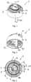
- the Figures 1 to 3 show the assembled dosing device 1 from different views.
- the metering device 1 comprises a cap 2 which can be attached to a container (not shown) and comprises an internal thread 2p, a control chamber 2a and an optional ventilation pipe 2m, the cap 2 or the metering device 1 having a longitudinal axis L which runs concentrically with respect to the internal thread 2p.
- the metering device 1 also includes an adjusting element 3 with a pouring opening 3b and a spout 3a.
- the adjusting element 3 is rotatably mounted in the cap 2 and can be rotated back and forth in a direction of movement H with respect to the cap 2.
- the center of rotation of the adjusting element 3 coincides with the longitudinal axis L.
- the center of rotation could be
- the adjusting element 3 can also be arranged eccentrically with respect to the longitudinal axis L.
- the adjusting element 3 also includes a pointer 3d, so that the position of the mutual rotation of the adjusting element 3 and cap 2 can be easily recognized visually.
- a scale 2o is arranged on the cap 2, for example a number scale, along which the pointer 3d is movably arranged, so that the pointer 3d can, for example, be moved reproducibly to the same location.
- the amount of dose delivered is set via the position of the pointer 3d.
- the closing part 4 located within the control chamber 2a can also be seen.
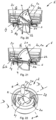
- FIG. 4 shows a longitudinal section through the metering device 1.
- Figure 4 shows the cap 2 with the control chamber 2a, the internal thread 2p, and the ventilation pipe 2m with ventilation inlet opening 21 and ventilation outlet opening 2n.
- the adjusting element 3 includes the spout 3a and the pouring opening 3b, and also includes a ventilation opening 3g extending in the circumferential direction H with respect to the longitudinal axis L, which is arranged with respect to the ventilation inlet opening 21 in such a way that the ventilation inlet opening 21 provides a fluid-conducting connection in every rotational position of the adjusting element 3 to the ambient air, in order to thereby exchange ambient air with the interior of the container via the ventilation pipe 2m and the ventilation outlet opening 2n.
- the closing part 4 is pivotally mounted on the cap 2 and is located in Figure 4 in a starting position in which the pouring opening 3b is completely open and is located in Figure 5 in an end position in which the pouring opening 3b is closed by the closing part 4 adjacent to it.
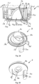
- the Figures 6 to 9 show the same cap 2 from different views.
- the cap 2 comprises an end wall 2ae, a control chamber 2a, which is delimited within the cap 2 by a first boundary wall 2b, a second boundary wall 2c and a first and a second side wall 2d, 2e, whereas the control chamber 2a is on the end face of the cap 2 is open.
- the cap 2 preferably also comprises two mutually spaced pivot bearings 2f, in which the bearing part of the closing part 4 is rotatably mounted.
- the pivot bearings 2f are preferably embedded in the end wall 2ae.
- the first boundary wall 2b is designed to run flat, whereas the second boundary wall 2c runs concentrically with respect to the axis S defined by the pivot bearings 2f.
- the first and second side walls 2d, 2e are designed to run parallel to one another.
- the control chamber 2a comprises a control chamber base 2s in which, with the cap 2 upright, preferably at the lowest point, a first exchange opening 2i is arranged, which forms a fluid-conducting connection from the supply space 2v to the interior of the control chamber 2a.
- the control chamber 2a advantageously also includes a second exchange opening 2h arranged in the first boundary wall 2b, which also forms a fluid-conducting connection to the interior of the control chamber 2a.
- the second boundary wall 2c subsequently faces that of the control chamber base 2s End section has a control chamber inlet opening 2g.
- the cap 2 preferably comprises on its end face a circular first guide part 2q, which protrudes over the end face and which is preferably arranged symmetrically to the longitudinal axis L, and which guides the adjusting element 3 and encloses it on the outside in the circumferential direction, so that it can be rotated about the longitudinal axis L in the Cap 2 is stored.
- the first exchange opening (2i), the control chamber inlet opening (2g) and the pouring opening (3b) are as shown in particular Figure 7 visible, arranged one after the other in the direction of the longitudinal axis (L).
- the Figures 10 to 12 show the adjusting element 3 from different views.
- the adjusting element 3 comprises a circular second guide part 3e, which can be inserted into the first guide part 2q of the cap 2 so that it is held in the cap 2.
- the adjusting element 3 includes the pouring opening 3b, the spout 3a, a beak 3c and the pointer 3d.
- the adjusting element 3 also includes the ventilation opening 3g, an adjusting element closure 3f and a stop surface 3h.
- the adjusting element closure 3f is part of the adjusting element 3, so that it can also be rotated about the longitudinal axis L when the adjusting element 3 is inserted into the cap 2.
- Figure 6 shows a side space 2k, wherein the adjusting element closure 3f is rotatably arranged in the adjusting element 3 in such a way that it cannot, partially or completely cover the control inlet opening 2g and can therefore close it.
- the adjusting element 3 can be rotated about the longitudinal axis L, so that the adjusting element closure 3f can be moved into the side space 2k and comes to rest at least partially or completely in the side space 2k, so that the control inlet opening 2g either only partially passes through the adjusting element closure 3f is covered or fully open.
- Figure 7 the opening of the side space 2k is shown in a front view, with the adjoining control chamber inlet opening 2g also being visible.
- Figure 7 also shows a hint of a container 5 comprising a container neck 5a, to which the cap 2 and thus the entire dosing device 1 is attached.
- the cap 2 comprises a feed space 2v, through which the liquid in the container 5 flows into the cap 2, the feed space 2v being separated from the pouring opening 3b of the adjusting element 3 by the control chamber 2a, the control chamber 2a having passage openings, in particular the first exchange opening 2i and the control chamber inlet opening 2g to supply the liquid in the container 5 to the pouring opening 3b in a controlled manner.
- the cap 2 preferably comprises a joint part 2r, to which a pivoting cover cap (not shown) can be attached in order to cover or close the end face of the metering device 1 by the cover cap after use.
- the spout is 3a, such as in Figure 1 shown, arranged on a side facing away from the joint part 2r, so that the container 5 collapses or rotates during dosing and pouring is that the spout 3a is lowered downwards, and the joint part 2r and the cover cap attached to it are lifted up so that the cover cap does not hinder pouring.
- Figure 8 shows, with the pouring line F, a preferred pouring direction or pivoting direction in which the dosing device 1 can be pivoted or tilted.
- the two pivot bearings 2f define a pivot axis S, around which the in the Figures 13 and 14 Closing part 4 shown is pivotally mounted.
- the pivot axis S points, as in Figure 8 shown, an angle ⁇ with respect to the pouring line F. This angle is preferably in a range between 0° and 90°, preferably between 5° and 75°, and particularly preferably between 5° and 30°.
- the dosing device is in a dry state when dosing for the first time, and the dosing device therefore releases too small an amount of the flowable substance due to the force of gravity
- the angle ⁇ particularly preferably has a value in the range between 5 ° and 30 °, depending, for example, on the viscosity of the liquid.
- the torque force acting on the closing part 4 can be influenced by an appropriate choice of the angle ⁇ , the angle ⁇ preferably being chosen such that the closing part 4 is in a dry state when pouring for the first time, in which the closing part 4 is initially still in a dry state , not pivoted too quickly, and in particular not pivoted independently of the flowable substance flowing into the partial control chamber 2u.
- Closing part 4 shown comprises a pivoting part 4a and a shaft 4c attached thereto, so that the pivoting part 4a is rotatably mounted in the pivot bearings 2f of the cap 2 via the shaft 4c about the pivot axis S.
- the closing part 4 also includes a closure part 4b, a first long side 4d, a second long side 4e, an end face 4f, a support part 4h, an extension 4i and optionally a label 4g.
- the closing part 4 is preferably designed in one piece, so that the shaft 4c is part of the closing part 4.
- FIGs 15 and 16 show a front view of the control chamber inlet opening 2g, with this in Figure 15 forms a completely open passage opening.
- Figure 16 By turning the adjusting element 3 or by moving the adjusting element closure 3f, which is firmly connected to the adjusting element, in the direction of movement H, the control chamber inlet opening 2g is partially covered, so that a smaller one Passage opening is formed through which a fluid or the flowable substance can flow.
- the adjusting element 3 is rotatably mounted in the cap 2, so that the size of the passage opening can be adjusted depending on the desired dosage quantity.
- Figure 17 shows a longitudinal section of the metering device 1 along the section line CC a completely open passage opening, in which the control chamber inlet opening 2g, as in Figure 15 shown, is not covered by the adjusting element closure 3f, so that in Figure 17 only the front side of the adjusting element closure 3f is visible, as well as the uncovered control chamber inlet opening 2g.
- Figure 18 shows a further longitudinal section through the metering device 1, in which the adjusting element 3 and its adjusting element closure 3f as in Figure 16 shown is twisted so that, as in Figure 18 shown, the adjusting element closure 3f shown in section covers the control chamber inlet opening 2g at the point of the cut.
- the amount of flowable substance to be dispensed by the metering device 1 can be adjusted by turning the adjusting element 3 in order to thereby adjust the area of the passage opening available for the flowable substance at the control chamber inlet opening 2g.
- the optional first step is carried out only once.
- the adjusting element 3 remains in the in Figure 17 basic position shown.
- the container 5 with the dosing device 1 attached to it is rotated or overturned about a horizontal axis, so that the dosing device 1 is aligned downwards and is rotated, for example, through an angle of 180 °, as in the Figures 19 to 21 shown.
- the container is not elastically deformable, or if no pressure is exerted on the elastically deformable container from the outside, it is necessary to pour the container 5 with the dosing device 1 attached to it, starting from the vertical, in Figures 17 and 18 to rotate the arrangement shown by an angular range between 90 ° and 270 ° so that the metering device 1 is aligned at least horizontally, and preferably aligned downwards.
- the ones in the Figures 19 to 21 The position shown is particularly advantageous when there is only a small remaining amount of the flowable substance or liquid G in the container 5.
- a metered amount of liquid G is now dispensed as in the Figures 19 to 21 shown.
- the closing part 4 which is arranged in the control chamber 2a and can be pivoted about the pivot axis S, divides the interior of the control chamber 2a into a flow chamber 2t and a partial control chamber 2u, the liquid G forming a first partial liquid flow G1, which is fed to the flow chamber 2t via the control chamber inlet opening 2g, wherein the liquid G forms a second partial liquid stream G2, which is fed to the partial control chamber 2u at least via the first exchange opening 2i.
- the first partial liquid flow G1 flows into the pouring opening 3b and is thereby discharged to the outside by the metering device 1.
- the second partial liquid flow G2 flows, starting from the feed space 2v, via the first exchange opening 2i into the partial control chamber 2u and accumulates there, with the inflowing second partial liquid flow G2 causing the amount of liquid located in the partial control chamber 2u to accumulate and thus continuously increase , and the closing part 4 as a result, as in Figure 20 shown, is increasingly pivoted towards the spout 3a.
- the second liquid partial flow G2 flowing into the partial control chamber 2u increases the volume of the partial control chamber 2u, so that the closing part 4 undergoes a pivoting movement until it rests on the stop surface 3h of the pouring opening 3b and the pouring opening 3b is thereby closed by the closing part 4, so that a further output of the first partial liquid stream G1 is prevented and the flow of the first partial liquid stream G1 is thus interrupted.
- the closing part 4, which pivots within the control chamber 2a, moves increasingly towards the pouring opening 3b during pouring, so that the pouring opening 3b is ultimately closed by the closing part 4 from the side of the control chamber 2a.
- the pouring opening 3b is closed with a time delay by the closing part 4, so that the total amount of liquid dispensed by the dosing device 1 during a dosing process is influenced, on the one hand, by the length of time up to which the pouring opening 3b is closed by the closing part 4 is closed, and on the other hand by the amount of liquid which flows outwards via the control chamber inlet opening 2g and subsequently via the pouring opening 3b per unit of time and is dispensed by the metering device 1.
- the free area of the control chamber inlet opening 2g can be adjusted by moving the adjusting element closure 3f, and thus the amount of liquid dispensed during a dosing process.
- the length of time up to which the pouring opening 3b is closed by the closing part 4 depends on several factors, in particular on the size of the first exchange opening 2i and the viscosity of the liquid G. It can be, as in the Figures 19 to 21 shown, prove to be advantageous to provide at least one further second exchange opening 2h in the control chamber 2a, through which an additional partial flow G2 of the liquid G can flow into the partial control chamber 2u, so that the second partial liquid flow G2 composed of several partial streams, one partial stream per opening between liquid G and partial control chamber 2u.
- the container with the dosing device 1 attached to it is erected again, so that the dosing device 1, for example, the in Figure 1 shown, vertically upwards position.
- the locking part 4 is still in the in Figure 21 position shown.
- the liquid located in the partial control chamber 2u flows back into the feed space 2v via the first exchange opening 2i and/or the second exchange opening 2h, so that the partial control chamber 2u is increasingly reduced in size and the flow chamber 2t is thereby enlarged until the entire liquid in the partial control chamber 2u has flowed out, and the closing part 4 is in turn in the in Figure 17 shown starting position.
- the metering device 1 is then ready to dispense a further metered amount of liquid by the container 5 with the metering device 1 attached to it being ready to be overturned again.
- FIG 22 shows a perspective view and Figure 23 a longitudinal section along the line DD of a further embodiment of a cap 2.
- Cap 2 shown includes the one in the Figures 22 and 23
- Cap 2 shown has a hollow body 2j, which in particular comprises a hollow body outer wall 2w and a hollow body end face 2x, which are arranged such that a first collecting area 2y and a second collecting area 2z are formed in the cap 2.
- This hollow body 2j or the first and second collecting areas 2y, 2z formed thereby ensures that the function of the metering device is still guaranteed even if there is a small residual amount of liquid in the container 5.
- the container 5 is shown indicated.
- the arrangement of the hollow body 2j has the result that the feed space 2v of the cap 2 is significantly reduced, or that the liquid in the container essentially accumulates in the first and second collection areas 2y, 2z, so that the amount of liquid dispensed can be metered even with a small remaining amount of liquid is possible in that there is still enough liquid available, which can flow into the flow chamber 2t, not shown, of the control chamber 2a via the first exchange opening 2i and / or the second exchange opening 2h, and which can flow via the control chamber inlet opening 2g and the adjusting element, not shown 3 can drain with pouring opening 3b.
- the exemplary embodiments shown show the control chamber 2 in a possible embodiment.
- the control chamber 2 and the closing part 4 adapted to the shape of the control chamber 2a can be designed in a variety of shapes, such that the closing part 4 is rotatably mounted in the cap 2 and the interior of the control chamber 2 into a flow chamber 2t and a partial control chamber 2u divided. So could the first and second side walls 2d, 2e, for example, may not be flat, but rather bulbous, running in the direction of rotation of the pivot axis S.
- the end face 4f could, for example, be angular, jagged, or section-wide star-shaped, with the second boundary wall 2c being designed opposite to the end face 4f, so that only a small gap is formed between the end face 4f and the boundary wall 2c.
- FIGS 24 to 26 show a further exemplary embodiment of an adjusting element 3, which, in contrast to that in the Figures 10 to 12 Adjusting element 3 shown does not have an elongated, circumferentially extending ventilation opening 3g, but has a ventilation pipe 3m with a second ventilation inlet opening 31 and a second ventilation outlet opening 3n.
- the adjusting element 3 according to Figures 24 to 26 is particularly advantageously suitable for combination with the one in the Figures 22 , 23 and 27 cap 2 shown.
- Figure 27 shows an adjusting element 3 rotatably attached to the cap 2, the adjusting element 3 not having a pointer 3d, but otherwise as in the Figures 24 to 26 is designed as shown.
- the adjusting element 3 can be rotated, for example, by twisting the spout 3a with your fingers.
- the spout 3a could also be designed to protrude further, be longer and, for example, tubular in the direction of the longitudinal axis L in order to form an even larger area for actuation by the fingers.
- the ventilation pipe 3m is arranged completely within the cavity 2j, so that it runs in the longitudinal direction L within the cavity 2j.
- the adjusting element 3 is rotatably mounted about the longitudinal axis L in the first guide part 2q of the cap 2 via the second guide part 3e, whereby the ventilation pipe 3m can also be moved within the cavity 2j in the circumferential direction H.
- the arrangement shown has the particular advantage that the flowable substance G 3 flowing back during pouring through the ventilation outlet opening 2n and the ventilation pipe 2m is collected at the bottom in the cavity 2j as retained substance G 4 , and is therefore not dispensed via the ventilation pipe 3m.
- the level of the retained substance G 4 does not rise to the level of the second ventilation outlet opening 3n, outflow via the ventilation pipe 3m can be prevented. It can thus be prevented that a flowable substance is dispensed from the container 5 or from the feed space 2v in an uncontrolled manner by the dosing device 1 during dosing, which significantly increases the accuracy of the repeatedly dispensed amount of flowable substance.
- the amount of substance G 3 that may flow back can be influenced by the size of the ventilation outlet opening 2n and also by the length of time during which the container is in the upturned position. These parameters are preferably chosen such that the level of the substance G 4 does not rise to the second ventilation outlet opening 3n during pouring. As soon as the container is swiveled back into the upright position, the retained substance G 4 , if present at all, flows over the ventilation pipe 2m and the Ventilation outlet opening 2n back into the feed space 2v or into the interior of the container 5.
- FIGS. 28 and 29 show a further embodiment of a cap 2, which is designed similarly to that in the Figures 7 and 9 Cap 2 shown, which is why the differences to the one in the are essentially explained below Figures 7 and 9 Cap 2 shown can be explained.
- a guide channel 2aa having a connection opening 2af is arranged in the area of the first exchange opening 2i, wherein the guide channel 2aa conductively connects the first exchange opening 2i and the connection opening 2af to one another, that is to say conductively connects them for a flowable substance, so that the flowable substance can flow back and forth via the guide channel 2aa between the feed space 2v and the interior 2ad of the control chamber 2a.
- the guide channel 2aa advantageously runs as shown in Figure 29 shown, parallel to the longitudinal axis L, and preferably straight. However, the guide channel 2aa can also run at an angle with respect to the longitudinal axis L and/or can have a curved course.
- the cap 2 comprises a threaded cap 2ab with an internal thread 2p, which can be screwed onto a container.
- the threaded cap 2ab has a height H2 in the direction of the longitudinal axis L.
- the length of the guide channel 2aa is preferably at least 1/10 of the height H2, the length in particular being in a range from 1/3 to 2/3 of the height H2.
- the guide channel 2aa is preferably tubular, particularly preferably as in the Figures 28 and 29 shown as a round tube.
- the guide channel 2aa could also have other cross sections, for example square, rectangular or oval.
- the inner diameter of the guide channel 2aa is preferably between 1 mm and 5 mm.
- the flowable substance has an advantageous flow behavior, preferably a substantially laminar flow.
- the guide channel 2aa has the advantage that the exchange of the flowable substance between the feed space 2v and the control chamber 2a is reproducible.
- the guide channel 2aa therefore has the particular advantage that the flowable substance is reproducibly fed from the feed space 2v into the control chamber 2a in a fluid-reproducible manner, which has the advantage that the partial control chamber 2u is reproducibly filled, and thus the cap 2 during a pouring process dispensed amount of flowable substance is preferably particularly precisely reproducible, so that successive pouring processes of flowable substance have the same or essentially the same amount.
- the guide channel 2aa is particularly advantageously designed as a round tube, particularly advantageously running in the direction of the longitudinal axis L.
- the guide channel 2aa thus preferably increases the reproducibility of the respectively poured delivery quantity of the flowable substance located in the container 5, for example a fluid which is released during successive pouring processes.
- the embodiment shown also has the advantage that the amount of flowable substance poured out during a pouring process also preferably corresponds exactly to the intended delivery amount in a reproducible manner if the Longitudinal axis L of the cap 2 does not run parallel to the gravitational force or the vertical during pouring, but is held obliquely and has an angle with respect to the gravitational force, for example an angle in the range between 0 and 45 ° between the gravitational force or the vertical and the longitudinal axis L.
- the cap 2 each comprises a threaded cap 2ab with an internal thread 2p and an additional outer cap 2ac.
- the threaded cap 2ab and the outer cap 2ac could also be designed together and thus in one piece.
- the dosing device 1 could be dispensed with the ventilation pipe 2m and/or the ventilation pipe 3m.
- the dosing device 1 could also be designed in such a way that it only delivers a fixed dosage amount of liquid.
- the adjusting element 3 could be connected to the metering device 1 in such a way that the adjusting element 3 is not rotatable, but is fixedly arranged with respect to the metering device 1, so that the free passage area of the control chamber inlet opening 2g is fixed by the non-rotatably arranged adjusting element closure 3f.
- the adjusting element 3 could, for example, be arranged in a rotationally fixed manner in the cap 2 with the aid of a cam, not shown, which interacts with the cap 2.
- the limiting element 3f could be dispensed with in the adjusting element 3, in that the control chamber inlet opening 3g has a fixed, free passage area, which is adapted according to the intended dosage quantity to be specified.
- the adjusting element 3 would only have the purpose of covering the end face of the cap 2 and forming the pouring opening 3b with a spout 3a, and if necessary also forming the optional ventilation opening 3g or the optional ventilation pipe 3m with ventilation inlet opening 21 and ventilation outlet opening 2n.
- the closing part 4 as in Figure 14 shown, a preferably thorn-shaped extension 4i, which, depending on the position of the closing part 4, engages in the second exchange opening 2h.
- a preferably thorn-shaped extension 4i which, depending on the position of the closing part 4, engages in the second exchange opening 2h.
- the task of the extension 4i is to ensure that no such bubble forms or, if such a bubble has formed, that it is destroyed by the extension 4i penetrating into the second exchange opening 2h.
- the extension 4i can be designed in a variety of shapes, preferably pointed.
- the adjusting element 3 shown in the figures is shown in the illustrated embodiments as a rotating part, which is rotated in the circumferential direction of a longitudinal axis.
- the adjusting element 3 could also be designed as a rotating part that is rotatably mounted about an axis deviating from the longitudinal axis.
- the adjusting element 3 could also be designed to be linearly movable, so that it is mounted in a linearly movable manner in the cap 2, whereby this linearly movable adjusting element closure 3f can adjustably cover the control chamber inlet opening 2g, and thereby determines the opening area of the control chamber inlet opening 2g available for pouring.
Landscapes
- Physics & Mathematics (AREA)
- Fluid Mechanics (AREA)
- General Physics & Mathematics (AREA)
- Containers And Packaging Bodies Having A Special Means To Remove Contents (AREA)
- Closures For Containers (AREA)
- Feeding, Discharge, Calcimining, Fusing, And Gas-Generation Devices (AREA)
Description
- Die Erfindung betrifft eine Dosiervorrichtung sowie ein Verfahren zur Abgabe einer fliessfähigen Substanz.
- Eine Dosiervorrichtung zur Abgabe einer kontrollierten Flüssigkeitsmenge ist beispielsweise aus dem Dokument
WO2018/080966A1 bekannt. Diese Dosiervorrichtung wird zum Ausgeben einer definierten Flüssigkeitsmenge aus einem Behälter verwendet, wobei der Behälter einen Stutzen aufweist, mit welchem die Dosiervorrichtung durch Aufschrauben verbindbar ist. Diese Dosiervorrichtung weist die Nachteile auf, dass deren Herstellung relativ aufwändig und somit relativ teuer ist, und dass die Dosierung unter gewissen Umständen nicht zufriedenstellend reproduzierbar erfolgt. Zudem wird die Dosis nur dann abgegeben, wenn der Behälter zusammengedrückt wird. Das DokumentUS2331659 offenbart eine weitere Dosiervorrichtung. Diese Dosiervorrichtung weist unter anderem die Nachteile auf, dass die abgegebene Flüssigkeitsmenge fest vorgegeben ist und nicht verändert werden kann, und dass die Dosiervorrichtung einen Ventildeckel aufweist, der nach erfolgter Ausgabe der Flüssigkeitsmenge von Hand verschlossen werden muss, sodass die Hand beziehungsweise die Finger beim Schliessen durch allenfalls vorhandene Rückstände der Flüssigkeit verunreinigt werden. - Aufgabe der Erfindung ist es somit eine vorteilhaftere Dosiervorrichtung zur Abgabe einer kontrollierten Menge einer fliessfähigen Substanz auszugestalten, die insbesondere verbesserte Dosiereigenschaften aufweist. Zudem ist es Aufgabe der Erfindung ein vorteilhafteres Verfahren zur Abgabe einer kontrollierten Menge einer fliessfähigen Substanz auszugestalten.
- Diese Aufgabe wird gelöst mit einer Dosiervorrichtung aufweisend die Merkmale von Anspruch 1. Die abhängigen Ansprüche 2 bis 18 betreffen weitere vorteilhafte Ausgestaltungen. Die Aufgabe wird weiter gelöst mit einem Verfahren aufweisend die Merkmale von Anspruch 19. Die abhängigen Ansprüche 20 bis 22 betreffen weitere vorteilhafte Verfahrensschritt.
- Die Aufgabe wird insbesondere gelöst mit einer Dosiervorrichtung zur Abgabe einer fliessfähigen Substanz, umfassend eine Kappe aufweisend einen Zuführraum, der Fluid leitend mit einem Behälter oder einer Zufuhr verbindbar ist, sowie umfassend eine Steuerkammer, ein Schliessteil und eine Ausgussöffnung, wobei die Steuerkammer einen Innenraum ausbildet, in welchem das Schliessteil angeordnet ist, wobei das Schliessteil um eine Schwenkachse drehbar gelagert ist, wobei das Schliessteil den Innenraum der Steuerkammer in eine Durchflusskammer und eine Teilsteuerkammer unterteilt, wobei die Durchflusskammer die fliessfähige Substanz leitend mit der Ausgussöffnung verbunden ist, wobei die Steuerkammer eine Austauschöffnung aufweist, über welche der Zuführraum die fliessfähige Substanz leitend mit der Teilsteuerkammer verbunden ist, und wobei die Steuerkammer eine Steuerkammereinlassöffnung aufweist, über welche der Zuführraum, abhängig von der Stellung des Schliessteils, entweder mit der Durchflusskammer oder mit der Teilsteuerkammer die fliessfähige Substanz leitend verbunden ist, und wobei das Schliessteil bis zu einer Stellung drehbar ist, bei welcher die Ausgussöffnung durch das Schliessteil verschlossen ist, was ein weiteres Austreten der fliessfähigen Substanz aus der Ausgussöffnung verhindert.
- Vorzugsweise sind die Austauschöffnung, die Steuerkammereinlassöffnung und die Ausgussöffnung in Verlaufsrichtung der Längsachse nacheinander folgend angeordnet.
- Die Aufgabe wird weiter insbesondere gelöst mit einem Verfahren zur Abgabe einer fliessfähigen Substanz aus einem Behälter oder einer Zufuhr, wobei eine Dosiervorrichtung, umfassend eine Kappe und eine Steuerkammer, mit dem Behälter oder der Zufuhr verbunden wird, wobei ein schwenkbares Schliessteil in der Steuerkammer angeordnet ist, welches den Innenraum der Steuerkammer in eine Durchflusskammer und eine Teilsteuerkammer unterteilt, indem die zugeführte, fliessfähige Substanz während dem Ausgeben über eine Steuerkammereinlassöffnung der Durchflusskammer zugeführt wird und anschliessend zur Ausgabe einer Ausgussöffnung zugeführt wird, und indem ein Teil der sich im Behälter oder der Zufuhr befindlichen fliessfähigen Substanz, insbesondere eine Flüssigkeit, der Teilsteuerkammer zugeführt wird, sodass das mit der fliessfähigen Substanz gefüllte Volumen der Teilsteuerkammer zunimmt und dadurch das Schliessteil so lange geschwenkt wird, bis dieses an der Ausgussöffnung anliegt, und dadurch die Ausgabe der fliessfähigen Substanz unterbrochen wird.
- Die erfindungsgemässe Dosiervorrichtung ist zur Abgabe einer fliessfähigen Substanz geeignet, wobei als fliessfähige Substanz bevorzugt eine Flüssigkeit oder ein Gel verwendet wird, wobei die fliessfähige Substanz auch eine Flüssigkeit enthaltend Feststoffe sein kann, oder auch eine rieselfähige Substanz enthaltend ausschliesslich Feststoffe, insbesondere eine rieselfähige gekörnte Substanz. Die erfindungsgemässe Dosiervorrichtung ist insbesondere zur Abgabe einer fliessfähigen Substanz im Haushalt geeignet, beispielweise zur dosierten Abgabe von Wasser, flüssigem Waschmittel, Weichspüler, Geschirrspülmittel, Putzmittel, Getränken, Ölen, Kondensmilch, Rahm oder Körperpflegeprodukten wie Gesichtscreme.
- Die erfindungsgemässe Dosiervorrichtung wird vorzugsweise auf einen Stutzen eines Behälters aufgesetzt, beispielsweise durch Aufschrauben oder Aufprellen, wobei der Behälter zur dosierten Abgabe der fliessfähigen Substanz vorzugsweise gestürzt wird, sodass die sich im Behälter befindliche fliessfähige Substanz über die Dosiervorrichtung in einer dosierten Portion ausgegeben wird. Zur Abgabe einer weiteren dosierten Portion wird der Behälter vorzugsweise vollständig aufgerichtet, damit die Dosiervorrichtung wieder eine Ausgangslage einnehmen kann und das schwenkbare Schliessteil wieder in eine Ausgangslage bewegt wird, wobei der Behälter danach wieder gestürzt wird, und danach eine weitere dosierte Portion der fliessfähigen Substanz ausgegeben wird. Der Behälter ist vorzugsweise als ein Kunststoffbehälter ausgestaltet, wobei dieser auch als starrer Behälter oder als elastisch verformbarer Behälter ausgestaltet sein kann. In einem vorteilhaften Verfahrensschritt wird der elastisch verformbare Behälter kurz vor der Ausgabe der fliessfähigen Substanz oder während der Ausgabe der fliessfähigen Substanz zusammengedrückt, sodass die fliessfähige Substanz im Behälter unter Druck steht, und die fliessfähige Substanz dadurch beispielsweise schneller ausgegeben wird, oder die fliessfähige Substanz bei unterschiedlichen Stellungen des Behälters ausgegeben werden kann. Der Behälter kann auch schlauchartig ausgestaltet sein, wobei die Dosiervorrichtung mit dem schlauchartigen Behälter verbunden ist. Die Dosiervorrichtung kann auch mit einer Zufuhr, beispielsweise einem Schlauch, verbunden sein, über welche eine fliessfähige Substanz wie eine Flüssigkeit zugeleitet wird, wobei der Schlauch vorzugsweise mit einem Tankbehälter verbunden ist. Eine dosierte Abgabe der über die Zufuhr zugeleiteten fliessfähigen Substanz erfolgt ähnlich wie mit einem Behälter, indem die mit der Zufuhr verbundene-Dosiervorrichtung gestürzt oder unter Druck gesetzt wird, sodass die zugeleitete fliessfähige Substanz über die Dosiervorrichtung in einer dosierten Portion ausgegeben wird. Daraufhin wird die Dosiervorrichtung vorzugsweise vollständig aufgerichtet, damit die Dosiervorrichtung, insbesondere das schwenkbare Schliessteil, wieder eine Ausgangslage einnehmen kann, wobei die Dosiervorrichtung danach wieder gestürzt wird, und danach eine weitere dosierte Portion der fliessfähigen Substanz ausgegeben wird.
- Die erfindungsgemässe Dosiervorrichtung weist den Vorteil auf, dass diese in der einfachsten Ausführungsform aus nur drei Teilkomponenten besteht, nämlich einer Kappe, einem Einstell- oder Abdeckelement sowie einem Schliessteil, welche zusammengefügt die Dosiervorrichtung ergeben. Diese drei Teilkomponenten werden vorzugsweise durch Spritzgiessen hergestellt, wobei die derart hergestellten Spritzgussteile als geometrisch einfache Formteile ausgestaltet sind, sodass sowohl die Herstellung der zum Spritzen erforderlichen Werkzeuge als auch die Herstellung der Spritzgussteile sehr kostengünstig erfolgen kann. Die erfindungsgemässe Dosiervorrichtung weist den weiteren Vorteil auf, dass die drei Teilkomponenten auf sehr einfache Weise und vorzugsweise automatisiert zur erfindungsgemässen Dosiervorrichtung zusammenbaubar sind, sodass diese Dosiervorrichtung sehr kostengünstig herstellbar ist. Zudem ist zu deren Herstellung eine geringe Menge Kunststoff erforderlich, was die Vorteile ergibt, dass die erforderliche Kunststoffmenge kostengünstig ist, und dass nach dem Gebrauch der Dosiervorrichtung eine geringere Menge Abfall entsteht. Der äusserst einfache Aufbau der erfindungsgemässen Dosiervorrichtung ermöglicht es diese langfristig und mehrfach zu verwenden, da die Dosiervorrichtung problemlos auseinandergebaut, gereinigt und wieder zusammengebaut werden kann und deren Funktion somit langfristig gewährleistet ist. Diese Mehrfachverwendbarkeit der Dosiervorrichtung wird insbesondere von umweltbewussten Kunden als ein Mehrwert erachtet, da ein Behälter mit einem einfachen Verschluss gekauft werden kann und der Verschluss nach dem Öffnen des Behälters durch die Dosiervorrichtung ausgetauscht werden kann.
- Die erfindungsgemässe Dosiervorrichtung weist zudem den Vorteil auf, dass die Dosierung wiederholbar zuverlässig erfolgt. Die im Dokument
WO2018/080966A1 offenbarte Anordnung umfasst einen linear beweglich angeordneten Kolben. Da dieser frei im Zylinder beweglich ist ergeben sich die Nachteile, dass die Bewegung des Kolbens behindert werden kann, beispielsweise indem sich der Kolben im Zylinder verkantet, indem eine sich im Kolben befindliche Flüssigkeit die Bewegung behindert, oder indem an der Kolbenwand angelagerte Rückstände wie eine eingetrocknete Flüssigkeit eine Bewegung behindern oder verhindern. Die erfindungsgemässe Dosiervorrichtung weist den Vorteil auf, dass das bewegliche Schliessteil um eine Achse drehbar gelagert ist, und vorzugsweise in der Kappe gelagert ist, sodass das Schliessteil bezüglich der Kappe eine definierte Lage aufweist. Besonders vorteilhaft ist eine Ausgestaltung, bei welcher die Achse ein Teil des Schliessteils ist und das Lager ein Teil der Kappe ist, sodass das Schliessteil genau definiert bezüglich der Kappe und der sich in der Kappe befindlichen Steuerkammer angeordnet ist, sodass das Schliessteil entlang der gesamten möglichen Schwenkbewegung eine definierte Lage bezüglich den Begrenzungswänden der Steuerkammer aufweist. Vorzugsweise ist die Achse derart in der Kappe gelagert, dass die Achse nur ein sehr geringes Spiel aufweist, insbesondere in Verlaufsrichtung der Achse, um dadurch einerseits eine Berührung des Schliessteils mit den seitlichen Begrenzungswänden der Steuerkammer zu vermeiden, und um andererseits sicherzustellen, dass die Spaltbreite zwischen Schliessteil und Begrenzungswänden gering bleibt, und beispielsweise im Bereich zwischen 0,2 bis 1 mm liegt. Die im DokumentWO2018/080966A1 offenbarte Anordnung weist zudem den Nachteil auf, dass eine Dosis nur dann abgegeben wird, wenn der Behälter zusammengedrückt wird. Die erfindungsgemässe Dosiervorrichtung kann auch ohne Zusammendrücken eines Behälters eine Dosis abgeben. Um dies zu ermöglichen weist die erfindungsgemässe Dosiervorrichtung vorteilhafterweise ein Belüftungsrohr auf, welches vorzugsweise einen Luftaustausch zwischen dem Behälteraussenraum und dem Behälterinnenraum ermöglicht. - Die im Dokument
WO 2018/080966A1 offenbarte Anordnung weist zudem den Nachteil auf, dass sich der Kolben beim erstmaligen Dosieren in einem trockenen Zustand befindet, da dieser vor der ersten Ausgabe noch nie mit der auszugebenden fliessfähigen Substanz in Kontakt gelangt ist. Dies hat zur Folge, dass die erste von der Dosiervorrichtung abgegebene Dosis zu klein ausfallen kann, da der Kolben in trockenem Zustand beim Stürzen des Behälters durch die einwirkende Schwerkraft bewegt werden kann und sich dieser deshalb unmittelbar nach dem Stürzen nicht mehr in der vorgesehenen Ausgangsposition befindet, was zur Folge hat, dass die dabei abgegebene Menge an fliessfähiger Substanz zu gering ausfällt. Diese offenbarte Anordnung weist somit eine reduzierte Genauigkeit beziehungsweise eine reduzierte Reproduzierbarkeit der abgegebenen Dosiermenge auf. - Die erfindungsgemässe Vorrichtung ist zur dosierten Abgabe von fliessfähigen Substanzen geeignet, insbesondere zur dosierten Abgabe von Flüssigkeiten wie beispielsweise Wasser, flüssiges Waschmittel, Weichspüler, Geschirrspülmittel, Putzmittel, Getränke, Öl, oder Kondensmilch. Die erfindungsgemässe Vorrichtung ist jedoch auch zur dosierten Abgabe von festen fliessfähigen Substanzen wie beispielsweise Granulate geeignet. Die erfindungsgemässe Vorrichtung ist somit beispielsweise zur Abgabe von Substanzen wie Pflanzenschutzmitteln oder Düngemitteln geeignet.
- Der hierin verwendete Begriff "Dosis" ist definiert als die gemessene Menge der fliessfähigen Substanz, nachfolgend als Flüssigkeit bezeichnet, die von der Dosiervorrichtung abgegeben wird. Die Dosis beginnt, wenn die Flüssigkeit zum ersten Mal aus der Ausgussöffnung austritt, und endet, wenn der aus der Ausgussöffnung ausfliessende Strom der Flüssigkeit zum Stillstand kommt. Das Flüssigkeitsvolumen, das jeweils dosiert wird, beträgt typischerweise 1 ml bis 200 ml, vorzugsweise 3 ml bis 50 ml, bevorzugter 10 ml bis 30 ml und noch bevorzugter 15 ml bis 30 ml.
- Die erfindungsgemässe Dosiervorrichtung ist zur Anwendung in Kombination mit starren Behältern als auch mit elastisch zusammendrückbaren Behältern geeignet, wobei unter «elastisch zusammendrückbaren» Behältern ein Behälter verstanden wird, der in seine ursprüngliche Form zurückkehrt, ohne eine dauerhafte Verformung zu erleiden, sobald der Druck nachlässt. Vorteilhafterweise erlaubt die erfindungsgemässe Dosiervorrichtung eine Dosismenge zu dosieren, die bezüglich einer vorgegebenen Soll-Dosis eine Abweichung von weniger als 10% aufweist, die in Abhängigkeit der Art der Flüssigkeit auch kleiner oder grösser sein kann.
- Die erfindungsgemässe Dosiervorrichtung eignet sich insbesondere für den Hausgebrauch oder den Haushalt, beispielsweise für Reinigungsmittel wie z.B. harte Oberflächenreinigungsmittel, flüssige Waschmittelzusammensetzungen oder andere Reinigungsmittel, wie Weichspüler und dergleichen. Weitere Anwendungsgebiete sind Dosiervorrichtungen für manuelle und maschinelle Geschirrspülmittel oder Haarpflegeprodukte, oder Getränke wie Sirupe, Spirituosen, Alkohole, flüssige Kaffeekonzentrate und dergleichen, oder Lebensmittelanwendungen wie Lebensmittelpasten und flüssige Lebensmittelzutaten.
- Die dosierte Flüssigkeit ist vorzugsweise eine Reinigungsmittelzusammensetzung. Die dosierte Flüssigkeit kann eine newtonsche Flüssigkeit oder eine Scherverdünnung sein. Unter Scherverdünnung ist gemeint, dass die genannte Flüssigkeit nicht-newtonisch ist und vorzugsweise eine Viskosität aufweist, die sich mit Änderungen der Scherrate ändert. Die Viskosität der Flüssigkeit kann von 1 bis 350mPa·s, vorzugsweise von 1 bis 300mPa·s, vorzugsweise von 1 bis 250 mPa·s, noch bevorzugter von 1 bis 220 mPa·s, noch bevorzugter von 1 bis 200mPa·s und am bevorzugtesten von 1 bis 150mPa·s (gemessen bei 20°C) betragen.
- Vorteilhafterweise umfasst die erfindungsgemässe Dosiervorrichtung ein Einstellelement, vorzugsweise ein Einstellelement, mit welchem die von der Dosiervorrichtung abgegebene Menge an fliessfähiger Substanz je nach Erfordernis einstellbar ist. Es kann sich jedoch auch als vorteilhaft erweisen die Dosiervorrichtung derart auszugestalten, dass diese nur eine fest vorgegebene Menge an fliessfähiger Substanz ausgibt, indem auf das einstellbare Einstellelement verzichtet wird.
- Die Erfindung wird nachfolgend an Hand mehrerer Ausführungsbeispiele beschrieben.
- Die zur Erläuterung der Ausführungsbeispiele verwendeten Zeichnungen zeigen:
- Fig. 1
- eine perspektivische Ansicht eines ersten Ausführungsbeispiels einer Dosiervorrichtung von oben;
- Fig. 2
- eine perspektivische Ansicht der Dosiervorrichtung von unten;
- Fig. 3
- eine Stirnansicht der Dosiervorrichtung von oben;
- Fig. 4
- eine perspektivische Ansicht der Dosiervorrichtung von oben, teilweise im Längsschnitt;
- Fig. 5
- eine weitere perspektivische Ansicht der Dosiervorrichtung von oben, teilweise im Längsschnitt;
- Fig. 6
- eine perspektivische Ansicht einer Kappe der Dosiervorrichtung von oben;
- Fig. 7
- einen Längsschnitt durch die Kappe gemäss
Fig. 6 entlang der Schnittlinie A-A; - Fig. 8
- eine Ansicht der Kappe gemäss
Fig. 6 von unten; - Fig. 9
- eine perspektivische Ansicht der Kappe gemäss
Fig. 6 von unten; - Fig. 10
- eine perspektivische Ansicht eines Einstellelements der Dosiervorrichtung von oben;
- Fig. 11
- einen Längsschnitt durch das Einstellelement gemäss
Fig. 10 entlang der Schnittlinie B-B; - Fig. 12
- eine perspektivische Ansicht des Einstellelements gemäss
Fig. 10 von unten; - Fig. 13
- eine perspektivische Ansicht eines Schliessteils von oben;
- Fig. 14
- eine perspektivische Ansicht des Schliessteils gemäss
Fig. 13 von unten; - Fig. 15
- eine Ansicht einer vollständig geöffneten Steuerkammereinlassöffnung der Kappe;
- Fig. 16
- eine Ansicht der nur teilweise geöffneten Steuerkammereinlassöffnung der Kappe;
- Fig. 17
- einen Längsschnitt durch die Dosiervorrichtung entlang der Schnittlinie C-C gemäss
Figur 3 mit vollständig geöffneter Steuerkammereinlassöffnung; - Fig. 18
- einen Längsschnitt durch die Dosiervorrichtung entlang der Schnittlinie C-C mit geschlossener Steuerkammereinlassöffnung;
- Fig. 19
- einen Längsschnitt durch die Dosiervorrichtung entlang der Schnittlinie C-C zu Beginn des Ausgiessens einer Flüssigkeit;
- Fig. 20
- einen Längsschnitt durch die Dosiervorrichtung entlang der Schnittlinie C-C während des Ausgiessens der Flüssigkeit;
- Fig. 21
- einen Längsschnitt durch die Dosiervorrichtung entlang der Schnittlinie C-C nach Abschluss des Ausgiessens der Flüssigkeit;
- Fig. 22
- eine perspektivische Ansicht der Unterseite eines weiteren Ausführungsbeispiels einer Kappe;
- Fig. 23
- einen Längsschnitt durch die Kappe gemäss
Figur 22 entlang der Schnittlinie D-D; - Fig. 24
- eine perspektivische Ansicht eines weiteren Ausführungsbeispiels eines Einstellelementes;
- Fig. 25
- eine perspektivische Ansicht des Einstellelements gemäss
Figur 24 von unten; - Fig. 26
- einen Längsschnitt durch das Einstellelement gemäss
Figur 24 ; - Fig. 27
- einen Längsschnitt durch die Kappe gemäss
Figur 22 entlang der Schnittlinie E-E; - Fig. 28
- eine perspektivische Ansicht eines weiteren Ausführungsbeispiels einer Dosiervorrichtung;
- Fig. 29
- einen Längsschnitt durch die Dosiervorrichtung gemäss
Fig. 28 . - Grundsätzlich sind in den Zeichnungen gleiche Teile mit gleichen Bezugszeichen versehen.
- Die
Figuren 1 bis 14 und17 bis 21 zeigen an Hand eines ersten Ausführungsbeispiels dieselbe Dosiervorrichtung 1 und deren Teile aus unterschiedlichen Perspektiven, mit unterschiedlichen Schnitten und bei unterschiedlichen Zuständen. DieFiguren 1 bis 3 zeigen die zusammengebaute Dosiervorrichtung 1 aus unterschiedlichen Ansichten. Die Dosiervorrichtung 1 umfasst eine an einem nicht dargestellten Behälter befestigbare Kappe 2 umfassend ein Innengewinde 2p, eine Steuerkammer 2a sowie ein optionales Belüftungsrohr 2m, wobei die Kappe 2 bzw. die Dosiervorrichtung 1 eine Längsachse L aufweist, welche konzentrisch bezüglich dem Innengewinde 2p verläuft. Die Dosiervorrichtung 1 umfasst zudem ein Einstellelement 3 mit einer Ausgussöffnung 3b und einem Ausguss 3a. Das Einstellelement 3 ist drehbar in der Kappe 2 gelagert und ist in einer Bewegungsrichtung H bezüglich der Kappe 2 hin- und her verdrehbar. Vorteilhafterweise fällt das Drehzentrum des Einstellelementes 3 mit der Längsachse L zusammen. In einer weiteren Ausführungsform könnte das Drehzentrum des Einstellelementes 3 jedoch auch exzentrisch bezüglich der Längsachse L angeordnet sein. In einer vorteilhaften Ausgestaltung umfasst das Einstellelement 3 zudem einen Zeiger 3d, sodass die Stellung der gegenseitigen Verdrehung von Einstellelement 3 und Kappe 2 optisch einfach erkennbar ist. Besonders bevorzugt ist an der Kappe 2 eine Skala 2o angeordnet, beispielsweise eine Zahlenskala, entlang welcher der Zeiger 3d beweglich angeordnet ist, sodass der Zeiger 3d beispielsweise reproduzierbar an dieselbe Stelle verschoben werden kann. Wie nachfolgend im Detail noch erläutert wird über die Stellung des Zeigers 3d die Menge der abgegebenen Dosis eingestellt. In der Draufsicht gemässFigur 3 ist zudem noch das sich innerhalb der Steuerkammer 2a befindliche Schliessteil 4 erkennbar. - Die
Figuren 4 und 5 zeigen einen Längsschnitt durch die Dosiervorrichtung 1.Figur 4 zeigt die Kappe 2 mit der Steuerkammer 2a, dem Innengewinde 2p, sowie dem Belüftungsrohr 2m mit Belüftungseintrittsöffnung 21 und Belüftungsaustrittsöffnung 2n. Das Einstellelement 3 umfasst den Ausguss 3a sowie die Ausgussöffnung 3b, und umfasst zudem eine bezüglich der Längsachse L in Umfangsrichtung H verlaufende Belüftungsöffnung 3g, welche derart bezüglich der Belüftungseintrittsöffnung 21 angeordnet ist, dass die Belüftungseintrittsöffnung 21 bei jeder Drehstellung des Einstellelementes 3 eine Fluid leitende Verbindung zur Umgebungsluft aufweist, um dadurch über das Belüftungsrohr 2m und die Belüftungsaustrittsöffnung 2n Umgebungsluft mit dem Innenraum des Behälters auszutauschen. Das Schliessteil 4 ist schwenkbar an der Kappe 2 gelagert, und befindet sich inFigur 4 in einer Ausgangsstellung, bei welcher die Ausgussöffnung 3b vollständig geöffnet ist, und befindet sich inFigur 5 in einer Endstellung, bei welcher die Ausgussöffnung 3b durch das daran anliegende Schliessteil 4 geschlossen ist. - Die
Figuren 6 bis 9 zeigen dieselbe Kappe 2 aus unterschiedlichen Ansichten. Die Kappe 2 umfasst eine Stirnwand 2ae, eine Steuerkammer 2a, welche innerhalb der Kappe 2 durch eine erste Begrenzungswand 2b, eine zweite Begrenzungswand 2c sowie eine erste und eine zweite Seitenwand 2d, 2e begrenzt ist, wogegen die Steuerkammer 2a an der Stirnseite der Kappe 2 offen ist. Die Kappe 2 umfasst vorzugsweise zudem zwei gegenseitig beabstandete Drehlager 2f, in welchen das Lagerteil des Schliessteils 4 drehbar gelagert ist. Die Drehlager 2f sind vorzugsweise in der Stirnwand 2ae eingelassen. Die erste Begrenzungswand 2b ist eben verlaufend ausgestaltet, wogegen die zweite Begrenzungswand 2c konzentrisch bezüglich der durch die Drehlager 2f definierten Achse S verläuft. Die erste und die zweite Seitenwand 2d, 2e sind gegenseitig parallel verlaufend ausgestaltet. Die Steuerkammer 2a umfasst eine Steuerkammerbasis 2s bei welcher, bei aufrechter Kappe 2 vorzugsweise an der untersten Stelle, eine erste Austauschöffnung 2i angeordnet ist, welche eine Fluid leitende Verbindung vom Zuführraum 2v zum Innenraum der Steuerkammer 2a ausbildet. Die Steuerkammer 2a umfasst vorteilhafterweise zudem eine in der ersten Begrenzungswand 2b angeordnete zweite Austauschöffnung 2h, welche ebenfalls eine Fluid leitende Verbindung zum Innenraum der Steuerkammer 2a ausbildet. Die zweite Begrenzungswand 2c weist nachfolgend dem der Steuerkammerbasis 2s gegenüber liegenden Endabschnitt eine Steuerkammereinlassöffnung 2g auf. Die Kappe 2 umfasst vorzugsweise an deren Stirnseite ein kreisförmig verlaufendes, über die Stirnseite vorstehendes erstes Führungsteil 2q, das vorzugsweise symmetrisch zur Längsachse L angeordnet ist, und welches das Einstellelement 3 führt und aussen in Umfangsrichtung umschliesst, sodass dieses um die Längsachse L rotierbar in der Kappe 2 gelagert ist. Die erste Austauschöffnung (2i), die Steuerkammereinlassöffnung (2g) und die Ausgussöffnung (3b) sind, wie insbesondere ausFigur 7 ersichtlich, in Richtung der Längsachse (L) nacheinander folgend angeordnet. - Die
Figuren 10 bis 12 zeigen das Einstellelement 3 aus unterschiedlichen Ansichten. Das Einstellelement 3 umfasst ein kreisförmig verlaufendes zweites Führungsteil 3e, welches in das erste Führungsteil 2q der Kappe 2 einführbar ist, damit dieses in der Kappe 2 gehalten ist. Das Einstellelement 3 umfasst die Ausgussöffnung 3b, den Ausguss 3a, einen Schnabel 3c sowie den Zeiger 3d. Das Einstellelement 3 umfasst zudem die Belüftungsöffnung 3g, einen Einstellelementverschluss 3f sowie eine Anschlagfläche 3h. Der Einstellelementverschluss 3f ist Teil des Einstellelementes 3, sodass dieser, bei in der Kappe 2 eingesetztem Einstellelement 3, ebenfalls um die Längsachse L drehbar ist.Figur 6 zeigt einen Seitenraum 2k, wobei der Einstellelementverschluss 3f derart drehbar in Einstellelement 3 angeordnet ist, dass dieser die Steuereinlassöffnung 2g gar nicht, teilweise oder vollständig bedecken und somit verschliessen kann. Das Einstellelement-3 kann um die Längsachse L gedreht werden, sodass der Einstellelementverschluss 3f in den Seitenraum 2k hinein verschoben werden kann und zumindest teilweise oder auch vollständig in den Seitenraum 2k zu liegen kommt, sodass die Steuereinlassöffnung 2g entweder nur noch teilweise durch den Einstellelementverschluss 3f bedeckt ist oder vollständig geöffnet ist. InFigur 7 ist die Öffnung des Seitenraums 2k in einer Stirnansicht dargestellt, wobei zudem die daran anschliessende Steuerkammereinlassöffnung 2g sichtbar ist.Figur 7 zeigt zudem andeutungsweise einen Behälter 5 umfassend einen Behälterstutzen 5a, an welchem die Kappe 2 und somit die gesamte Dosiervorrichtung 1 befestigt ist. Die Kappe 2 umfasst einen Zuführraum 2v, über welchen die sich in dem Behälter 5 befindliche Flüssigkeit in die Kappe 2 strömt, wobei der Zuführraum 2v durch die Steuerkammer 2a von der Ausgussöffnung 3b des Einstellelementes 3 getrennt ist, wobei die Steuerkammer 2a Durchtrittsöffnungen aufweist, insbesondere die erste Austauschöffnung 2i und die Steuerkammereinlassöffnung 2g, um die sich im Behälter 5 befindliche Flüssigkeit auf kontrollierte Weise der Ausgussöffnung 3b zuzuführen. - Die Kappe 2 umfasst vorzugsweise ein Gelenksteil 2r, an welchem eine nicht dargestellte, schwenkbare Abdeckkappe befestigt werden kann, um die Stirnseite der Dosiervorrichtung 1 nach deren Gebrauch durch die Abdeckkappe zu bedecken beziehungsweise zu verschliessen. Vorzugsweise ist der Ausguss 3a, wie beispielsweise in
Figur 1 dargestellt, an einer bezüglich dem Gelenksteil 2r abgewandten Seite angeordnet, sodass der Behälter 5 während dem Dosieren und Ausgiessen derart gestürzt beziehungsweise rotiert wird, dass der Ausguss 3a nach unten gesenkt wird, und das Gelenkteil 2r und die daran allenfalls befestigte Abdeckkappe nach oben gehoben wird, sodass die Abdeckkappe das Ausgiessen nicht behindert.Figur 8 zeigt mit der Ausgiesslinie F eine bevorzugte Ausgiessrichtung bzw. Schwenkrichtung, in welche die Dosiervorrichtung 1 geschwenkt beziehungsweise gestürzt werden kann. Wie ausFigur 8 ersichtlich, definieren die beiden Drehlager 2f eine Schwenkachse S, um welche das in denFiguren 13 und 14 dargestellte Schliessteil 4 schwenkbar gelagert ist. Die Schwenkachse S weist, wie inFigur 8 dargestellt, einen Winkel α bezüglich der Ausgiesslinie F auf. Dieser Winkel liegt vorzugsweise in einem Bereich zwischen 0° und 90°, bevorzugt zwischen 5° und 75°, und besonders bevorzugt zwischen 5° und 30°. - Der beschriebene Nachteil des Standes der Technik, dass sich die Dosiervorrichtung beim erstmaligen Dosieren in einem trockenen Zustand befindet, und die Dosiervorrichtung deshalb auf Grund der einwirkenden Schwerkraft eine zu kleine Menge der fliessfähigen Substanz abgibt, kann durch eine geschickte Wahl des vorhin beschriebenen Winkels α vermieden werden, indem der Winkel α besonders bevorzugt einen Wert im Bereich zwischen 5° und 30° aufweist, abhängig beispielsweise von der Viskosität der Flüssigkeit. Durch eine entsprechende Wahl des Winkels α kann der Einfluss der Schwerkraft auf das Schliessteil 4 reduziert und vorzugsweise zumindest näherungsweise kompensiert werden, sodass auch die erste abgegebene Dosis, bei welcher sich die erfindungsgemässe Dosiervorrichtung vorerst in einem trockenen Zustand befindet, zumindest annäherungsweise der nachfolgenden, abzugebenden Dosismengen entspricht. Durch eine entsprechende Wahl des Winkels α kann die auf das Schliessteil 4 wirkende Drehmomentkraft beeinflusst werden, wobei der Winkel α vorzugsweise derart gewählt wird, dass sich das Schliessteil 4 beim erstmaligen Ausgiessen, bei welchem sich das Schliessteil 4 zu Beginn noch in einem trockenen Zustand befindet, nicht zu schnell verschwenkt, und sich insbesondere nicht unabhängig von der in die Teilsteuerkammer 2u einfliessende fliessfähige Substanz verschwenkt.
- Das in den
Figuren 13 und 14 dargestellte Schliessteil 4 umfasst ein Schwenkteil 4a und eine daran befestigte Welle 4c, sodass das Schwenkteil 4a über die Welle 4c um die Schwenkachse S drehbar in den Drehlagern 2f der Kappe 2 gelagert ist. Das Schliessteil 4 umfasst zudem ein Verschlussteil 4b, eine erste Längsseite 4d, eine zweite Längsseite 4e, eine Stirnseite 4f, ein Abstützteil 4h, einen Fortsatz 4i und optional eine Beschriftung 4g. Das Schliessteil 4 ist vorzugsweise einteilig ausgestaltet, sodass die Welle 4c ein Teil des Schliessteils 4 ist. - Die
Figuren 15 und 16 zeigen eine Frontansicht der Steuerkammereinlassöffnung 2g, wobei diese inFigur 15 eine vollständig geöffnete Durchlassöffnung ausbildet. InFigur 16 ist durch ein Verdrehen des Einstellelementes 3 bzw. durch ein Verschieben des mit dem Einstellelement fest verbundenen Einstellelementverschlusses 3f in Bewegungsrichtung H die Steuerkammereinlassöffnung 2g teilweise bedeckt, sodass eine kleinere Durchlassöffnung ausgebildet wird, durch welche ein Fluid bzw. die fliessfähige Substanz strömen kann. In einer vorteilhaften Ausgestaltung ist das Einstellelement 3 drehbar in der Kappe 2 gelagert, sodass die Grösse der Durchlassöffnung abhängig von der gewünschten Dosiermenge verstellt werden kann.Figur 17 zeigt in einem Längsschnitt der Dosiervorrichtung 1 entlang der Schnittlinie C-C eine vollständig geöffnete Durchlassöffnung, bei welcher die Steuerkammereinlassöffnung 2g, wie inFigur 15 dargestellt, nicht durch den Einstellelementverschluss 3f bedeckt wird, sodass inFigur 17 nur die Stirnseite des Einstellelementverschlusses 3f sichtbar ist, sowie die unbedeckte Steuerkammereinlassöffnung 2g.Figur 18 zeigt einen weiteren Längsschnitt durch die Dosiervorrichtung 1, bei welcher das Einstellelement 3 sowie deren Einstellelementverschluss 3f wie inFigur 16 dargestellt verdreht ist, sodass, wie inFigur 18 dargestellt, der im Schnitt dargestellte Einstellelementverschluss 3f die Steuerkammereinlassöffnung 2g an der Stelle des Schnittes bedeckt. - Das Verfahren zum dosierten Ausgeben einer sich in einem Behälter 5 befindlichen fliessfähigen Substanz G, insbesondere einer Flüssigkeit, mit Hilfe der erfindungsgemässen Dosiervorrichtung 1 wird nachfolgend an Hand der
Figuren 17 bis 21 mit einer sich im Behälter 5 befindlichen Flüssigkeit G im Detail erläutert, wobei der mit der Dosiervorrichtung 1 verbundene Behälter 5 nur inFigur 19 angedeutet dargestellt ist, und in denFiguren 17, 18 ,20 und 21 nicht dargestellt ist. DieFiguren 17 und 18 zeigen die Dosiervorrichtung 1 in aufrechter Stellung, wobei der nicht dargestellte, mit der Dosiervorrichtung 1 verbundene Behälter 5 sich ebenfalls in aufrechter Stellung befindet. In einem ersten, optionalen Schritt kann die von der Dosiervorrichtung 1 abzugebende Menge der fliessfähigen Substanz durch ein Verdrehen des Einstellelementes 3 eingestellt werden, um dadurch die für die fliessfähige Substanz an der Steuerkammereinlassöffnung 2g zur Verfügung stehende Fläche der Durchlassöffnung einzustellen. Vorzugsweise wird der optionale erste Schritt nur ein einziges Mal durchgeführt. In denFiguren 19 bis 21 verbleibt das Einstellelement 3 in der inFigur 17 dargestellten Grundstellung. Zur Abgabe einer Dosis der fliessfähigen Substanz G wird der Behälter 5 mit daran befestigter Dosiervorrichtung 1 um eine horizontale Achse gedreht beziehungsweise gestürzt, sodass die Dosiervorrichtung 1 nach unten ausgerichtet wird und beispielsweise um einen Winkel von 180° gedreht wird, wie in denFiguren 19 bis 21 dargestellt. Falls der Behälter nicht elastisch verformbar ist, beziehungsweise falls auf den elastisch verformbaren Behälter von Aussen kein Druck ausgeübt wird, so ist es zum Ausgiessen erforderlich, den Behälter 5 mit daran befestigter Dosiervorrichtung 1 ausgehend von der vertikalen, inFigur 17 und 18 dargestellten Anordnung um einen Winkelbereich zwischen 90 ° und 270° zu drehen, damit die Dosiervorrichtung 1 zumindest horizontal ausgerichtet wird, und vorzugsweise nach unten verlaufend ausgerichtet wird. Die in denFiguren 19 bis 21 dargestellte Lage ist insbesondere dann vorteilhaft, wenn sich nur noch eine geringe Restmenge der fliessfähigen Substanz bzw. der Flüssigkeit G im Behälter 5 befindet. - Das Ausgeben einer dosierten Menge der Flüssigkeit G erfolgt nun wie in den
Figuren 19 bis 21 dargestellt. Das in der Steuerkammer 2a angeordnete, um die Schwenkachse S schwenkbare Schliessteil 4 unterteilt den Innenraum der Steuerkammer 2a in eine Durchflusskammer 2t und eine Teilsteuerkammer 2u, wobei die Flüssigkeit G einen ersten Flüssigkeitsteilstrom G1 ausbildet, der über die Steuerkammereinlassöffnung 2g der Durchflusskammer 2t zugeleitet wird, wobei die Flüssigkeit G einen zweiten Flüssigkeitsteilstrom G2 ausbildet, der zumindest über die erste Austauschöffnung 2i der Teilsteuerkammer 2u zugeleitet wird. Der erste Flüssigkeitsteilstrom G1 strömt nach dem Eintritt in die Durchflusskammer 2t in die Ausgussöffnung 3b und wird dadurch von der Dosiervorrichtung 1 nach aussen abgegeben. Der zweite Flüssigkeitsteilstrom G2 strömt, ausgehend vom Zuführraum 2v, über die erste Austauschöffnung 2i in die Teilsteuerkammer 2u und sammelt sich dort an, wobei der einströmende zweite Flüssigkeitsteilstrom G2 zur Folge hat, dass sich die in der Teilsteuerkammer 2u befindliche Füssigkeitsmenge ansammelt und somit kontinuierlich erhöht, und das Schliessteil 4 dadurch, wie inFigur 20 dargestellt, zunehmend in Richtung zum Ausguss 3a hin verschwenkt wird. Der in die Teilsteuerkammer 2u einströmende zweite Flüssigkeitsteilstrom G2 vergrössert das Volumen der Teilsteuerkammer 2u zusehends, sodass das Schliessteil 4 so lange eine Schwenkbewegung erfährt, bis dieses an der Anschlagfläche 3h der Ausgussöffnung 3b anliegt und die Ausgussöffnung 3b dadurch durch das Schliessteil 4 geschlossen wird, sodass eine weitere Ausgabe des ersten Flüssigkeitsteilstroms G1 verhindert wird und der Fluss des ersten Flüssigkeitsteilstroms G1 somit unterbrochen wird. Das sich innerhalb der Steuerkammer 2a verschwenkende Schliessteil 4 bewegt sich während des Ausgiessens zunehmend in Richtung der Ausgussöffnung 3b, sodass die Ausgussöffnung 3b letztendlich durch das Schliessteil 4 von der Seite der Steuerkammer 2a her verschlossen wird. - Nach dem Drehen beziehungsweise nach dem Stürzen des Behälters 5 wird die Ausgussöffnung 3b zeitverzögert durch das Schliessteil 4 geschlossen, sodass die gesamte, von der Dosiervorrichtung 1 während eines Dosiervorgangs abgegebene Flüssigkeitsmenge einerseits beeinflusst wird von der Zeitdauer, bis zu welcher die Ausgussöffnung 3b vom Schliessteil 4 geschlossen wird, und andererseits von der Flüssigkeitsmenge, welche pro Zeiteinheit über die Steuerkammereinlassöffnung 2g und nachfolgend über die Ausgussöffnung 3b nach aussen fliesst und von der Dosiervorrichtung 1 abgegeben wird. Wie in den
Figuren 15 und 16 dargestellt kann die freie Fläche der Steuerkammereinlassöffnung 2g über ein Verschieben des Einstellelementverschlusses 3f eingestellt werden, und somit die während eines Dosiervorgangs abgegebene Flüssigkeitsmenge. Die Zeitdauer, bis zu welcher die Ausgussöffnung 3b vom Schliessteil 4 geschlossen wird, ist von mehreren Faktoren abhängig, insbesondere von der Grösse der erste Austauschöffnung 2i und der Viskosität der Flüssigkeit G. Es kann sich, wie in denFiguren 19 bis 21 dargestellt, als vorteilhaft erweisen, zumindest noch eine weitere zweite Austauschöffnung 2h in der Steuerkammer 2a vorzusehen, durch welche ein zusätzlicher Teilstrom G2 der Flüssigkeit G in die Teilsteuerkammer 2u hineinfliessen kann, sodass sich der zweite Flüssigkeitsteilstrom G2 aus mehreren Teilströmen zusammensetzt, jeweils ein Teilstrom pro Öffnung zwischen Flüssigkeit G und Teilsteuerkammer 2u. - Nach dem Ausgeben der Flüssigkeitsdosis wird der Behälter mit der daran befestigten Dosiervorrichtung 1 wieder aufgerichtet, sodass die Dosiervorrichtung 1 beispielsweise die in
Figur 1 dargestellte, vertikal nach oben ausgerichtete Stellung einnimmt. Unmittelbar nach dem Aufrichten befindet sich das Schliessteil 4 noch in der inFigur 21 dargestellten Stellung. Nach dem Aufrichten der Dosiervorrichtung 1 fliesst die in der Teilsteuerkammer 2u befindliche Flüssigkeit über die erste Austauschöffnung 2i und/oder die zweite Austauschöffnung 2h zurück in den Zuführraum 2v, sodass die Teilsteuerkammer 2u zunehmend verkleinert wird und dadurch die Durchflusskammer 2t vergrössert wird, bis die gesamte sich in der Teilsteuerkammer 2u befindliche Flüssigkeit ausgeflossen ist, und sich das Schliessteil 4 wiederum in der inFigur 17 dargestellten Ausgangsposition befindet. Danach ist die Dosiervorrichtung 1 bereit für die Abgabe einer weiteren, dosierten Flüssigkeitsmenge, indem der Behälter 5 mit daran befestigter Dosiervorrichtung 1 bereit ist wieder gestürzt zu werden. -
Figur 22 zeigt eine perspektivische Ansicht undFigur 23 einen Längsschnitt entlang der Linie D-D eines weiteren Ausführungsbeispiels einer Kappe 2. Im Unterschied zu der in denFiguren 6 bis 10 dargestellten Kappe 2 umfasst die in denFiguren 22 und23 dargestellte Kappe 2 einen Hohlkörper 2j, der insbesondere eine Hohlkörperaussenwand 2w und eine Hohlkörperstirnseite 2x umfasst, welche derart angeordnet sind, dass in der Kappe 2 ein erster Sammelbereich 2y und ein zweiter Sammelbereich 2z ausgebildet ist. Dieser Hohlkörper 2j beziehungsweise der dadurch ausgebildete erste und zweite Sammelbereich 2y, 2z stellt sicher, dass die Funktion der Dosiervorrichtung auch dann noch gewährleistet ist, wenn sich eine geringe Restmenge an Flüssigkeit im Behälter 5 befindet. InFigur 23 ist der Behälter 5 angedeutet dargestellt. Die Anordnung des Hohlkörpers 2j hat zur Folge, dass der Zuführraum 2v der Kappe 2 wesentlich verkleinert ist, beziehungsweise dass sich die im Behälter befindliche Flüssigkeit im Wesentlichen im ersten und zweiten Sammelbereich 2y, 2z ansammelt, sodass eine Dosierung der abgegebenen Flüssigkeitsmenge auch bei geringer Restmenge an Flüssigkeit möglich ist, indem immer noch genügend Flüssigkeit zur Verfügung steht, welche über die erste Austauschöffnung 2i und/oder die zweite Austauschöffnung 2h in die nicht dargestellte Durchflusskammer 2t der Steuerkammer 2a hineinfliessen kann, und welche über die Steuerkammereinlassöffnung 2g und das nicht dargestellte Einstellelement 3 mit Ausgussöffnung 3b abfliessen kann. - Die dargestellten Ausführungsbeispiele zeigen die Steuerkammer 2 in einer möglichen Ausführungsform. Die Steuerkammer 2 und das bezüglich der Form der Steuerkammer 2a angepasste Schliessteil 4 können in einer Vielzahl von Formen ausgestaltet sein, derart, dass das Schliessteil 4 in der Kappe 2 drehbar gelagert ist und den Innenraum der Steuerkammer 2 in eine Durchflusskammer 2t und eine Teilsteuerkammer 2u unterteilt. So könnten die erste und die zweite Seitenwand 2d, 2e beispielsweise nicht flach, sondern bauchig in Drehrichtung der Schwenkachse S verlaufend ausgestaltet sein. Die Stirnseite 4f könnte beispielsweise eckig, zackenförmig, oder abschnittweite sternförmig ausgestaltet sein, wobei die zweite Begrenzungswand 2c gegengleich zur Stirnseite 4f ausgestaltet ist, sodass zwischen Stirnseite 4f und Begrenzungswand 2c nur ein geringer Spalt ausgebildet wird.
- Die
Figuren 24 bis 26 zeigen ein weiteres Ausführungsbeispiel eines Einstellelements 3, das, im Unterschied zu dem in denFiguren 10 bis 12 dargestellten Einstellelement 3, keine längliche, in Umfangsrichtung verlaufende Belüftungsöffnung 3g aufweist, dafür ein Belüftungsrohr 3m mit einer zweiten Belüftungseintrittsöffnung 31 und einer zweiten Belüftungsaustrittsöffnung 3n. Das Einstellelement 3 gemäss derFiguren 24 bis 26 ist insbesondere vorteilhaft geeignet zur Kombination mit der in denFiguren 22 ,23 und27 dargestellten Kappe 2.Figur 27 zeigt ein an der Kappe 2 drehbar befestigtes Einstellelement 3, wobei das Einstellelement 3 keinen Zeiger 3d aufweist, ansonsten jedoch wie in denFiguren 24 bis 26 dargestellt ausgestaltet ist. Das Einstellelement 3 kann beispielsweise verdreht werden indem der Ausguss 3a mit den Fingern verdreht wird. Der Ausguss 3a könnte in Verlaufsrichtung der Längsachse L auch weiter vorstehend, länger und z.B. rohrförmig ausgestaltet sein, um eine noch grössere Fläche zum Betätigen durch die Finger auszubilden. Wie inFigur 27 dargestellt ist das Belüftungsrohr 3m vollständig innerhalb des Hohlraums 2j angeordnet, sodass dieses innerhalb des Hohlraums 2j in Längsrichtung L verläuft. Das Einstellelement 3 ist über das zweite Führungsteil 3e um die Längsachse L drehbar im ersten Führungsteil 2q der Kappe 2 gelagert, wobei das Belüftungsrohr 3m ebenfalls innerhalb des Hohlraums 2j in Umfangsrichtung H bewegt werden kann. Die inFigur 27 dargestellte Anordnung weist insbesondere den Vorteil auf, dass die während des Ausgiessens allenfalls durch die Belüftungsaustrittsöffnung 2n und das Belüftungsrohr 2m rückströmende fliessfähige Substanz G3 unten im Hohlraum 2j als zurückgehaltene Substanz G4 gesammelt wird, und somit nicht über das Belüftungsrohr 3m ausgegeben wird. Solange der Pegel der zurückgehaltenen Substanz G4 nicht bis zur Höhe der zweiten Belüftungsaustrittsöffnung 3n ansteigt kann ein Ausfliessen über das Belüftungsrohr 3m verhindert werden. Es kann somit verhindert werden, dass während dem Dosieren eine fliessfähige Substanz aus dem Behälter 5 beziehungsweise aus dem Zuführraum 2v unkontrolliert von der Dosiervorrichtung 1 abgegeben wird, was die Genauigkeit der wiederholt gleich grossen, abgegebenen Menge an fliessfähiger Substanz wesentlich erhöht. Über die Grösse der Belüftungsaustrittsöffnung 2n sowie auch über die Zeitdauer, während welcher der Behälter sich in gestürzter Lage befindet, kann die Menge der allenfalls rückströmenden Substanz G3 beeinflusst werden. Diese Parameter werden vorzugsweise derart gewählt, dass der Pegel der Substanz G4 während dem Ausgiessen nicht bis zur zweiten Belüftungsaustrittsöffnung 3n ansteigt. Sobald der Behälter wieder in die aufrechte Lage zurück geschwenkt wird fliesst die zurückgehaltene Substanz G4, falls überhaupt vorhanden, über das Belüftungsrohr 2m und die Belüftungsaustrittsöffnung 2n zurück in den Zuführraum 2v beziehungsweise in den Innenraum des Behälters 5. - Die
Figuren 28 und 29 zeigen ein weiteres Ausführungsbeispiel einer Kappe 2, welche ähnlich ausgestaltet ist wie die in denFiguren 7 und 9 dargestellte Kappe 2, weshalb nachfolgend im Wesentlichen noch die Unterschiede zu der in denFiguren 7 und 9 dargestellten Kappe 2 erläutert werden. An der Steuerkammerbasis 2s der Steuerkammer 2a ist im Bereich der ersten Austauschöffnung 2i ein Leitkanal 2aa aufweisend eine Verbindungsöffnung 2af angeordnet, wobei der Leitkanal 2aa die erste Austauschöffnung 2i und die Verbindungsöffnung 2af leitend miteinander verbindet, das heisst für eine fliessfähige Substanz leitend verbindet, sodass die fliessfähige Substanz über den Leitkanal 2aa zwischen dem Zuführraum 2v und dem Innenraum 2ad der Steuerkammer 2a hin- und herfliessen kann. Vorteilhafterweise verläuft der Leitkanal 2aa, wie inFigur 29 dargestellt, parallel zur Längsachse L, und vorzugsweise geradlinig. Der Leitkanal 2aa kann jedoch auch unter einem Winkel bezüglich der Längsachse L verlaufen, und/oder kann einen gekrümmten Verlauf aufweisen. Die Kappe 2 umfasst eine Gewindekappe 2ab mit einem Innengewinde 2p, welches auf einen Behälter aufschraubbar ist. Die Gewindekappe 2ab weist in Richtung der Längsachse L eine Höhe H2 auf. Vorzugsweise beträgt die Länge des Leitkanals 2aa zumindest 1/10 der Höhe H2, wobei die Länge insbesondere in einem Bereich von 1/3 bis 2/3 der Höhe H2 liegt. Der Leitkanal 2aa ist vorzugsweise rohrförmig ausgestaltet, besonders bevorzugt, wie in denFiguren 28 und 29 dargestellt, als Rundrohr. Der Leitkanal 2aa könnte jedoch auch andere Querschnitte aufweisen, beispielweise quadratisch, rechteckig oder oval. Der Innendurchmesser des Leitkanals 2aa beträgt vorzugsweise zwischen 1 mm und 5 mm. Innerhalb des Leitkanals 2aa weist die fliessfähige Substanz ein vorteilhaftes Strömungsverhalten auf, vorzugsweise eine im Wesentlichen laminare Strömung. Der Leitkanal 2aa weist den Vorteil auf, dass der Austausch der fliessfähigen Substanz zwischen dem Zuführraum 2v und der Steuerkammer 2a reproduzierbar ist. Der Leitkanal 2aa weist somit insbesondere den Vorteil auf, dass die fliessfähige Substanz strömungstechnisch reproduzierbar aus dem Zuführraum 2v in die Steuerkammer 2a zugeleitet wird, was den Vorteil ergibt, dass die Teilsteuerkammer 2u reproduzierbar befüllt wird, und somit die während eines Ausgiessvorgangs von der Kappe 2 abgegebene Menge an fliessfähiger Substanz vorzugsweise besonders genau reproduzierbar ist, sodass nacheinander folgende Ausgiessvorgänge an fliessfähiger Substanz dieselbe oder im Wesentlichen dieselbe Menge aufweisen. Der Leitkanal 2aa ist besonders vorteilhaft als ein Rundrohr ausgestaltet, besonders vorteilhaft in Richtung der Längsachse L verlaufend. Der Leitkanal 2aa erhöht somit vorzugsweise die Reproduzierbarkeit der jeweils ausgegossenen Abgabemenge der sich im Behälter 5 befindlichen fliessfähigen Substanz, beispielsweise ein Fluid, welches während nacheinander folgenden Ausgiessvorgängen abgegeben wird. Die in denFiguren 28 und 29 dargestellte Ausführungsform weist zudem den Vorteil auf, dass die während eines Ausgiessvorgangs ausgegossene Abgabemenge an fliessfähiger Substanz auch dann vorzugsweise reproduzierbar genau der vorgesehenen Abgabemenge entspricht, wenn die Längsachse L der Kappe 2 während des Ausgiessens nicht parallel zur Gravitationskraft bzw. zur Vertikalen verläuft, sondern schräg gehalten wird und bezüglich der Gravitationskraft einen Winkel aufweist, beispielswiese einenWinkel im Bereich zwischen 0 und 45° zwischen Gravitationskraft bzw. der Vertikalen und der Längsachse L. - In den dargestellten Ausführungsbeispielen umfasst die Kappe 2 jeweils eine Gewindekappe 2ab mit Innengewinde 2p sowie eine zusätzliche Aussenkappe 2ac. Die Gewindekappe 2ab und die Aussenkappe 2ac könnten auch gemeinsam und somit einteilig ausgestaltet sein.
- Sofern der Behälter elastisch verformbar ist könnte bei der Dosiervorrichtung 1 auf das Belüftungsrohr 2m und/oder das Belüftungsrohr 3m verzichtet werden.
- Die Dosiervorrichtung 1 könnte auch derart ausgestaltet sein, dass diese nur eine fest eingestellte Dosiermenge an Flüssigkeit abgibt. Dazu könnte beispielsweise das Einstellelement 3 derart mit der Dosiervorrichtung 1 verbunden sein, dass das Einstellelement 3 nicht verdrehbar ist, sondern fest bezüglich der Dosiervorrichtung 1 angeordnet ist, sodass die freie Durchtrittsfläche der Steuerkammereinlassöffnung 2g durch den nicht verdrehbar angeordneten Einstellelementverschluss 3f fest vorgegeben ist. Das Einstellelement 3 könnte beispielsweise mit Hilfe einer nicht dargestellten, mit der Kappe 2 zusammenwirkenden Nocke verdrehfest in der Kappe 2 angeordnet sein. Es kann sich zudem als vorteilhaft erweisen eine Mehrzahl von Einstellelementen 3 vorzusehen, welche sich zumindest durch die Anordnung der Einstellelementverschlüsse 3f unterscheiden, um je nach gewähltem Einstellelement 3 eine unterschiedlich grosse, freie Durchtrittsfläche auszubilden, sodass, abhängig von der jeweils gewünschten Dosiermenge, das entsprechende Einstellelement 3 an der Kappe 2 befestigt wird.
- In einer weiteren möglichen Ausführungsform könnte beim Einstellelement 3 auf das Begrenzungselement 3f verzichtet werden, indem die Steuerkammereinlassöffnung 3g eine fest vorgegebene freie Durchtrittsfläche aufweist, welche entsprechend der vorgesehenen, anzugebenden Dosiermenge angepasst ist. Bei dieser Ausführungsform hätte das Einstellelement 3 nur noch den Zweck die Stirnseite der Kappe 2 abzudecken und die Ausgussöffnung 3b mit Ausguss 3a auszubilden, und allenfalls zusätzlich noch die optionale Belüftungsöffnung 3g oder das optionale Belüftungsrohr 3m mit Belüftungseingangsöffnung 21 und Bellüftungsaustrittsöffnung 2n auszubilden.
- In einer vorteilhaften Ausgestaltung umfasst das Schliessteil 4, wie in
Figur 14 dargestellt, einen vorzugsweise dornförmigen Fortsatz 4i, der, abhängig von der Stellung des Schliessteils 4, in die zweite Austauschöffnung 2h eingreift. Abhängig von der Flüssigkeit, welche sich im Behälter 5 befindet, besteht die Gefahr, dass sich an der zweite Austauschöffnung 2h eine Blase bzw. eine dünne Flüssigkeitshaut bildet, was ein Fliessen der Flüssigkeit durch die zweite Austauschöffnung 2h behindert. Die Aufgabe des Fortsatzes 4i ist sicherzustellen, dass sich keine solche Blase ausbildet, beziehungsweise, falls sich eine derartige Blase gebildet hat, dass diese durch den in die zweite Austauschöffnung 2h eindringenden Fortsatz 4i zerstört wird. Der Fortsatz 4i kann in einer Vielzahl von Formen ausgestaltet sein, vorzugsweise spitzförmig. - Das in den Figuren dargestellte Einstellelement 3 ist in den dargestellten Ausführungsformen als Drehteil dargestellt, welches in Umfangsrichtung einer Längsachse gedreht wird. Das Einstellelement 3 könnte jedoch auch als Drehteil ausgestaltet sein, das um eine von der Längsachse abweichende Achse drehbar gelagert ist. Zudem könnte das Einstellelement 3 auch linear beweglich ausgestaltet sein, sodass dieses linear beweglich in der Kappe 2 gelagert ist, wobei dieser linear bewegliche Einstellelementverschluss 3f die Steuerkammereinlassöffnung 2g einstellbar bedecken kann, und dadurch die zum Ausgiessen verfügbare Öffnungsfläche der Steuerkammereinlassöffnung 2g bestimmt.
Claims (22)
- Dosiervorrichtung (1) zur Abgabe einer fliessfähigen Substanz, umfassend:- eine Kappe (2) aufweisend eine Längsachse (L) und aufweisend einen Zuführraum (2v), der Fluid leitend mit einem Behälter (5) oder einer Zufuhr (6) verbindbar ist,- eine Steuerkammer (2a) mit einer ersten Austauschöffnung (2i) sowie einer Steuerkammereinlassöffnung (2g),- ein Schliessteil (4),- sowie eine Ausgussöffnung (3b),wobei die erste Austauschöffnung (2i), die Steuerkammereinlassöffnung (2g) und die Ausgussöffnung (3b) in Richtung der Längsachse (L) nacheinander folgend angeordnet sind,wobei die Steuerkammer (2a) einen Innenraum (2ad) ausbildet innerhalb welchem das Schliessteil (4) angeordnet ist, wobei das Schliessteil (4) um eine Schwenkachse (S) drehbar gelagert ist, wobei das Schliessteil (4) den Innenraum der Steuerkammer (2a) in eine Durchflusskammer (2t) und eine Teilsteuerkammer (2u) unterteilt, wobei die Durchflusskammer (2t) leitend mit der Ausgussöffnung (3b) verbunden ist, wobei der Zuführraum (2v) über die erste Austauschöffnung (2i) leitend mit der Teilsteuerkammer (2u) verbunden ist, und wobei der Zuführraum (2v) über die Steuerkammereinlassöffnung (2g) , abhängig von der Stellung des Schliessteils (4), entweder mit der Durchflusskammer (2t) oder mit der Teilsteuerkammer (2u) leitend verbunden ist, und wobei das Schliessteil (4) bis zu einer Stellung drehbar ist, bei welcher die Ausgussöffnung (3b) durch das Schliessteil (4) verschlossen ist, was ein weiteres Austreten der fliessfähigen Substanz verhindert.
- Dosiervorrichtung nach Anspruch 1, dadurch gekennzeichnet, dass das Schliessteil (4) die Ausgussöffnung (3b) von der Seite der Steuerkammer (2a) her verschliesst.
- Dosiervorrichtung nach Anspruch 2, dadurch gekennzeichnet, dass die Schwenkachse (S) senkrecht zur Längsachse (L) verläuft, und dass die Schwenkachse (S) in Verlaufsrichtung der Längsachse (L) zwischen der Steuerkammer (2a) und der Ausgussöffnung (3b) angeordnet ist.
- Dosiervorrichtung nach einem der vorhergehenden Ansprüche, dadurch gekennzeichnet, dass diese ein Einstellelement (3) mit einem Begrenzungselement (3f) umfasst, wobei das Begrenzungselement (3f) eine freie Querschnittsfläche der Steuerkammereinlassöffnung (2g) bestimmt.
- Dosiervorrichtung nach einem der vorhergehenden Ansprüche, dadurch gekennzeichnet, dass die Steuerkammer (2a) eine Steuerkammerbasis (2s) umfasst, bei welcher die erste Austauschöffnung (2i) angeordnet ist, und dass die Steuerkammer (2a) Steuerkammerwände (2b,2c,2d,2e) umfasst, die sich, ausgehend von der Steuerkammerbasis (2s), in Richtung zur Ausgussöffnung (3b) erstrecken, wobei in zumindest einer der Steuerkammerwände (2b,2c,2d,2e) zur Ausgussöffnung (3b) hin die Steuerkammereinlassöffnung (2g) angeordnet ist.
- Dosiervorrichtung nach Anspruch 4, dadurch gekennzeichnet, dass das Einstellelement (3) um die Längsachse (L) drehbar an der Kappe (2) gelagert ist.
- Dosiervorrichtung nach Anspruch 6, dadurch gekennzeichnet, dass die Kappe (2) ausgehend von der Steuerkammereinlassöffnung (2g) einen konzentrisch zur Längsachse (L) verlaufenden Seitenraum (2k) zur Aufnahme des Begrenzungselementes (3f) aufweist.
- Dosiervorrichtung nach einem der vorhergehenden Ansprüche, dadurch gekennzeichnet, dass die Dosiervorrichtung (1) eine bevorzugte Ausgiessrichtung (F) aufweist, und dass sich die Ausgiessrichtung (F) und die Schwenkachse (S) unter einem Winkel (α) im Bereich von zwischen 5° und 90° schneiden, und insbesondere zwischen 5° und 30° schneiden.
- Dosiervorrichtung nach einem der vorhergehenden Ansprüche, dadurch gekennzeichnet, dass die Steuerkammer (2a) ein Teil der Kappe (2) ist, und dass die Kappe (2) einteilig ausgestaltet ist.
- Dosiervorrichtung nach einem der vorhergehenden Ansprüche, dadurch gekennzeichnet, dass eine Steuerkammerwand (2b) als eine in Richtung der Schwenkachse (S) verlaufende ebene Steuerkammerwand (2b) ausgestaltet ist, an welcher das Schliessteil (4) anliegt, wenn die Durchflusskammer (2t) leer oder weitgehend leer ist.
- Dosiervorrichtung nach Anspruch 10, dadurch gekennzeichnet, dass die ebene Steuerkammerwand (2b) zur Schwenkachse (S) hin eine zweite Austauschöffnung (2h) aufweist.
- Dosiervorrichtung nach Anspruch 11, dadurch gekennzeichnet, dass das Schliessteil (4) einen Fortsatz (4i) aufweist, welcher zum Eingriff in die zweite Austauschöffnung (2h) angeordnet ist.
- Dosiervorrichtung nach einem der Ansprüche 10 bis 12, dadurch gekennzeichnet, dass die Steuerkammer (2a) die ebene Steuerkammerwand (2b), zwei gegenseitig beabstandete, parallel zur Längsachse (L) verlaufende Steuerkammerwände (2d, 2e) sowie eine konzentrisch zur Schwenkachse (S) verlaufende gekrümmte Seitenwand (2c) aufweist, welche den Innenraum der Steuerkammer (2a) begrenzen.
- Dosiervorrichtung nach einem der vorhergehenden Ansprüche, dadurch gekennzeichnet, dass die Kappe (2) einen in den Zuführraum (2v) vorstehenden, gegenüber dem Zuführraum (2v) Fluid dichten Hohlraum (2j) aufweist, um das Volumen des Zuführraums (2v) zu verkleinern.
- Dosiervorrichtung nach Anspruch 14, dadurch gekennzeichnet, dass die Kappe (2) ein erstes Belüftungsrohr (2m) umfasst mit einer Belüftungseintrittsöffnung (21) und einer Belüftungsaustrittsöffnung (2n), wobei das erste Belüftungsrohr (2m) in Richtung der Längsachse (L) verläuft, wobei die Belüftungseintrittsöffnung (21) in den Hohlraum (2j) mündet, wobei das Einstellelement (3) ein zweites Belüftungsrohr (3m) umfasst, mit einer zweiten Belüftungseintrittsöffnung (31) und einer zweiten Belüftungsaustrittsöffnung (3n), wobei die zweite Belüftungseintrittsöffnung (31) an einer Aussenoberfläche der Kappe (2) mündet, und wobei die zweite Belüftungsaustrittsöffnung (3n) bis in den Hohlraum (2j) hinein verläuft.
- Dosiervorrichtung nach Anspruch 1, dadurch gekennzeichnet, dass an der Steuerkammerbasis (2s) der Steuerkammer (2a) ein Leitkanal (2aa) aufweisend eine Verbindungsöffnung (2af) angeordnet ist, wobei der Leitkanal (2aa) die erste Austauschöffnung (2i) und die Verbindungsöffnung (2af) leitend verbindet.
- Dosiervorrichtung nach Anspruch 16, dadurch gekennzeichnet, dass der Leitkanal (2aa) in Richtung der Längsachse (L) verläuft.
- Dosiervorrichtung nach Anspruch 16 oder 17, dadurch gekennzeichnet, dass der Leitkanal (2aa) rohrförmig ausgestaltet ist.
- Verfahren zur Abgabe einer fliessfähigen Substanz aus einem Behälter (5) oder einer Zufuhr (6), wobei eine Dosiervorrichtung (1) umfassend eine Kappe (2) und eine Steuerkammer (2a) mit dem Behälter (5) oder der Zufuhr (6) verbunden wird, wobei ein schwenkbares Schliessteil (4) in der Steuerkammer (2a) angeordnet ist, welches den Innenraum der Steuerkammer (2a) in eine Durchflusskammer (2t) und eine Teilsteuerkammer (2u) unterteilt,- indem die zugeführte, fliessfähige Substanz während dem Ausgeben über eine Steuerkammereinlassöffnung (2g) der Durchflusskammer (2t) zugeführt wird und anschliessend zur Ausgabe einer Ausgussöffnung (3b) zugeführt wird,- indem ein Teil der sich im Behälter (5) oder der Zufuhr (6) befindlichen fliessfähigen Substanz der Teilsteuerkammer (2u) zugeführt wird, sodass das mit der fliessfähigen Substanz gefüllte Volumen der Teilsteuerkammer (2u) zunimmt und dadurch das Schliessteil (4) so lange geschwenkt wird, bis dieses an der Ausgussöffnung (3b) anliegt, und dadurch die Ausgabe der fliessfähigen Substanz unterbrochen wird.
- Verfahren nach Anspruch 19, dadurch gekennzeichnet, dass mit Hilfe eines Begrenzungselementes (3f) eine freiliegende Querschnittsfläche der Steuerkammereinlassöffnung (2g) verändert wird, und dadurch die von der Dosiervorrichtung (1) abgegebene Menge fliessfähiger Substanz bestimmt wird.
- Verfahren nach einem der Ansprüche 19 oder 20, dadurch gekennzeichnet, dass das während dem Ausgeben der fliessfähigen Substanz in die Teilsteuerkammer (2u) hineinfliessende Volumen pro Zeiteinheit durch die Grösse der ersten Austauschöffnung (2i) bestimmt wird.
- Verfahren nach einem der Ansprüche 19 oder 20, dadurch gekennzeichnet, dass die während dem Ausgeben der fliessfähigen Substanz benötigte Zeit, um das Schliessteil (4) von einer Ausgangsstellung zu einer Endstellung zu verschwenken, durch die Grösse der ersten Austauschöffnung (2i) bestimmt wird.
Applications Claiming Priority (2)
| Application Number | Priority Date | Filing Date | Title |
|---|---|---|---|
| EP19217748.3A EP3839445A1 (de) | 2019-12-18 | 2019-12-18 | Dosiervorrichtung sowie verfahren zur abgabe einer fliessfähigen substanz |
| PCT/EP2020/087320 WO2021123380A1 (de) | 2019-12-18 | 2020-12-18 | Dosiervorrichtung sowie verfahren zur abgabe einer fliessfähigen substanz |
Publications (3)
| Publication Number | Publication Date |
|---|---|
| EP4078106A1 EP4078106A1 (de) | 2022-10-26 |
| EP4078106B1 true EP4078106B1 (de) | 2024-01-03 |
| EP4078106C0 EP4078106C0 (de) | 2024-01-03 |
Family
ID=69147411
Family Applications (2)
| Application Number | Title | Priority Date | Filing Date |
|---|---|---|---|
| EP19217748.3A Withdrawn EP3839445A1 (de) | 2019-12-18 | 2019-12-18 | Dosiervorrichtung sowie verfahren zur abgabe einer fliessfähigen substanz |
| EP20833877.2A Active EP4078106B1 (de) | 2019-12-18 | 2020-12-18 | Dosiervorrichtung sowie verfahren zur abgabe einer fliessfähigen substanz |
Family Applications Before (1)
| Application Number | Title | Priority Date | Filing Date |
|---|---|---|---|
| EP19217748.3A Withdrawn EP3839445A1 (de) | 2019-12-18 | 2019-12-18 | Dosiervorrichtung sowie verfahren zur abgabe einer fliessfähigen substanz |
Country Status (9)
| Country | Link |
|---|---|
| US (1) | US20230017122A1 (de) |
| EP (2) | EP3839445A1 (de) |
| JP (1) | JP2023507604A (de) |
| CN (1) | CN115135970A (de) |
| AU (1) | AU2020409847A1 (de) |
| BR (1) | BR112022011252A2 (de) |
| MX (1) | MX2022007689A (de) |
| WO (1) | WO2021123380A1 (de) |
| ZA (1) | ZA202206642B (de) |
Families Citing this family (1)
| Publication number | Priority date | Publication date | Assignee | Title |
|---|---|---|---|---|
| CH719707A1 (de) | 2022-05-19 | 2023-11-30 | Alpla Werke Alwin Lehner Gmbh & Co Kg | Dosiervorrichtung zur Abgabe einer fliessfähigen Substanz aus einem Behälter. |
Family Cites Families (26)
| Publication number | Priority date | Publication date | Assignee | Title |
|---|---|---|---|---|
| US1887931A (en) * | 1930-11-03 | 1932-11-15 | Joseph M Kennedy | Bottle |
| US2331659A (en) * | 1941-08-22 | 1943-10-12 | Philip E Cutone | Measuring device |
| GB554474A (en) * | 1942-01-02 | 1943-07-06 | Thomas Albert Baxter | Improvements in stopper devices for delivering measured quantities of liquid |
| US3429485A (en) * | 1967-09-26 | 1969-02-25 | Cubic Corp | Liquid measuring dispenser |
| JPS5219794Y2 (de) * | 1972-02-08 | 1977-05-07 | ||
| US4650099A (en) * | 1984-04-04 | 1987-03-17 | Spraying Systems Company | Liquid dispensing gun |
| JPS61129745U (de) * | 1985-01-30 | 1986-08-14 | ||
| ES2033833T3 (es) * | 1986-03-27 | 1993-04-01 | Unilever N.V. | Recipientes dosificadores. |
| JPH0544299Y2 (de) * | 1988-01-09 | 1993-11-10 | ||
| US6045254A (en) * | 1996-12-26 | 2000-04-04 | M.L.I.S. Projects Ltd. | Container having two or more compartments |
| US5918781A (en) * | 1997-07-01 | 1999-07-06 | As-Tech Engineering Company | Apparatus having attached movable element for dispensing a limited quantity of a contained substance |
| US6450214B1 (en) * | 2001-08-31 | 2002-09-17 | 3M Innovative Properties Company | Gravity feed fluid dispensing valve |
| CA2432814C (en) * | 2003-06-19 | 2012-05-08 | Hygiene-Technik Inc. | Manual or pump assist fluid dispenser |
| US7451901B2 (en) * | 2005-07-01 | 2008-11-18 | Ranney Fredrik J | Metering and dispensing device |
| RU2429188C1 (ru) * | 2007-10-26 | 2011-09-20 | Медикал Инстилл Текнолоджиз, Инк. | Диспенсер с множеством камер для раздельного хранения продуктов и смешивания их перед использованием и соответствующий способ |
| CN201660222U (zh) * | 2010-01-14 | 2010-12-01 | 彭实 | 阀门式流体取用装置 |
| WO2011104701A1 (en) * | 2010-02-25 | 2011-09-01 | Dan Andres Belilos | Apparatus and method for dispensing a predetermined dose of powder |
| EP2447208A1 (de) * | 2010-10-29 | 2012-05-02 | AB InBev NV | Ausgabevorrichtung mit einer Scharniertür |
| US9194732B2 (en) * | 2011-02-03 | 2015-11-24 | Westrock Slatersville, Llc | Metered dispensing closure with indexing formations |
| DE102011078465B3 (de) * | 2011-06-30 | 2012-07-26 | Wmf Württembergische Metallwarenfabrik Ag | Verschlusseinrichtung und zugehöriger Behälter |
| US9585504B2 (en) * | 2014-09-26 | 2017-03-07 | Prince Castle LLC | Granular dispenser |
| US9790078B2 (en) * | 2016-01-19 | 2017-10-17 | Brown-Forman Finland, Ltd. | Dispenser and mixer for two liquids simultaneously |
| RU2019112688A (ru) * | 2016-09-30 | 2020-10-30 | Маккормик Энд Компани, Инкорпорейтед | Дозирующее укупорочное средство и контейнер, в котором оно используется |
| EP3315923B1 (de) | 2016-10-25 | 2020-11-25 | The Procter & Gamble Company | Flüssigkeitsdosierungsvorrichtung |
| CN206590304U (zh) * | 2017-01-18 | 2017-10-27 | 中国农业科学院农产品加工研究所 | 一种定量容器 |
| RS62730B1 (sr) * | 2017-05-19 | 2022-01-31 | Capartis Ag | Uređaj za doziranje za izdavanje tečnosti sa izlivnikom |
-
2019
- 2019-12-18 EP EP19217748.3A patent/EP3839445A1/de not_active Withdrawn
-
2020
- 2020-12-18 CN CN202080088266.XA patent/CN115135970A/zh active Pending
- 2020-12-18 JP JP2022537650A patent/JP2023507604A/ja active Pending
- 2020-12-18 BR BR112022011252A patent/BR112022011252A2/pt not_active IP Right Cessation
- 2020-12-18 AU AU2020409847A patent/AU2020409847A1/en not_active Abandoned
- 2020-12-18 MX MX2022007689A patent/MX2022007689A/es unknown
- 2020-12-18 US US17/785,441 patent/US20230017122A1/en not_active Abandoned
- 2020-12-18 EP EP20833877.2A patent/EP4078106B1/de active Active
- 2020-12-18 WO PCT/EP2020/087320 patent/WO2021123380A1/de not_active Ceased
-
2022
- 2022-06-15 ZA ZA2022/06642A patent/ZA202206642B/en unknown
Also Published As
| Publication number | Publication date |
|---|---|
| WO2021123380A1 (de) | 2021-06-24 |
| US20230017122A1 (en) | 2023-01-19 |
| EP3839445A1 (de) | 2021-06-23 |
| JP2023507604A (ja) | 2023-02-24 |
| EP4078106A1 (de) | 2022-10-26 |
| EP4078106C0 (de) | 2024-01-03 |
| CN115135970A (zh) | 2022-09-30 |
| BR112022011252A2 (pt) | 2022-09-06 |
| MX2022007689A (es) | 2022-07-19 |
| AU2020409847A1 (en) | 2022-06-23 |
| ZA202206642B (en) | 2023-03-29 |
Similar Documents
| Publication | Publication Date | Title |
|---|---|---|
| DE69006451T2 (de) | Druckknopf für Misch- und Dosiervorrichtung. | |
| EP3126791B1 (de) | Dosiervorrichtung | |
| DE69205001T2 (de) | Dosiervorrichtung fur flussigkeiten. | |
| EP1035034A1 (de) | Kunststoffbehälter und dazu passendes Dosierelement mit Verschluss | |
| EP3625523B1 (de) | Dosiervorrichtung für eine flüssigkeitszufuhr mit stutzen | |
| EP0601215B1 (de) | Dosier-Entnahmevorrichtung | |
| EP4078106A1 (de) | Dosiervorrichtung sowie verfahren zur abgabe einer fliessfähigen substanz | |
| EP1904380B1 (de) | Drehbarer, wieder verschliessbarer verschluss | |
| WO2000008425A1 (de) | Dosier- und messvorrichtung für fliessfähige medien | |
| DE1648129B1 (de) | Dosiervorrichtung zur abgabe von fluessigkeiten aus einer unter druck stehenden quelle an eine verbraucherstelle | |
| DE4208260C2 (de) | Flüssigkeits-Dosierer | |
| DE3416008A1 (de) | Dosiergeraet | |
| DE3122255A1 (de) | "dosierer" | |
| DE2233126C2 (de) | Streugerät | |
| CH719707A1 (de) | Dosiervorrichtung zur Abgabe einer fliessfähigen Substanz aus einem Behälter. | |
| DE3416882A1 (de) | Dosiervorrichtung fuer fluessigkeiten | |
| DE837298C (de) | Selbsttaetiger Verschluss fuer Behaelter, die gleichzeitig als Giesser, Verteiler, Dosierer oder Zerstaeuber dienen | |
| DE4242577C2 (de) | Abgabevorrichtung für fließfähige Medien | |
| CH721856A1 (de) | Dosierausgabeverschluss und Verfahren zur kontrollierten Abgabe von dosierten Mengen einer Flüssigkeit | |
| DE3715617A1 (de) | Dosier-verschlusskappe und verfahren zu deren anwendung | |
| DE4238269C1 (de) | Dosier-Entnahmevorrichtung | |
| DE20319174U1 (de) | Dosiervorrichtung für flüssige oder rieselfähige Produkte | |
| DE7924833U1 (de) | Vorrichtung zum Dosieren von Fluessigkeiten | |
| DE4429328A1 (de) | Dosiervorrichtung | |
| DE19622874A1 (de) | Füllkopf zum Abfüllen eines fließfähigen Produktes |
Legal Events
| Date | Code | Title | Description |
|---|---|---|---|
| STAA | Information on the status of an ep patent application or granted ep patent |
Free format text: STATUS: UNKNOWN |
|
| STAA | Information on the status of an ep patent application or granted ep patent |
Free format text: STATUS: THE INTERNATIONAL PUBLICATION HAS BEEN MADE |
|
| PUAI | Public reference made under article 153(3) epc to a published international application that has entered the european phase |
Free format text: ORIGINAL CODE: 0009012 |
|
| STAA | Information on the status of an ep patent application or granted ep patent |
Free format text: STATUS: REQUEST FOR EXAMINATION WAS MADE |
|
| 17P | Request for examination filed |
Effective date: 20220531 |
|
| AK | Designated contracting states |
Kind code of ref document: A1 Designated state(s): AL AT BE BG CH CY CZ DE DK EE ES FI FR GB GR HR HU IE IS IT LI LT LU LV MC MK MT NL NO PL PT RO RS SE SI SK SM TR |
|
| DAV | Request for validation of the european patent (deleted) | ||
| DAX | Request for extension of the european patent (deleted) | ||
| GRAP | Despatch of communication of intention to grant a patent |
Free format text: ORIGINAL CODE: EPIDOSNIGR1 |
|
| STAA | Information on the status of an ep patent application or granted ep patent |
Free format text: STATUS: GRANT OF PATENT IS INTENDED |
|
| INTG | Intention to grant announced |
Effective date: 20230816 |
|
| GRAS | Grant fee paid |
Free format text: ORIGINAL CODE: EPIDOSNIGR3 |
|
| GRAA | (expected) grant |
Free format text: ORIGINAL CODE: 0009210 |
|
| STAA | Information on the status of an ep patent application or granted ep patent |
Free format text: STATUS: THE PATENT HAS BEEN GRANTED |
|
| AK | Designated contracting states |
Kind code of ref document: B1 Designated state(s): AL AT BE BG CH CY CZ DE DK EE ES FI FR GB GR HR HU IE IS IT LI LT LU LV MC MK MT NL NO PL PT RO RS SE SI SK SM TR |
|
| REG | Reference to a national code |
Ref country code: GB Ref legal event code: FG4D Free format text: NOT ENGLISH |
|
| REG | Reference to a national code |
Ref country code: DE Ref legal event code: R096 Ref document number: 502020006651 Country of ref document: DE |
|
| REG | Reference to a national code |
Ref country code: CH Ref legal event code: EP |
|
| REG | Reference to a national code |
Ref country code: IE Ref legal event code: FG4D Free format text: LANGUAGE OF EP DOCUMENT: GERMAN |
|
| U01 | Request for unitary effect filed |
Effective date: 20240119 |
|
| U07 | Unitary effect registered |
Designated state(s): AT BE BG DE DK EE FI FR IT LT LU LV MT NL PT SE SI Effective date: 20240129 |
|
| PG25 | Lapsed in a contracting state [announced via postgrant information from national office to epo] |
Ref country code: ES Free format text: LAPSE BECAUSE OF FAILURE TO SUBMIT A TRANSLATION OF THE DESCRIPTION OR TO PAY THE FEE WITHIN THE PRESCRIBED TIME-LIMIT Effective date: 20240103 |
|
| PG25 | Lapsed in a contracting state [announced via postgrant information from national office to epo] |
Ref country code: ES Free format text: LAPSE BECAUSE OF FAILURE TO SUBMIT A TRANSLATION OF THE DESCRIPTION OR TO PAY THE FEE WITHIN THE PRESCRIBED TIME-LIMIT Effective date: 20240103 |
|
| PG25 | Lapsed in a contracting state [announced via postgrant information from national office to epo] |
Ref country code: IS Free format text: LAPSE BECAUSE OF FAILURE TO SUBMIT A TRANSLATION OF THE DESCRIPTION OR TO PAY THE FEE WITHIN THE PRESCRIBED TIME-LIMIT Effective date: 20240503 |
|
| PG25 | Lapsed in a contracting state [announced via postgrant information from national office to epo] |
Ref country code: GR Free format text: LAPSE BECAUSE OF FAILURE TO SUBMIT A TRANSLATION OF THE DESCRIPTION OR TO PAY THE FEE WITHIN THE PRESCRIBED TIME-LIMIT Effective date: 20240404 |
|
| PG25 | Lapsed in a contracting state [announced via postgrant information from national office to epo] |
Ref country code: HR Free format text: LAPSE BECAUSE OF FAILURE TO SUBMIT A TRANSLATION OF THE DESCRIPTION OR TO PAY THE FEE WITHIN THE PRESCRIBED TIME-LIMIT Effective date: 20240103 Ref country code: RS Free format text: LAPSE BECAUSE OF FAILURE TO SUBMIT A TRANSLATION OF THE DESCRIPTION OR TO PAY THE FEE WITHIN THE PRESCRIBED TIME-LIMIT Effective date: 20240403 |
|
| PG25 | Lapsed in a contracting state [announced via postgrant information from national office to epo] |
Ref country code: CZ Free format text: LAPSE BECAUSE OF FAILURE TO SUBMIT A TRANSLATION OF THE DESCRIPTION OR TO PAY THE FEE WITHIN THE PRESCRIBED TIME-LIMIT Effective date: 20240103 |
|
| PG25 | Lapsed in a contracting state [announced via postgrant information from national office to epo] |
Ref country code: RS Free format text: LAPSE BECAUSE OF FAILURE TO SUBMIT A TRANSLATION OF THE DESCRIPTION OR TO PAY THE FEE WITHIN THE PRESCRIBED TIME-LIMIT Effective date: 20240403 Ref country code: NO Free format text: LAPSE BECAUSE OF FAILURE TO SUBMIT A TRANSLATION OF THE DESCRIPTION OR TO PAY THE FEE WITHIN THE PRESCRIBED TIME-LIMIT Effective date: 20240403 Ref country code: IS Free format text: LAPSE BECAUSE OF FAILURE TO SUBMIT A TRANSLATION OF THE DESCRIPTION OR TO PAY THE FEE WITHIN THE PRESCRIBED TIME-LIMIT Effective date: 20240503 Ref country code: HR Free format text: LAPSE BECAUSE OF FAILURE TO SUBMIT A TRANSLATION OF THE DESCRIPTION OR TO PAY THE FEE WITHIN THE PRESCRIBED TIME-LIMIT Effective date: 20240103 Ref country code: GR Free format text: LAPSE BECAUSE OF FAILURE TO SUBMIT A TRANSLATION OF THE DESCRIPTION OR TO PAY THE FEE WITHIN THE PRESCRIBED TIME-LIMIT Effective date: 20240404 Ref country code: CZ Free format text: LAPSE BECAUSE OF FAILURE TO SUBMIT A TRANSLATION OF THE DESCRIPTION OR TO PAY THE FEE WITHIN THE PRESCRIBED TIME-LIMIT Effective date: 20240103 |
|
| PG25 | Lapsed in a contracting state [announced via postgrant information from national office to epo] |
Ref country code: PL Free format text: LAPSE BECAUSE OF FAILURE TO SUBMIT A TRANSLATION OF THE DESCRIPTION OR TO PAY THE FEE WITHIN THE PRESCRIBED TIME-LIMIT Effective date: 20240103 |
|
| PG25 | Lapsed in a contracting state [announced via postgrant information from national office to epo] |
Ref country code: PL Free format text: LAPSE BECAUSE OF FAILURE TO SUBMIT A TRANSLATION OF THE DESCRIPTION OR TO PAY THE FEE WITHIN THE PRESCRIBED TIME-LIMIT Effective date: 20240103 |
|
| REG | Reference to a national code |
Ref country code: DE Ref legal event code: R097 Ref document number: 502020006651 Country of ref document: DE |
|
| PG25 | Lapsed in a contracting state [announced via postgrant information from national office to epo] |
Ref country code: SM Free format text: LAPSE BECAUSE OF FAILURE TO SUBMIT A TRANSLATION OF THE DESCRIPTION OR TO PAY THE FEE WITHIN THE PRESCRIBED TIME-LIMIT Effective date: 20240103 |
|
| PG25 | Lapsed in a contracting state [announced via postgrant information from national office to epo] |
Ref country code: SK Free format text: LAPSE BECAUSE OF FAILURE TO SUBMIT A TRANSLATION OF THE DESCRIPTION OR TO PAY THE FEE WITHIN THE PRESCRIBED TIME-LIMIT Effective date: 20240103 |
|
| PG25 | Lapsed in a contracting state [announced via postgrant information from national office to epo] |
Ref country code: SM Free format text: LAPSE BECAUSE OF FAILURE TO SUBMIT A TRANSLATION OF THE DESCRIPTION OR TO PAY THE FEE WITHIN THE PRESCRIBED TIME-LIMIT Effective date: 20240103 Ref country code: SK Free format text: LAPSE BECAUSE OF FAILURE TO SUBMIT A TRANSLATION OF THE DESCRIPTION OR TO PAY THE FEE WITHIN THE PRESCRIBED TIME-LIMIT Effective date: 20240103 Ref country code: RO Free format text: LAPSE BECAUSE OF FAILURE TO SUBMIT A TRANSLATION OF THE DESCRIPTION OR TO PAY THE FEE WITHIN THE PRESCRIBED TIME-LIMIT Effective date: 20240103 |
|
| PLBE | No opposition filed within time limit |
Free format text: ORIGINAL CODE: 0009261 |
|
| STAA | Information on the status of an ep patent application or granted ep patent |
Free format text: STATUS: NO OPPOSITION FILED WITHIN TIME LIMIT |
|
| 26N | No opposition filed |
Effective date: 20241007 |
|
| U20 | Renewal fee for the european patent with unitary effect paid |
Year of fee payment: 5 Effective date: 20241203 |
|
| PG25 | Lapsed in a contracting state [announced via postgrant information from national office to epo] |
Ref country code: MC Free format text: LAPSE BECAUSE OF FAILURE TO SUBMIT A TRANSLATION OF THE DESCRIPTION OR TO PAY THE FEE WITHIN THE PRESCRIBED TIME-LIMIT Effective date: 20240103 |
|
| REG | Reference to a national code |
Ref country code: CH Ref legal event code: PL |
|
| GBPC | Gb: european patent ceased through non-payment of renewal fee |
Effective date: 20241218 |
|
| PG25 | Lapsed in a contracting state [announced via postgrant information from national office to epo] |
Ref country code: GB Free format text: LAPSE BECAUSE OF NON-PAYMENT OF DUE FEES Effective date: 20241218 |
|
| PG25 | Lapsed in a contracting state [announced via postgrant information from national office to epo] |
Ref country code: CH Free format text: LAPSE BECAUSE OF NON-PAYMENT OF DUE FEES Effective date: 20241231 |
|
| PG25 | Lapsed in a contracting state [announced via postgrant information from national office to epo] |
Ref country code: IE Free format text: LAPSE BECAUSE OF NON-PAYMENT OF DUE FEES Effective date: 20241218 |
|
| U20 | Renewal fee for the european patent with unitary effect paid |
Year of fee payment: 6 Effective date: 20251222 |
|
| PG25 | Lapsed in a contracting state [announced via postgrant information from national office to epo] |
Ref country code: CY Free format text: LAPSE BECAUSE OF FAILURE TO SUBMIT A TRANSLATION OF THE DESCRIPTION OR TO PAY THE FEE WITHIN THE PRESCRIBED TIME-LIMIT Effective date: 20240103 |