EP4077152B1 - Unité de production - Google Patents
Unité de production Download PDFInfo
- Publication number
- EP4077152B1 EP4077152B1 EP20848805.6A EP20848805A EP4077152B1 EP 4077152 B1 EP4077152 B1 EP 4077152B1 EP 20848805 A EP20848805 A EP 20848805A EP 4077152 B1 EP4077152 B1 EP 4077152B1
- Authority
- EP
- European Patent Office
- Prior art keywords
- piercing tool
- tubular body
- production unit
- lateral opening
- package
- Prior art date
- Legal status (The legal status is an assumption and is not a legal conclusion. Google has not performed a legal analysis and makes no representation as to the accuracy of the status listed.)
- Active
Links
Images



Classifications
-
- B—PERFORMING OPERATIONS; TRANSPORTING
- B26—HAND CUTTING TOOLS; CUTTING; SEVERING
- B26F—PERFORATING; PUNCHING; CUTTING-OUT; STAMPING-OUT; SEVERING BY MEANS OTHER THAN CUTTING
- B26F1/00—Perforating; Punching; Cutting-out; Stamping-out; Apparatus therefor
- B26F1/32—Hand-held perforating or punching apparatus, e.g. awls
-
- B—PERFORMING OPERATIONS; TRANSPORTING
- B65—CONVEYING; PACKING; STORING; HANDLING THIN OR FILAMENTARY MATERIAL
- B65D—CONTAINERS FOR STORAGE OR TRANSPORT OF ARTICLES OR MATERIALS, e.g. BAGS, BARRELS, BOTTLES, BOXES, CANS, CARTONS, CRATES, DRUMS, JARS, TANKS, HOPPERS, FORWARDING CONTAINERS; ACCESSORIES, CLOSURES, OR FITTINGS THEREFOR; PACKAGING ELEMENTS; PACKAGES
- B65D25/00—Details of other kinds or types of rigid or semi-rigid containers
- B65D25/38—Devices for discharging contents
- B65D25/40—Nozzles or spouts
- B65D25/48—Separable nozzles or spouts
-
- B—PERFORMING OPERATIONS; TRANSPORTING
- B65—CONVEYING; PACKING; STORING; HANDLING THIN OR FILAMENTARY MATERIAL
- B65D—CONTAINERS FOR STORAGE OR TRANSPORT OF ARTICLES OR MATERIALS, e.g. BAGS, BARRELS, BOTTLES, BOXES, CANS, CARTONS, CRATES, DRUMS, JARS, TANKS, HOPPERS, FORWARDING CONTAINERS; ACCESSORIES, CLOSURES, OR FITTINGS THEREFOR; PACKAGING ELEMENTS; PACKAGES
- B65D81/00—Containers, packaging elements, or packages, for contents presenting particular transport or storage problems, or adapted to be used for non-packaging purposes after removal of contents
- B65D81/18—Containers, packaging elements, or packages, for contents presenting particular transport or storage problems, or adapted to be used for non-packaging purposes after removal of contents providing specific environment for contents, e.g. temperature above or below ambient
- B65D81/20—Containers, packaging elements, or packages, for contents presenting particular transport or storage problems, or adapted to be used for non-packaging purposes after removal of contents providing specific environment for contents, e.g. temperature above or below ambient under vacuum or superatmospheric pressure, or in a special atmosphere, e.g. of inert gas
- B65D81/2007—Containers, packaging elements, or packages, for contents presenting particular transport or storage problems, or adapted to be used for non-packaging purposes after removal of contents providing specific environment for contents, e.g. temperature above or below ambient under vacuum or superatmospheric pressure, or in a special atmosphere, e.g. of inert gas under vacuum
- B65D81/2023—Containers, packaging elements, or packages, for contents presenting particular transport or storage problems, or adapted to be used for non-packaging purposes after removal of contents providing specific environment for contents, e.g. temperature above or below ambient under vacuum or superatmospheric pressure, or in a special atmosphere, e.g. of inert gas under vacuum in a flexible container
- B65D81/203—Containers, packaging elements, or packages, for contents presenting particular transport or storage problems, or adapted to be used for non-packaging purposes after removal of contents providing specific environment for contents, e.g. temperature above or below ambient under vacuum or superatmospheric pressure, or in a special atmosphere, e.g. of inert gas under vacuum in a flexible container with one or several rigid inserts
-
- B—PERFORMING OPERATIONS; TRANSPORTING
- B67—OPENING, CLOSING OR CLEANING BOTTLES, JARS OR SIMILAR CONTAINERS; LIQUID HANDLING
- B67B—APPLYING CLOSURE MEMBERS TO BOTTLES JARS, OR SIMILAR CONTAINERS; OPENING CLOSED CONTAINERS
- B67B7/00—Hand- or power-operated devices for opening closed containers
- B67B7/24—Hole-piercing devices
- B67B7/26—Hole-piercing devices combined with spouts
Definitions
- the invention relates to a fermentation unit with a fermentation tank, comprising a discharge device configured to allow the aseptic transfer of granular material, from a vacuum packaging to the fermentation tank.
- the discharge device finds a particular application for piercing a packaging containing granular material, and emptying it, essentially by the phenomenon of gravity.
- the invention is more particularly concerned with the emptying of vacuum packaging for which the granular material is compacted due to the vacuum inside the packaging and the pressure difference between the pressure inside the packaging, lower than atmospheric pressure, and the atmospheric pressure prevailing outside the packaging.
- the invention also relates to equipment comprising a pouring device according to the invention and a shutter, as well as a method for disinfecting the pouring device using such equipment.
- the invention also relates to a use of the production unit.
- the discharge device finds a particular application for ensuring the aseptic transfer of granular material contained in a vacuum packaging, and in particular the aseptic transfer of dry yeast contained in a vacuum packaging to equipment, in particular industrial equipment, such as a fermentation tank.
- the present disclosure relates to the field of vacuum packaging for dry, granular material, such as dry yeast powder, and the technical solutions proposed for aseptically transferring the granular material contained in the packaging to a given equipment.
- Active dry yeast is traditionally contained in a vacuum package in order to protect it from oxygen and humidity during storage.
- This package is opened, in order to be manually poured through a manhole in the fermentation tank. This operation must be carried out, as much as possible, aseptically, otherwise germs, bacteria or fungi will be transferred into the tank, which would then develop during fermentation, degrading the organoleptic qualities of the drink.
- the tools such as a pair of scissors used to open the package are disinfected before piercing the vacuum package, or even the external surfaces of the package are disinfected.
- the vacuum packaging is opened, it is simply turned over by the operator at the manhole, so that the yeast can be poured into the fermentation tank onto the must.
- EP 1 201 598 Devices suitable for piercing and then emptying packaging for the purpose of hygienic transfer of product are known from the state of the art, such as those disclosed for example by the document EP 1 201 598 .
- the device disclosed by EP 1 201 598 is intended for emptying bags of liquids such as sauce or drink, and implicitly requires the implementation of suction. This technical solution is inoperative and non-functional for emptying granular material from vacuum packaging.
- This device comprises a piercing tool, in the form of a bullet which makes it possible to pierce the wall of a container, and until a shoulder provided at the base of the bullet comes into contact with the wall of the container.
- This piercing tool is hollow and has a lateral opening intended to be positioned entirely inside the container when the shoulder comes into contact with the wall. This lateral opening allows the transfer of the material inside the body of the piercing tool which flows to the base of the bullet towards an outlet opening.
- This device is designed to deliver a dose of material corresponding to the volume of the hollow part, each time the container is tilted.
- this device taught by GB 719054 does not allow the entire package to be pierced and emptied completely and quickly, while keeping it in a static position, and more particularly when it comes to vacuum packaging.
- a drilling-pouring device comprising:- a tubular body, having a conduit for the flow of the material, extending from an inlet mouth positioned at a first end of the tubular body to an outlet mouth for the granular material, positioned at a second end of the tubular body:- a hollow drilling tool, having a distal end ending in a point and a widened base at its proximal end, integral with the tubular body at the first end of the tubular body, the drilling tool having at least one lateral opening along the length of the drilling tool, said lateral opening extending along the length of the drilling tool from the widened base of the drilling tool, said lateral opening being configured to allow the discharge of the material from the outside to the inside of the hollow part of the piercing tool, the hollow part of the widened base of the piercing tool being in communication with the inlet mouth of the tubular body,- a peripheral shoulder with a stop function, formed by the first end of the tubular body
- the present disclosure improves this situation by proposing a discharge device which will find a particular application for piercing a vacuum packaging containing a granular material, and emptying it, essentially by the phenomenon of gravity.
- the device finds a particular application for completely emptying the granular material from a vacuum packaging, quickly, in a static position of the packaging, namely without the need to tilt the packaging.
- Another object of the present invention is to provide a production unit such as a fermentation unit provided with a discharge device configured to ensure the aseptic transfer of the granular material contained in a vacuum package, to an enclosure such as a fermentation tank of the production unit.
- Another aim of the present invention is to propose equipment comprising a discharge device according to the invention, as well as a shutter which, in addition to its primary function as a shutter element, advantageously allows the implementation of a method of cleaning and disinfecting the interior and exterior surfaces of the discharge device coming into contact with the granular material.
- Another aim of the present invention is to propose a cleaning and disinfection method using equipment according to the invention.
- said shoulder with a stop function is configured to come into contact with the wall of the packaging to ensure the stopping of the discharge device when said wall is pierced by the piercing tool in a position where said lateral opening extends over a first length portion inside the package and over a second length portion outside the package where said lateral opening forms an air inlet, and in which said shoulder is radially spaced from the widened base of the piercing tool, the discharge device comprising a bowl, shaped on the first end of the tubular body, arranged peripherally around the piercing tool, positioned intermediate between said shoulder and the widened base of the piercing tool, the slope of the bowl being inclined towards the piercing tool and configured, when the piercing tool is oriented vertically, the tip of the piercing tool directed upwards, so as to bring back by gravity the granular material having escaped the hollow part of the piercing tool inside the hollow part, through the second length portion of the lateral opening.
- the piercing tool comprises a locking groove intended to receive the wall edge of the packaging directly or indirectly via an annular ring secured to the wall of the packaging, said locking groove being configured so as to ensure the maintenance of the piercing tool once the packaging has been pierced by the piercing tool, said locking groove being formed by a plurality of notches located on the same radius relative to the axis A of the piercing tool.
- said notches are positioned along the axis A of the drilling tool at the level of said shoulder along the direction of the axis A, at a distance from the widened base of the drilling tool along said direction of the axis A, and such that said lateral opening extends in height, when the wall of the packaging is blocked by the notches of the blocking groove, both, on the one hand, inside the packaging on said first part of the length of the drilling tool located between the tip and the blocking groove allowing the granular material to be poured inside the drilling tool, and on the other hand, outside the packaging on the second part of the length of the drilling tool between the blocking groove and the widened base where said lateral opening forms said air inlet.
- the tubular body of the discharge device is integral with the fermentation tank, in a sealed manner, such that the outlet mouth is in communication with the internal volume of said enclosure, said discharge device in the upper part of said enclosure, configured such that the granular material flows from the outlet mouth to the inside of the tank by gravity.
- said enclosure forming the fermentation tank being supplied with products in a forced manner by the pipeline
- said tubular body of the discharge device can be coupled in a sealed manner to the pipeline, directly, or indirectly via a transfer system so that the granular material flows into the pipeline while mixing with the products, and before said granular material is conveyed, together with the products, into said enclosure, such as the fermentation tank.
- the invention also relates to equipment comprising a production unit according to one of claims 1 to 9, as well as a shutter cooperating in a sealed manner with the first end of the tubular body, covering the drilling tool and, where appropriate, the bowl when said production unit is according to claim 2, by forming a sealed chamber for a fluid, said chamber being defined between the shutter, on the one hand, and the drilling tool, and the shoulder, or even, where appropriate, said bowl when said production unit is according to claim 2, on the other hand, said sealed chamber in communication with the pipe of the tubular body via said at least one lateral opening.
- the step of injecting disinfectant fluid ensuring the disinfection of the interior surfaces of the piercing tool and of the conduit of the tubular body and of the external surfaces of the piercing tool, or even where appropriate of the bowl when said production unit is according to claim 2, and shoulder of the discharge device may be an injection ensuring simultaneously the cleaning and/or sterilization of the internal surfaces of the fermentation unit.
- the cleaning and sterilization process disinfection can thus advantageously be a “cleaning in place” (CIP) process.
- the invention also relates to the use of the production unit according to one of claims 1 to 9 for emptying a vacuum package containing dry, active yeast.
- a discharge device 1 is described which is suitable for piercing and emptying a granular material contained in a vacuum packaging P.
- the granular material is preferably dry, for example a dry, active yeast intended for carrying out fermentation, for example for the production of beer.
- This granular material is contained in a vacuum packaging.
- the material and the packaging are compacted due to the vacuum and the pressure difference between the internal pressure, lower than atmospheric pressure, and the external pressure, namely atmospheric pressure.
- the discharge devices operating by piercing a packaging to empty liquids or even a granular material into a conventional packaging (without vacuum) as known from the state of the art, for example disclosed by GB 719054 are not satisfactory for emptying compacted granular material from a vacuum package.
- these devices When these devices are used with such a vacuum package, the granular material will first empty before the flow has dried up.
- These discharge devices do not allow the granular contents to be emptied quickly from the package. Otherwise, the air required to empty the granular contents flowing counter-current to the flow may cause backflows resulting in loss of granular material, which will escape from the device at the piercing.
- the present disclosure at least according to one embodiment, arose from the finding by the inventors that the discharge devices of the state of the art, when used to pierce and empty a vacuum package, generate during the flow of the material a depression which can tend to maintain a vacuum inside the package, a vacuum which opposes the flow of the granular material. On the other hand, and when the air necessary for emptying flows only against the flow of the granular material, this air can cause reflux causing loss of products.
- the inventors have addressed this problem by designing a discharge device ensuring the discharge of the granular material by simple gravity, by promoting air inlets through the piercing opening of the packaging, and while the discharge device is substantially maintained in a static position, and without risk of loss of product, even in the event of reflux.
- such a device thus makes it possible to quickly and continuously empty all of the granular material contained in the vacuum packaging.
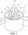
- the axis A of the drilling tool and the axis of the conduit 20 are preferably substantially coincident, the conduit 20 extending vertically the drilling tool when the latter is oriented vertically, the tip 30 upwards.
- the drilling tool can comprise several lateral openings 32, distributed around the axis A of the drilling tool and for example four in number, each opening extending along an angular sector, in particular less than 90°.
- such a discharge device is used by piercing the wall of the packaging using the piercing tool and until the shoulder 4 abuts against the external surface of the packaging.
- the discharge takes place when the device is held in a position where the axis of the piercing tool is substantially vertical, the tip 30 directed upwards; the granular material flows, from the packaging, through said lateral opening into the hollow of the piercing tool 3, through the inlet mouth 21, and up to the outlet mouth 22 where the granular material escapes.
- the discharge device 1 may comprise the following features, at least according to one embodiment.
- Said shoulder 4 with a stop function configured to come into contact with the wall of the packaging ensuring the stopping of the discharge device when said wall is pierced by the piercing tool 3, is notably in a position where said lateral opening 32 extends over a first part of length L1 inside the packaging and over a second part of length L2 outside the packaging where said lateral opening forms an air inlet.
- each lateral opening penetrates into the packaging on the first part of length L1 of the lateral opening 32, where said lateral opening allows the entry of granular material into the hollow. of the drilling tool, and extends over the second part of length L2, outside the packaging where it forms an air inlet.
- the second portion of length L2 of the lateral opening provides a lateral air inlet, at the first end of the tubular body 2, counter-current to the granular material flowing by gravity, illustrated by a double arrow.
- This lateral air inlet is advantageously in addition to the possible air inlet which takes place axially from the outlet mouth 22 through the conduit 20 of the tubular body.
- the L2/L1 ratio can be between 0.05 and 0.25 such as 0.1.
- the lateral air inlet(s) formed by said lateral opening 32 substantially increases the quantity of air entering the vacuum packaging, avoiding the creation of a vacuum caused by the flow of the granular material, which promotes the flow of the material coming from the vacuum packaging: the flow is substantially better and allows the granular contents of the vacuum packaging to be emptied quickly, even when the discharge device is kept static, with the tip upwards.
- the device comprises a bowl 5, shaped on the first end of the tubular body 2, arranged on the periphery around the drilling tool 3, in particular at 360° around the drilling tool 3.
- This bowl 5 is positioned intermediate between said shoulder 4 and the widened base 31 of the drilling tool:
- the slope of the bowl is advantageously inclined towards the drilling tool 3 and configured (when the tool drilling tool is oriented vertically, the tip 30 of the drilling tool pointing upwards), so as to bring back by gravity the granular material having escaped the hollow part of the drilling tool inside the hollow part, through the second part of length L2 of the lateral opening 32.
- the bowl 5 thus advantageously has the function of bringing back into the conduit 20 the granular material which escapes laterally through said lateral opening 32.
- said discharge device is configured to ensure the continuous emptying of the contents of the vacuum packaging, when the discharge device is oriented vertically, the tip upwards, the granular material flowing by gravity through said lateral opening 32 via the inlet mouth 21 and to the outlet mouth 22 by gravity, against the flow of the air penetrating the packaging in particular via the axial air inlet formed by the pipe 20, and possibly where appropriate via the lateral air inlet(s) through said lateral opening 32.
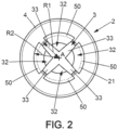
- the widened base of the drilling tool having an external radius R1 relative to an axis A of the drilling tool, the lower part of the bowl 5 having, at the level of said lateral opening 32, a recess 50, in excess of the depth of the wall of the bowl 5 communicating with the conduit 20 of the tubular body 2.
- This recess 50 is notably configured so that the inlet mouth 21 extends radially outwardly beyond the radius R1 of the widened base 31 of the drilling tool, at least in line with said at least one lateral opening 32.
- Such a recess 50 further promotes the return of the granular material from the bowl 5 to the inlet mouth 21, avoiding the accumulation of material in the bowl 5, outside the drilling tool 3.
- Such a recess 50 can be provided at the right of each lateral opening 32.
- the inlet mouth 21 can thus extend at the right of the lateral opening 32 up to a radius R2 relative to the axis A of the drilling tool, greater than the external radius R1 of the widened base 31 of the drilling tool 3, and as visible at the figure 2 .
- the drilling tool 3 may have a bullet shape, comprising bullet arcs 33 each extending from the widened base 31 of the drilling tool 3 to the tip 30 of the drilling tool where the bullet arcs 33 meet.
- Said at least one lateral opening 32 may comprise a plurality of lateral openings 32.
- Each lateral opening 32 preferably extends from the widened base 31 between two of the consecutive bullet arcs 33, over all or part of the length of the drilling tool in the direction of the tip 30.
- the piercing tool 3 comprises a locking groove 34 intended to directly receive the wall edge of the packaging P or indirectly via an annular ring B secured to the wall of the packaging P.
- the locking groove 34 is configured so as to ensure that the piercing tool is held on the packaging once the packaging has been pierced by the piercing tool 3.
- the locking groove 34 makes it possible to ensure that the discharge device 1 is held on the wall of the packaging, suspended from the packaging, and without the operator needing to hold the discharge device 1.
- the locking groove 34 is formed by a plurality of notches 35, for example on the ogive arcs 33, located on the same radius relative to the axis A of the drilling tool.
- the notches 35 are positioned along the axis A of the drilling tool at the level of said shoulder 4 in the direction of the axis A, at a distance from the widened base 31 of the drilling tool along said direction of the axis A and such that said lateral opening 32 extends in height, when the wall of the packaging is blocked by the notches 35 of the blocking groove 34, both, on the one hand, inside the packaging on said first part of length L1 of the piercing tool 3 located between the tip 30 and the blocking groove 34, and on the other hand, outside the packaging on the second part of length L2 of the piercing tool 3 which extends between the blocking groove 34 and the widened base 31.
- said lateral opening forms said lateral air inlet.
- the locking groove allows direct engagement with the edge of the packaging wall as shown in the figure 4 or indirectly via an annular ring B secured to the wall of the packaging, and as visible at the figure 6 .
- a vacuum packaging P which is not part of the invention, containing a granular material, as well as an annular ring B secured to the wall of the packaging, configured to lock into the stop groove 34 of a discharge device 1.
- the external surface of the sealed wall of the vacuum packaging intended to be pierced, where appropriate at the level of the annular ring B, is isolated from external contamination by a peelable sheet Pel, intended to be removed before piercing.
- This surface can preferably be asepticized or sterilized, just before the application of the peelable sheet Pel.
- the variant of the figure 9 notably includes a radially projecting stop 37 of the drilling tool (replacing the locking groove 34 of the figure 1 ), more particularly in the form of a ring, substantially perpendicular to the axis A of the drilling tool.
- This ring connects the ogive arcs 33 of the drilling tool together.
- This stop 37 is positioned substantially at the same level as said shoulder 4, in the direction of the axis A, at a distance from the widened base 31 in this direction A.
- This stop is preceded by a screw thread, 38, which connects the ogive arcs 33 of the drilling tool together.
- the installation of the discharge device is ensured by piercing the flexible wall of the packaging with the tip 31 of the piercing tool 3, then by screwing the screw thread 38 with the flexible wall of the packaging and until the flexible wall is pinched between the stop ring 37 and an immediately adjacent portion of the screw thread 38 when the wall of the packaging comes into contact with said shoulder 4.
- the tubular body 2 and piercing tool 3 assembly is configured as a hand-held, portable, hand-operable tool, configured to manually pierce and empty the granular material from a vacuum package.
- the discharge device is an integral part of a production unit, permanently fixed to the production unit, with the tip of the drilling tool facing upwards.
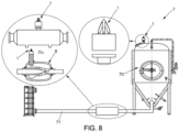
- the invention further relates to a production unit 7 such as a fermentation unit comprising an enclosure 70 forming a fermentation tank as well as a discharge device 1 according to the invention mounted integral with said enclosure 70 or integral with a pipe 71 of said production unit, the piercing tool vertical, the tip oriented upwards, said discharge device being configured to transfer a granular material contained in a vacuum packaging into said enclosure 70, directly into said enclosure, or indirectly via said pipe 71.
- a production unit 7 such as a fermentation unit comprising an enclosure 70 forming a fermentation tank as well as a discharge device 1 according to the invention mounted integral with said enclosure 70 or integral with a pipe 71 of said production unit, the piercing tool vertical, the tip oriented upwards, said discharge device being configured to transfer a granular material contained in a vacuum packaging into said enclosure 70, directly into said enclosure, or indirectly via said pipe 71.
- the second end of the tubular body is fixed in a sealed manner to said enclosure 70, in particular to the fermentation tank or to the pipeline, for example by means of a tapping 23 at the outlet mouth 22 cooperating by screwing with a threaded connection of the production unit.
- Any other type of connection can be used to ensure the fixing of the second end to the tank or to the pipeline such as a connection according to the SMS standard or a connection known to those skilled in the art under the name of "CLAMP connection"
- the tubular body of the discharge device is integral with said enclosure 70 in a sealed manner, so that the outlet mouth 22 is in communication with the internal volume of the fermentation tank.
- the discharge device is fixed in the upper part of the tank, configured so that the granular material flows from the outlet mouth 22 to the interior of said enclosure 70, in particular the tank by gravity.
- said enclosure 70 in particular the fermentation tank 70 being supplied with products in a forced manner by the pipe 71, said tubular body of the discharge device is coupled in a sealed manner to the pipe 71 directly or indirectly via a transfer system so that the granular material flows into the pipe 71 while mixing with the products, and before said granular material is conveyed, together with the products into said enclosure 70.
- a transfer system such as a venturi 8 can be used, through which the fluid from the pipeline passes, the depression generated by the venturi 8 sucking up the granular material to mix it with the fluid downstream of the venturi.
- the present disclosure also relates to equipment which comprises a fermentation unit 7 according to the invention, as well as a shutter 6 cooperating in a sealed manner with the first end of the tubular body, covering (in the closed position) the drilling tool and the bowl by forming a sealed chamber 60 for a fluid.
- This chamber is defined between the inner wall of the shutter 6, on the one hand, and the drilling tool 3, (the bowl 5 if applicable) and the shoulder 4, on the other hand, said sealed chamber in communication with the conduit 20 of the tubular body via said at least one lateral opening.
- a shutter 6 in addition to its function as a shutter element of the inlet mouth, can advantageously allow the implementation of a cleaning and disinfection method.
- the shutter 6 can be screwed to the tubular body, the shutter having a tapping cooperating with an external thread of the tubular body, at the first end of the tubular body.
- the shutter 6 can be fixed to the tubular body of the device by any type of connector, such as an SMS connector or CLAMP connector.
- the hollow of the drilling tool may have a flat 36 on the underside of the drilling tool, opposite the tip 30, preventing the retention of products.
- this cleaning and disinfection step can advantageously be simultaneous with the cleaning and/or disinfection of the production unit 7.
- the fluid injection step ensuring the disinfection of the interior surfaces of the piercing tool and the conduit of the tubular body of the discharge device 1 and the exterior surfaces of the piercing tool, the bowl and the shoulder is an injection simultaneously ensuring the cleaning of the internal surfaces of the fermentation unit.
- the disinfection of the discharge device is ensured simultaneously using the cleaning step of the fermentation unit.
- the pouring device will find particular application for emptying a vacuum package containing active dry yeast, for example during the production of beer.
Landscapes
- Engineering & Computer Science (AREA)
- Mechanical Engineering (AREA)
- Life Sciences & Earth Sciences (AREA)
- Forests & Forestry (AREA)
- Control And Other Processes For Unpacking Of Materials (AREA)
- Packages (AREA)
- Details Of Rigid Or Semi-Rigid Containers (AREA)
- Basic Packing Technique (AREA)
- Closures For Containers (AREA)
- Filling Or Emptying Of Bunkers, Hoppers, And Tanks (AREA)
- Medical Preparation Storing Or Oral Administration Devices (AREA)
- Vacuum Packaging (AREA)
Applications Claiming Priority (2)
| Application Number | Priority Date | Filing Date | Title |
|---|---|---|---|
| FR1915023A FR3105059B1 (fr) | 2019-12-19 | 2019-12-19 | Dispositif déverseur |
| PCT/FR2020/052507 WO2021123645A1 (fr) | 2019-12-19 | 2020-12-17 | Dispositif déverseur |
Publications (3)
| Publication Number | Publication Date |
|---|---|
| EP4077152A1 EP4077152A1 (fr) | 2022-10-26 |
| EP4077152B1 true EP4077152B1 (fr) | 2024-08-14 |
| EP4077152C0 EP4077152C0 (fr) | 2024-08-14 |
Family
ID=70154567
Family Applications (1)
| Application Number | Title | Priority Date | Filing Date |
|---|---|---|---|
| EP20848805.6A Active EP4077152B1 (fr) | 2019-12-19 | 2020-12-17 | Unité de production |
Country Status (16)
Families Citing this family (2)
| Publication number | Priority date | Publication date | Assignee | Title |
|---|---|---|---|---|
| FR3105059B1 (fr) * | 2019-12-19 | 2022-02-25 | Lesaffre & Cie | Dispositif déverseur |
| FR3105058B1 (fr) * | 2019-12-19 | 2022-02-25 | Lesaffre & Cie | Dispositif déverseur |
Family Cites Families (39)
| Publication number | Priority date | Publication date | Assignee | Title |
|---|---|---|---|---|
| GB719054A (en) | 1950-10-05 | 1954-11-24 | Joseph Reginald Howden | A new or improved device for dispensing powders, granulated substances and the like in measured quantities |
| FR1280014A (fr) * | 1960-11-15 | 1961-12-29 | Ferembal Sa | Dispositif perceur-verseur pour récipients en métal ou autre matière |
| JPS5541305U (cg-RX-API-DMAC7.html) * | 1978-09-08 | 1980-03-17 | ||
| DE3544244A1 (de) * | 1985-12-14 | 1987-06-25 | Minnesota Mining & Mfg | Vorrichtung zum entnehmen von fuellgut aus beuteln |
| US4883198A (en) * | 1987-10-06 | 1989-11-28 | Manska Wayne E | Container and method for dispensing semi-solid substances |
| US5325995A (en) * | 1989-07-27 | 1994-07-05 | Du Pont Canada Inc. | Piercing nozzle for pouch fitment |
| US4993569A (en) * | 1989-08-03 | 1991-02-19 | Abbott Laboratories | Piercing closure |
| GB8922477D0 (en) * | 1989-10-05 | 1989-11-22 | Procter & Gamble | Funnel with piercing device for flowable product package |
| US5405053A (en) * | 1993-08-04 | 1995-04-11 | Uneco Engineering, Inc. | Bulk bag opener and dispenser |
| FI98804C (fi) | 1994-06-14 | 1997-08-25 | Tuomo Halonen Oy | Tyhjennysventtiili nestepakkausten, kuten nestepussien, tyhjentämistä varten |
| US5855298A (en) * | 1994-08-18 | 1999-01-05 | Creamiser Products Corporation | Tapping stem for liquid supply container |
| US5573047A (en) * | 1995-07-03 | 1996-11-12 | Akin; Richard M. | Seal-piercing insert for a bottled water dispenser |
| US6095433A (en) * | 1997-08-28 | 2000-08-01 | Langdon (London) Limited | Irrigation system and method of performing same |
| SE514699C2 (sv) * | 1997-09-29 | 2001-04-02 | Asept Int Ab | Portioneringsanordning och förpackning ur vilken en flytande produkt, företrädesvis flytande livsmedel, skall portioneras ut med hjälp av portioneringsanordningen samt kopplingsanordning vid nämnda förpackning |
| US6223940B1 (en) * | 1998-11-09 | 2001-05-01 | Radius International Limited Partnership | Fluid storage container and dispenser, and method of dispensing |
| US6089406A (en) * | 1999-06-01 | 2000-07-18 | Server Products | Packaged food warmer and dispenser |
| US6378730B1 (en) | 2000-10-27 | 2002-04-30 | Nestec S.A. | Quick-locking device for effecting hygienic transfer of flowable material from a container by piercing |
| US7322492B2 (en) | 2000-12-20 | 2008-01-29 | Sankyo Seiyakukogyo Co., Ltd. | Adaptor for beverage pack and beverage feeder |
| DE10104112A1 (de) * | 2001-01-31 | 2002-08-01 | Edelmann Carl Verpackung | Verfahren zum Einbringen einer Auslaßöffnung in eine mit einer Innenfolie versehenen Verpackung |
| US6986324B2 (en) * | 2001-10-19 | 2006-01-17 | Hydropac/Lab Products, Inc. | Fluid delivery valve system and method |
| US20040238563A1 (en) * | 2003-06-02 | 2004-12-02 | Chien-Fu Lin | Dispensing apparatus for pack of drink |
| MXPA06002172A (es) * | 2003-08-25 | 2006-05-22 | Henry Macler Ii | Enfriador portatil de agua con fluidos en bolsas. |
| WO2005040034A2 (en) * | 2003-10-23 | 2005-05-06 | Don Miller | Container adapted to hold and dispense bagged fluids |
| US7357277B2 (en) * | 2004-08-30 | 2008-04-15 | Scholle Corporation | Cap assembly and container used therewith |
| US20090206106A1 (en) * | 2005-02-10 | 2009-08-20 | Alejandro Perez Ordonez | Purified water dispensing system |
| US7607555B2 (en) * | 2006-03-01 | 2009-10-27 | Ds Smith Plastics Limited | Puncturable cap and piercer |
| US7708164B2 (en) * | 2006-11-06 | 2010-05-04 | Fres-Co System Usa, Inc. | Volumetric dispensing fitment and package including the same |
| JP3129185U (ja) * | 2006-11-24 | 2007-02-08 | 株式会社 日宝 | 詰め替え補助器具 |
| US7654413B2 (en) * | 2007-04-17 | 2010-02-02 | Kuei-Tang Chang | Supporting device for package water dispenser |
| GB2457041A (en) * | 2008-01-31 | 2009-08-05 | Claire Mitchell | Delivery device for a container |
| US8291947B2 (en) * | 2008-02-28 | 2012-10-23 | Sunbeam Products, Inc. | Water bottle adaptor for an appliance |
| MY157230A (en) * | 2009-04-06 | 2016-05-13 | Internat Packaging Innovations Llc | Ribbed water spike |
| US8353428B2 (en) * | 2009-07-21 | 2013-01-15 | Fres-Co System Usa, Inc. | Volumetric metering fitment and package including the same |
| DE102011017509A1 (de) * | 2011-04-26 | 2012-10-31 | Robert Bosch Gmbh | Verschluss mit Adapter |
| US8627975B1 (en) * | 2012-09-05 | 2014-01-14 | Gordon Whitbeck | Content-saving systems for sealing opened product tubes and preventing product hardening |
| US20140103065A1 (en) * | 2012-10-12 | 2014-04-17 | Coravin, Llc | Non-coring reduced shearing needle |
| US9579686B2 (en) | 2012-10-29 | 2017-02-28 | Nordson Corporation | Fluid dispensing assemblies and methods of dispensing fluids from containers |
| FR3105059B1 (fr) * | 2019-12-19 | 2022-02-25 | Lesaffre & Cie | Dispositif déverseur |
| FR3105058B1 (fr) * | 2019-12-19 | 2022-02-25 | Lesaffre & Cie | Dispositif déverseur |
-
2019
- 2019-12-19 FR FR1915023A patent/FR3105059B1/fr active Active
-
2020
- 2020-12-16 TW TW109144455A patent/TWI873251B/zh active
- 2020-12-17 BR BR112022012041A patent/BR112022012041A2/pt active IP Right Grant
- 2020-12-17 AU AU2020410074A patent/AU2020410074A1/en active Pending
- 2020-12-17 CN CN202080088272.5A patent/CN114829264B/zh active Active
- 2020-12-17 JP JP2022531639A patent/JP7720839B2/ja active Active
- 2020-12-17 AR ARP200103527A patent/AR120797A1/es active IP Right Grant
- 2020-12-17 MX MX2022007401A patent/MX2022007401A/es unknown
- 2020-12-17 EP EP20848805.6A patent/EP4077152B1/fr active Active
- 2020-12-17 US US17/786,153 patent/US12110221B2/en active Active
- 2020-12-17 CA CA3160802A patent/CA3160802A1/fr active Pending
- 2020-12-17 ES ES20848805T patent/ES2993109T3/es active Active
- 2020-12-17 KR KR1020227020750A patent/KR20220111686A/ko active Pending
- 2020-12-17 WO PCT/FR2020/052507 patent/WO2021123645A1/fr not_active Ceased
- 2020-12-17 PL PL20848805.6T patent/PL4077152T3/pl unknown
-
2022
- 2022-07-18 ZA ZA2022/07967A patent/ZA202207967B/en unknown
Also Published As
| Publication number | Publication date |
|---|---|
| JP2023506393A (ja) | 2023-02-16 |
| CN114829264A (zh) | 2022-07-29 |
| FR3105059A1 (fr) | 2021-06-25 |
| CN114829264B (zh) | 2024-05-14 |
| AU2020410074A1 (en) | 2022-06-23 |
| TWI873251B (zh) | 2025-02-21 |
| PL4077152T3 (pl) | 2024-12-16 |
| CA3160802A1 (fr) | 2021-06-24 |
| ZA202207967B (en) | 2023-04-26 |
| US20230312320A1 (en) | 2023-10-05 |
| BR112022012041A2 (pt) | 2022-09-06 |
| ES2993109T3 (en) | 2024-12-23 |
| TW202138280A (zh) | 2021-10-16 |
| US12110221B2 (en) | 2024-10-08 |
| EP4077152A1 (fr) | 2022-10-26 |
| KR20220111686A (ko) | 2022-08-09 |
| FR3105059B1 (fr) | 2022-02-25 |
| EP4077152C0 (fr) | 2024-08-14 |
| WO2021123645A1 (fr) | 2021-06-24 |
| JP7720839B2 (ja) | 2025-08-08 |
| MX2022007401A (es) | 2022-07-13 |
| AR120797A1 (es) | 2022-03-16 |
Similar Documents
| Publication | Publication Date | Title |
|---|---|---|
| EP2864216B1 (fr) | Dispositif distributeur mélangeur | |
| EP4077152B1 (fr) | Unité de production | |
| LU84334A1 (fr) | Dispositif de fourniture de solution sterile et de son remplacement par de l'air | |
| EP2205496A2 (fr) | Recipient de traitement d'un produit biopharmaceutique comprenant des moyens de protection | |
| EP4077151A1 (fr) | Dispositif déverseur | |
| FR2946905A1 (fr) | Dispositif de depoussierage, dans le cadre de transfert de produits pulverulents, installation, procede de depoussierage, procede de trasfert, et procede de sterilisation utilisant ledit dispositif | |
| EP1978168B1 (fr) | Distributeur de liquides d' entretien à compartiments multiples pour cuvettes de toilettes | |
| EP1682056B1 (fr) | Ensemble de conditionnement et de distribution de liquide a membranes microfiltrantes | |
| FR2511242A1 (fr) | Dispositif de fourniture de solution sterile et de son remplacement par de l'air | |
| EP1294460B1 (fr) | Dispositif de piegeage de produits a eliminer, a usage industriel ou medical | |
| FR2944978A1 (fr) | Dispositif de filtration pourvu de moyens d'aspiration | |
| FR2507578A1 (fr) | Dispositif d'ecoulement | |
| WO2024245883A1 (fr) | Raccord pour un système de fermeture d'un flacon et/ou un distributeur de produit fluide | |
| WO2025237956A1 (fr) | Dispositif de bouchage anticontamination multidose | |
| FR2701249A1 (fr) | Dispositif de fermeture de l'extrémité d'un tube à paroi souple. | |
| BE1025937A1 (fr) | Element de prehension d'un objet | |
| FR2719291A1 (fr) | Dispositif et procédé de vidange de conteneur souple. | |
| BE539835A (cg-RX-API-DMAC7.html) |
Legal Events
| Date | Code | Title | Description |
|---|---|---|---|
| STAA | Information on the status of an ep patent application or granted ep patent |
Free format text: STATUS: UNKNOWN |
|
| STAA | Information on the status of an ep patent application or granted ep patent |
Free format text: STATUS: THE INTERNATIONAL PUBLICATION HAS BEEN MADE |
|
| PUAI | Public reference made under article 153(3) epc to a published international application that has entered the european phase |
Free format text: ORIGINAL CODE: 0009012 |
|
| STAA | Information on the status of an ep patent application or granted ep patent |
Free format text: STATUS: REQUEST FOR EXAMINATION WAS MADE |
|
| 17P | Request for examination filed |
Effective date: 20220616 |
|
| AK | Designated contracting states |
Kind code of ref document: A1 Designated state(s): AL AT BE BG CH CY CZ DE DK EE ES FI FR GB GR HR HU IE IS IT LI LT LU LV MC MK MT NL NO PL PT RO RS SE SI SK SM TR |
|
| DAV | Request for validation of the european patent (deleted) | ||
| DAX | Request for extension of the european patent (deleted) | ||
| GRAP | Despatch of communication of intention to grant a patent |
Free format text: ORIGINAL CODE: EPIDOSNIGR1 |
|
| STAA | Information on the status of an ep patent application or granted ep patent |
Free format text: STATUS: GRANT OF PATENT IS INTENDED |
|
| INTG | Intention to grant announced |
Effective date: 20240105 |
|
| GRAJ | Information related to disapproval of communication of intention to grant by the applicant or resumption of examination proceedings by the epo deleted |
Free format text: ORIGINAL CODE: EPIDOSDIGR1 |
|
| STAA | Information on the status of an ep patent application or granted ep patent |
Free format text: STATUS: REQUEST FOR EXAMINATION WAS MADE |
|
| GRAP | Despatch of communication of intention to grant a patent |
Free format text: ORIGINAL CODE: EPIDOSNIGR1 |
|
| STAA | Information on the status of an ep patent application or granted ep patent |
Free format text: STATUS: GRANT OF PATENT IS INTENDED |
|
| INTC | Intention to grant announced (deleted) | ||
| INTG | Intention to grant announced |
Effective date: 20240326 |
|
| GRAS | Grant fee paid |
Free format text: ORIGINAL CODE: EPIDOSNIGR3 |
|
| GRAA | (expected) grant |
Free format text: ORIGINAL CODE: 0009210 |
|
| STAA | Information on the status of an ep patent application or granted ep patent |
Free format text: STATUS: THE PATENT HAS BEEN GRANTED |
|
| AK | Designated contracting states |
Kind code of ref document: B1 Designated state(s): AL AT BE BG CH CY CZ DE DK EE ES FI FR GB GR HR HU IE IS IT LI LT LU LV MC MK MT NL NO PL PT RO RS SE SI SK SM TR |
|
| REG | Reference to a national code |
Ref country code: GB Ref legal event code: FG4D Free format text: NOT ENGLISH |
|
| REG | Reference to a national code |
Ref country code: CH Ref legal event code: EP |
|
| REG | Reference to a national code |
Ref country code: DE Ref legal event code: R096 Ref document number: 602020035936 Country of ref document: DE |
|
| REG | Reference to a national code |
Ref country code: IE Ref legal event code: FG4D Free format text: LANGUAGE OF EP DOCUMENT: FRENCH |
|
| U01 | Request for unitary effect filed |
Effective date: 20240906 |
|
| U07 | Unitary effect registered |
Designated state(s): AT BE BG DE DK EE FI FR IT LT LU LV MT NL PT RO SE SI Effective date: 20240923 |
|
| REG | Reference to a national code |
Ref country code: ES Ref legal event code: FG2A Ref document number: 2993109 Country of ref document: ES Kind code of ref document: T3 Effective date: 20241223 |
|
| U20 | Renewal fee for the european patent with unitary effect paid |
Year of fee payment: 5 Effective date: 20241127 |
|
| PG25 | Lapsed in a contracting state [announced via postgrant information from national office to epo] |
Ref country code: NO Free format text: LAPSE BECAUSE OF FAILURE TO SUBMIT A TRANSLATION OF THE DESCRIPTION OR TO PAY THE FEE WITHIN THE PRESCRIBED TIME-LIMIT Effective date: 20241114 |
|
| PG25 | Lapsed in a contracting state [announced via postgrant information from national office to epo] |
Ref country code: GR Free format text: LAPSE BECAUSE OF FAILURE TO SUBMIT A TRANSLATION OF THE DESCRIPTION OR TO PAY THE FEE WITHIN THE PRESCRIBED TIME-LIMIT Effective date: 20241115 |
|
| PG25 | Lapsed in a contracting state [announced via postgrant information from national office to epo] |
Ref country code: IS Free format text: LAPSE BECAUSE OF FAILURE TO SUBMIT A TRANSLATION OF THE DESCRIPTION OR TO PAY THE FEE WITHIN THE PRESCRIBED TIME-LIMIT Effective date: 20241214 |
|
| PG25 | Lapsed in a contracting state [announced via postgrant information from national office to epo] |
Ref country code: HR Free format text: LAPSE BECAUSE OF FAILURE TO SUBMIT A TRANSLATION OF THE DESCRIPTION OR TO PAY THE FEE WITHIN THE PRESCRIBED TIME-LIMIT Effective date: 20240814 |
|
| PG25 | Lapsed in a contracting state [announced via postgrant information from national office to epo] |
Ref country code: RS Free format text: LAPSE BECAUSE OF FAILURE TO SUBMIT A TRANSLATION OF THE DESCRIPTION OR TO PAY THE FEE WITHIN THE PRESCRIBED TIME-LIMIT Effective date: 20241114 |
|
| PG25 | Lapsed in a contracting state [announced via postgrant information from national office to epo] |
Ref country code: RS Free format text: LAPSE BECAUSE OF FAILURE TO SUBMIT A TRANSLATION OF THE DESCRIPTION OR TO PAY THE FEE WITHIN THE PRESCRIBED TIME-LIMIT Effective date: 20241114 Ref country code: NO Free format text: LAPSE BECAUSE OF FAILURE TO SUBMIT A TRANSLATION OF THE DESCRIPTION OR TO PAY THE FEE WITHIN THE PRESCRIBED TIME-LIMIT Effective date: 20241114 Ref country code: IS Free format text: LAPSE BECAUSE OF FAILURE TO SUBMIT A TRANSLATION OF THE DESCRIPTION OR TO PAY THE FEE WITHIN THE PRESCRIBED TIME-LIMIT Effective date: 20241214 Ref country code: HR Free format text: LAPSE BECAUSE OF FAILURE TO SUBMIT A TRANSLATION OF THE DESCRIPTION OR TO PAY THE FEE WITHIN THE PRESCRIBED TIME-LIMIT Effective date: 20240814 Ref country code: GR Free format text: LAPSE BECAUSE OF FAILURE TO SUBMIT A TRANSLATION OF THE DESCRIPTION OR TO PAY THE FEE WITHIN THE PRESCRIBED TIME-LIMIT Effective date: 20241115 |
|
| PG25 | Lapsed in a contracting state [announced via postgrant information from national office to epo] |
Ref country code: SM Free format text: LAPSE BECAUSE OF FAILURE TO SUBMIT A TRANSLATION OF THE DESCRIPTION OR TO PAY THE FEE WITHIN THE PRESCRIBED TIME-LIMIT Effective date: 20240814 |
|
| PG25 | Lapsed in a contracting state [announced via postgrant information from national office to epo] |
Ref country code: SK Free format text: LAPSE BECAUSE OF FAILURE TO SUBMIT A TRANSLATION OF THE DESCRIPTION OR TO PAY THE FEE WITHIN THE PRESCRIBED TIME-LIMIT Effective date: 20240814 |
|
| PLBE | No opposition filed within time limit |
Free format text: ORIGINAL CODE: 0009261 |
|
| STAA | Information on the status of an ep patent application or granted ep patent |
Free format text: STATUS: NO OPPOSITION FILED WITHIN TIME LIMIT |
|
| PG25 | Lapsed in a contracting state [announced via postgrant information from national office to epo] |
Ref country code: MC Free format text: LAPSE BECAUSE OF FAILURE TO SUBMIT A TRANSLATION OF THE DESCRIPTION OR TO PAY THE FEE WITHIN THE PRESCRIBED TIME-LIMIT Effective date: 20240814 |
|
| 26N | No opposition filed |
Effective date: 20250515 |
|
| REG | Reference to a national code |
Ref country code: CH Ref legal event code: PL |
|
| PG25 | Lapsed in a contracting state [announced via postgrant information from national office to epo] |
Ref country code: CH Free format text: LAPSE BECAUSE OF NON-PAYMENT OF DUE FEES Effective date: 20241231 |
|
| PG25 | Lapsed in a contracting state [announced via postgrant information from national office to epo] |
Ref country code: IE Free format text: LAPSE BECAUSE OF NON-PAYMENT OF DUE FEES Effective date: 20241217 |
|
| U20 | Renewal fee for the european patent with unitary effect paid |
Year of fee payment: 6 Effective date: 20251127 |
|
| PGFP | Annual fee paid to national office [announced via postgrant information from national office to epo] |
Ref country code: GB Payment date: 20251229 Year of fee payment: 6 |
|
| PGFP | Annual fee paid to national office [announced via postgrant information from national office to epo] |
Ref country code: CZ Payment date: 20251217 Year of fee payment: 6 |
|
| PGFP | Annual fee paid to national office [announced via postgrant information from national office to epo] |
Ref country code: PL Payment date: 20251125 Year of fee payment: 6 |
|
| PGFP | Annual fee paid to national office [announced via postgrant information from national office to epo] |
Ref country code: ES Payment date: 20260112 Year of fee payment: 6 |