EP4074568A1 - Verfahren zur ansteuerung eines notreaktionssystems - Google Patents
Verfahren zur ansteuerung eines notreaktionssystems Download PDFInfo
- Publication number
- EP4074568A1 EP4074568A1 EP21168608.4A EP21168608A EP4074568A1 EP 4074568 A1 EP4074568 A1 EP 4074568A1 EP 21168608 A EP21168608 A EP 21168608A EP 4074568 A1 EP4074568 A1 EP 4074568A1
- Authority
- EP
- European Patent Office
- Prior art keywords
- motor vehicle
- vehicle occupant
- emergency
- vehicle
- health conditions
- Prior art date
- Legal status (The legal status is an assumption and is not a legal conclusion. Google has not performed a legal analysis and makes no representation as to the accuracy of the status listed.)
- Pending
Links
- 238000000034 method Methods 0.000 title claims abstract description 46
- 230000036541 health Effects 0.000 claims abstract description 53
- 238000012544 monitoring process Methods 0.000 claims abstract description 14
- 238000012806 monitoring device Methods 0.000 claims description 10
- 230000000007 visual effect Effects 0.000 claims description 7
- 208000003443 Unconsciousness Diseases 0.000 claims description 4
- 239000008280 blood Substances 0.000 claims description 4
- 210000004369 blood Anatomy 0.000 claims description 4
- 230000001815 facial effect Effects 0.000 claims description 3
- 230000003252 repetitive effect Effects 0.000 claims description 3
- 230000036387 respiratory rate Effects 0.000 claims description 3
- 238000004891 communication Methods 0.000 description 5
- 230000006870 function Effects 0.000 description 5
- 230000008569 process Effects 0.000 description 4
- 238000012552 review Methods 0.000 description 3
- QVGXLLKOCUKJST-UHFFFAOYSA-N atomic oxygen Chemical compound [O] QVGXLLKOCUKJST-UHFFFAOYSA-N 0.000 description 2
- 230000036772 blood pressure Effects 0.000 description 2
- 230000007812 deficiency Effects 0.000 description 2
- 238000010586 diagram Methods 0.000 description 2
- 229910052760 oxygen Inorganic materials 0.000 description 2
- 239000001301 oxygen Substances 0.000 description 2
- 230000002093 peripheral effect Effects 0.000 description 2
- 230000004044 response Effects 0.000 description 2
- 230000001960 triggered effect Effects 0.000 description 2
- LFQSCWFLJHTTHZ-UHFFFAOYSA-N Ethanol Chemical compound CCO LFQSCWFLJHTTHZ-UHFFFAOYSA-N 0.000 description 1
- 230000009471 action Effects 0.000 description 1
- 238000013459 approach Methods 0.000 description 1
- 238000013473 artificial intelligence Methods 0.000 description 1
- 238000009610 ballistocardiography Methods 0.000 description 1
- 230000006399 behavior Effects 0.000 description 1
- 230000003542 behavioural effect Effects 0.000 description 1
- 230000005540 biological transmission Effects 0.000 description 1
- 230000004397 blinking Effects 0.000 description 1
- 230000036765 blood level Effects 0.000 description 1
- 208000016252 change in skin color Diseases 0.000 description 1
- 238000004590 computer program Methods 0.000 description 1
- 238000013461 design Methods 0.000 description 1
- 238000001514 detection method Methods 0.000 description 1
- 229910003460 diamond Inorganic materials 0.000 description 1
- 239000010432 diamond Substances 0.000 description 1
- 230000009429 distress Effects 0.000 description 1
- 238000002565 electrocardiography Methods 0.000 description 1
- 230000004424 eye movement Effects 0.000 description 1
- 230000008921 facial expression Effects 0.000 description 1
- 238000010801 machine learning Methods 0.000 description 1
- 230000007257 malfunction Effects 0.000 description 1
- 238000010295 mobile communication Methods 0.000 description 1
- 238000012986 modification Methods 0.000 description 1
- 230000004048 modification Effects 0.000 description 1
- 208000010125 myocardial infarction Diseases 0.000 description 1
- 230000003287 optical effect Effects 0.000 description 1
- 238000012545 processing Methods 0.000 description 1
- 238000003672 processing method Methods 0.000 description 1
- 230000001902 propagating effect Effects 0.000 description 1
- 230000035484 reaction time Effects 0.000 description 1
- 238000005096 rolling process Methods 0.000 description 1
- 238000012360 testing method Methods 0.000 description 1
Images


Classifications
-
- B—PERFORMING OPERATIONS; TRANSPORTING
- B60—VEHICLES IN GENERAL
- B60W—CONJOINT CONTROL OF VEHICLE SUB-UNITS OF DIFFERENT TYPE OR DIFFERENT FUNCTION; CONTROL SYSTEMS SPECIALLY ADAPTED FOR HYBRID VEHICLES; ROAD VEHICLE DRIVE CONTROL SYSTEMS FOR PURPOSES NOT RELATED TO THE CONTROL OF A PARTICULAR SUB-UNIT
- B60W50/00—Details of control systems for road vehicle drive control not related to the control of a particular sub-unit, e.g. process diagnostic or vehicle driver interfaces
- B60W50/08—Interaction between the driver and the control system
- B60W50/14—Means for informing the driver, warning the driver or prompting a driver intervention
-
- H—ELECTRICITY
- H04—ELECTRIC COMMUNICATION TECHNIQUE
- H04M—TELEPHONIC COMMUNICATION
- H04M1/00—Substation equipment, e.g. for use by subscribers
- H04M1/72—Mobile telephones; Cordless telephones, i.e. devices for establishing wireless links to base stations without route selection
- H04M1/724—User interfaces specially adapted for cordless or mobile telephones
- H04M1/72403—User interfaces specially adapted for cordless or mobile telephones with means for local support of applications that increase the functionality
- H04M1/72418—User interfaces specially adapted for cordless or mobile telephones with means for local support of applications that increase the functionality for supporting emergency services
- H04M1/72421—User interfaces specially adapted for cordless or mobile telephones with means for local support of applications that increase the functionality for supporting emergency services with automatic activation of emergency service functions, e.g. upon sensing an alarm
-
- B—PERFORMING OPERATIONS; TRANSPORTING
- B60—VEHICLES IN GENERAL
- B60W—CONJOINT CONTROL OF VEHICLE SUB-UNITS OF DIFFERENT TYPE OR DIFFERENT FUNCTION; CONTROL SYSTEMS SPECIALLY ADAPTED FOR HYBRID VEHICLES; ROAD VEHICLE DRIVE CONTROL SYSTEMS FOR PURPOSES NOT RELATED TO THE CONTROL OF A PARTICULAR SUB-UNIT
- B60W60/00—Drive control systems specially adapted for autonomous road vehicles
- B60W60/007—Emergency override
-
- A—HUMAN NECESSITIES
- A61—MEDICAL OR VETERINARY SCIENCE; HYGIENE
- A61B—DIAGNOSIS; SURGERY; IDENTIFICATION
- A61B5/00—Measuring for diagnostic purposes; Identification of persons
- A61B5/02—Detecting, measuring or recording pulse, heart rate, blood pressure or blood flow; Combined pulse/heart-rate/blood pressure determination; Evaluating a cardiovascular condition not otherwise provided for, e.g. using combinations of techniques provided for in this group with electrocardiography or electroauscultation; Heart catheters for measuring blood pressure
- A61B5/0205—Simultaneously evaluating both cardiovascular conditions and different types of body conditions, e.g. heart and respiratory condition
-
- A—HUMAN NECESSITIES
- A61—MEDICAL OR VETERINARY SCIENCE; HYGIENE
- A61B—DIAGNOSIS; SURGERY; IDENTIFICATION
- A61B5/00—Measuring for diagnostic purposes; Identification of persons
- A61B5/02—Detecting, measuring or recording pulse, heart rate, blood pressure or blood flow; Combined pulse/heart-rate/blood pressure determination; Evaluating a cardiovascular condition not otherwise provided for, e.g. using combinations of techniques provided for in this group with electrocardiography or electroauscultation; Heart catheters for measuring blood pressure
- A61B5/024—Detecting, measuring or recording pulse rate or heart rate
-
- A—HUMAN NECESSITIES
- A61—MEDICAL OR VETERINARY SCIENCE; HYGIENE
- A61B—DIAGNOSIS; SURGERY; IDENTIFICATION
- A61B5/00—Measuring for diagnostic purposes; Identification of persons
- A61B5/08—Detecting, measuring or recording devices for evaluating the respiratory organs
- A61B5/0816—Measuring devices for examining respiratory frequency
-
- A—HUMAN NECESSITIES
- A61—MEDICAL OR VETERINARY SCIENCE; HYGIENE
- A61B—DIAGNOSIS; SURGERY; IDENTIFICATION
- A61B5/00—Measuring for diagnostic purposes; Identification of persons
- A61B5/103—Detecting, measuring or recording devices for testing the shape, pattern, colour, size or movement of the body or parts thereof, for diagnostic purposes
- A61B5/11—Measuring movement of the entire body or parts thereof, e.g. head or hand tremor, mobility of a limb
- A61B5/1103—Detecting eye twinkling
-
- A—HUMAN NECESSITIES
- A61—MEDICAL OR VETERINARY SCIENCE; HYGIENE
- A61B—DIAGNOSIS; SURGERY; IDENTIFICATION
- A61B5/00—Measuring for diagnostic purposes; Identification of persons
- A61B5/16—Devices for psychotechnics; Testing reaction times ; Devices for evaluating the psychological state
- A61B5/18—Devices for psychotechnics; Testing reaction times ; Devices for evaluating the psychological state for vehicle drivers or machine operators
-
- A—HUMAN NECESSITIES
- A61—MEDICAL OR VETERINARY SCIENCE; HYGIENE
- A61B—DIAGNOSIS; SURGERY; IDENTIFICATION
- A61B5/00—Measuring for diagnostic purposes; Identification of persons
- A61B5/48—Other medical applications
- A61B5/4806—Sleep evaluation
- A61B5/4809—Sleep detection, i.e. determining whether a subject is asleep or not
-
- A—HUMAN NECESSITIES
- A61—MEDICAL OR VETERINARY SCIENCE; HYGIENE
- A61B—DIAGNOSIS; SURGERY; IDENTIFICATION
- A61B5/00—Measuring for diagnostic purposes; Identification of persons
- A61B5/68—Arrangements of detecting, measuring or recording means, e.g. sensors, in relation to patient
- A61B5/6887—Arrangements of detecting, measuring or recording means, e.g. sensors, in relation to patient mounted on external non-worn devices, e.g. non-medical devices
- A61B5/6893—Cars
-
- B—PERFORMING OPERATIONS; TRANSPORTING
- B60—VEHICLES IN GENERAL
- B60K—ARRANGEMENT OR MOUNTING OF PROPULSION UNITS OR OF TRANSMISSIONS IN VEHICLES; ARRANGEMENT OR MOUNTING OF PLURAL DIVERSE PRIME-MOVERS IN VEHICLES; AUXILIARY DRIVES FOR VEHICLES; INSTRUMENTATION OR DASHBOARDS FOR VEHICLES; ARRANGEMENTS IN CONNECTION WITH COOLING, AIR INTAKE, GAS EXHAUST OR FUEL SUPPLY OF PROPULSION UNITS IN VEHICLES
- B60K28/00—Safety devices for propulsion-unit control, specially adapted for, or arranged in, vehicles, e.g. preventing fuel supply or ignition in the event of potentially dangerous conditions
- B60K28/02—Safety devices for propulsion-unit control, specially adapted for, or arranged in, vehicles, e.g. preventing fuel supply or ignition in the event of potentially dangerous conditions responsive to conditions relating to the driver
- B60K28/06—Safety devices for propulsion-unit control, specially adapted for, or arranged in, vehicles, e.g. preventing fuel supply or ignition in the event of potentially dangerous conditions responsive to conditions relating to the driver responsive to incapacity of driver
- B60K28/066—Safety devices for propulsion-unit control, specially adapted for, or arranged in, vehicles, e.g. preventing fuel supply or ignition in the event of potentially dangerous conditions responsive to conditions relating to the driver responsive to incapacity of driver actuating a signalling device
-
- B—PERFORMING OPERATIONS; TRANSPORTING
- B60—VEHICLES IN GENERAL
- B60K—ARRANGEMENT OR MOUNTING OF PROPULSION UNITS OR OF TRANSMISSIONS IN VEHICLES; ARRANGEMENT OR MOUNTING OF PLURAL DIVERSE PRIME-MOVERS IN VEHICLES; AUXILIARY DRIVES FOR VEHICLES; INSTRUMENTATION OR DASHBOARDS FOR VEHICLES; ARRANGEMENTS IN CONNECTION WITH COOLING, AIR INTAKE, GAS EXHAUST OR FUEL SUPPLY OF PROPULSION UNITS IN VEHICLES
- B60K35/00—Arrangement of adaptations of instruments
-
- B60K35/28—
-
- B60K35/29—
-
- B60K35/60—
-
- B—PERFORMING OPERATIONS; TRANSPORTING
- B60—VEHICLES IN GENERAL
- B60Q—ARRANGEMENT OF SIGNALLING OR LIGHTING DEVICES, THE MOUNTING OR SUPPORTING THEREOF OR CIRCUITS THEREFOR, FOR VEHICLES IN GENERAL
- B60Q1/00—Arrangement of optical signalling or lighting devices, the mounting or supporting thereof or circuits therefor
- B60Q1/26—Arrangement of optical signalling or lighting devices, the mounting or supporting thereof or circuits therefor the devices being primarily intended to indicate the vehicle, or parts thereof, or to give signals, to other traffic
- B60Q1/50—Arrangement of optical signalling or lighting devices, the mounting or supporting thereof or circuits therefor the devices being primarily intended to indicate the vehicle, or parts thereof, or to give signals, to other traffic for indicating other intentions or conditions, e.g. request for waiting or overtaking
- B60Q1/52—Arrangement of optical signalling or lighting devices, the mounting or supporting thereof or circuits therefor the devices being primarily intended to indicate the vehicle, or parts thereof, or to give signals, to other traffic for indicating other intentions or conditions, e.g. request for waiting or overtaking for indicating emergencies
-
- B—PERFORMING OPERATIONS; TRANSPORTING
- B60—VEHICLES IN GENERAL
- B60Q—ARRANGEMENT OF SIGNALLING OR LIGHTING DEVICES, THE MOUNTING OR SUPPORTING THEREOF OR CIRCUITS THEREFOR, FOR VEHICLES IN GENERAL
- B60Q5/00—Arrangement or adaptation of acoustic signal devices
-
- B—PERFORMING OPERATIONS; TRANSPORTING
- B60—VEHICLES IN GENERAL
- B60Q—ARRANGEMENT OF SIGNALLING OR LIGHTING DEVICES, THE MOUNTING OR SUPPORTING THEREOF OR CIRCUITS THEREFOR, FOR VEHICLES IN GENERAL
- B60Q9/00—Arrangement or adaptation of signal devices not provided for in one of main groups B60Q1/00 - B60Q7/00, e.g. haptic signalling
-
- B—PERFORMING OPERATIONS; TRANSPORTING
- B60—VEHICLES IN GENERAL
- B60W—CONJOINT CONTROL OF VEHICLE SUB-UNITS OF DIFFERENT TYPE OR DIFFERENT FUNCTION; CONTROL SYSTEMS SPECIALLY ADAPTED FOR HYBRID VEHICLES; ROAD VEHICLE DRIVE CONTROL SYSTEMS FOR PURPOSES NOT RELATED TO THE CONTROL OF A PARTICULAR SUB-UNIT
- B60W40/00—Estimation or calculation of non-directly measurable driving parameters for road vehicle drive control systems not related to the control of a particular sub unit, e.g. by using mathematical models
- B60W40/08—Estimation or calculation of non-directly measurable driving parameters for road vehicle drive control systems not related to the control of a particular sub unit, e.g. by using mathematical models related to drivers or passengers
-
- B—PERFORMING OPERATIONS; TRANSPORTING
- B60—VEHICLES IN GENERAL
- B60W—CONJOINT CONTROL OF VEHICLE SUB-UNITS OF DIFFERENT TYPE OR DIFFERENT FUNCTION; CONTROL SYSTEMS SPECIALLY ADAPTED FOR HYBRID VEHICLES; ROAD VEHICLE DRIVE CONTROL SYSTEMS FOR PURPOSES NOT RELATED TO THE CONTROL OF A PARTICULAR SUB-UNIT
- B60W60/00—Drive control systems specially adapted for autonomous road vehicles
- B60W60/001—Planning or execution of driving tasks
- B60W60/0015—Planning or execution of driving tasks specially adapted for safety
- B60W60/0016—Planning or execution of driving tasks specially adapted for safety of the vehicle or its occupants
-
- B—PERFORMING OPERATIONS; TRANSPORTING
- B60—VEHICLES IN GENERAL
- B60W—CONJOINT CONTROL OF VEHICLE SUB-UNITS OF DIFFERENT TYPE OR DIFFERENT FUNCTION; CONTROL SYSTEMS SPECIALLY ADAPTED FOR HYBRID VEHICLES; ROAD VEHICLE DRIVE CONTROL SYSTEMS FOR PURPOSES NOT RELATED TO THE CONTROL OF A PARTICULAR SUB-UNIT
- B60W60/00—Drive control systems specially adapted for autonomous road vehicles
- B60W60/005—Handover processes
- B60W60/0051—Handover processes from occupants to vehicle
-
- B—PERFORMING OPERATIONS; TRANSPORTING
- B60—VEHICLES IN GENERAL
- B60W—CONJOINT CONTROL OF VEHICLE SUB-UNITS OF DIFFERENT TYPE OR DIFFERENT FUNCTION; CONTROL SYSTEMS SPECIALLY ADAPTED FOR HYBRID VEHICLES; ROAD VEHICLE DRIVE CONTROL SYSTEMS FOR PURPOSES NOT RELATED TO THE CONTROL OF A PARTICULAR SUB-UNIT
- B60W60/00—Drive control systems specially adapted for autonomous road vehicles
- B60W60/005—Handover processes
- B60W60/0059—Estimation of the risk associated with autonomous or manual driving, e.g. situation too complex, sensor failure or driver incapacity
-
- G—PHYSICS
- G08—SIGNALLING
- G08B—SIGNALLING OR CALLING SYSTEMS; ORDER TELEGRAPHS; ALARM SYSTEMS
- G08B25/00—Alarm systems in which the location of the alarm condition is signalled to a central station, e.g. fire or police telegraphic systems
- G08B25/01—Alarm systems in which the location of the alarm condition is signalled to a central station, e.g. fire or police telegraphic systems characterised by the transmission medium
- G08B25/10—Alarm systems in which the location of the alarm condition is signalled to a central station, e.g. fire or police telegraphic systems characterised by the transmission medium using wireless transmission systems
-
- H—ELECTRICITY
- H04—ELECTRIC COMMUNICATION TECHNIQUE
- H04M—TELEPHONIC COMMUNICATION
- H04M1/00—Substation equipment, e.g. for use by subscribers
- H04M1/72—Mobile telephones; Cordless telephones, i.e. devices for establishing wireless links to base stations without route selection
- H04M1/724—User interfaces specially adapted for cordless or mobile telephones
- H04M1/72403—User interfaces specially adapted for cordless or mobile telephones with means for local support of applications that increase the functionality
- H04M1/72409—User interfaces specially adapted for cordless or mobile telephones with means for local support of applications that increase the functionality by interfacing with external accessories
- H04M1/724098—Interfacing with an on-board device of a vehicle
-
- H—ELECTRICITY
- H04—ELECTRIC COMMUNICATION TECHNIQUE
- H04M—TELEPHONIC COMMUNICATION
- H04M1/00—Substation equipment, e.g. for use by subscribers
- H04M1/72—Mobile telephones; Cordless telephones, i.e. devices for establishing wireless links to base stations without route selection
- H04M1/724—User interfaces specially adapted for cordless or mobile telephones
- H04M1/72448—User interfaces specially adapted for cordless or mobile telephones with means for adapting the functionality of the device according to specific conditions
- H04M1/72457—User interfaces specially adapted for cordless or mobile telephones with means for adapting the functionality of the device according to specific conditions according to geographic location
-
- A—HUMAN NECESSITIES
- A61—MEDICAL OR VETERINARY SCIENCE; HYGIENE
- A61B—DIAGNOSIS; SURGERY; IDENTIFICATION
- A61B2503/00—Evaluating a particular growth phase or type of persons or animals
- A61B2503/20—Workers
- A61B2503/22—Motor vehicles operators, e.g. drivers, pilots, captains
-
- B60K2360/178—
-
- B60K2360/186—
-
- B60K2360/191—
-
- B60K2360/334—
-
- B60K2360/652—
-
- B60K2360/785—
-
- B60K2360/797—
-
- B—PERFORMING OPERATIONS; TRANSPORTING
- B60—VEHICLES IN GENERAL
- B60W—CONJOINT CONTROL OF VEHICLE SUB-UNITS OF DIFFERENT TYPE OR DIFFERENT FUNCTION; CONTROL SYSTEMS SPECIALLY ADAPTED FOR HYBRID VEHICLES; ROAD VEHICLE DRIVE CONTROL SYSTEMS FOR PURPOSES NOT RELATED TO THE CONTROL OF A PARTICULAR SUB-UNIT
- B60W40/00—Estimation or calculation of non-directly measurable driving parameters for road vehicle drive control systems not related to the control of a particular sub unit, e.g. by using mathematical models
- B60W40/08—Estimation or calculation of non-directly measurable driving parameters for road vehicle drive control systems not related to the control of a particular sub unit, e.g. by using mathematical models related to drivers or passengers
- B60W2040/0872—Driver physiology
-
- B—PERFORMING OPERATIONS; TRANSPORTING
- B60—VEHICLES IN GENERAL
- B60W—CONJOINT CONTROL OF VEHICLE SUB-UNITS OF DIFFERENT TYPE OR DIFFERENT FUNCTION; CONTROL SYSTEMS SPECIALLY ADAPTED FOR HYBRID VEHICLES; ROAD VEHICLE DRIVE CONTROL SYSTEMS FOR PURPOSES NOT RELATED TO THE CONTROL OF A PARTICULAR SUB-UNIT
- B60W50/00—Details of control systems for road vehicle drive control not related to the control of a particular sub-unit, e.g. process diagnostic or vehicle driver interfaces
- B60W50/08—Interaction between the driver and the control system
- B60W50/14—Means for informing the driver, warning the driver or prompting a driver intervention
- B60W2050/143—Alarm means
-
- B—PERFORMING OPERATIONS; TRANSPORTING
- B60—VEHICLES IN GENERAL
- B60W—CONJOINT CONTROL OF VEHICLE SUB-UNITS OF DIFFERENT TYPE OR DIFFERENT FUNCTION; CONTROL SYSTEMS SPECIALLY ADAPTED FOR HYBRID VEHICLES; ROAD VEHICLE DRIVE CONTROL SYSTEMS FOR PURPOSES NOT RELATED TO THE CONTROL OF A PARTICULAR SUB-UNIT
- B60W2540/00—Input parameters relating to occupants
- B60W2540/221—Physiology, e.g. weight, heartbeat, health or special needs
-
- B—PERFORMING OPERATIONS; TRANSPORTING
- B60—VEHICLES IN GENERAL
- B60W—CONJOINT CONTROL OF VEHICLE SUB-UNITS OF DIFFERENT TYPE OR DIFFERENT FUNCTION; CONTROL SYSTEMS SPECIALLY ADAPTED FOR HYBRID VEHICLES; ROAD VEHICLE DRIVE CONTROL SYSTEMS FOR PURPOSES NOT RELATED TO THE CONTROL OF A PARTICULAR SUB-UNIT
- B60W2540/00—Input parameters relating to occupants
- B60W2540/225—Direction of gaze
-
- B—PERFORMING OPERATIONS; TRANSPORTING
- B60—VEHICLES IN GENERAL
- B60W—CONJOINT CONTROL OF VEHICLE SUB-UNITS OF DIFFERENT TYPE OR DIFFERENT FUNCTION; CONTROL SYSTEMS SPECIALLY ADAPTED FOR HYBRID VEHICLES; ROAD VEHICLE DRIVE CONTROL SYSTEMS FOR PURPOSES NOT RELATED TO THE CONTROL OF A PARTICULAR SUB-UNIT
- B60W2540/00—Input parameters relating to occupants
- B60W2540/26—Incapacity
-
- B—PERFORMING OPERATIONS; TRANSPORTING
- B60—VEHICLES IN GENERAL
- B60W—CONJOINT CONTROL OF VEHICLE SUB-UNITS OF DIFFERENT TYPE OR DIFFERENT FUNCTION; CONTROL SYSTEMS SPECIALLY ADAPTED FOR HYBRID VEHICLES; ROAD VEHICLE DRIVE CONTROL SYSTEMS FOR PURPOSES NOT RELATED TO THE CONTROL OF A PARTICULAR SUB-UNIT
- B60W2556/00—Input parameters relating to data
- B60W2556/45—External transmission of data to or from the vehicle
- B60W2556/65—Data transmitted between vehicles
-
- B—PERFORMING OPERATIONS; TRANSPORTING
- B60—VEHICLES IN GENERAL
- B60W—CONJOINT CONTROL OF VEHICLE SUB-UNITS OF DIFFERENT TYPE OR DIFFERENT FUNCTION; CONTROL SYSTEMS SPECIALLY ADAPTED FOR HYBRID VEHICLES; ROAD VEHICLE DRIVE CONTROL SYSTEMS FOR PURPOSES NOT RELATED TO THE CONTROL OF A PARTICULAR SUB-UNIT
- B60W2756/00—Output or target parameters relating to data
- B60W2756/10—Involving external transmission of data to or from the vehicle
-
- B—PERFORMING OPERATIONS; TRANSPORTING
- B60—VEHICLES IN GENERAL
- B60Y—INDEXING SCHEME RELATING TO ASPECTS CROSS-CUTTING VEHICLE TECHNOLOGY
- B60Y2302/00—Responses or measures related to driver conditions
- B60Y2302/05—Leading to automatic stopping of the vehicle
Definitions
- the present disclosure relates to the field of automotive, more specifically to emergency reaction systems based on health conditions of occupants within a motor vehicle, such as autonomous, semi-autonomous or conventional vehicles.
- the present disclosure relates to a method for driving an emergency reaction system within a moving motor vehicle carrying at least one vehicle occupant, as well as a non-transitory computer-readable medium, an emergency reaction system for implementing the method and a motor vehicle comprising such an emergency reaction system.
- the automotive manufacturer Daimler discloses on its Internet site a Level 3 conditional automated driving feature called "Drive Pilot" which secures the vehicle from rolling away and seeks aid by placing an emergency call to a dedicated response center and prepares the vehicle for emergency assistance by unlocking the doors.
- Drive Pilot a Level 3 conditional automated driving feature which secures the vehicle from rolling away and seeks aid by placing an emergency call to a dedicated response center and prepares the vehicle for emergency assistance by unlocking the doors.
- the present disclosure suggests a method for driving an emergency reaction system within a moving motor vehicle carrying at least one vehicle occupant.
- the method comprising:
- any deficiency in the vital signs of the vehicle occupant can be detected and an appropriate emergency alert can be issued instantaneously, namely without waiting for the vehicle to be stopped on an appropriated and safe place. Accordingly, valuable reaction time can thus be saved between the health failure detection of the vehicle occupant and the instant where the emergency alert is launched. Indeed, depending on the location of the vehicle and on the traffic intensity, it may be difficult to find an appropriate place to stop the motor vehicle without risking to endanger it. It means that the time interval until the vehicle reaches a safe place to stop before launching the alert may be quite long, especially considering the urgency of the situation.
- the emergency alert is not limited to dial an emergency phone call number but it may take several other ways such an warning the road users and the vehicle occupants, especially the other vehicle occupants if there are several. It may be particularly useful to alert road users if the vehicle occupant who is suddenly affected in his health is the driver or a passenger, especially the unique occupant of a motor vehicle driving in an autonomous mode. Due to the present disclosure, the other vehicles may be notified, e.g. via a message or a sign projected on the rear windshield for instance, that the motor vehicle carries a person who need medical assistance and, therefore, can immediately react accordingly. Notifying that the motor vehicle needs immediate medical attention also allows to prioritize such a case over other less critical cases. Such a feature may be particularly useful if the motor vehicle is involved in a pile-up for example.
- the emergency alert is independent from any parameter other that health conditions of the vehicle occupant. Due to such a feature, the priority can advantageously be focused on the life functions of the vehicle occupant.
- the emergency alert is issued to at least one of:
- the emergency alert is issued, or issued first, to the emergency service, to any road user and/or to any vehicle occupant if the vehicle occupant whose health conditions has reached the critical threshold is a driver of the motor vehicle.
- the emergency alert is issued to any road user and/or to any vehicle occupant in a continuous or repetitive basis, even if the motor vehicle has stopped.
- the emergency alert is issued via at least one of:
- the call and/or the message is issued to the emergency service and/or to the support person, and the audible and/or visual indication is notified to any vehicle occupant and/or road user.
- the health conditions of the vehicle occupant comprise at least one of the following:
- the emergency alert comprises information relating to the health conditions of the vehicle occupant whose health conditions have at least reached the critical threshold.
- said information further comprises a position, preferably a current position, of the motor vehicle if the emergency alert is issued to at least one of the emergency service and the support person.
- the health conditions of the vehicle occupants are monitored as soon as the vehicle occupant is aboard the motor vehicle and/or as soon as the motor vehicle is moving, in order to keep the health conditions up to date.
- the present disclosure further relates to a non-transitory computer-readable medium comprising program instructions for causing a processor to execute the method according to any of the method embodiments or according to any possible combination of its embodiments.
- the present disclosure also relates to an emergency reaction system for implementing the aforementioned method according to any of its embodiments or according to any possible combination of its embodiments, said emergency reaction system comprising:
- the emergency reaction system further comprises a third interface for establishing a connection with an autonomous driving system and/or with a positioning device for determining the position of the motor vehicle.
- the present disclosures finally also relates to a motor vehicle comprising an emergency reaction system according to any of its embodiments.
- Fig. 1 depicts a so-called emergency reaction system (ERS) 10, for implementing the method of the present disclosure, which is located within a motor vehicle 20 together with at least one vehicle occupant 21.
- the motor vehicle 20 that hosts the emergency reaction system may be a conventional vehicle, namely a vehicle which has no abilities to move in an autonomous manner, or may be a self-driving vehicle, i.e. an autonomous vehicle that is capable of sensing its environment and moving safely with little or no human input.
- the motor vehicle 20 may be a semi-autonomous vehicle, namely a motor vehicle located between the conventional or standard vehicle and the autonomous vehicle.
- the motor vehicle 20 can carry at least one vehicle occupant 21.
- the vehicle occupant 21 may be the driver or a passenger of the motor vehicle 20.
- the vehicle occupant 21 sitting at the driver place may be regarded as a passenger if its motor vehicle is operating in the autonomous mode.
- the driver is regarded as being the vehicle occupant who is driving the motor vehicle, i.e. the person who is essential to ensure, at least at a certain time, the safe trip of the motor vehicle 20 until its next safe stop.
- the motor vehicle 20 includes a driver seat that needs to be occupied for ensuring at least one maneuver of the moving motor vehicle 20 until its next safe stop, the vehicle occupant who is sitting on the drive seat is regarded as being the driver of the motor vehicle 20.
- the emergency reaction system 10 may be connected to several devices 17, 18, 34, 35, 37 that may be regarded, at least for some of them, as peripheral devices 17, 18, 37.
- the emergency reaction system 10 includes at least one communication interface, in the present example three interfaces 11, 12, 13, to which at least one of these devices may be connected.
- the emergency reaction system 10 includes:
- the monitoring device 17 and the warning device 18 are preferably located outside the emergency reaction system 10 and connected to the latter, more particularly to the controller 15, via the first and second interfaces 11, 12 respectively.
- the aforementioned monitoring device 17 and warning device 18 may be located inside the emergency reaction system 10. The same should be applied to other device, if any.
- the controller 15 is typically a processing unit or a chip set that is able to control any device connected to the emergency reaction system 10 and to send, receive or exchange data or commands with any system connected thereto. Accordingly, the controller 15 is especially able to execute any step of the method of the present disclosure. To this end, the controller 15 may further include a memory 16 storing an algorithm, routine or computer program steps of the aforementioned method. Alternatively, the memory 16 may be located within the emergency reaction system 10, or may be connected to the controller 15 via any interface of the emergency reaction system 10.
- the emergency reaction system 10 further includes an interface, e.g. the third interface 13, for at least establishing a connection with an autonomous driving system 35 of the motor vehicle 20 and/or with a positioning device 37 for determining the position 36, preferably the current position 36, of the motor vehicle 20.
- an autonomous driving system 35 may be part of an electronic control unit (ECU) of the motor vehicle or may be connected to such an ECU.
- the third interface 13 is further used to connect a multimedia system 34 in accordance with another embodiment which will be disclosed later.
- any communication interface with which the emergency reaction system 10 is equipped, may be a wired or wireless interface.
- Fig. 2 provides a flowchart of the method according to its basic embodiment.
- the method aims to drive the emergency reaction system 10 embedded within the motor vehicle 20, especially within the moving motor vehicle which is carrying at least one vehicle occupant 21, as already mentioned in connection with Fig. 1 .
- the method disclosed in Fig. 2 includes four main steps identified by the references S1 to S4.
- the first step S1 aims to monitor health conditions 1 of the vehicle occupant 21.
- the health conditions 1 may be regarded as health parameters or health states of the vehicle occupant 21.
- the first step S1 may be executed by the controller 15 and carried out by using any type of detector or sensor, such as sensors located in the vehicle seat, in the steering wheel and/or in the seat belt for instance.
- artificial intelligence including machine learning can be used through a camera system as part of a monitoring system including several physiological sensors installed in the motor vehicle 20 to monitor the health conditions 1 of the vehicle occupant 21.
- the camera system may include at least one camera, preferably several cameras including at least one 360° camera for example. The cameras are preferably used to monitor the faces of the vehicle occupant 21 in order to detect some facial behaviors for example.
- the second step S2 aims to determine whether the health conditions 1 are below a critical threshold 2 and, if so, continuing to monitor the health conditions 1 of the vehicle occupant 21.
- the second step S2 may typically be performed by the controller 15 which can be in charge of the process execution for implementing the method.
- the positive output of the test shown through the diamond of step S2 in the flowchart of Fig. 1 is schematized by the value 1 and the negative output by the value 0.
- the health conditions 1 may measure several life functions through values that can each be compared with a threshold, especially a predefined critical threshold 2 from which it may be considered that the vehicle occupant 21 is in distress or puts his/her health at risk.
- the method or process of the emergency reaction system 10 does not take any specific action and therefore continues to monitor the health conditions 1 of the vehicle occupant 21. Otherwise, i.e. if the health conditions 1 reach or exceed the critical threshold 2, more particularly if at least one of the measured life function value is equal or above the critical threshold 2, the process leaves the loop between steps S1 and S2 and go to the third step S3.
- the third step S3 aims to issue an emergency alert 3 without waiting for stopping the motor vehicle 20.
- the emergency reaction system 10 triggers an emergency alert 3 as soon as the conditional operation set at the second step S2 causes a negative output.
- the system immediately reacts to any vital function deficiency of the vehicle occupant 21, thus saving precious seconds or minutes that allow to shorten the delay for the emergency intervention. As it is well known that such a delay may typically be decisive in case of heart attack for instance, triggering the emergency alert 3 without waiting for the motor vehicle 20 to stop can significantly contribute to save lives.
- the fourth step S4 is a conditional step aiming to perform an autonomous or automatic safe stop maneuver if the motor vehicle 20 is moving autonomously or includes an autonomous driving system 35 and is allowed to operate automatically, at the present time.
- the four step S4 may be controlled by the emergency reaction system 10 and the safe stop maneuver may be performed by the autonomous driving system 35, if any.
- a first sub-step may consist to determine whether the motor vehicle 20 is a conventional vehicle which is devoid of any automatic or autonomous driving system, or is provided with autonomous driving capabilities, such as an autonomous driving system 35.
- the second sub-step may consist to determine whether the autonomous driving system 35 is currently operating and, if so, performing an autonomous safe stop maneuver as soon as possible. Otherwise, i.e. if the autonomous driving system 35 is not currently operating, a third sub-step may consist of determining whether the autonomous driving system 35 is allowed to operate.
- safe automated driving may depend on a set of predefined conditions under which the motor vehicle 20 can operate automatically.
- These set of conditions are also referred to as Operational Design Domains (ODD) by the person skilled in the art.
- ODD Operational Design Domains
- Such conditions may be on a highway with limited access, during the daytime with no inclement weather and at certain speed.
- These conditions may also include predefined area, such as city centers, business parks or countryside areas, while avoiding allowing the autonomous mode to operate on a four-lane highway for instance. Therefore, if the autonomous driving system is allowed to operate automatically, i.e. if the ODD conditions are met, the system performs an autonomous safe stop maneuver. Otherwise, the motor vehicle 20 is considered as being a conventional vehicle.
- Such a state could be defined in a temporary way, in the sense that the emergency reaction system 10 may continuously or regularly check whether the ODD conditions are met and, if any, switch to the autonomous driving mode as soon as it is allowed to do so.
- issuing the emergency alert 3 is carried out regardless of the type of motor vehicle 20, i.e. whether it is a conventional or autonomous vehicle. Accordingly, such a feature further contributes to provide an efficient process for properly reacting face to emergency situations that may affect any vehicle occupant 21, given that it is advantageously not limited to motor vehicles 20 provided with autonomous capabilities.
- the emergency alert 3 is issued independently from any parameter other than health conditions 1 of the vehicle occupant 21.
- the method of the present disclosure is advantageously dedicated to the physiological parameters of the vehicle occupant 21 who is definitely the most precious entity which is part of the moving motor vehicle 20.
- the reliability of the present method is advantageously increased, given that it is based on a limited number of parameters, thus reducing number of sensors, devices and/or connections that may fail, malfunction or cause a failure.
- Fig. 3 provides a schematic representation of several actors to whom the emergency alert 3 may be issued. More specifically, the emergency alert 3 is preferably issued or notified to at least one of: an emergency service 30, any road user 31, any vehicle occupant 21 or other vehicle occupant 32, and at least one support person 33.
- the emergency service 30 may typically be a hospital, a medical cabinet, a medical hotline or an office or company providing emergency services e.g. in order to get an ambulance or a rescue team.
- the road user 31 can be any person in the vicinity of the motor vehicle 20, including persons in third vehicles, pedestrians, or rescue teams for example.
- the other vehicle occupant 32 refers to any vehicle occupant other than the vehicle occupant 21 who is at the origin of the emergency alert 3, in the event that the motor vehicle 20 includes more than one vehicle occupant 21.
- the support person 33 may be any trusted person of the vehicle occupant 21, such as a family member, a friend or a guardian for example. Accordingly, the support person 33 is typically a person external to the motor vehicle 20 that may be reached using remote communication means.
- the emergency alert 3 is issued, or issued first, to at least one of the emergency service 30, any road user 31 and any other vehicle occupant 32. Still preferably, the emergency alert 3 is issued to any other vehicle occupant 32 if the vehicle occupant 21 whose health conditions 1 has reached the critical threshold 2 is a driver of the motor vehicle 20. Due to this embodiment, the other vehicle occupant 32, if any, can immediately react in an attempt to avoid any accident, for instance by maintaining the steering wheel in the appropriate direction if the motor vehicle 20 is not operating in its autonomous driving mode or is a conventional motor vehicle 20. Furthermore, in the event that there is no vehicle occupant 21 other than the driver, the emergency service 30 may be automatically notified of the present critical situation, as well as the persons in nearby vehicles.
- Such a feature may be particularly useful, in the case where the vehicle occupant 21 who has triggered the emergency alert 3 is alone aboard a motor vehicle 20 which is currently moving under the control of the autonomous driving system. Indeed, in such a case, it would be difficult or even impossible for a person external to the motor vehicle 20 to be aware that the vehicle occupant 21 is currently seriously affected in his/her health and needs help. Therefore, the present disclosure allows to avoid such a situation that may be critical at least for the vehicle occupant 21.
- the emergency alert 3 is issued (or notified) to any road user 31 and/or to any other vehicle occupant 32 in a continuous or repetitive basis, even if the motor vehicle 20 has stopped.
- a feature may be especially useful, for example in the case where all the vehicle occupants 21 need help while none of them is able to call for help. Due to the aforementioned feature, people such as paramedics coming to the motor vehicle 20 once stopped may be immediately notified by the emergency driving system 10 of the vehicle occupant vital body parameters measured by physiological sensors or by any other monitoring device(s) 17 of the system.
- Fig. 4 is an explanatory diagram showing how the different actors among the emergency service 30, the road user 31, the other vehicle occupant 32 and the aforementioned at least one support person 33 may receive the emergency alert 3 or may be notified accordingly.
- the emergency alert 3 may be issued via several means that may be considered separately or in any combination.
- the emergency alert 3 may be issued through a call and/or the sending of a message 40.
- the call 40 may be a telephone call sent automatically by the emergency reaction system 10.
- the message can be not only a written message, such as a SMS, WhatsApp TM or any other instant message, but also a voice message. Both the call and the message may be sent via a cell phone network or any other available mobile communication network.
- the emergency alert 3 may be issued via an audible and/or visual indication 41, preferably through a multimedia system 34 of the motor vehicle 20 that may be embedded therein.
- a multimedia system 34 of the motor vehicle 20 may be embedded therein.
- an in-car entertainment system may be used to notify or broadcast, through the display and/or the speakers of the entertainment system, the emergency alert 3 so that any person in the vicinity of the motor vehicle 20 can be alerted.
- Notifying such an emergency alert 3 using the entertainment or multimedia system 34 of the motor vehicle 20 may be performed in a continuous manner.
- the volume of the multimedia system 34 could be automatically increased at a predefined level to better broadcast the emergency alert 3.
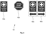
- the emergency alert 3 may be issued in the form of a displayable indication 42 projected on the ground and/or on at least one window of the motor vehicle 20.
- the displayable indication 42 may typically be a message, a sign or a pictogram that briefly and explicitly notify the emergency alert 3 to any person outside the motor vehicle 20.
- Fig. 5 provides some examples, of messages signs or pictograms such as "First Aid Needed” sign 42a and "Driver is not conscious” sign 42b, that may be projected on the ground or on the rear windshield of the motor vehicle 20 for example.
- a message or sign may be easily seen by any road users 31 such as persons within other vehicles and pedestrians, regardless the motor vehicle 20 displaying such an indication is moving or is stationary.
- the displayable indication 42 may also be projected on the ground, i.e. on the road or on the side of the road, for example using LED projectors embedded in the motor vehicle 20.
- LED projectors embedded in the motor vehicle 20.
- Such projectors may be located in the front of the motor vehicle 20, as head lamps, or below the doors which may include not only the side doors of the motor vehicle 20 but also the trunk door. Accordingly, these doors may not only be unlocked, but they may further be automatically opened by the emergency reaction system 10 in order to make the projection of the displayable indication 42 clearly visible on the ground, around the motor vehicle 20.
- the sign 42c shown in Fig. 5 may be projected on the right side of the motor vehicle 20 and the sign 42d on its left side.
- the appropriate sign 42c, 42d to be projected may also depends on which side of the road the motor vehicle 20 is stopped on, or if the sign is rather intended to be seen from the rear or the front of the motor vehicle 20.
- the call and/or the message 40 is issued to the emergency service 30 and/or to the support person 33, and the audible and/or visual indication 41 is notified to any vehicle occupant 21, preferably other vehicle occupant 32, and/or road user 31.
- the audible and/or visual indication 41 is preferably intended to any road user 31 and/or to any vehicle occupant 21, in particular to any other vehicle occupant 32
- the displayable indication 42 is preferably intended to any road user 31 and to the emergency service 30, for example to the paramedics of the emergency service 30.
- the health conditions 1 of the vehicle occupant 21 include at least one of the following elements:
- the emergency alert 3 includes information relating to the health conditions 1 of the vehicle occupant 21 whose health conditions 1 has reached the critical threshold 2. It means that the emergency alert 3 is not merely a warning sound or light, but includes and thus provides information regarding the emergency level of the vehicle occupant 21 who has caused the emergency alert 3.
- the information of the emergency alert 3 may specify that first aid is need, as a low urgency level, and may specify that the vehicle occupant 21 is unconscious as a high urgency level. Other information may be provided for intermediate levels, if any.
- the emergency alert 3 may include further information, such as specific information regarding parameters, values or other data of the health conditions 1 monitored by the physiological sensor(s) or monitoring device(s) 17.
- the information may include the heart rate, the blood pressure, the oxygen level, or any other physiological or behavioral parameters of the vehicle occupant 21.
- the information further includes a position 36, preferably the current position or the most recent known position 36, of the motor vehicle 20, especially if the emergency alert 3 is issued to at least one of:
- the position preferably the current position 36 or location of the motor vehicle 20, may be provided by a positioning device 37, such as a Global Positioning System (GPS), which may be connected to the emergency reaction system 10, e.g. via one of the communication interface such as the third interface 13, as shown in Fig. 1 .
- GPS Global Positioning System
- the positioning device 37 may be located within the emergency reaction system 10 and connected to an external antenna.
- the positioning device 37 may be based on a terrestrial radiolocation, i.e. on the radio signal(s) emitted by the mobile phone(s) of the vehicle occupant(s) 21.
- the radiolocation can be further based on trilateration between radio towers.
- the health conditions 1 of the vehicle occupants 21 are monitored as soon as the vehicle occupant 21 is aboard the motor vehicle 20 and/or as soon as the motor vehicle 20 is moving. Accordingly, the health conditions 1 of the vehicle occupant 21 can be advantageously kept up to date.
- Such an embodiment is schematically depicted by the two loops (one drawn in solid line and the other in dashed line) shown in Fig. 2 through the arrows which go back to the first step S1, respectively after the second step S2 and the fourth step S4.
- a monitoring may be based on a continuous or regular basis. Therefore, the information or at least of a part of the information included in the emergency alert 3 can be updated according to the most recent data provided by the monitoring operation performed at the first step S1.
- a new call 40 and/or a new sending message 40 is triggered if the health conditions 1 reach a second threshold, e.g. a second predefined threshold that is higher than the first one which has been denoted as the critical threshold 2.
- the present disclosure also relates to a non-transitory computer-readable medium 16 comprising program instructions for causing a processor, such as the controller 15 of Fig. 1 , to execute the method according to any of its embodiments or according to any possible combination of its embodiments.
- non-transitory does not exclude legitimate tangible temporary storage media such as flash drives or any rewritable storage media.
- a computer-accessible medium may include any tangible or non-transitory storage media or memory media such as electronic, magnetic, or optical media.
- Such a media may be a disk, a CD/DVD-ROM or any other medium which may coupled to the controller 15, e.g. via a dedicated communication interface or one of the already disclosed interfaces.
- such a media may located within the controller 15, e.g. in a permanent manner.
- tangible and “non-transitory,” as used herein, are intended to describe a computer-readable storage medium (or “memory”) excluding propagating electromagnetic signals, but are not intended to otherwise limit the type of physical computer-readable storage device that is encompassed by the phrase computer-readable medium or memory.
- non-transitory computer-readable medium or “tangible memory” are intended to encompass types of storage devices that do not necessarily store information permanently, including for example, random access memory (RAM) and flash memory.
- Program instructions and data stored on a tangible computer-accessible storage medium in non-transitory form may further be transmitted by transmission media or signals such as electrical, electromagnetic or digital signals.
- the present disclosure further relates to an emergency reaction system 10 for implementing the aforementioned method according to any of its embodiments or according to any possible combination of its embodiments. Since the emergency reaction system 10 has been already presented at the beginning of the detailed description and in connection with Fig. 1 , it appears as being not useful to provide further details on such a device.
- the present disclosure also relates to a motor vehicle 20 comprising at least the aforementioned emergency reaction system 10 according to any of its embodiments or possible combination of its embodiments.
Priority Applications (3)
| Application Number | Priority Date | Filing Date | Title |
|---|---|---|---|
| EP21168608.4A EP4074568A1 (de) | 2021-04-15 | 2021-04-15 | Verfahren zur ansteuerung eines notreaktionssystems |
| US17/659,110 US20220337696A1 (en) | 2021-04-15 | 2022-04-13 | Method for Driving an Emergency Reaction System |
| CN202210389811.XA CN115214718A (zh) | 2021-04-15 | 2022-04-14 | 驱动应急反应系统的方法 |
Applications Claiming Priority (1)
| Application Number | Priority Date | Filing Date | Title |
|---|---|---|---|
| EP21168608.4A EP4074568A1 (de) | 2021-04-15 | 2021-04-15 | Verfahren zur ansteuerung eines notreaktionssystems |
Publications (1)
| Publication Number | Publication Date |
|---|---|
| EP4074568A1 true EP4074568A1 (de) | 2022-10-19 |
Family
ID=75562537
Family Applications (1)
| Application Number | Title | Priority Date | Filing Date |
|---|---|---|---|
| EP21168608.4A Pending EP4074568A1 (de) | 2021-04-15 | 2021-04-15 | Verfahren zur ansteuerung eines notreaktionssystems |
Country Status (3)
| Country | Link |
|---|---|
| US (1) | US20220337696A1 (de) |
| EP (1) | EP4074568A1 (de) |
| CN (1) | CN115214718A (de) |
Cited By (1)
| Publication number | Priority date | Publication date | Assignee | Title |
|---|---|---|---|---|
| US11718327B1 (en) * | 2022-08-08 | 2023-08-08 | Toyota Motor Engineering & Manufacturing North America, Inc. | Systems and methods for operating a vehicle based on a user's health and emotional state |
Citations (4)
| Publication number | Priority date | Publication date | Assignee | Title |
|---|---|---|---|---|
| WO2000020258A1 (en) * | 1998-10-01 | 2000-04-13 | Biosys Ab | A method and an apparatus for monitoring a seated person |
| DE102015105581A1 (de) * | 2014-11-03 | 2016-05-04 | Audi Ag | System und Verfahren zur Überwachung des Gesundheitszustandes und/oder des Befindens eines Fahrzeuginsassen |
| KR20180108263A (ko) * | 2017-03-24 | 2018-10-04 | 주식회사 핸디소프트 | 센서 기반의 운전자 및 차량 비상 상황 외부 알림 시스템 및 방법 |
| US20200317210A1 (en) * | 2019-04-03 | 2020-10-08 | Industrial Technology Research Institute | Driving assistance system and driving assistance method |
-
2021
- 2021-04-15 EP EP21168608.4A patent/EP4074568A1/de active Pending
-
2022
- 2022-04-13 US US17/659,110 patent/US20220337696A1/en active Pending
- 2022-04-14 CN CN202210389811.XA patent/CN115214718A/zh active Pending
Patent Citations (4)
| Publication number | Priority date | Publication date | Assignee | Title |
|---|---|---|---|---|
| WO2000020258A1 (en) * | 1998-10-01 | 2000-04-13 | Biosys Ab | A method and an apparatus for monitoring a seated person |
| DE102015105581A1 (de) * | 2014-11-03 | 2016-05-04 | Audi Ag | System und Verfahren zur Überwachung des Gesundheitszustandes und/oder des Befindens eines Fahrzeuginsassen |
| KR20180108263A (ko) * | 2017-03-24 | 2018-10-04 | 주식회사 핸디소프트 | 센서 기반의 운전자 및 차량 비상 상황 외부 알림 시스템 및 방법 |
| US20200317210A1 (en) * | 2019-04-03 | 2020-10-08 | Industrial Technology Research Institute | Driving assistance system and driving assistance method |
Non-Patent Citations (2)
| Title |
|---|
| MICHAELA SIDIKOVA ET AL., VITAL SIGN MONITORING IN CAR SEATS BASED ON ELECTROCARDIOGRAPHY, BALLISTOCARDIOGRAPHY AND SEISMOCARDIOGRAPHY: A REVIEW, October 2020 (2020-10-01) |
| STEFFEN LEONHARDT ET AL., UNOBTRUSIVE VITAL SIGN MONITORING IN AUTOMOTIVE ENVIRONMENTS - A REVIEW, 13 September 2018 (2018-09-13) |
Cited By (1)
| Publication number | Priority date | Publication date | Assignee | Title |
|---|---|---|---|---|
| US11718327B1 (en) * | 2022-08-08 | 2023-08-08 | Toyota Motor Engineering & Manufacturing North America, Inc. | Systems and methods for operating a vehicle based on a user's health and emotional state |
Also Published As
| Publication number | Publication date |
|---|---|
| US20220337696A1 (en) | 2022-10-20 |
| CN115214718A (zh) | 2022-10-21 |
Similar Documents
| Publication | Publication Date | Title |
|---|---|---|
| US10647252B2 (en) | Portable electronic device and operating method therefor | |
| JP4191313B2 (ja) | 事故抑止装置 | |
| US20210086778A1 (en) | In-vehicle emergency detection and response handling | |
| KR101499508B1 (ko) | 사고 유형 감지 및 사고 처리를 수행하는 차량용 영상기록 장치와 그 제어방법 | |
| RU151784U1 (ru) | Устройство уведомления водителя, покидающего остановленный автомобиль, если в автомобиле находится еще одно лицо или животное | |
| WO2017086079A1 (ja) | 自動運転支援装置、自動運転支援システム、自動運転支援方法および自動運転支援プログラム | |
| CN103978977A (zh) | 基于人体通信的汽车监控系统和方法 | |
| US10198952B2 (en) | Operator alertness monitor | |
| CN110291479B (zh) | 一种基于瞬时自主操作情境执行回退操作的方法及车辆 | |
| US20080004774A1 (en) | System and method for child safety in a vehicle | |
| US11104346B2 (en) | Autonomous vehicle control system and autonomous vehicle control method using the same | |
| US10829130B2 (en) | Automated driver assistance system | |
| JP2009075695A (ja) | 危険報知装置およびシステム | |
| US20220337696A1 (en) | Method for Driving an Emergency Reaction System | |
| CN203195771U (zh) | 一种车载急救辅助装置 | |
| JP2018055446A (ja) | 車両運行管理システム | |
| US20210064029A1 (en) | Autonomous safe stop feature for a vehicle | |
| JP2018055445A (ja) | 車両運行管理システム | |
| JP2023182752A (ja) | システムおよびプログラム等 | |
| SE539493C2 (sv) | Förarvarning och begränsning av fordons framförande vid olyckstillbud | |
| JP2016085730A (ja) | 車両用データ記録装置及び車両用事故通報装置 | |
| US11433916B1 (en) | System to generate an alert to wake a driver of a vehicle and a method thereof | |
| JP2005044060A (ja) | 緊急通報システム | |
| CN114496181A (zh) | 车辆中的自动分诊护士系统 | |
| CN114572141A (zh) | 乘员监测系统、乘员遗留提醒方法及相关设备 |
Legal Events
| Date | Code | Title | Description |
|---|---|---|---|
| PUAI | Public reference made under article 153(3) epc to a published international application that has entered the european phase |
Free format text: ORIGINAL CODE: 0009012 |
|
| STAA | Information on the status of an ep patent application or granted ep patent |
Free format text: STATUS: THE APPLICATION HAS BEEN PUBLISHED |
|
| AK | Designated contracting states |
Kind code of ref document: A1 Designated state(s): AL AT BE BG CH CY CZ DE DK EE ES FI FR GB GR HR HU IE IS IT LI LT LU LV MC MK MT NL NO PL PT RO RS SE SI SK SM TR |
|
| RAP3 | Party data changed (applicant data changed or rights of an application transferred) |
Owner name: APTIV TECHNOLOGIES LIMITED |
|
| STAA | Information on the status of an ep patent application or granted ep patent |
Free format text: STATUS: REQUEST FOR EXAMINATION WAS MADE |
|
| 17P | Request for examination filed |
Effective date: 20230403 |
|
| RBV | Designated contracting states (corrected) |
Designated state(s): AL AT BE BG CH CY CZ DE DK EE ES FI FR GB GR HR HU IE IS IT LI LT LU LV MC MK MT NL NO PL PT RO RS SE SI SK SM TR |
|
| RAP1 | Party data changed (applicant data changed or rights of an application transferred) |
Owner name: APTIV TECHNOLOGIES AG |