EP4073507B1 - Kohlenstoffmessungen in wässrigen proben mittels oxidation bei erhöhten temperaturen und drücken durch widerstandserwärmung - Google Patents
Kohlenstoffmessungen in wässrigen proben mittels oxidation bei erhöhten temperaturen und drücken durch widerstandserwärmung Download PDFInfo
- Publication number
- EP4073507B1 EP4073507B1 EP19838993.4A EP19838993A EP4073507B1 EP 4073507 B1 EP4073507 B1 EP 4073507B1 EP 19838993 A EP19838993 A EP 19838993A EP 4073507 B1 EP4073507 B1 EP 4073507B1
- Authority
- EP
- European Patent Office
- Prior art keywords
- reactor
- interior
- sample
- sensor
- electrical current
- Prior art date
- Legal status (The legal status is an assumption and is not a legal conclusion. Google has not performed a legal analysis and makes no representation as to the accuracy of the status listed.)
- Active
Links
Images


Classifications
-
- G—PHYSICS
- G01—MEASURING; TESTING
- G01N—INVESTIGATING OR ANALYSING MATERIALS BY DETERMINING THEIR CHEMICAL OR PHYSICAL PROPERTIES
- G01N33/00—Investigating or analysing materials by specific methods not covered by groups G01N1/00 - G01N31/00
- G01N33/18—Water
- G01N33/1826—Organic contamination in water
- G01N33/1846—Total carbon analysis
-
- G—PHYSICS
- G01—MEASURING; TESTING
- G01N—INVESTIGATING OR ANALYSING MATERIALS BY DETERMINING THEIR CHEMICAL OR PHYSICAL PROPERTIES
- G01N21/00—Investigating or analysing materials by the use of optical means, i.e. using sub-millimetre waves, infrared, visible or ultraviolet light
- G01N21/17—Systems in which incident light is modified in accordance with the properties of the material investigated
- G01N21/25—Colour; Spectral properties, i.e. comparison of effect of material on the light at two or more different wavelengths or wavelength bands
- G01N21/31—Investigating relative effect of material at wavelengths characteristic of specific elements or molecules, e.g. atomic absorption spectrometry
- G01N21/35—Investigating relative effect of material at wavelengths characteristic of specific elements or molecules, e.g. atomic absorption spectrometry using infrared light
- G01N21/3504—Investigating relative effect of material at wavelengths characteristic of specific elements or molecules, e.g. atomic absorption spectrometry using infrared light for analysing gases, e.g. multi-gas analysis
-
- B—PERFORMING OPERATIONS; TRANSPORTING
- B01—PHYSICAL OR CHEMICAL PROCESSES OR APPARATUS IN GENERAL
- B01L—CHEMICAL OR PHYSICAL LABORATORY APPARATUS FOR GENERAL USE
- B01L3/00—Containers or dishes for laboratory use, e.g. laboratory glassware; Droppers
- B01L3/50—Containers for the purpose of retaining a material to be analysed, e.g. test tubes
- B01L3/502—Containers for the purpose of retaining a material to be analysed, e.g. test tubes with fluid transport, e.g. in multi-compartment structures
- B01L3/5027—Containers for the purpose of retaining a material to be analysed, e.g. test tubes with fluid transport, e.g. in multi-compartment structures by integrated microfluidic structures, i.e. dimensions of channels and chambers are such that surface tension forces are important, e.g. lab-on-a-chip
- B01L3/502715—Containers for the purpose of retaining a material to be analysed, e.g. test tubes with fluid transport, e.g. in multi-compartment structures by integrated microfluidic structures, i.e. dimensions of channels and chambers are such that surface tension forces are important, e.g. lab-on-a-chip characterised by interfacing components, e.g. fluidic, electrical, optical or mechanical interfaces
-
- G—PHYSICS
- G01—MEASURING; TESTING
- G01N—INVESTIGATING OR ANALYSING MATERIALS BY DETERMINING THEIR CHEMICAL OR PHYSICAL PROPERTIES
- G01N1/00—Sampling; Preparing specimens for investigation
- G01N1/28—Preparing specimens for investigation including physical details of (bio-)chemical methods covered elsewhere, e.g. G01N33/50, C12Q
- G01N1/42—Low-temperature sample treatment, e.g. cryofixation
-
- G—PHYSICS
- G01—MEASURING; TESTING
- G01N—INVESTIGATING OR ANALYSING MATERIALS BY DETERMINING THEIR CHEMICAL OR PHYSICAL PROPERTIES
- G01N1/00—Sampling; Preparing specimens for investigation
- G01N1/28—Preparing specimens for investigation including physical details of (bio-)chemical methods covered elsewhere, e.g. G01N33/50, C12Q
- G01N1/44—Sample treatment involving radiation, e.g. heat
-
- G—PHYSICS
- G01—MEASURING; TESTING
- G01N—INVESTIGATING OR ANALYSING MATERIALS BY DETERMINING THEIR CHEMICAL OR PHYSICAL PROPERTIES
- G01N33/00—Investigating or analysing materials by specific methods not covered by groups G01N1/00 - G01N31/00
- G01N33/0004—Gaseous mixtures, e.g. polluted air
- G01N33/0009—General constructional details of gas analysers, e.g. portable test equipment
- G01N33/0027—General constructional details of gas analysers, e.g. portable test equipment concerning the detector
- G01N33/0036—General constructional details of gas analysers, e.g. portable test equipment concerning the detector specially adapted to detect a particular component
- G01N33/004—CO or CO2
-
- G—PHYSICS
- G05—CONTROLLING; REGULATING
- G05D—SYSTEMS FOR CONTROLLING OR REGULATING NON-ELECTRIC VARIABLES
- G05D23/00—Control of temperature
- G05D23/19—Control of temperature characterised by the use of electric means
- G05D23/27—Control of temperature characterised by the use of electric means with sensing element responsive to radiation
-
- B—PERFORMING OPERATIONS; TRANSPORTING
- B01—PHYSICAL OR CHEMICAL PROCESSES OR APPARATUS IN GENERAL
- B01L—CHEMICAL OR PHYSICAL LABORATORY APPARATUS FOR GENERAL USE
- B01L2300/00—Additional constructional details
- B01L2300/06—Auxiliary integrated devices, integrated components
- B01L2300/0627—Sensor or part of a sensor is integrated
- B01L2300/0663—Whole sensors
-
- B—PERFORMING OPERATIONS; TRANSPORTING
- B01—PHYSICAL OR CHEMICAL PROCESSES OR APPARATUS IN GENERAL
- B01L—CHEMICAL OR PHYSICAL LABORATORY APPARATUS FOR GENERAL USE
- B01L2300/00—Additional constructional details
- B01L2300/18—Means for temperature control
- B01L2300/1833—Means for temperature control using electrical currents in the sample itself
-
- B—PERFORMING OPERATIONS; TRANSPORTING
- B01—PHYSICAL OR CHEMICAL PROCESSES OR APPARATUS IN GENERAL
- B01L—CHEMICAL OR PHYSICAL LABORATORY APPARATUS FOR GENERAL USE
- B01L2300/00—Additional constructional details
- B01L2300/18—Means for temperature control
- B01L2300/1894—Cooling means; Cryo cooling
-
- B—PERFORMING OPERATIONS; TRANSPORTING
- B01—PHYSICAL OR CHEMICAL PROCESSES OR APPARATUS IN GENERAL
- B01L—CHEMICAL OR PHYSICAL LABORATORY APPARATUS FOR GENERAL USE
- B01L2400/00—Moving or stopping fluids
- B01L2400/06—Valves, specific forms thereof
- B01L2400/0633—Valves, specific forms thereof with moving parts
Definitions
- the embodiments described herein generally relate to methods and apparatus for making very precise, reliable and reproducible measurements of concentrations of organic, inorganic and total carbon present in aqueous samples.
- Such methods and apparatus may be used, for example, to determine the concentration of total organic carbon (TOC) in drinking water, raw water, wastewater, industrial process streams and the like.
- TOC total organic carbon
- Such measurement may be utilized for various important commercial purposes, for example to optimize water purification processes, to detect spills, and to monitor compliance with environmental regulations.
- the methods and apparatus described herein can generally be applied both to measuring discrete aqueous samples, such as those encountered in a laboratory environment, and to monitoring flowing streams to provide real-time concentration data.
- Total organic carbon is a well-established water quality parameter that quantifies the overall concentration of organic substances, all of which are typically regarded as contaminants, in an aqueous environment.
- Total organic carbon in an aqueous sample may be composed of either one or two components-dissolved organic carbon (DOC) and particulate organic carbon.
- DOC components-dissolved organic carbon
- the measurement of DOC is conventionally accomplished by filtering the water sample, commonly through a 0.45- ⁇ m filter, to remove particulate organic carbon prior to performing an analysis for DOC.
- the limitations of conventional apparatus and techniques for Such analysis often lead to the result that only DOC is effectively measured, instead of TOC, because the particulates in a sample containing both forms of organic carbon typically cause errors in the measurement and plug fluid passages causing hardware failures.
- DOC is used to refer to measurements in which the sample has first been filtered to remove particulates
- TOC is used herein to refer to measurements in which the sample has not been filtered. In other respects, however, the following description is relevant to both DOC and TOC measurements.
- the organic compounds in an aqueous sample are oxidized to carbon dioxide (CO 2 ) and the CO 2 in the sample is then measured.
- the water sample may initially contain CO 2 and other inorganic forms of carbon (e.g., in the form of bicarbonate and carbonate salts). Together, these forms of inorganic carbon are referred to herein as IC.
- Total carbon (TC) concentration in an aqueous sample is therefore the sum of the TOC and IC concentrations.
- the measurement of total organic carbon in a sample relies on the conversion of organic carbon to carbon dioxide.
- the more common methods have been high temperature combustion, vaporizing the sample and heating the gas to over 600C. Air or oxygen is used to react with the organics at high temperature to accomplish the conversion of organic carbon to carbon dioxide.
- the other common method has been to mix the liquid sample an oxidizing agent such as persulfate and then activate the persulfate with heat or ultraviolet radiation. The activated persulfate will convert the organic carbon to carbon dioxide. After conversion the carbon dioxide is measured and the amount of organic carbon is calculated based on the amount of carbon dioxide measured.
- a reactor heater element has a tubular configuration open at both ends and located inside a heater housing with the reactor mounted inside the tubular portion of the heater.
- the methods and apparatus described herein are capable of measuring all of the aforementioned parameters in samples that contain concentrations of TOC, dissolved solids, and particulates.
- a sample is drawn into the analyzer described herein, reagents are added, and the sample is diluted as necessary, and then the sample enters the oxidation reactor where super critical water oxidation is used to effect the conversion of organic carbon to carbon dioxide.
- the critical point of water is 374C and 3200psia. To reach these temperatures and pressures the water sample is trapped in the reactor with a small amount of air and oxidizing agent. Because it is a closed system the pressure inside the tube reaches the critical point. Under these conditions organics as well as organic particles are converted to carbon dioxide.
- the present disclosure relates to an apparatus for treating a liquid sample containing organic material.
- the device includes: (a) a reactor having reactor inlet and reactor outlet ports and a reactor interior for containing a liquid sample under above-ambient temperature and pressure conditions; (b) high pressure fluid reactor valve members at said reactor inlet and reactor outlet ports, said reactor valve members allowing fluid flow respectively into or out of the reactor interior when in an open-valve mode or, alternatively, capable of sealing the reactor interior when in a closed-valve mode; (c) a reactor heating system including an electrical current source operably connected to the reactor, the electrical current source configured to pass an electrical current through the reactor to rapidly and cyclically heat the reactor interior and a liquid sample sealed in the reactor interior to a temperature of about 150° C. to 650° C. or higher, while the reactor interior and the reactor valve members maintain the sample under sealed conditions; and, (d) a reactor cooling system adapted for rapidly and cyclically cooling the reactor interior and a reactor product sealed in the reactor interior following a heating cycle.
- a sensor is configured to determine a temperature value of the reactor.
- the senor is configured to measure electromagnetic radiation.
- the senor is operably connected to the reactor heating system.
- the senor is operably connected to the reactor cooling system.
- the reactor is comprised of titanium and its alloys, tantalum, Inconel 625, Hastelloy C-276, or combinations thereof.
- a reactor cooling system adapted for rapidly and cyclically cooling the reactor interior and a reactor product sealed in the reactor interior following a heating cycle.; (b) mixing a known volume of the sample with one or more other liquids selected from oxidizer, acid and dilution water to form a sample mixture; (c) flowing at least a portion of the sample mixture into the interior of the reactor, said reactor being adapted to be alternately and repeatedly opened and sealed at the reactor inlet and reactor outlet ports; (d) sealing the portion of sample mixture in the interior of the reactor by closing the valve members at the reactor inlet and reactor outlet ports; (e) passing an electrical current through the reactor for a time sufficient substantially to oxidize the organic material and form the reactor product; (f) stopping the heating step and then rapidly cooling the interior of the reactor and the reactor product inside to substantially ambient conditions to form cooled liquid and gaseous reactor products; and, (g) opening the reactor and removing the
- the interior of the reactor and the sample portion inside is rapidly heated to a temperature between 150° C. to about 650° C.
- a sensor configured to measure a temperature value of the reactor.
- the senor is configured to measure electromagnetic radiation.
- the senor is configured to measure infrared radiation.
- the reactor is comprised of titanium and its alloys, tantalum, Inconel 625, Hastelloy C-276, or combinations thereof.
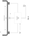
- FIG. 1 is a block schematic of one embodiment of an automated carbon measurement apparatus/analyzer illustrating five component sub-assemblies 1 to 5 that comprise the analyzer.
- an aqueous sample is drawn into a sample handling sub-assembly 1 of the apparatus, where the desired volumes of acid reagent and/or oxidizer reagent are added to a selected volume of sample.
- the sample may also be diluted at this stage with low-TOC dilution water if necessary before being passed to reactor sub-assembly 3. Additional details about the shown and described measurement apparatus/analyzer can be found in U.S. Patent Nos.
- the sample, reagents and dilution water if any are mixed in the sample-handling portions of the apparatus to create a sample mixture comprising a substantially homogenous solution or suspension. If NPOC is to be measured, the acidified sample mixture also is sparged with CO 2 -free gas provided by the gas control sub-assembly/module 2. The flow rate of the sparge gas is controlled to ensure that IC in the sample is removed efficiently and substantially completely. If TC or IC is to be measured, the sample mixture is mixed but not sparged.
- a portion of the homogenous solution/suspension is then transferred to the reactor sub-assembly 3.
- the solution/suspension containing oxidizer is heated in a sealed reactor to oxidize the organic compounds in the solution/suspension, and then it is cooled to near room temperature.
- oxidizer is not added to the solution/suspension. In this case, the solution/suspension may be warmed to facilitate conversion of bicarbonates and carbonates to CO 2 ., but it is not heated so much that oxidation of organic compounds occurs.
- a stream of carrier gas from the gas control assembly/ module 2 transfers the liquid and gas products in the reactor sub-assembly 3 to a gas/liquid separator sub-assembly/module 4.
- the liquid exits the analyzer from the gas/liquid separator module 4 while the gas product, containing the CO 2 , flows to the NDIR detector sub-assembly 5.
- the gas product and carrier gas mixture can be flowed through the gas/liquid separator module 4, and vented to the atmosphere.
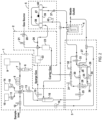
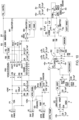
- FIG. 2 is a schematic showing the several fluidic components of an embodiment of the apparatus in more detail.
- sub-assemblies 1 to 5 as shown in FIG. 1 are delineated by broken lines.
- the sample-handling sub-assembly 1 comprises a syringe 6 that is connected through a three-way valve 7 to a coil of tubing 8 and a dilution water reservoir 9 containing low-TOC dilution water.
- a representative practice using the apparatus as illustrated in FIG. 2 is described below. It will be understood, however, that alternative sequences and methods for introducing the sample, reagent(s) and dilution water into the system could be used consistent with the scope of this invention.
- the oxidizer and acid reagents could be moved from coil 8 to a mixing location in the apparatus, such as to mixer/sparger 18, prior to introducing the sample into the system in order to maintain a separation between these components until they are ready to be mixed at the mixing location.
- the syringe is empty, and the valve 7 and coil 8 contain only dilution water.
- the volume of coil 8 is designed and selected to be at least as large as, and preferably larger than, the volume of syringe 6, so the only liquid that can enter the syringe is dilution water from coil 8 or reservoir 9.
- valve 10 is open, and valves 11, 12, and 13 are closed.
- Syringe 6 starts filling with dilution water drawn from a syringe end of coil 8, which causes oxidizer reagent from oxidizer reagent reservoir 14 to be drawn through the six-way fluid element 17 and into a sample/reagent end of coil 8.
- valve 10 closes.
- Valve 11 opens and syringe 6 draws additional dilution water from the y syringe end of coil 8 into syringe 6, which in turn draws the required volume of acid from acid reservoir 15 into the sample/reagent end of coil 8, where it may partially mix with the oxidizer reagent already in this end of coil 8.
- the syringe 6 stops momentarily, valve 11 closes, and valve 12 opens to allow the required volume of sample to be drawn into the sample/reagent end of coil 8, as additional dilution water from the syringe end of coil 8 is drawn into syringe 6.
- valve 12 closes.
- the coil 8 now contains the desired volumes of oxidizer, acid, and sample solution required for the measurement.
- Coil 8 may or may not contain a material amount of dilution water at this point, depending on the internal volume of coil 8 relative to the volumes of oxidizer, acid and sample drawn into coil 8, and also depending upon whether or not the sample requires dilution prior to analysis.
- the source of the sample is a long distance from the analyzer, especially when embodiments of the analyzer described herein is used to monitor a process stream of an industrial operation.
- the analyzer may not provide real-time measurements if the only way of pumping the sample to the analyzer were the syringe pump. Therefore, in one of the embodiments described herein, the apparatus also includes a pump 16 which can rapidly draw a fresh portion of sample to the six-way union 17. Once the new sample portion has been delivered to element 17, it can be drawn into coil 8 quickly by further opening syringe 6 at the appropriate time.
- valve 13 With valve 13 open, the step of closing syringe 6 results in moving the liquids from coil 8 to a mixing location in the system, such as to the mixer/sparger component 18, where the reagents, sample, and dilution water, if any, are thoroughly mixed. Particulate material in the sample is kept in suspension so that the solution/suspension is substantially homogeneous.
- the acid and oxidizer are first drawn into coil 8 and then are transferred into mixing/sparging chamber 18.
- the sample and dilution water (if any) are then drawn into coil 8 and transferred into mixing/sparging chamber 18 where the sample, acid, oxidizer, and dilution water are mixed.
- Transferring the liquids to the mixing/sparging chamber 18 in two steps has the advantage of preventing premature reaction of IC in the sample with the acidic reagents in coil 8.
- Generation of gas in coil 8 reduces the volume of sample drawn into coil 8, adversely affecting the accuracy of the measurement.
- Mixer/sparger 18 includes a mixing and sparging chamber that also is designed to provide for sparging CO 2 -free gas through the solution/suspension to remove IC, if NPOC is to be measured.
- valve 19 opens to allow the sparge gas to bubble through the chamber element of mixer/sparger 18.
- the gas can be provided from a pressurized gas cylinder (not shown) or from a pump (not shown) that draws ambient air through an absorber that purifies the air sufficiently for use as a CO 2 -free sparge gas, and/or as a carrier gas, and/or as a purge gas.
- the CO 2 -free gas is prepared for use in gas control sub-assembly module 2.
- Sub-assembly 2 includes a pressure-regulating device 20 that adjusts the pressure of the gas to about 20 psig.
- a proportioning valve 21 controls the flow rate of the gas flowing through valve 19 by means of a sparge gas flow sensor 22.
- a carrier gas flow sensor 23 in another conduit branch can be used to monitor and control the flow rate of the carrier gas to reactor sub-assembly 3.
- a restrictor 24 in still another conduit branch can be used to provide for a small flow rate of purge gas to the NDIR detector.
- a valve (not shown) can be used to direct the gas that exits the chamber element of mixer/sparger 18 through the gas/liquid separator unit 4 and then to the NDIR sub-assembly 5. This arrangement would allow the completeness of the sparging process to be monitored. Thus, the sparging is considered complete when the NDIR indicates that the concentration of CO 2 in the sparge gas going to the NDIR has decreased to a very small (negligible) value.
- valve 25 opens to allow all or a portion of the solution/suspension in the chamber element to be drawn into the interior of reactor 26 by pump 27.
- High-pressure reactor inlet and outlet valves 28 and 29 respectively are open at this point. Valves 30, 31, 32, and 33 are closed. The reactor heater 34 is off, and reactor 26 is near ambient temperature.
- Pump 27 operates until sufficient liquid from chamber 18 has passed through the interior of reactor 26 Substantially to rinse out any remaining prior sample and to fill the reactor tube inside reactor 26. At this point, pump 27 is stopped, and valves 25, 28, and 29 close.
- Reactor valves 28 and 29 allow the valve housings to be flushed after these valves are closed.
- the flushing step removes excess sample that contains CO 2 formed by the acidification of the IC in the sample. If this CO 2 were not flushed out of the valves, it would cause an error in the subsequent measurement.
- valves 30 and 31 are opened, and residual liquid and gases in these housings can then be pumped out by pump 27 and replaced by carrier gas.
- valve 31 closes and valve 32 opens to allow carrier gas to flow from sub-assembly 3 through valve 32, pass through the gas/liquid separator 4, and then pass to the NDIR detector sub-assembly 5. Flow of carrier gas at this time is necessary to allow the NDIR detector to reach a steady baseline prior to the subsequent CO 2 measurement.
- An in-line filter 37 may be provided between gas/liquid separator 4 and the NDIR unit to prevent aerosols from the reactor 26 and/or from gas/liquid separator 4 from entering the optical path 39 of the NDIR detector.
- the organics contained in the sample portion in the reactor tube of reactor 26 must be oxidized.
- This oxidation can be made to occur by heating the interior of reactor 26 with a heater 34, and/or by resistive heating as described herein, while controlling the temperature using a temperature sensor 35.
- the sealed reactor can be heated, for example, to a temperature between about 150° C. and 650° C. (preferably between about 300° C. and 400° C., and between about 350° C. and 390° C. in one embodiment).
- the heating period may be between about one to thirty minutes, preferably between about two and four minutes, and approximately 3 minutes in one embodiment. During this period, organics are oxidized in the sample portion in the reactor.
- heating element 34 is turned off, and fan unit 36 is turned on to blow ambient air over reactor 26, cooling it rapidly to near room temperature. Because of the small mass of reactor 26, it is typically cooled by this cooling step to near ambient temperature in less than about 90 seconds.
- the liquid inside reactor 26 is not oxidized.
- the reactor is filled as described above, but reactor 26 is heated only to a temperature sufficient to facilitate formation of CO2 from bicarbonates and carbonates (i.e., typically to no more than about 100°C.).
- the subsequent cooling step may in this case be abbreviated or omitted entirely.
- the oxidizer reagent is not required for IC measurements, and its addition to the sample prior to the reactor step can thus be omitted to reduce operating cost and make the analysis faster.
- Valves 30 and 32 close, and valves 28, 29, 31, and 33 open.
- This apparatus configuration allows carrier gas to flow through the reactor tube of reactor 26, and carry the reactor products through gas/liquid separator 4, to the NDIR sub-assembly and along the NDIR optical path 39.
- the NDIR measures the absorbance of the CO 2 in the gas flowing along NDIR optical path 39 at a wavelength of approximately 4.26 ⁇ m, e.g., 4.26 ⁇ m ⁇ 0.2 ⁇ m.
- the absorbance measurement begins at a baseline level, rises up to and passes through a maximum level, and then returns to the baseline level that existed before the valves associated with reactor 26 opened.
- Either the height of the absorbance peak (or the depth of the intensity trough) or the cone-shaped area of the absorbance response curve can be calibrated and used to determine the amount of CO 2 contained in the gas product coming from the reactor.
- the NDIR detector is comprised of three chambers, as seen in FIGS. 2 and 6 .
- One chamber 38 contains the IR source.
- the central chamber which is the NDIR optical path 39, is the chamber through which the carrier gas and the gas product from reactor 26 (which includes the CO 2 ) flow.
- the third chamber 40 contains the IR detector. Chambers 38 and 40 are flushed by CO 2 -free gas provided through the conduit that includes flow controller 24 so that CO 2 in the ambient air does not affect the measurements made with the NDIR.
- the NDIR further includes an associated temperature sensor 41 and an associated pressure sensor 42. proximately located relative to the NDIR, which monitors atmospheric pressure outside the NDIR (which is essentially the same as the pressure of the CO 2 in the NDIR).
- temperature sensor 41 and pressure sensor 42 can be used to compensate the response of the NDIR for variations in the temperature and pressure of the gas being measured.
- sensors 41 and/or 42 may be omitted if the measurement does not require temperature and/or pressure compensation.
- the mixer/sparger includes a liquid inlet/gas outlet section 43, a middle section 44, and a liquid outlet/gas inlet section 45.
- the top section 43 contains a liquid inlet 43a and the Sparge gas outlet 43b.
- the bottom section 45 includes the inlet port 45b for the sparge gas and the outlet 45a for liquid.
- the middle section 44 includes a chamber element 44a located inside an annular solenoid coil 44b, which is activated by passing a series of current pulses through it.
- Such current waveform pulsing causes a magnetic stirrer 46 positioned inside chamber 44a to rapidly move up and down inside chamber 44a.
- the magnetic stirrer 46 is coated with a corrosion-resistant outer layer, and its up-and-down action under the influence of the solenoid-generated waveform pulses causes the sample, reagents and dilution water, if any, inside chamber 44a to be rapidly mixed, typically in about 60 seconds or less.
- the bottom section 45 of mixer/sparger 18 includes a porous gas disperser 47, through which sparge gas is directed on its way into chamber 44a.
- the pore diameter in the gas disperser 47 may be about 1 ⁇ m to 0.125 in., e.g., preferably about 5 ⁇ m to 50 ⁇ m, and about 18 ⁇ m in one embodiment.
- the small bubbles produced by passing the sparge gas through disperser 47 results in efficient removal of IC from the liquid in chamber 44a, generally in about 10 seconds to 20 minutes at sparge gas flow rates ranging from about 50 to about 500 cc/min., typically and preferably in about one minute or less at a sparge gas flow rate of about 200 cc/min.
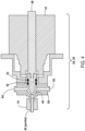
- a polymeric or elastic Seal 48 is attached to or comprises a front end or section of a moveable plunger element 49, which is designed to move back and forth inside the housing/valve body 50 when motor 51 is activated.
- the rear portion of seal 48 is adapted to retain first and second O-rings 52 and 53 respectively, which seal the interior of housing 50.
- the front end of seal 48 is sized and shaped to mate with and plug an opening (i.e., an inlet opening or an outlet opening) of reactor 26 when the valve is closed by advancing plunger element 49.
- Reactor 26 may be attached to valve housings 50, for example, using fittings 70 (as seen in FIG. 4 ), which provide a seal that is essentially leak-free at the pressure produced in reactor 26 when the solution/suspension is sealed inside reactor 26, and reactor 26 is heated.
- Seal 48 is enclosed by a seal chamber defined by the valve housing 50 extending from the sealed opening of reactor 26 at least to first O-ring 52.
- This chamber can be continuously or periodically flushed with gas using seal chamber ports 54 and 55 as shown in FIG. 4 .
- Reactor valves 28 and 29 also each have a third port that is not seen in FIG. 4 .
- the sample solution/suspension enters or exits the valve and the interior of reactor 26 through that third port.
- This apparatus configuration makes it possible to remove any IC or free CO 2 that may be present in the valve housing 50 while the sample is being oxidized/treated in reactor 26.
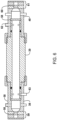
- FIG. 5 is a schematic illustration of reactor valves 28 and 29 mounted at either end of a reactor 26.
- the reactor heater element 34 has a tubular configuration open at both ends and located inside a heater housing with the reactor 26 mounted inside the tubular portion of heater 34.
- heater 34 comprises a thick-film heating element deposited on an electrically insulating coating on the tubular portion of heater 34, as shown in FIG. 5 .
- the tubular portion of heater 34 may be constructed of stainless steel, titanium, or other suitable materials.
- the two ends of reactor 26 pass respectively through slots (not shown in FIG. 5 ) in the sidewall of the tubular portion of heater 34.
- reactor 26 is a tube generally constructed of titanium; however, stainless steel, ceramics, and other materials that are sufficiently corrosion resistant and compatible with the oxidation temperatures required can be used including titanium and its alloys grade 7 and grade 7H, tantalum, Inconel 625, Hastelloy C-276, and the like.
- the reactor assembly may also include a fan component to cool the reactor 26 after a heating/oxidation step. As seen in FIG.
- the outlet (downstream side) of fan 36 may be positioned close to one open end of the heater 34, and is oriented so that a flow of cooling air during a cooling step passes through the heater housing and over both the exterior and interior of heater 34, and also such that the airflow going through the interior of the tubular portion of the heater 34 during a cooling step passes over the portion of reactor 26 contained within the tubular portion of heater 34.
- the NDIR detector sub-assembly 5 is shown in greater detail in FIG. 6 .
- the NDIR consists of an optical system and an associated NDIR electronic system (as illustrated in the block diagram of FIG. 7 ).
- the NDIR optical system generally has three sections: an IR source compartment 38, a sample cell/NDIR optical path 39, and an IR detector compartment 40.
- Collimating lenses 58 located at either end of sample cell 39 separate the adjacent sections.
- the lenses 58 are constructed of silicon.
- the IR source 56 is a thin-film heater. It may be mounted in plates 59 that are attached to an IR source heater and an IR source temperature sensor. Using the associated NDIR electronic system, the plates 59 and IR source 56 are controlled to a temperature of about 65° C. in one embodiment.
- the IR detector 60 is a pyro electric, lithium tantalate sensor element.
- a 4.26 ⁇ m filter is mounted in the IR detector in front of the sensor element. This filter selectively passes infrared radiation at the wavelength that is absorbed by CO 2 .
- the IR detector 60 measures the IR radiation that passes through the optical path39 and the filter without being absorbed by CO 2 .
- the IR detector 60 may be mounted in plates 61 attached to an IR detector heater and an IR detector temperature sensor. In one embodiment, the IR detector 60 is controlled at a temperature of about 55° C. using the associated NDIR electronic system.
- Carrier gas and the gas product from reactor 26, including the CO 2 flow through the center section 39 of the NDIR.
- IR source 56 and IR detector 60 located in their separate compartments, are isolated from water vapor and potentially corrosive oxidation products by the compartment separation lenses 58.
- the chambers 38 and 40 are also sealed, and CO 2 from ambient air is prevented from entering, or at least from remaining in, those chambers by flowing purge gas provided by the gas control sub-assembly 2.
- the center section 39 of the NDIR has a gas inlet port 62 and a gas outlet port 63, through which the carrier gas and the gas product from the reactor, including the CO 2 , flow.
- the gas inlet port 62 may be located proximate to the IR detector end of the NDIR, while the gas outlet port 63 is located proximate to the IR source end of the NDIR.
- the reverse orientation also is effective.
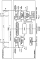
- the electronic system for operating the NDIR sub-assembly in one embodiment is schematically illustrated in FIG. 7 .
- the electronic system includes electronic devices selected to provide power to the IR source, the IR source heater, the IR detector, the IR detector heater, and other electrical components.
- the electronics control system modulates the power to the IR source at a frequency of 55 Hz. Signals may be generated at other frequencies for operation of other components, such as the bandpass filter and analog-to-digital converter, from a field-programmable gate array (FPGA) as is known in the art.
- FPGA field-programmable gate array
- the FPGA can be adapted or adjusted to generate a 55 Hz clock for the IR source, with a duty cycle suitable for its operation.
- the IR source driver converts the logic-level clock signal into the pulsed power required by the IR source.
- the IR source emits infrared light, modulated at 55 Hz. This light reaches the IR detector, attenuated by any CO 2 present in the center section 39 of the NDIR.
- the IR detector converts the infrared light that it receives back into an electrical signal, with signal content at 55Hz that is proportional to the infrared light that it receives.
- the detector bandpass filter is selected or adapted to remove harmonics of the 55 Hz signal and DC offset, lowfrequency noise, and high-frequency noise generated by the IR detector.
- a synchronous circuit such as a Switched-capacitor filter, is used in the detector bandpass filter, with a clock provided by the FPGA at a multiple of 55 HZ.
- the analog-to-digital converter samples the waveform from the detector bandpass filter, also using a clock provided by the FPGA at a whole number multiple of 55 Hz. For example, a clock of 5500 HZ provides 100 waveform samples per cycle of the IR detector waveform.
- the FPGA and the microprocessor perform further bandpass filtering of the digitized IR detector signal, centered at the modulation frequency of 55 Hz, to remove detector noise and noise from the AC mains at 50 Hz or 60 Hz. The amplitude of the 55 Hz signal at the output of the digital bandpass filter is then measured.
- the response of the IR detector is adjusted for temperature, pressure, and flow rate as necessary, and the CO 2 concentration is calculated in the manner described above. Based on the description provided herein, the processing steps described above could readily be implemented by one of ordinary skill in this art using an apparatus in accordance with the described embodiments.
- FIG. 8 illustrates a typical response curve of an NDIR during a carbon measurement sequence.
- the output is in instrument counts, and the counts are proportional to the amount of IR radiation that strikes the IR detector 60.
- the response is at its maximum or baseline level.
- the response decreases until it reaches a minimum (trough) that 32 corresponds to when the amount of CO 2 in section 39 has reached its maximum (maximum absorbance).
- the response returns to its original baseline level.
- the response peak can be used to calculate carbon concentrations in an aqueous sample being tested.
- the response curve can be mathematically integrated, and the resulting cone-shaped area of the response curve can be related to carbon concentration by one type of mathematical calibration correlation.
- the height of the peak can be measured and related to carbon concentration by another type of mathematical calibration correlation.
- These mathematical calibration correlations can be developed for a particular instrument by performing tests on samples containing known concentrations of IC, OC and/or TC. Basing computations on the measurement of peak height has the advantage that it is relatively unaffected by changes in gas flow rate.
- the reactor 26 is heated by the use of electrical current 902, passed directly through all or a portion of the reactor 26. Direct heating by electrical current may be used either in place of, or in addition to a heater 34 (as shown in FIG. 2 ).
- a power source 904 is used to pass the electrical current 902 through all or a portion of the reactor 206.
- the reactor material has a resistance R, that is inherent to the reactor material.
- P the power dissipated
- I the current flow through the material
- R the resistance of the material the electrical current flows through.
- sensing techniques as previously described may be applied. These include, but are not limited to, directly sensing the temperature of the reactor 26 using a temperature sensor 35 such as, for example, a RTD, detecting electromagnetic emissions produced by the reactor 26, and using an infrared (IR) sensor to measure the temperature of the reactor 26, and the like. Sensor 35 measurements produced may be used by a control circuit 908 to apply electrical current to the reactor 26, determine the magnitude or the applied current, and/or determine when to stop the flow of electrical current through the reactor 26. The control circuit 908 can use various inputs 910 to make these determinations in addition to sensed temperature of the reactor 26, including positions of valves, status of the measurement apparatus, and the like.
- a temperature sensor 35 such as, for example, a RTD
- IR infrared
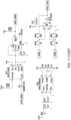
- FIG. 10 illustrates a schematic diagram of either all or part of an exemplary circuit 908 for heating and controlling the reactor 26.
- FIG. 10 includes instrumentation amplifiers and DC converters configured to implement a reactor heating system.
- FIG. 11 also illustrates a schematic diagram of either all or part of an exemplary circuit 908 for heating and controlling the reactor 26.
- FIG. 11 includes amplifiers, and an optoisolator, configured to implement a reactor heating system.
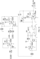
- FIG. 12 also illustrates a schematic diagram of either all or part of an exemplary circuit 908 for heating and controlling the reactor 26.
- FIG. 12 includes a configuration of comparators used to implement an exemplary reactor heating circuit.
- FIG. 13 illustrates a schematic diagram of either all or part of an exemplary circuit 908 for heating and controlling the reactor.
- FIG. 13 includes a configuration of amplifiers used to implement an exemplary reactor heating circuit.
- the schematics disclosed in FIG. 10 , FIG. 11 , FIG. 12 , and FIG. 13 are intended to be non-limiting examples, which may be applied separately or in various combinations.
Landscapes
- Chemical & Material Sciences (AREA)
- Health & Medical Sciences (AREA)
- Physics & Mathematics (AREA)
- Life Sciences & Earth Sciences (AREA)
- Analytical Chemistry (AREA)
- General Health & Medical Sciences (AREA)
- General Physics & Mathematics (AREA)
- Immunology (AREA)
- Pathology (AREA)
- Biochemistry (AREA)
- Engineering & Computer Science (AREA)
- Spectroscopy & Molecular Physics (AREA)
- Food Science & Technology (AREA)
- Medicinal Chemistry (AREA)
- Dispersion Chemistry (AREA)
- Hematology (AREA)
- Clinical Laboratory Science (AREA)
- Chemical Kinetics & Catalysis (AREA)
- Combustion & Propulsion (AREA)
- Automation & Control Theory (AREA)
- Investigating Or Analyzing Non-Biological Materials By The Use Of Chemical Means (AREA)
Claims (14)
- Vorrichtung zum Behandeln einer flüssigen Probe, die organisches Material enthält, wobei die Vorrichtung umfasst:einen Reaktor (26) mit Reaktoreinlass- und Reaktorauslassöffnungen und einem Reaktorinneren zum Halten einer Flüssigkeitsprobe bei Bedingungen über Umgebungstemperatur und -druck;Hochdruckfluidreaktorventilelemente (28, 29) an den Reaktoreinlass- und Reaktorauslassöffnungen, wobei die Reaktorventilelemente (28, 29) im offenen Ventilmodus einen Fuidfluss in das bzw. aus dem Reaktorinneren ermöglichen oder alternativ im geschlossenen Ventilmodus in der Lage sind, das Reaktorinnere abzudichten;ein Reaktorheizsystem, das eine elektrische Stromquelle umfasst, die betriebsmäßig mit dem Reaktor (26) verbunden ist, wobei die elektrische Stromquelle konfiguriert ist zum Leiten eines elektrischen Stroms (902) durch den Reaktor (26), zum Erhitzen des Reaktorinneren und einer in dem Reaktorinneren abgedichteten Fluidprobe schnell und zyklisch auf eine Temperatur von etwa 150 °C bis 650 °C oder mehr, während das Reaktorinnere und die Reaktorventilelemente (28, 29) die Probe unter abgedichteten Bedingungen halten; undein Reaktorkühlsystem, das zum schnellen und zyklischen Abkühlen des Reaktorinneren und eines im Reaktorinneren abgedichteten Reaktorprodukts nach einem Heizzyklus angepasst ist.
- Vorrichtung nach Anspruch 1, wobei ein Sensor (35) konfiguriert ist zum Bestimmen eines Temperaturwerts des Reaktors (26).
- Vorrichtung nach Anspruch 2, wobei der Sensor (35) konfiguriert ist zum Messen elektromagnetischer Strahlung.
- Vorrichtung nach einem der Ansprüche 2 oder 3, wobei der Sensor (35) konfiguriert ist zum Messen von Infrarotstrahlung.
- Vorrichtung nach einem der Ansprüche 2, 3 oder 4, wobei der Sensor (35) betriebsmäßig mit dem Reaktorheizsystem verbunden ist.
- Vorrichtung nach einem der Ansprüche 2, 3, 4 oder 5, wobei der Sensor (35) betriebsmäßig mit dem Reaktorkühlsystem verbunden ist.
- Vorrichtung nach einem der Ansprüche 2, 3, 4, 5 oder 6, wobei der Reaktor (26) aus Titan und seinen Legierungen, Tantal, Inconel 625, Hastelloy C-276 oder Kombinationen davon aufgebaut ist.
- Verfahren zum Behandeln einer Flüssigkeitsprobe, die organisches Material enthält, unter Verwendung einer Vorrichtung zum Behandeln von Flüssigkeitsproben, wobei das Verfahren die Schritte umfasst:
Bereitstellen einer Vorrichtung zur Behandlung von Flüssigkeitsproben, die die folgenden Merkmale umfasst:einen Reaktor (26) mit Reaktoreinlass- und Reaktorauslassöffnungen und einem Reaktorinneren zur Aufnahme einer Flüssigkeitsprobe bei Bedingungen über Umgebungstemperatur und -druck;Hochdruckfluidreaktorventilelemente (28, 29) an den Reaktoreinlass- und Reaktorauslassöffnungen, wobei die Reaktorventilelemente (28, 29) im offenen Ventilmodus einen Fuidfluss in das bzw. aus dem Reaktorinneren ermöglichen oder alternativ im geschlossenen Ventilmodus das Reaktorinnere abdichten können;ein Reaktorheizsystem, das eine elektrische Stromquelle umfasst, die betriebsmäßig mit dem Reaktor (26) verbunden ist, wobei die elektrische Stromquelle konfiguriert ist zum Leiten eines elektrischen Stroms (902) durch den Reaktor (26), zum Erhizten des Reaktorinneren und einer in dem Reaktorinneren abgedichteten Fluidprobe schnell und zyklisch auf eine Temperatur von etwa 150 °C bis 650 °C oder mehr, während das Reaktorinnere und die Reaktorventilelemente (28, 29) die Probe unter abgedichteten Bedingungen halten;
undein Reaktorkühlsystem, das zum schnellen und zyklischen Abkühlen des Reaktorinneren und eines im Reaktorinneren abgedichteten Reaktorprodukts nach einem Heizzyklus angepasst ist;Mischen eines bekannten Volumens der Probe mit einer oder mehreren anderen Flüssigkeiten, ausgewählt aus Oxidationsmittel, Säure und Verdünnungswasser, um eine Probenmischung zu bilden;Einströmen von mindestens einem Teil des Probengemischs in das Innere des Reaktors (26), wobei der Reaktor (26) so angepasst ist, dass er an den Reaktoreinlass- und Reaktorauslassöffnungen abwechselnd und wiederholt geöffnet und verschlossen werden kann;Abdichten des Teils des Probengemischs in dem Inneren des Reaktors durch Schließen der Ventilelemente (28, 29) an den Reaktoreinlass- und Reaktorauslassöffnungen;Leiten eines elektrischen Stroms (902) durch den Reaktor (26) für eine Zeit, die ausreichend ist, um das organische Material im Wesentlichen zu oxidieren und das Reaktorprodukt zu bilden;Beenden des Heizschritts und anschließendes schnelles Abkühlen des Inneren des Reaktors (26) und des Reaktorprodukts innerhalb auf im Wesentlichen Umgebungsbedingungen, um gekühlte flüssige und gasförmige Reaktorprodukte zu bilden; undÖffnen des Reaktors (26) und Entfernen der gekühlten flüssigen und gasförmigen Reaktorprodukte aus dem Reaktorinneren. - Verfahren nach Anspruch 8, wobei das Innere des Reaktors (26) und der darin befindliche Probenabschnitt schnell auf eine Temperatur zwischen 150 °C und etwa 650 °C erhitzt werden.
- Verfahren nach einem der Ansprüche 8 oder 9, wobei ein Sensor (35) bereitgestellt wird, wobei der Sensor konfiguriert ist, einen Temperaturwert des Reaktors (26) zu messen.
- Verfahren nach Anspruch 10, wobei der Sensor (35) zum Messen elektromagnetischer Strahlung konfiguriert ist.
- Verfahren nach einem der Ansprüche 10 oder 11, wobei der Sensor (35) konfiguriert ist zum Messen von Infrarotstrahlung.
- Verfahren nach einem der Ansprüche 8, 9, 10, 11 oder 12, wobei ein von dem Sensor (35) erzeugtes Signal verwendet wird, um zu entscheiden, wann der Heizschritt beendet werden soll.
- Verfahren nach einem der Ansprüche 8, 9, 10, 11, 12 und 13, wobei der Reaktor (26) aus Titan und seinen Legierungen, Tantal, Inconel 625, Hastelloy C-276 oder Kombinationen davon aufgebaut ist.
Applications Claiming Priority (1)
| Application Number | Priority Date | Filing Date | Title |
|---|---|---|---|
| PCT/US2019/065626 WO2021118550A1 (en) | 2019-12-11 | 2019-12-11 | Carbon measurements in aqueous samples using oxidation at elevated temperatures and pressures created by resistive heating |
Publications (2)
| Publication Number | Publication Date |
|---|---|
| EP4073507A1 EP4073507A1 (de) | 2022-10-19 |
| EP4073507B1 true EP4073507B1 (de) | 2025-02-05 |
Family
ID=69173396
Family Applications (1)
| Application Number | Title | Priority Date | Filing Date |
|---|---|---|---|
| EP19838993.4A Active EP4073507B1 (de) | 2019-12-11 | 2019-12-11 | Kohlenstoffmessungen in wässrigen proben mittels oxidation bei erhöhten temperaturen und drücken durch widerstandserwärmung |
Country Status (6)
| Country | Link |
|---|---|
| US (1) | US12578267B2 (de) |
| EP (1) | EP4073507B1 (de) |
| JP (1) | JP7498776B2 (de) |
| CN (1) | CN115427805A (de) |
| CA (1) | CA3161658A1 (de) |
| WO (1) | WO2021118550A1 (de) |
Family Cites Families (7)
| Publication number | Priority date | Publication date | Assignee | Title |
|---|---|---|---|---|
| DE19727839A1 (de) * | 1997-06-24 | 1999-01-28 | Lar Analytik Und Umweltmestech | Verfahren zur Bestimmung eines Wasserinhaltsstoffes |
| WO2000042293A1 (fr) * | 1999-01-12 | 2000-07-20 | Sheiichi Akiba | Systeme generateur automatique a chauffage par resistance |
| DE19955150B4 (de) * | 1999-11-17 | 2010-08-05 | Karlsruher Institut für Technologie | Verfahren zur Erzeugung von Wasserstoff |
| US20080038163A1 (en) | 2006-06-23 | 2008-02-14 | Applera Corporation | Systems and Methods for Cooling in Biological Analysis Instruments |
| US20080198381A1 (en) * | 2007-02-21 | 2008-08-21 | Teledyne Tekmar Company | Pressurized detectors substance analyzer |
| WO2009032205A2 (en) | 2007-09-05 | 2009-03-12 | Ge Analytical Instruments, Inc. | Carbon measurement in aqueous samples using oxidation at elevated temperatures and pressures |
| US11110450B2 (en) * | 2016-01-29 | 2021-09-07 | Hewlett-Packard Development Company, L.P. | Sample-reagent mixture thermal cycling |
-
2019
- 2019-12-11 EP EP19838993.4A patent/EP4073507B1/de active Active
- 2019-12-11 JP JP2022535925A patent/JP7498776B2/ja active Active
- 2019-12-11 WO PCT/US2019/065626 patent/WO2021118550A1/en not_active Ceased
- 2019-12-11 CN CN201980103550.7A patent/CN115427805A/zh active Pending
- 2019-12-11 US US17/784,602 patent/US12578267B2/en active Active
- 2019-12-11 CA CA3161658A patent/CA3161658A1/en active Pending
Also Published As
| Publication number | Publication date |
|---|---|
| US12578267B2 (en) | 2026-03-17 |
| WO2021118550A1 (en) | 2021-06-17 |
| JP7498776B2 (ja) | 2024-06-12 |
| EP4073507A1 (de) | 2022-10-19 |
| CA3161658A1 (en) | 2021-06-17 |
| CN115427805A (zh) | 2022-12-02 |
| US20230012945A1 (en) | 2023-01-19 |
| JP2023514006A (ja) | 2023-04-05 |
Similar Documents
| Publication | Publication Date | Title |
|---|---|---|
| US8101417B2 (en) | Carbon measurement in aqueous samples using oxidation at elevated temperatures and pressures | |
| US7556773B2 (en) | Analyzer device and method | |
| KR101723883B1 (ko) | 일체형 산화반응조를 구비한 총유기탄소 측정장치 및 측정방법 | |
| KR102414181B1 (ko) | 총유기탄소 측정장치 | |
| JP2009288228A (ja) | 自動分析定量観測方法および自動分析定量観測装置 | |
| CN105738287B (zh) | 水质分析仪 | |
| JPH08509549A (ja) | 流体媒体分析装置 | |
| KR102396696B1 (ko) | 초음파 진동을 이용한 toc 측정장치 및 toc 측정방법 | |
| CN111272524B (zh) | 稀释样品液体的方法和用于后续分析的稀释单元 | |
| EP4073507B1 (de) | Kohlenstoffmessungen in wässrigen proben mittels oxidation bei erhöhten temperaturen und drücken durch widerstandserwärmung | |
| KR101455246B1 (ko) | 수성 샘플의 인 함량 측정 방법 및 장치 | |
| JP2017223583A (ja) | 水質分析計 | |
| KR101809021B1 (ko) | 전도도법 검출방식의 총유기탄소 측정 센서 및 이를 이용한 총유기탄소 검출 시스템 | |
| JP3911820B2 (ja) | イオン濃度計測装置 | |
| JP3911821B2 (ja) | イオン濃度計測装置 | |
| JP2001124757A (ja) | 3態窒素分析システムにおけるシステムの自己診断方法 | |
| JPH1010050A (ja) | 三態窒素計の気化分離器 | |
| JPH11304711A (ja) | 水中の3態窒素分析における自動校正方法及び装置 | |
| JPS62185142A (ja) | 分析ガス捕集装置 |
Legal Events
| Date | Code | Title | Description |
|---|---|---|---|
| STAA | Information on the status of an ep patent application or granted ep patent |
Free format text: STATUS: UNKNOWN |
|
| STAA | Information on the status of an ep patent application or granted ep patent |
Free format text: STATUS: THE INTERNATIONAL PUBLICATION HAS BEEN MADE |
|
| PUAI | Public reference made under article 153(3) epc to a published international application that has entered the european phase |
Free format text: ORIGINAL CODE: 0009012 |
|
| STAA | Information on the status of an ep patent application or granted ep patent |
Free format text: STATUS: REQUEST FOR EXAMINATION WAS MADE |
|
| 17P | Request for examination filed |
Effective date: 20220704 |
|
| AK | Designated contracting states |
Kind code of ref document: A1 Designated state(s): AL AT BE BG CH CY CZ DE DK EE ES FI FR GB GR HR HU IE IS IT LI LT LU LV MC MK MT NL NO PL PT RO RS SE SI SK SM TR |
|
| DAV | Request for validation of the european patent (deleted) | ||
| DAX | Request for extension of the european patent (deleted) | ||
| P01 | Opt-out of the competence of the unified patent court (upc) registered |
Effective date: 20230521 |
|
| GRAP | Despatch of communication of intention to grant a patent |
Free format text: ORIGINAL CODE: EPIDOSNIGR1 |
|
| STAA | Information on the status of an ep patent application or granted ep patent |
Free format text: STATUS: GRANT OF PATENT IS INTENDED |
|
| INTG | Intention to grant announced |
Effective date: 20240730 |
|
| GRAS | Grant fee paid |
Free format text: ORIGINAL CODE: EPIDOSNIGR3 |
|
| GRAA | (expected) grant |
Free format text: ORIGINAL CODE: 0009210 |
|
| STAA | Information on the status of an ep patent application or granted ep patent |
Free format text: STATUS: THE PATENT HAS BEEN GRANTED |
|
| AK | Designated contracting states |
Kind code of ref document: B1 Designated state(s): AL AT BE BG CH CY CZ DE DK EE ES FI FR GB GR HR HU IE IS IT LI LT LU LV MC MK MT NL NO PL PT RO RS SE SI SK SM TR |
|
| REG | Reference to a national code |
Ref country code: GB Ref legal event code: FG4D |
|
| REG | Reference to a national code |
Ref country code: CH Ref legal event code: EP |
|
| REG | Reference to a national code |
Ref country code: IE Ref legal event code: FG4D |
|
| REG | Reference to a national code |
Ref country code: DE Ref legal event code: R096 Ref document number: 602019065642 Country of ref document: DE |
|
| REG | Reference to a national code |
Ref country code: NL Ref legal event code: MP Effective date: 20250205 |
|
| PG25 | Lapsed in a contracting state [announced via postgrant information from national office to epo] |
Ref country code: RS Free format text: LAPSE BECAUSE OF FAILURE TO SUBMIT A TRANSLATION OF THE DESCRIPTION OR TO PAY THE FEE WITHIN THE PRESCRIBED TIME-LIMIT Effective date: 20250505 |
|
| PG25 | Lapsed in a contracting state [announced via postgrant information from national office to epo] |
Ref country code: FI Free format text: LAPSE BECAUSE OF FAILURE TO SUBMIT A TRANSLATION OF THE DESCRIPTION OR TO PAY THE FEE WITHIN THE PRESCRIBED TIME-LIMIT Effective date: 20250205 |
|
| PG25 | Lapsed in a contracting state [announced via postgrant information from national office to epo] |
Ref country code: PL Free format text: LAPSE BECAUSE OF FAILURE TO SUBMIT A TRANSLATION OF THE DESCRIPTION OR TO PAY THE FEE WITHIN THE PRESCRIBED TIME-LIMIT Effective date: 20250205 |
|
| PG25 | Lapsed in a contracting state [announced via postgrant information from national office to epo] |
Ref country code: ES Free format text: LAPSE BECAUSE OF FAILURE TO SUBMIT A TRANSLATION OF THE DESCRIPTION OR TO PAY THE FEE WITHIN THE PRESCRIBED TIME-LIMIT Effective date: 20250205 |
|
| REG | Reference to a national code |
Ref country code: LT Ref legal event code: MG9D |
|
| PG25 | Lapsed in a contracting state [announced via postgrant information from national office to epo] |
Ref country code: NO Free format text: LAPSE BECAUSE OF FAILURE TO SUBMIT A TRANSLATION OF THE DESCRIPTION OR TO PAY THE FEE WITHIN THE PRESCRIBED TIME-LIMIT Effective date: 20250505 Ref country code: IS Free format text: LAPSE BECAUSE OF FAILURE TO SUBMIT A TRANSLATION OF THE DESCRIPTION OR TO PAY THE FEE WITHIN THE PRESCRIBED TIME-LIMIT Effective date: 20250605 |
|
| PG25 | Lapsed in a contracting state [announced via postgrant information from national office to epo] |
Ref country code: NL Free format text: LAPSE BECAUSE OF FAILURE TO SUBMIT A TRANSLATION OF THE DESCRIPTION OR TO PAY THE FEE WITHIN THE PRESCRIBED TIME-LIMIT Effective date: 20250205 |
|
| PG25 | Lapsed in a contracting state [announced via postgrant information from national office to epo] |
Ref country code: HR Free format text: LAPSE BECAUSE OF FAILURE TO SUBMIT A TRANSLATION OF THE DESCRIPTION OR TO PAY THE FEE WITHIN THE PRESCRIBED TIME-LIMIT Effective date: 20250205 |
|
| PG25 | Lapsed in a contracting state [announced via postgrant information from national office to epo] |
Ref country code: LV Free format text: LAPSE BECAUSE OF FAILURE TO SUBMIT A TRANSLATION OF THE DESCRIPTION OR TO PAY THE FEE WITHIN THE PRESCRIBED TIME-LIMIT Effective date: 20250205 Ref country code: PT Free format text: LAPSE BECAUSE OF FAILURE TO SUBMIT A TRANSLATION OF THE DESCRIPTION OR TO PAY THE FEE WITHIN THE PRESCRIBED TIME-LIMIT Effective date: 20250605 |
|
| PG25 | Lapsed in a contracting state [announced via postgrant information from national office to epo] |
Ref country code: BG Free format text: LAPSE BECAUSE OF FAILURE TO SUBMIT A TRANSLATION OF THE DESCRIPTION OR TO PAY THE FEE WITHIN THE PRESCRIBED TIME-LIMIT Effective date: 20250205 Ref country code: GR Free format text: LAPSE BECAUSE OF FAILURE TO SUBMIT A TRANSLATION OF THE DESCRIPTION OR TO PAY THE FEE WITHIN THE PRESCRIBED TIME-LIMIT Effective date: 20250506 |
|
| REG | Reference to a national code |
Ref country code: AT Ref legal event code: MK05 Ref document number: 1764972 Country of ref document: AT Kind code of ref document: T Effective date: 20250205 |
|
| PG25 | Lapsed in a contracting state [announced via postgrant information from national office to epo] |
Ref country code: SE Free format text: LAPSE BECAUSE OF FAILURE TO SUBMIT A TRANSLATION OF THE DESCRIPTION OR TO PAY THE FEE WITHIN THE PRESCRIBED TIME-LIMIT Effective date: 20250205 |
|
| PG25 | Lapsed in a contracting state [announced via postgrant information from national office to epo] |
Ref country code: SM Free format text: LAPSE BECAUSE OF FAILURE TO SUBMIT A TRANSLATION OF THE DESCRIPTION OR TO PAY THE FEE WITHIN THE PRESCRIBED TIME-LIMIT Effective date: 20250205 |
|
| PG25 | Lapsed in a contracting state [announced via postgrant information from national office to epo] |
Ref country code: DK Free format text: LAPSE BECAUSE OF FAILURE TO SUBMIT A TRANSLATION OF THE DESCRIPTION OR TO PAY THE FEE WITHIN THE PRESCRIBED TIME-LIMIT Effective date: 20250205 |
|
| PG25 | Lapsed in a contracting state [announced via postgrant information from national office to epo] |
Ref country code: IT Free format text: LAPSE BECAUSE OF FAILURE TO SUBMIT A TRANSLATION OF THE DESCRIPTION OR TO PAY THE FEE WITHIN THE PRESCRIBED TIME-LIMIT Effective date: 20250205 |
|
| PG25 | Lapsed in a contracting state [announced via postgrant information from national office to epo] |
Ref country code: AT Free format text: LAPSE BECAUSE OF FAILURE TO SUBMIT A TRANSLATION OF THE DESCRIPTION OR TO PAY THE FEE WITHIN THE PRESCRIBED TIME-LIMIT Effective date: 20250205 |
|
| PG25 | Lapsed in a contracting state [announced via postgrant information from national office to epo] |
Ref country code: EE Free format text: LAPSE BECAUSE OF FAILURE TO SUBMIT A TRANSLATION OF THE DESCRIPTION OR TO PAY THE FEE WITHIN THE PRESCRIBED TIME-LIMIT Effective date: 20250205 Ref country code: CZ Free format text: LAPSE BECAUSE OF FAILURE TO SUBMIT A TRANSLATION OF THE DESCRIPTION OR TO PAY THE FEE WITHIN THE PRESCRIBED TIME-LIMIT Effective date: 20250205 |
|
| PG25 | Lapsed in a contracting state [announced via postgrant information from national office to epo] |
Ref country code: RO Free format text: LAPSE BECAUSE OF FAILURE TO SUBMIT A TRANSLATION OF THE DESCRIPTION OR TO PAY THE FEE WITHIN THE PRESCRIBED TIME-LIMIT Effective date: 20250205 |
|
| PG25 | Lapsed in a contracting state [announced via postgrant information from national office to epo] |
Ref country code: SK Free format text: LAPSE BECAUSE OF FAILURE TO SUBMIT A TRANSLATION OF THE DESCRIPTION OR TO PAY THE FEE WITHIN THE PRESCRIBED TIME-LIMIT Effective date: 20250205 |
|
| REG | Reference to a national code |
Ref country code: DE Ref legal event code: R097 Ref document number: 602019065642 Country of ref document: DE |
|
| PLBE | No opposition filed within time limit |
Free format text: ORIGINAL CODE: 0009261 |
|
| STAA | Information on the status of an ep patent application or granted ep patent |
Free format text: STATUS: NO OPPOSITION FILED WITHIN TIME LIMIT |
|
| PGFP | Annual fee paid to national office [announced via postgrant information from national office to epo] |
Ref country code: GB Payment date: 20251229 Year of fee payment: 7 |
|
| 26N | No opposition filed |
Effective date: 20251106 |
|
| PGFP | Annual fee paid to national office [announced via postgrant information from national office to epo] |
Ref country code: FR Payment date: 20251226 Year of fee payment: 7 |
|
| PGFP | Annual fee paid to national office [announced via postgrant information from national office to epo] |
Ref country code: DE Payment date: 20251229 Year of fee payment: 7 |