EP4072925B1 - Elektrisch angetriebenes kraftfahrzeug mit verstärkter wippe - Google Patents
Elektrisch angetriebenes kraftfahrzeug mit verstärkter wippe Download PDFInfo
- Publication number
- EP4072925B1 EP4072925B1 EP20816554.8A EP20816554A EP4072925B1 EP 4072925 B1 EP4072925 B1 EP 4072925B1 EP 20816554 A EP20816554 A EP 20816554A EP 4072925 B1 EP4072925 B1 EP 4072925B1
- Authority
- EP
- European Patent Office
- Prior art keywords
- reinforcement
- motor vehicle
- longitudinal
- vehicle
- section
- Prior art date
- Legal status (The legal status is an assumption and is not a legal conclusion. Google has not performed a legal analysis and makes no representation as to the accuracy of the status listed.)
- Active
Links
- 230000002787 reinforcement Effects 0.000 claims description 133
- 230000006835 compression Effects 0.000 claims description 14
- 238000007906 compression Methods 0.000 claims description 14
- 238000003466 welding Methods 0.000 claims description 3
- 230000035939 shock Effects 0.000 description 5
- 238000010276 construction Methods 0.000 description 2
- 238000000034 method Methods 0.000 description 2
- 229910000831 Steel Inorganic materials 0.000 description 1
- 238000010521 absorption reaction Methods 0.000 description 1
- 238000002485 combustion reaction Methods 0.000 description 1
- 239000002828 fuel tank Substances 0.000 description 1
- 238000004519 manufacturing process Methods 0.000 description 1
- 239000000463 material Substances 0.000 description 1
- 230000035515 penetration Effects 0.000 description 1
- 230000003014 reinforcing effect Effects 0.000 description 1
- 239000010959 steel Substances 0.000 description 1
Images


Classifications
-
- B—PERFORMING OPERATIONS; TRANSPORTING
- B62—LAND VEHICLES FOR TRAVELLING OTHERWISE THAN ON RAILS
- B62D—MOTOR VEHICLES; TRAILERS
- B62D25/00—Superstructure or monocoque structure sub-units; Parts or details thereof not otherwise provided for
- B62D25/02—Side panels
- B62D25/025—Side sills thereof
-
- B—PERFORMING OPERATIONS; TRANSPORTING
- B62—LAND VEHICLES FOR TRAVELLING OTHERWISE THAN ON RAILS
- B62D—MOTOR VEHICLES; TRAILERS
- B62D21/00—Understructures, i.e. chassis frame on which a vehicle body may be mounted
- B62D21/15—Understructures, i.e. chassis frame on which a vehicle body may be mounted having impact absorbing means, e.g. a frame designed to permanently or temporarily change shape or dimension upon impact with another body
- B62D21/157—Understructures, i.e. chassis frame on which a vehicle body may be mounted having impact absorbing means, e.g. a frame designed to permanently or temporarily change shape or dimension upon impact with another body for side impacts
-
- B—PERFORMING OPERATIONS; TRANSPORTING
- B62—LAND VEHICLES FOR TRAVELLING OTHERWISE THAN ON RAILS
- B62D—MOTOR VEHICLES; TRAILERS
- B62D25/00—Superstructure or monocoque structure sub-units; Parts or details thereof not otherwise provided for
- B62D25/20—Floors or bottom sub-units
Definitions
- the invention relates to the field of motor vehicles, and more particularly to the structure of a motor vehicle with electric traction (hybrid or pure electric).
- a motor vehicle with electric traction generally comprises, for its operation, an electric motor and possibly a combustion engine coupled to said electric motor. Traction batteries are also provided in these vehicles to power the electric motor.
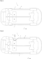
- FIG 1 shows a bottom view of a motor vehicle 1 with electric traction, as previously described.
- the vehicle 1 comprises a body structure 3 with a floor 5 and two lower body beams 7 which extend longitudinally on either side and laterally of said floor 5.
- the vehicle 1 further comprises rear wheels 9 attached to a rear axle 11, and batteries 13 positioned under the floor 5 in front of the wheels 9 and the rear axle 11.
- An x axis represents, on the figures 1 and 2 , the direction of movement of vehicle 1.
- the published patent document FR 3 011 801 B1 discloses a motor vehicle structure where the lower body beams have a particular profile and each contain a longitudinal reinforcement.
- This construction of the underbody beams is designed to be lighter by using steel sheets with an ultra high limit of elasticity (UHLE). This construction is therefore not suitable for reinforcement for a heavier structure due to the presence of traction batteries. Also, it is not suitable for protecting in particular the rear area where the fuel tank is housed.
- UHLE ultra high limit of elasticity
- the document JP 2006 218987 A describes a motor vehicle according to the preamble of claim 1.
- the invention aims to overcome at least one of the disadvantages of the aforementioned state of the art. More particularly, the invention aims to reduce the damage caused to the structure of a vehicle during a lateral pole impact, in particular at the level of a rear part of the lower body beams and for traction vehicles. electric housing traction batteries in a rear part of the floor.
- the subject of the invention is a motor vehicle with a body structure comprising a floor with a rear portion forming a projection, and two beams extending longitudinally on either side laterally of said floor, at least one of said beams comprising: a interior spar and an exterior spar assembled together and delimiting an interior volume; and a longitudinal reinforcement arranged in the interior volume; remarkable in that the longitudinal reinforcement extends rearward beyond the projection; and the at least one beam further comprises: a compression reinforcement, called internal reinforcement, positioned longitudinally at the level of the projection, and arranged in a hollow section of the internal spar so as to serve as support for the longitudinal reinforcement in the event of lateral impact against a rear end of the beam.
- a compression reinforcement called internal reinforcement
- the vehicle further comprises a rear profile extending from each of the rear ends of the two beams, towards the rear and inclined towards the interior of the vehicle, and for each of the other less a beam, the vehicle includes a compression reinforcement, called rear profile reinforcement, positioned longitudinally at the level of the interior reinforcement, and arranged in the corresponding rear profile.
- the longitudinal reinforcement has a lying U-shaped cross section and is positioned in a hollow of the outer spar, the at least one beam comprising a rear reinforcement disposed in the outer spar and having a surface of support receiving a rear end of said longitudinal reinforcement.
- the cross section of the longitudinal reinforcement has at each end a wing arranged in an upper and lower junction rebate, respectively, of the inner and outer longitudinal members.
- the at least one beam comprises a compression reinforcement, called external reinforcement, arranged in the lying U-shaped cross section of the longitudinal reinforcement and positioned longitudinally at the level of the internal reinforcement.
- the exterior spar has a lying U-shaped section with a vertical core and two horizontal flanges, the cross section of the longitudinal reinforcement having at each end of the lying U a wing fixed against an interior face of said core .
- the longitudinal reinforcement has a cross section with a closed contour and the at least one beam comprises a rear reinforcement disposed in the exterior spar and having a recess receiving a rear end of said longitudinal reinforcement.
- each of the interior reinforcement(s), where appropriate exterior(s) and, where appropriate, rear profile is a stamped shape with first wall portions extending longitudinally and of the second wall portions extending transversely, so as to provide a compression reinforcement function in the event of a lateral impact.
- each of the interior reinforcement(s) and, where applicable, of the rear profile has an undulated horizontal profile forming, along said undulation, alternately the longitudinal wall portions and transverse.
- each of the external reinforcement(s) has a horizontal U-shaped profile with a core forming the longitudinal portion and two wings forming the transverse portions, each of said wings having legs fixed by welding to the corresponding longitudinal reinforcement.
- the measures of the invention are interesting in that they make it possible to limit the deformations caused during a lateral pole impact, in particular during a lateral pole impact caused at the level of the batteries of an electric traction vehicle. Thus, reducing the depth makes it possible to improve the safety of passengers in the vehicle, by avoiding the introduction of foreign elements into the battery tray.
- the invention is also easily adaptable, depending on the range of vehicles that one wishes to equip. Finally, this invention is easy to implement and manufacture, thanks to materials and techniques known to those skilled in the art.
- the examples described below are given for information only, but other applications or embodiments of the invention not described can be considered.
- the x axis represents, in all of these figures, the direction of movement of the vehicle.
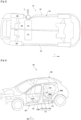
- THE figures 3 and 4 show, respectively, a view from below of a motor vehicle according to the invention following a side pole impact, and a perspective view of a body structure of said vehicle according to the invention. These figures repeat the numbering of the previous figures for identical or similar elements, the numbering however being incremented by 100. Reference is also made to the description of these elements in relation to the prior art.
- FIG. 3 shows in particular a view of the underside of the vehicle, during a side pole impact similar to that shown in figure 2 , in the case where the vehicle includes reinforcements according to the invention.
- the vehicle 101 comprises the body structure 103 with a floor 105 and two beams 107 which extend longitudinally on either side and laterally said floor 105.
- the vehicle 101 further comprises rear wheels 109 attached to a rear axle 111, as well as traction batteries 113 of the vehicle 101 positioned under the floor 105 at the front of said wheels 109 and the rear axle 111 During a lateral post impact (represented by an arrow C), the beam 107, positioned on the left side of the vehicle 101, sinks to the level of the battery 113.
- reinforcements according to the invention (described more precisely in figs 5 to 10), on the other hand limit the depression of the body structure 103, and make it possible to avoid the introduction of foreign elements into the traction batteries 113. These reinforcements will be more particularly described in figures 5 to 10 .
- each beam 107 comprises an interior spar 115 and an exterior spar 117 assembled together and delimiting a volume interior. More precisely, the outer spar 117 has a lying U-shaped cross section, comprising a vertical core 117A and two upper 117B and lower 117C horizontal flanges.
- These soles comprise at their ends wings forming, with the wings of the corresponding soles of the inner spar 115 (the soles of the inner spar not being visible on the figures 3 and 4 ), an upper junction rabbet 119A and a lower junction rabbet 119B.
- the exterior spar 117 will no longer be shown in the following figures.
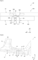
- THE figures 5, 6 And 7 show different views of the beam comprising reinforcements according to a first embodiment of the invention.
- the beam shown in these figures is a beam adapted to be mounted on a right side of a vehicle.
- the interior spar 115 of the beam 107 presents, like the exterior spar described in Figure 4 , a lying U-shaped cross section comprising a vertical core 115A and the two horizontal flanges upper 115B and lower 115C.
- a longitudinal reinforcement 121 which extends towards the rear beyond the projection (visible at the figure 4 ).
- the beam 107 further comprises an interior reinforcement 123, which is a compression reinforcement.
- This reinforcement 123 is positioned longitudinally at the level of the projection, and is positioned in a hollow section of the internal spar 115.
- This reinforcement 123 serves to support the longitudinal reinforcement 121 during a lateral impact against a rear end 107A of the beam 107.
- the interior reinforcement 123 is advantageously a stamped shape, with first wall portions 123A extending longitudinally and second wall portions 123B extending transversely, thus forming a corrugated horizontal profile providing a compression reinforcement function during an impact. lateral.
- the interior reinforcement 123 alternately comprises the longitudinal wall portions 123A and transverse 123B.
- the vehicle further comprises a rear profile 125 commonly called a spar, which extends from the rear end 107A of the beam 107 towards the rear and inclined towards the interior of the vehicle.
- this rear profile 125 extends between the beam 107 and the batteries (visible at figures 1 to 3 ).
- the rear profile 125 has a triangular shape with an interior wall 125A which extends from an upper face 125B of said profile 125 and towards the top of the vehicle.
- This rear profile 125 supports a rear profile reinforcement 127, which is a compression reinforcement, and which is positioned longitudinally at the level of the interior reinforcement 123.
- the rear profile reinforcement 127 positioned between the interior wall 125A of the rear profile 125 and an interior face 115D of the interior spar 115, will absorb the shock thanks to the wavy horizontal profile shape of its stamping.
- this profile presents, alternatively, first portions of longitudinal walls 127A and second portions of transverse walls 127B which provide the function of reinforcement in compression during lateral impact.
- the invention further comprises a rear reinforcement 129 positioned in the external spar, and located at the level of the rear profile 125.
- the longitudinal reinforcement 121 has a lying U-shaped cross section, and is positioned in a hollow in the exterior spar (not visible to figures 5 to 7 ).
- the cross section of the longitudinal reinforcement 121 has a lying U shape with two wings 121A superimposed on two respective angles 121B arranged in the upper and lower junction rabbets, respectively, of the inner and outer longitudinal members 115.
- a rear end 121C of the longitudinal reinforcement 121 will be inserted into a bearing surface 129A of the rear reinforcement 129.
- the interior reinforcements 123 are three in number per beam 107, these reinforcements 123 being positioned successively and equidistant in the interior spar 115.
- the beam 107 further comprises a front reinforcement 131 positioned against an exterior face 115E of the interior spar 115, and at the front thereof.
- This front reinforcement 131 is positioned between the exterior face 115E of the interior spar 115 and the interior reinforcements 123 located at the front of the beam 107.
- This front reinforcement 131 coupled with the interior reinforcements 123, is intended to improve the resistance of the beam 107 in the event of a side impact caused at the front of the vehicle.
- the beam 107 further comprises an external reinforcement 133, said reinforcement 133 being a compression reinforcement.
- This exterior reinforcement 133 is positioned longitudinally in the cross section of the longitudinal reinforcement 121 and is positioned longitudinally at the level of the interior reinforcement 123.
- this exterior reinforcement 133 is a stamping with first wall portions 133A extending longitudinally and second portions of wall 133B extending transversely. This configuration of the external reinforcement 133 ensures the function of compression reinforcement during a lateral impact.
- the exterior reinforcements 133 are three in number per beam 107, each of said reinforcements 133 being positioned at the level of one of the interior reinforcements 123.
- each exterior reinforcement 133 has a horizontal U-shaped profile with a core 133A forming the longitudinal portion 133A and two wings 133B forming the transverse portions 133B.
- Each wing 133B further comprises tabs 133C fixed by welding to the corresponding longitudinal reinforcement 121.
- the beam 107 comprises a second row of external reinforcements 133', preferably three in number, the second row being positioned between the interior reinforcements 123 and the first row of exterior reinforcements 133 previously described, said second exterior reinforcements 133' having characteristics similar to the exterior reinforcements 133 of the first row.
- the second row of exterior reinforcements 133' is not shown in the Figure 7 .
- FIG 8 illustrates a second embodiment of the invention.
- This figure shows the numbering of the figures 3 to 7 previous for identical or similar elements, the number being however incremented by 100. Reference is also made to the description of these elements in relation to the first embodiment of the invention. More specifically, the figure 8 is a view of the left side of a vehicle.
- the longitudinal reinforcement 221 of the beam 207 has a cross section with a closed contour, more advantageously forming a hollow tube.
- This reinforcement 221 extends from the rear reinforcement 229 of the beam 207 towards the front of the vehicle 201, and more particularly, towards a middle pillar 203A of the body structure 203 of the vehicle 201.
- This rear reinforcement 229 also has , a recess 229A which receives a rear end 221A of the longitudinal reinforcement 221.
- the interior reinforcement 223 having the characteristics described in figures 5 to 7 previous ones.
- the rear profile 225 is also visible in this figure, and accommodates the rear profile reinforcement previously described (and not visible in this figure).
- the beam 207 further comprises two reinforcing profiles 235, these profiles 235 being positioned above and below the longitudinal reinforcement 221 and extend parallel to the latter, from the rear reinforcement 229 to the middle leg 203A .
- each of these profiles 235 forms an angle positioned between the upper and lower junction rabbets (described in figure 4 ) of the interior and exterior spars of beam 207.
- FIGS. 9 and 10 illustrate a third embodiment of the invention. These figures show the numbering of the figures 3 to 7 previous for identical or similar elements, the number being however incremented by 200. Reference is also made to the description of these elements in relation to the first and second embodiments of the invention. More specifically, these figures show two views of a beam reinforcement positioned on a left side of vehicle.
- the longitudinal reinforcement 321 of the beam 307 of the vehicle 301 extends from the rear reinforcement 329 towards the middle pillar 303A of the body structure 303 of vehicle 301.
- This longitudinal reinforcement 321 has a cross section in a lying U and is positioned in the hollow of the exterior spar (not visible on the figures 9 and 10 ) of the beam 307.
- Each upper and lower end of the reinforcement 321 has a wing 321A which will be fixed against the interior face of the web of the exterior spar.
- the rear reinforcement 329 has a bearing surface 329A capable of accommodating a rear end 321B of the longitudinal reinforcement 321.
- This embodiment also includes the rear profile reinforcement (not visible in this figure) and the interior reinforcement 323, which is a compression reinforcement, these reinforcements 323 allowing better absorption of lateral shocks. These two reinforcements 323 have the same characteristics as previously described in the first embodiment of the invention.
Landscapes
- Engineering & Computer Science (AREA)
- Chemical & Material Sciences (AREA)
- Combustion & Propulsion (AREA)
- Transportation (AREA)
- Mechanical Engineering (AREA)
- Body Structure For Vehicles (AREA)
- Arrangement Or Mounting Of Propulsion Units For Vehicles (AREA)
Claims (9)
- Kraftfahrzeug (101; 201 301) mit einer Karosseriestruktur (103; 203; 303) mit einem Boden (105) mit einem hinteren Teil (105A), der einen Vorsprung (105B) bildet, und zwei Trägern (107; 207; 307), die sich in Längsrichtung beiderseits des Bodens (105) erstrecken, mindestens eine der Balken (107; 207; 307. umfasst:- einen inneren Längsträger (115; 215; 315) und einem äußeren Längsträger (117), die miteinander verbunden sind und ein Innenvolumen begrenzen; und- eine Längsverstärkung (121; 221; 321) im Innenraum angeordnet ist;Längsverstärkung (121; 221; 321), die sich nach hinten über den Vorsprung (105B) hinaus erstreckt; und mindestens einem Träger (107; 207; 307), die ferner folgendes umfasst:- eine Verstärkung unter Druck, die so genannte innere Verstärkung (123; 223; 323) in Längsrichtung am Vorsprung (105B) positioniert und in einem hohlen Abschnitt des inneren Längsträgers (115; 215; 315) zur Unterstützung der Längsverstärkung (121; 221; 321) bei seitlichem Aufprall auf ein hinteres Ende (107A) des Trägers (107; 207; 307), dadurch gekennzeichnet, dass das Fahrzeug (101; 201 301) ferner ein Hinterprofil (125; 225; 325), die sich von jedem der hinteren Enden (107A) der beiden Träger (107; 207; 307) nach hinten und nach innen geneigt (101; 201 301) und für jeden der mindestens einen Balken (107; 207; 307) das Fahrzeug (101; 201 301) mit einer Pressverstärkung, der so genannten Hinterprofilverstärkung (127), die in Längsrichtung an der Innenverstärkung (123; 223; 323) und im hinteren Profil (125; 225; 325).
- Kraftfahrzeug (101; 301) nach Anspruch 1, dadurch gekennzeichnet, dass die Längsverstärkung (121; 321) einen U-förmigen Querschnitt aufweist und in einer Ausnehmung des äußeren Längsträgers (117) angeordnet ist, wobei der mindestens eine Träger (107; 307) mit einer hinteren Verstärkung (129; 329) im äußeren Längsträger (117) angeordnet und mit einer Auflagefläche (129A; 329A) zur Aufnahme eines hinteren Endes (121C; 321B) der Längsverstärkung (121; 321).
- Kraftfahrzeug (101) nach Anspruch 2, dadurch gekennzeichnet, dass der Querschnitt der Längsverstärkung (121) an jedem Ende einen Flügel (121A) aufweist, der in einer oberen und unteren Verbindungsfalte (119A, 119B) jeweils innere und äußere Längsträger (115, 111) angeordnet ist (17).
- Kraftfahrzeug (101) nach einem der Ansprüche 2 und 3, dadurch gekennzeichnet, dass der mindestens eine Träger (107) eine Druckverstärkung, die so genannte äußere Verstärkung (133), umfasst, die in dem beschichteten U-Querschnitt der Längsverstärkung (121) angeordnet und in Längsrichtung an der Innenverstärkung (123) positioniert ist.
- Kraftfahrzeug (301) nach Anspruch 2, dadurch gekennzeichnet, dass der äußere Längsträger einen U-förmigen Querschnitt aufweist, der mit einem vertikalen Kern und zwei horizontalen Sohlen liegend ist, wobei der Querschnitt der Längsverstärkung (321) an jedem Ende des U liegend einen Flügel (321A) aufweist, der an einer Innenseite des Kerns befestigt ist.
- Kraftfahrzeug (201) nach Anspruch 1, dadurch gekennzeichnet, dass die Längsverstärkung (221) einen Querschnitt mit geschlossener Kontur aufweist und der mindestens eine Träger (207) eine in dem Außenholm angeordnete hintere Verstärkung (229) mit einer Ausnehmung (229A) aufweist, die ein hinteres Ende (221A) der Längsverstärkung (221).
- Kraftfahrzeug (101; 201 301) nach einem der Ansprüche 4 bis 6, dadurch gekennzeichnet, dass jede der inneren Verstärkungen (123; 223; 323), gegebenenfalls außenseitig (133) und gegebenenfalls rückseitig (127), ist ein Mundstück mit ersten Wandteilen (123A, 127A, 133A; 223A; 323A) in Längsrichtung und zweite Wandteile (123B, 127B, 133B; 223B; 323B), die sich quer erstrecken, um bei einem seitlichen Aufprall eine Druckverstärkungsfunktion zu gewährleisten.
- Kraftfahrzeug (101; 201 301) nach Anspruch 7, dadurch gekennzeichnet, dass das Abziehen jeder der inneren Verstärkungen (123; 223; 323) und gegebenenfalls eines Hinterprofils (127) ein gewelltes Horizontalprofil aufweisen, das entlang dieser Wellung abwechselnd die Längswandteile (123A, 127A; 223A; 323A) und Quer (123B, 127B; 223B; 323B).
- Kraftfahrzeug (101) nach Anspruch 4 und nach einem der Ansprüche 7 und 8, dadurch gekennzeichnet, dass die Ausformung jeder der äußeren Verstärkungen (133) ein U-förmiges horizontales Profil mit einem den Längsabschnitt (133A) bildenden Kern (133A) und zwei Schenkeln (133B), die die Querabschnitte (133B) bilden, wobei jeder der Flügel (133B) Laschen (133C) aufweist, die durch Schweißen an der entsprechenden Längsverstärkung (121) befestigt sind.
Applications Claiming Priority (2)
| Application Number | Priority Date | Filing Date | Title |
|---|---|---|---|
| FR1914347A FR3104533B1 (fr) | 2019-12-13 | 2019-12-13 | Véhicule automobile à traction électrique avec bas de caisse renforcés |
| PCT/FR2020/052029 WO2021116546A1 (fr) | 2019-12-13 | 2020-11-06 | Véhicule automobile à traction électrique avec bas de caisse renforcés |
Publications (2)
| Publication Number | Publication Date |
|---|---|
| EP4072925A1 EP4072925A1 (de) | 2022-10-19 |
| EP4072925B1 true EP4072925B1 (de) | 2023-11-01 |
Family
ID=70008715
Family Applications (1)
| Application Number | Title | Priority Date | Filing Date |
|---|---|---|---|
| EP20816554.8A Active EP4072925B1 (de) | 2019-12-13 | 2020-11-06 | Elektrisch angetriebenes kraftfahrzeug mit verstärkter wippe |
Country Status (4)
| Country | Link |
|---|---|
| EP (1) | EP4072925B1 (de) |
| CN (1) | CN114829232A (de) |
| FR (1) | FR3104533B1 (de) |
| WO (1) | WO2021116546A1 (de) |
Family Cites Families (7)
| Publication number | Priority date | Publication date | Assignee | Title |
|---|---|---|---|---|
| JP3783546B2 (ja) * | 2000-10-11 | 2006-06-07 | 三菱自動車工業株式会社 | 車両のサイドシル構造 |
| JP4220971B2 (ja) * | 2005-02-10 | 2009-02-04 | 本田技研工業株式会社 | 自動車の後部車体構造 |
| JP5533587B2 (ja) * | 2010-11-19 | 2014-06-25 | マツダ株式会社 | 車両のサイドシル構造 |
| DE102011051622B4 (de) * | 2011-07-07 | 2021-03-25 | Dr. Ing. H.C. F. Porsche Aktiengesellschaft | Verstärkungselement für eine Fahrzeugstruktur, insbesondere für einen Schweller eines Kraftfahrzeugs |
| FR3011801B1 (fr) | 2013-10-14 | 2017-04-07 | Renault Sas | Structure de bavolet de vehicule automobile |
| US9493190B1 (en) * | 2015-09-17 | 2016-11-15 | Ford Global Technologies, Llc | Vehicle sill reinforcement |
| JP6757362B2 (ja) * | 2018-05-25 | 2020-09-16 | 本田技研工業株式会社 | 車体下部構造 |
-
2019
- 2019-12-13 FR FR1914347A patent/FR3104533B1/fr active Active
-
2020
- 2020-11-06 WO PCT/FR2020/052029 patent/WO2021116546A1/fr unknown
- 2020-11-06 CN CN202080087188.1A patent/CN114829232A/zh active Pending
- 2020-11-06 EP EP20816554.8A patent/EP4072925B1/de active Active
Also Published As
| Publication number | Publication date |
|---|---|
| FR3104533A1 (fr) | 2021-06-18 |
| EP4072925A1 (de) | 2022-10-19 |
| CN114829232A (zh) | 2022-07-29 |
| WO2021116546A1 (fr) | 2021-06-17 |
| FR3104533B1 (fr) | 2022-07-22 |
Similar Documents
| Publication | Publication Date | Title |
|---|---|---|
| EP2142419A1 (de) | Unterer rahmen für ein automobil | |
| EP4072925B1 (de) | Elektrisch angetriebenes kraftfahrzeug mit verstärkter wippe | |
| FR3095633A1 (fr) | Traverse d’assise avant pour véhicule automobile à épaisseur variable | |
| WO2022162288A1 (fr) | Structure de véhicule automobile | |
| EP3097000B1 (de) | Karosserieaufbau eines kraftfahrzeugs mit verstärkungen zur verteilung der kräfte in verbindung mit einem hinteren stossdämpfer des fahrzeugs | |
| WO2021152237A1 (fr) | Renfort longitudinal pour une poutre de bas de caisse de véhicule automobile | |
| EP3802183B1 (de) | Antriebsbatterieschiene unterhalb des bodens eines fahrzeuges | |
| EP4139191A1 (de) | Fahrzeug mit verstärktem glashalteanschlag | |
| FR2911831A1 (fr) | Poutre de pare-chocs pour vehicule automobile. | |
| FR3094326A1 (fr) | Structure arrière de caisse de véhicule automobile comportant des platines de renfort fixées sur les longeronnets avant | |
| EP3880540A1 (de) | Modulare a-säulenverstärkung | |
| EP4294706A1 (de) | Untergestellstruktur für ein kraftfahrzeug mit einem seitlichen verstärkungsteil | |
| WO2023073295A1 (fr) | Véhicule automobile avec traverse d'assise sur batteries de traction | |
| WO2024018122A1 (fr) | Soubassement de caisse pour véhicule hybride ou électrique doté de longerons latéraux renforcés | |
| FR3121117A1 (fr) | Véhicule automobile avec structure arrière renforcée | |
| EP4090558A1 (de) | Verstärkte vertikale ladungssicherungswand für nutzfahrzeuge | |
| WO2024094938A1 (fr) | Structure de véhicule automobile avec points de levage | |
| EP1800997B1 (de) | Fahrzeugunterboden und Fahrzeug | |
| FR3110115A1 (fr) | Renfort latéral de plancher de véhicule automobile équipé de batteries de traction | |
| EP4291466A1 (de) | Kraftfahrzeugbodenwanne mit einer anordnung zur traktionsbatterie auf der mitteltunnelseite | |
| WO2024089326A1 (fr) | Planche à talon multicouche et alvéolée | |
| EP4323260A1 (de) | Hybridfahrzeuge | |
| EP4355640A1 (de) | Hybrid- oder elektromotorfahrzeug mit einer vorrichtung zum schutz der antriebsbatterie | |
| FR3124153A1 (fr) | Renfort destiné à être logé dans un longeron de véhicule automobile | |
| EP3823881A1 (de) | Seitenschienenwände zur biegebelastung bei einem seitenaufprall |
Legal Events
| Date | Code | Title | Description |
|---|---|---|---|
| STAA | Information on the status of an ep patent application or granted ep patent |
Free format text: STATUS: UNKNOWN |
|
| STAA | Information on the status of an ep patent application or granted ep patent |
Free format text: STATUS: THE INTERNATIONAL PUBLICATION HAS BEEN MADE |
|
| PUAI | Public reference made under article 153(3) epc to a published international application that has entered the european phase |
Free format text: ORIGINAL CODE: 0009012 |
|
| STAA | Information on the status of an ep patent application or granted ep patent |
Free format text: STATUS: REQUEST FOR EXAMINATION WAS MADE |
|
| 17P | Request for examination filed |
Effective date: 20220610 |
|
| AK | Designated contracting states |
Kind code of ref document: A1 Designated state(s): AL AT BE BG CH CY CZ DE DK EE ES FI FR GB GR HR HU IE IS IT LI LT LU LV MC MK MT NL NO PL PT RO RS SE SI SK SM TR |
|
| DAV | Request for validation of the european patent (deleted) | ||
| DAX | Request for extension of the european patent (deleted) | ||
| GRAP | Despatch of communication of intention to grant a patent |
Free format text: ORIGINAL CODE: EPIDOSNIGR1 |
|
| STAA | Information on the status of an ep patent application or granted ep patent |
Free format text: STATUS: GRANT OF PATENT IS INTENDED |
|
| INTG | Intention to grant announced |
Effective date: 20230711 |
|
| GRAS | Grant fee paid |
Free format text: ORIGINAL CODE: EPIDOSNIGR3 |
|
| GRAA | (expected) grant |
Free format text: ORIGINAL CODE: 0009210 |
|
| STAA | Information on the status of an ep patent application or granted ep patent |
Free format text: STATUS: THE PATENT HAS BEEN GRANTED |
|
| REG | Reference to a national code |
Ref country code: DE Ref legal event code: R084 Ref document number: 602020020432 Country of ref document: DE |
|
| AK | Designated contracting states |
Kind code of ref document: B1 Designated state(s): AL AT BE BG CH CY CZ DE DK EE ES FI FR GB GR HR HU IE IS IT LI LT LU LV MC MK MT NL NO PL PT RO RS SE SI SK SM TR |
|
| REG | Reference to a national code |
Ref country code: GB Ref legal event code: FG4D Free format text: NOT ENGLISH |
|
| REG | Reference to a national code |
Ref country code: CH Ref legal event code: EP |
|
| REG | Reference to a national code |
Ref country code: DE Ref legal event code: R096 Ref document number: 602020020432 Country of ref document: DE |
|
| REG | Reference to a national code |
Ref country code: IE Ref legal event code: FG4D Free format text: LANGUAGE OF EP DOCUMENT: FRENCH |
|
| RAP4 | Party data changed (patent owner data changed or rights of a patent transferred) |
Owner name: STELLANTIS AUTO SAS |
|
| REG | Reference to a national code |
Ref country code: GB Ref legal event code: 746 Effective date: 20231116 |
|
| PGFP | Annual fee paid to national office [announced via postgrant information from national office to epo] |
Ref country code: FR Payment date: 20231219 Year of fee payment: 4 Ref country code: DE Payment date: 20231027 Year of fee payment: 4 |
|
| REG | Reference to a national code |
Ref country code: LT Ref legal event code: MG9D |
|
| REG | Reference to a national code |
Ref country code: NL Ref legal event code: MP Effective date: 20231101 |
|
| PG25 | Lapsed in a contracting state [announced via postgrant information from national office to epo] |
Ref country code: GR Free format text: LAPSE BECAUSE OF FAILURE TO SUBMIT A TRANSLATION OF THE DESCRIPTION OR TO PAY THE FEE WITHIN THE PRESCRIBED TIME-LIMIT Effective date: 20240202 |
|
| PG25 | Lapsed in a contracting state [announced via postgrant information from national office to epo] |
Ref country code: IS Free format text: LAPSE BECAUSE OF FAILURE TO SUBMIT A TRANSLATION OF THE DESCRIPTION OR TO PAY THE FEE WITHIN THE PRESCRIBED TIME-LIMIT Effective date: 20240301 |
|
| REG | Reference to a national code |
Ref country code: DE Ref legal event code: R081 Ref document number: 602020020432 Country of ref document: DE Owner name: STELLANTIS AUTO SAS, FR Free format text: FORMER OWNER: PSA AUTOMOBILES SA, POISSY, FR |
|
| PG25 | Lapsed in a contracting state [announced via postgrant information from national office to epo] |
Ref country code: LT Free format text: LAPSE BECAUSE OF FAILURE TO SUBMIT A TRANSLATION OF THE DESCRIPTION OR TO PAY THE FEE WITHIN THE PRESCRIBED TIME-LIMIT Effective date: 20231101 |
|
| REG | Reference to a national code |
Ref country code: AT Ref legal event code: MK05 Ref document number: 1626921 Country of ref document: AT Kind code of ref document: T Effective date: 20231101 |
|
| PG25 | Lapsed in a contracting state [announced via postgrant information from national office to epo] |
Ref country code: NL Free format text: LAPSE BECAUSE OF FAILURE TO SUBMIT A TRANSLATION OF THE DESCRIPTION OR TO PAY THE FEE WITHIN THE PRESCRIBED TIME-LIMIT Effective date: 20231101 |
|
| PG25 | Lapsed in a contracting state [announced via postgrant information from national office to epo] |
Ref country code: AT Free format text: LAPSE BECAUSE OF FAILURE TO SUBMIT A TRANSLATION OF THE DESCRIPTION OR TO PAY THE FEE WITHIN THE PRESCRIBED TIME-LIMIT Effective date: 20231101 |
|
| PG25 | Lapsed in a contracting state [announced via postgrant information from national office to epo] |
Ref country code: ES Free format text: LAPSE BECAUSE OF FAILURE TO SUBMIT A TRANSLATION OF THE DESCRIPTION OR TO PAY THE FEE WITHIN THE PRESCRIBED TIME-LIMIT Effective date: 20231101 |
|
| PG25 | Lapsed in a contracting state [announced via postgrant information from national office to epo] |
Ref country code: NL Free format text: LAPSE BECAUSE OF FAILURE TO SUBMIT A TRANSLATION OF THE DESCRIPTION OR TO PAY THE FEE WITHIN THE PRESCRIBED TIME-LIMIT Effective date: 20231101 Ref country code: LT Free format text: LAPSE BECAUSE OF FAILURE TO SUBMIT A TRANSLATION OF THE DESCRIPTION OR TO PAY THE FEE WITHIN THE PRESCRIBED TIME-LIMIT Effective date: 20231101 Ref country code: IS Free format text: LAPSE BECAUSE OF FAILURE TO SUBMIT A TRANSLATION OF THE DESCRIPTION OR TO PAY THE FEE WITHIN THE PRESCRIBED TIME-LIMIT Effective date: 20240301 Ref country code: GR Free format text: LAPSE BECAUSE OF FAILURE TO SUBMIT A TRANSLATION OF THE DESCRIPTION OR TO PAY THE FEE WITHIN THE PRESCRIBED TIME-LIMIT Effective date: 20240202 Ref country code: ES Free format text: LAPSE BECAUSE OF FAILURE TO SUBMIT A TRANSLATION OF THE DESCRIPTION OR TO PAY THE FEE WITHIN THE PRESCRIBED TIME-LIMIT Effective date: 20231101 Ref country code: BG Free format text: LAPSE BECAUSE OF FAILURE TO SUBMIT A TRANSLATION OF THE DESCRIPTION OR TO PAY THE FEE WITHIN THE PRESCRIBED TIME-LIMIT Effective date: 20240201 Ref country code: AT Free format text: LAPSE BECAUSE OF FAILURE TO SUBMIT A TRANSLATION OF THE DESCRIPTION OR TO PAY THE FEE WITHIN THE PRESCRIBED TIME-LIMIT Effective date: 20231101 Ref country code: PT Free format text: LAPSE BECAUSE OF FAILURE TO SUBMIT A TRANSLATION OF THE DESCRIPTION OR TO PAY THE FEE WITHIN THE PRESCRIBED TIME-LIMIT Effective date: 20240301 |