EP4070046B1 - Befüllvorrichtung - Google Patents
Befüllvorrichtung Download PDFInfo
- Publication number
- EP4070046B1 EP4070046B1 EP20810881.1A EP20810881A EP4070046B1 EP 4070046 B1 EP4070046 B1 EP 4070046B1 EP 20810881 A EP20810881 A EP 20810881A EP 4070046 B1 EP4070046 B1 EP 4070046B1
- Authority
- EP
- European Patent Office
- Prior art keywords
- dosing channel
- channel section
- dosing
- filling device
- filling
- Prior art date
- Legal status (The legal status is an assumption and is not a legal conclusion. Google has not performed a legal analysis and makes no representation as to the accuracy of the status listed.)
- Active
Links
Images



Classifications
-
- G—PHYSICS
- G01—MEASURING; TESTING
- G01F—MEASURING VOLUME, VOLUME FLOW, MASS FLOW OR LIQUID LEVEL; METERING BY VOLUME
- G01F11/00—Apparatus requiring external operation adapted at each repeated and identical operation to measure and separate a predetermined volume of fluid or fluent solid material from a supply or container, without regard to weight, and to deliver it
- G01F11/28—Apparatus requiring external operation adapted at each repeated and identical operation to measure and separate a predetermined volume of fluid or fluent solid material from a supply or container, without regard to weight, and to deliver it with stationary measuring chambers having constant volume during measurement
- G01F11/36—Apparatus requiring external operation adapted at each repeated and identical operation to measure and separate a predetermined volume of fluid or fluent solid material from a supply or container, without regard to weight, and to deliver it with stationary measuring chambers having constant volume during measurement with supply or discharge valves of the rectilinearly-moved slide type
- G01F11/40—Apparatus requiring external operation adapted at each repeated and identical operation to measure and separate a predetermined volume of fluid or fluent solid material from a supply or container, without regard to weight, and to deliver it with stationary measuring chambers having constant volume during measurement with supply or discharge valves of the rectilinearly-moved slide type for fluent solid material
-
- G—PHYSICS
- G01—MEASURING; TESTING
- G01F—MEASURING VOLUME, VOLUME FLOW, MASS FLOW OR LIQUID LEVEL; METERING BY VOLUME
- G01F15/00—Details of, or accessories for, apparatus of groups G01F1/00 - G01F13/00 insofar as such details or appliances are not adapted to particular types of such apparatus
- G01F15/001—Means for regulating or setting the meter for a predetermined quantity
Definitions
- the invention relates to a filling device for dosing a defined amount of bulk material
- the filling device comprises a filling unit with a base body that is rotationally symmetrical about an axis of rotation and a control device having two control arms, wherein the base body is penetrated by at least one dosing channel that runs in the axial direction of the axis of rotation and comprises an inlet section, a dosing channel section having a defined volume and an outlet section, wherein each dosing channel has a dosing channel section inlet and a dosing channel section outlet, and wherein the base body comprises at a first end a first receiving unit for a storage container for bulk material that can be arranged on the filling unit and at an end opposite the first end a second receiving unit for a receiving container for bulk material that can be arranged on the filling unit, and wherein the base body has two control arm guides for receiving the control arms of the control device that are arranged displaceably in these, wherein the first control arm has a Dosing channel section
- Filling devices have long been part of the state of the art. Such filling devices are described below.
- the US 2010/0193548 A1 discloses a powder dispenser comprising a housing enclosing a powder container and having a dispensing opening, a powder tappet slidably mounted within the housing between a starting position, an intermediate position and an end position, the powder tappet having a dispensing end that moves through the powder container as the powder tappet moves from its starting position to its intermediate position, a metering chamber formed when the powder tappet reaches its intermediate position, the metering chamber receiving powder as the powder tappet moves from its starting position to its intermediate position, a powder barrier having a closed position and an open position, while in its closed position the powder barrier prevents powder from escaping through the dosing opening, the powder barrier moving from its closed position to its open position as the powder plunger moves from its intermediate position to its final position, the powder plunger pushing the powder contained in the dosing chamber out of the dispenser and through the dosing opening as the powder plunger moves from its intermediate position to its final position.
- the WO 2010/032028 A1 shows a portable applicator for dispensing powder, comprising: a powder container having a first end and a second end; an outlet tube attached to the second end of the container and through which powder can be dispensed from the container; a regulator having an outlet attached to the first end of the container directly or by means of a lance; an outlet from the regulator; means integrated into the regulator comprising a holder for a source of pressurized gas for containment within the regulator or a separate source of pressurized gas to be coupled to the outlet of the regulator; and valve means integrated into the regulator and enabling operation such that the source of pressurized gas, whether contained in the holder or otherwise, can be coupled to the outlet of the regulator and thence to the interior of the dispenser, whether directly or by means of a lance.
- a powder dosing unit which has a plurality of chambers, whereby the chambers have the same volume and can be moved relative to the cover of the powder dosing unit by an activation mechanism so that the powder is dosed through an outlet.
- the WO 2004/003486 A1 discloses a filling device for particulate material comprising a tube having a substantially vertically oriented passageway therein.
- a container containing particulate material is arranged to be located above the tube so that the particulate material can enter an upper end of the tube.
- a first valve is arranged to open to admit the particulate material from the container into the passageway when a first activating means is activated.
- a second valve is arranged to open upon activation of a second activating means to allow the particulate material to exit the tube.
- the US 1,891,038 A describes improvements in filling devices, especially for bulk materials such as cereals, grains, but also liquids.
- US 2,318,725 A shows a filling device for bulk material.
- JP S52 94850 U discloses a filling device for bulk material, wherein the filling device in particular has an insert designed as a hollow cylinder.
- US 4,109,835 A shows another filling device for bulk material.
- the object of the invention is therefore to develop and provide a filling device which has a simple construction and at the same time a high dosing accuracy and preferably allows the dosing of different volumes.
- each of the different dosing channel sections with a defined volume can be locked into the dosing channel of the base body by rotating it around the axis of rotation.
- the advantage of the filling device is that the filling device has a simple construction and yet allows precise dosing of a defined volume, which means that the manufacturing costs can be significantly reduced.
- Another advantage is the possibility of dosing different volumes with one filling device, whereby the built-in locking mechanism allows the dosing channel section with a corresponding defined volume to be selected and positioned in the dosing channel in a simple manner.
- the switching position is a closed position in which, when the control device is moved into the closed position, the metering channel section inlet and at the same time the dosing channel section outlet is closed.
- the filling unit has a force storage device which is arranged between the base body and the control device in such a way that the control device is pre-tensioned into a basic position.
- the filling device is always in the same switching position before use, namely the basic position.
- the basic position is expediently the inlet position or the closed position.
- the force storage device is designed as a spring element, preferably as a helical spring.
- a spring element designed as a helical spring, which functions as a force storage device, can be installed in the filling device inexpensively and in a simple manner.
- the first and/or the second receiving unit comprise a thread or a fitting for arranging the storage container for bulk material and/or the receiving container for bulk material.
- the storage container preferably a sampling glass, provides the bulk material for dosing, which can be connected to the filling unit of the filling device in a very simple manner by the receiving unit designed with a thread.
- the receiving container which is preferably designed as a type of test tube or straw.
- Filling device 1 for dosing a defined quantity of bulk material is not limited to all embodiments of an inventive device illustrated in the drawing.
- Filling device 1 for dosing a defined quantity of bulk material is not limited to all embodiments of an inventive device illustrated in the drawing.
- the filling device 1 comprises a filling unit 2 with a base body 4 that is rotationally symmetrical about an axis of rotation 3 and a control device 6 having two control arms 5.
- the base body 4 is penetrated by at least one dosing channel 11 which runs in the axial direction of the rotation axis 3 and comprises an inlet section 7, a dosing channel section 9 with a precisely defined volume 8 and an outlet section 10.
- Each dosing channel 11 has a dosing channel section inlet 12 and a dosing channel section outlet 13.
- the dosing channel 11 extends in a straight line along the rotation axis 3.
- the base body 4 comprises at a first end 14 a first receiving unit 15 for a storage container 16, in particular a sampling glass, for bulk material that can be arranged on the filling unit 2.
- a first receiving unit 15 for a storage container 16, in particular a sampling glass, for bulk material that can be arranged on the filling unit 2.
- the base body 4 comprises a second receiving unit 18 for a storage container 19 for bulk material that can be arranged on the filling unit 2.
- the first receiving unit 15 has, as a preferred embodiment, a thread 20 for arranging the storage container 16 for bulk material. Accordingly, the storage container 16 is screwed to the filling unit 2.
- the second receiving unit 18 has, as a preferred embodiment, a fit 21 for the storage container 19 for bulk material.
- the storage container 18, for example a A test tube or a straw is clamped into the receiving unit 18.
- the receiving units 15 and 18 are arranged perpendicular to the rotation axis 3. Other embodiments, such as at an angle to the rotation axis 3, are not illustrated.
- the receiving units 15, 18 are each designed as a thread 20 or as a fit 21.
- the base body 4 has two control arm guides 22 for receiving the control arms 5 of the control device 6, which are arranged displaceably therein.
- the two control arm guides 22 are each arranged at right angles to the dosing channel 11.
- the first control arm 5a has a dosing channel section inlet opening 23 associated with the dosing channel section inlet 12 and the second control arm 5b has a dosing channel section outlet opening 24 associated with the dosing channel section outlet 13.
- the control arms 5a and 5b are preferably designed parallel to one another.
- the control device 6 can be moved to different switching positions 25.
- the switching positions 25 are an inlet position 26, an outlet position 27 or a closed position 28.
- Fig.7 a schematic representation of the filling unit 2 is shown in a switching position 25 referred to as inlet position 26.
- the metering channel section inlet opening 23 releases the dosing channel section inlet 12 assigned to it for filling the dosing channel 11 and at the same time the dosing channel section outlet 13 is closed by the second control arm 5b of the control device 6.
- a further switching position 25 is shown with a schematic representation of the filling unit 2 in a switching position 25 referred to as outlet position 27 in Fig.8
- outlet position 27 in Fig.8
- the control device 6 When the control device 6 is moved into the outlet position 27, the metering channel section inlet 12 is closed by the first control arm 5a and at the same time the metering channel section outlet opening 24 arranged in the second control arm 5b releases the metering channel section outlet 13 assigned to it.
- Fig.9 shows the switching position 25 referred to as the closed position 28, wherein when the control device 6 is moved into the closed position 28, both the metering channel section inlet 12 and the metering channel section outlet 13 are closed by the control arms 5 of the control device 6.
- the filling unit 2 expediently has a force storage device 29.
- the force storage device 29 is preferably designed as a spring element 30, preferably as a helical spring 31. In an embodiment not illustrated, the force storage device 29 is designed as a damper.
- the force storage device 29 is preferably arranged between the base body 4 and the control device 6 in such a way that the control device 6 is preloaded into a basic position 32
- the basic position 32 is the inlet position 26 or the closed position 28.
- the base body 4 is designed in several parts.
- the base body 4 has a metering channel body 33 which can be rotated about the axis of rotation 3 and which has a large number of metering channel sections 9 with different defined volumes 8.
- the metering channel body 33 is rotated about the axis of rotation 3 relative to the base body inner part 4a.
- the metering channel body 33 has five metering channel sections 9, each with a different sized defined volume 8.
- the volumes 8 of the metering channel sections 9 can preferably be made from very small amounts of bulk material in the range of nanograms up to several grams.
- the five metering channel sections 9 are arranged in the circumferential direction in the metering channel body 33, wherein they are spaced apart from one another at an angle of 45°.
- Fig.5 the inlet section 7 and the outlet section 10 run for a short distance along the axis of rotation 3 before continuing diagonally radially outwards.
- the metering channel section 9 arranged in the metering channel body 33 runs parallel to the axis of rotation 3.
- Each of the different dosing channel sections 9 with a defined volume 8 can be locked into the dosing channel 11 of the base body 4 by rotating it around the axis of rotation 3.
- the base body inner part 4a has elevations 35 designed as locking lugs 34 and the dosing channel body 33 has the depressions 36 corresponding to the elevations 35.
- the locking mechanism formed by the elevations 35 and depressions 36 always ensures that the dosing channel section locks flush. 9 in the dosing channel 11 is ensured so that the dosing channel section 9 can be filled with bulk material.
- the rotation of the dosing channel body 33 can be manual or electrically operated.
- a filling device 1 in which, in contrast to the in Fig.1 shown filling device 1 in the dosing channel section 9 is an insert 38 of a volume adjustment device 39 designed as a hollow cylinder 37.
- the hollow cylinder 37 which has a wall thickness 40, changes the defined volume 8 in the dosing channel section 9 and is therefore adjustable.
- inserts 38 in the form of hollow cylinders 37 are also conceivable. By introducing hollow cylinders 37 with different wall thicknesses 38, the volume 8 can be adjusted exactly to the required volume.
- the volume adjustment device 39 is preferably designed as a wall 42 of the metering channel section 11 that can be adjusted at least partially by an activation mechanism 41.
- This embodiment is shown in Fig. 11 A screw, for example, serves as the activation device 41.
- the volume 8 of the dosing channel section 9 becomes smaller or larger.
Landscapes
- Physics & Mathematics (AREA)
- Fluid Mechanics (AREA)
- General Physics & Mathematics (AREA)
- Basic Packing Technique (AREA)
Description
- Die Erfindung betrifft eine Befüllvorrichtung zur Dosierung einer definierten Menge an schüttgutartigem Material, wobei die Befüllvorrichtung eine Befülleinheit mit einem um eine Drehachse rotationssymmetrischen Grundkörper und einer zwei Steuerungsarme aufweisenden Steuerungseinrichtung, wobei der Grundkörper von mindestens einem in Achsrichtung der Drehachse verlaufenden, einen Einlassabschnitt, einen ein definiertes Volumen aufweisenden Dosierkanalabschnitt und einen Auslassabschnitt umfassenden Dosierkanal durchsetzt ist, wobei jeder Dosierkanal einen Dosierkanalabschnitteinlass und einen Dosierkanalabschnittauslass aufweist, und wobei der Grundkörper an einem ersten Ende eine erste Aufnahmeeinheit für ein an der Befülleinheit anordenbares Vorratsbehältnis für schüttgutartiges Material und an einem dem ersten Ende entgegengesetzten Ende eine zweite Aufnahmeeinheit für ein an der Befülleinheit anordenbares Aufnahmebehältnis für schüttgutartiges Material umfasst, und wobei der Grundkörper über zwei Steuerungsarmführungen zur Aufnahme der verschiebbar in diesen angeordneten Steuerungsarme der Steuerungseinrichtung verfügt, wobei der erste Steuerungsarm eine dem Dosierkanalabschnitteinlass zugeordnete Dosierkanalabschnitteinlassöffnung und der zweite Steuerungsarm eine dem Dosierkanalabschnittauslass zugeordnete Dosierkanalabschnittauslassöffnung aufweist, und wobei die Steuerungseinrichtung durch Verschieben wahlweise in unterschiedliche Schaltstellungen verbringbar ist, wobei eine Schaltstellung die Einlassstellung ist, in der beim Verbringen der Steuerungseinrichtung die Dosierkanalabschnitteinlassöffnung den ihr zugeordneten Dosierkanalabschnitteinlass zur Befüllung des Dosierkanals freigibt und gleichzeitig der Dosierkanalabschnittauslass verschlossen wird, und wobei eine Schaltstellung die Auslassstellung ist, in der beim Verbringen der Steuerungseinrichtung der Dosierkanalabschnitteinlass verschlossen wird und gleichzeitig die Dosierkanalabschnittauslassöffnung den ihr zugeordneten Dosierkanalabschnittauslass freigibt, und wobei der Grundkörper mehrteilig ausgebildet ist, wobei der Grundkörper einen um die Drehachse drehbaren Dosierkanalkörper aufweist, der über eine Vielzahl an Dosierkanalabschnitten mit unterschiedlichen definierten Volumina verfügt.
- Befüllvorrichtungen gehören seit langem zum Stand der Technik. Nachstehend werden derartige Befüllvorrichtungen beschrieben.
- Die
US 2010/0193548 A1 offenbart ein Pulverspender, der ein Gehäuse, das einen Pulverbehälter umschließt und eine Abgabeöffnung aufweist, einen Pulverstößel, der verschiebbar innerhalb des Gehäuses zwischen einer Ausgangsposition, einer Zwischenposition und einer Endposition montiert ist, wobei der Pulverstößel über ein Abgabeende verfügt, das sich durch den Pulverbehälter bewegt, während sich der Pulverstößel von seiner Ausgangsposition in seine Zwischenposition bewegt, eine Dosierkammer, die gebildet wird, wenn der Pulverstößel seine Zwischenposition erreicht, wobei die Dosierkammer Pulver aufnimmt, wenn sich der Pulverstößel von seiner Ausgangsposition in seine Zwischenposition bewegt, eine Pulverbarriere mit einer geschlossenen Position und einer geöffneten Position, während in ihrer geschlossenen Position die Pulverbarriere das Austreten von Pulver durch die Dosieröffnung verhindert, wobei sich die Pulverbarriere von ihrer geschlossenen Position in ihre geöffnete Position bewegt, wenn sich der Pulverstößel von seiner Zwischenposition in seine Endposition bewegt, wobei der Pulverstößel das in der Dosierkammer enthaltene Pulver aus dem Dispenser und durch die Dosieröffnung drückt, wenn sich der Pulverstößel von seiner Zwischenposition in seine Endposition bewegt. - Die
WO 2010/032028 A1 zeigt einen tragbaren Applikator zur Abgabe von Pulver, umfassend: einen Pulverbehälter mit einem ersten Ende und einem zweiten Ende; ein Auslassrohr, das an dem zweiten Ende des Behälters befestigt ist und durch das Pulver aus dem Behälter abgegeben werden kann; einen Regler mit einem Auslass, der an dem ersten Ende des Behälters direkt oder mittels einer Lanze befestigt ist; einen Auslass aus dem Regler; Mittel, die in den Regler integriert sind, umfassend einen Halter für eine Quelle von Druckgas zur Aufnahme innerhalb des Reglers oder eine separate Quelle von Druckgas, die mit dem Ausgang des Reglers gekoppelt werden soll; und Ventilmittel, die in den Regler integriert sind und einen Betrieb ermöglichen, sodass die Quelle von Druckgas, ob im Halter enthalten oder anderweitig, mit dem Ausgang des Reglers und von dort bis ins Innere des Spenders gekoppelt werden kann, sei es direkt oder mittels einer Lanze. - In der
US 2014/0144926 A1 wird ein eine Vielzahl an Kammern aufweisende Pulverdosiereinheit gezeigt, wobei die Kammern das gleiche Volumen aufweisen und relativ zur Abdeckung der Pulverdosiereinheit durch einen Aktivierungsmechanismus verschiebbar sind, sodass das Pulver durch einen Auslass dosiert wird. Hierdurch wird für die exakte Dosierung von festen, oft pulverförmigen Materialien gesorgt, wobei die Pulverdosiereinheit Ausführungsformen sowohl tragbare als auch elektrisch betriebene Systeme umfassen. - Nachteilig an den vorgenannten technischen Lösungen ist der komplexe Aufbau sowie, dass ausschließlich das gleiche Volumen mit dem Pulverspender dosierbar ist.
- Weitere Befüllvorrichtungen offenbaren die
WO 2004/003486 A1 , dieUS 1 891 038 A , dieUS 2 318 725 A , dieJP S52 94850 U US 4 109 835 A . - Die
WO 2004/003486 A1 offenbart eine Befüllvorrichtung für partikelförmiges Material umfassend ein Rohr mit einem darin befindlichen, im Wesentlichen vertikal ausgerichteten Durchgang. Ein Behälter, der partikelförmiges Material enthält, ist so angeordnet, dass er sich oberhalb des Rohrs befindet, sodass das partikelförmige Material in ein oberes Ende des Rohrs eintreten kann. Ein erstes Ventil ist so angeordnet, dass es sich öffnet um das partikelförmige Material aus dem Behälter in den Durchgang zu lassen, wenn ein erstes Aktivierungsmittel aktiviert wird. Ein zweites Ventil ist so angeordnet, dass es sich bei Aktivierung eines zweiten Aktivierungsmittels öffnet, damit das partikelförmige Material aus dem Rohr austreten kann. Durch die Aktivierung jedes der Aktivierungsmittel nacheinander wird ein abgemessenes Volumen an partikelförmigem Material durch das Rohr abgegeben. - Die
US 1,891,038 A beschreibt Verbesserungen bei Befüllvorrichtungen, insbesondere für schüttgutartiges Material wie Cerealien, Körner, aber auch von Flüssigkeiten. - Auch die
US 2,318,725 A zeigt eine Befüllvorrichtung für schüttgutartiges Material. -
JP S52 94850 U - Auch die
US 4,109,835 A zeigt eine weitere Befüllvorrichtung für schüttgutartiges Material. - Aufgabe der Erfindung ist es daher eine Befüllvorrichtung zu entwickeln und bereitzustellen, die eine einfache Konstruktion bei gleichzeitig hoher Dosiergenauigkeit aufweist und bevorzugt die Dosierung unterschiedlicher Volumina erlaubt.
- Diese Aufgabe wird bei eine Befüllvorrichtung eingangs genannte Art dadurch gelöst, dass jeder der unterschiedlichen Dosierkanalabschnitte mit einem definierten Volumen durch Drehen um die Drehachse im Dosierkanal des Grundkörpers verrastbar ist. Der Vorteil der Befüllvorrichtung liegt darin, dass die Befüllvorrichtung eine einfache Konstruktion aufweist und dennoch eine exakte Dosierung eines definierten Volumens erlaubt, wodurch die die Herstellungskosten deutlich reduzierbar sind. Weiter vorteilhaft besteht die Möglichkeit mit einer Befüllvorrichtung unterschiedlich große Volumina zu dosieren, wobei der verbaute Rastmechanismus es gestattet, den ein entsprechendes definiertes Volumen aufweisenden Dosierkanalabschnitt auszuwählen und in einfacher Art und Weise im Dosierkanal zu positionieren.
- In einer diesbezüglich vorteilhaften Ausgestaltung der Befüllvorrichtung ist die Schaltstellung eine Schließstellung, in der beim Verbringen der Steuerungseinrichtung in die Schließstellung der Dosierkanalabschnitteinlass und gleichzeitig der Dosierkanalabschnittauslass verschlossen sind. Vorteilhaft ist daran, dass in der Schließstellung der Dosierkanalabschnitt des Dosierkanals vollständig durch die Steuerungsarme der Steuerungseinrichtung verschlossen ist, sodass bei einem Wechsel eines Vorratsbehältnisses oder des Aufnahmebehältnisses keine Verunreinigung stattfindet.
- Darüber hinaus weist die Befülleinheit eine Kraftspeichereinrichtung auf, die derart zwischen Grundkörper und Steuerungseinrichtung angeordnet ist, dass die Steuerungseinrichtung in eine Grundstellung vorgespannt ist. Vorteilhafterweise ist so die Befüllvorrichtung vor dem Gebrauch stets in der gleichen Schaltstellung, nämlich der Grundstellung. Zweckmäßigerweise ist die Grundstellung die Einlassstellung oder die Schließstellung.
- Entsprechend einer zusätzlichen Fortbildung der Befüllvorrichtung ist die Kraftspeichereinrichtung als Federelement, bevorzugt als eine Schraubenfeder, ausgebildet. Ein als Schraubenfeder ausgebildetes Federelement, das als Kraftspeichereinrichtung fungiert ist kostengünstig und in einfacher Weise in die Befüllvorrichtung einbaubar.
- Bevorzugt umfassen die erste und/oder die zweite Aufnahmeeinheit ein Gewinde oder eine Passung zur Anordnung des Vorratsbehältnisses für schüttgutartiges Material und/oder des Aufnahmebehältnisses für schüttgutartiges Material. Durch das Vorratsbehältnis, bevorzugt ein Probennahmeglas, wird das schüttgutartige Material für die Dosierung bereitgestellt, das durch die mit einem Gewinde ausgestaltete Aufnahmeeinheit in sehr einfacher Art und Weise mit der Befülleinheit der Befüllvorrichtung verbindbar ist. Vorgenanntes gilt auch für das Aufnahmebehältnis, das bevorzugt als eine Art Reagenzglas oder Strohhalm ausgebildet ist.
- Eine zusätzliche vorteilhafte Weiterbildung der Befüllvorrichtung weist eine das definierte Volumen des Dosierkanalabschnitts einstellbare Volumeneinstelleinrichtung auf. Bevorzugt ist die Volumeneinstelleinrichtung als mindestes ein in den Dosierkanalabschnitt des Dosierkanals einbringbarer Einsatz ausgebildet. Zweckmäßig ist der mindestens eine Einsatz als ein eine Wandstärke aufweisender Hohlzylinder ausgebildet. Darüber hinaus bevorzugt ist die Volumeneinstelleinrichtung als eine zumindest partiell durch einen Aktivierungsmechanismus einstellbare Wandung des Dosierkanalabschnitts ausgebildet. Hierdurch besteht die Möglichkeit das definierte Volumen in einfacher Art und Weise an die geforderten Volumina zur Dosierung des schüttgutartigen Materials anzupassen. Nachfolgend wird die Erfindung anhand der beiliegenden Zeichnung näher erläutert dieser zeigen
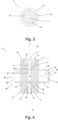
- Figur 1
- einen Querschnitt durch eine Befülleinheit einer Befüllvorrichtung,
- Figur 2
- einen Querschnitt durch den Grundkörper der Befülleinheit gemäß dem Beispiel aus
Figur 1 . - Figur 3
- eine Draufsicht auf die Befülleinheit der Befüllvorrichtung gemäß dem Beispiel aus
Figur 1 . - Figur 4
- einen Querschnitt durch eine Befüllvorrichtung mit an dieser angeordnetem Vorrats- und Aufnahmebehältnis gemäß dem Beispiel aus
Figur 1 , - Figur 5
- eine Draufsicht auf ein erfindungsgemäßes Ausführungsbeispiel einer Befülleinheit einer Befüllvorrichtung,
- Figur 6
- einen Querschnitt durch die Befülleinheit der Befüllvorrichtung gemäß dem erfindungsgemäßen Ausführungsbeispiel,
- Figur 7
- eine schematische Darstellung der Befülleinheit in einer als Einlassstellung bezeichneten Schaltstellung,
- Figur 8
- eine schematische Darstellung der Befülleinheit in einer als Auslassstellung bezeichneten Schaltstellung,
- Figur 9
- eine schematische Darstellung der Befülleinheit in einer als Schließstellung bezeichneten Schaltstellung,
- Figur 10
- einen Querschnitt durch ein erstes Ausführungsbeispiel einer Befülleinheit einer Befüllvorrichtung mit einem als Hohlzylinder ausgebildeten Einsatz als Volumeneinstelleinrichtung,
- Figur 11
- einen Querschnitt durch ein erstes Ausführungsbeispiel einer Befülleinheit einer Befüllvorrichtung mit einer durch einen Aktivierungsmechanismus partiell einstellbaren Wand des Dosierkanalabschnitts als Volumeneinstelleinrichtung.
- Sofern keine anderslautenden Angaben gemacht werden, bezieht sich die nachfolgende Beschreibung auf sämtliche in der Zeichnung illustrierten Ausführungsformen einer erfindungsgemäßen Befüllvorrichtung 1 zur Dosierung einer definierten Menge an schüttgutartigem Material.
- Die Befüllvorrichtung 1 umfasst eine Befülleinheit 2 mit einem um eine Drehachse 3 rotationssymmetrischen Grundkörper 4 und einer zwei Steuerungsarme 5 aufweisenden Steuerungseinrichtung 6.
- Der Grundkörper 4 ist von mindestens einem in Achsrichtung der Drehachse 3 verlaufenden, einen Einlassabschnitt 7, einen ein exakt definiertes Volumen 8 aufweisenden Dosierkanalabschnitt 9 und einen Auslassabschnitt 10 umfassenden Dosierkanal 11 durchsetzt. Jeder Dosierkanal 11 weist einen Dosierkanalabschnitteinlass 12 und einen Dosierkanalabschnittauslass 13 auf. Der Dosierkanal 11 erstreckt sich in gerader Form entlang der Drehachse 3.
- Der Grundkörper 4 umfasst an einem ersten Ende 14 eine erste Aufnahmeeinheit 15 für ein an der Befülleinheit 2 anordenbares Vorratsbehältnis 16, insbesondere ein Probennahmeglas, für schüttgutartiges Material. An einem dem ersten Ende 14 entgegengesetzten Ende 17 umfasst der Grundkörper 4 eine zweite Aufnahmeeinheit 18 für ein an der Befülleinheit 2 anordenbares Aufnahmebehältnis 19 für schüttgutartiges Material. Die erste Aufnahmeeinheit 15 weist ein als bevorzugte Ausführungsform ein Gewinde 20 zur Anordnung des Vorratsbehältnisses 16 für schüttgutartiges Material auf. Dementsprechend wird das Vorratsbehältnis 16 mit der Befülleinheit 2 verschraubt. Im Gegensatz hierzu weist die zweite Aufnahmeeinheit 18 als bevorzugte Ausführungsform eine Passung 21 für das Aufnahmebehältnisses 19 für schüttgutartiges Material auf. Somit wird das Aufnahmebehältnis 18, beispielsweise ein Reagenzglas oder ein Strohhalm in die Aufnahmeeinheit 18 geklemmt.
- Die Aufnahmeeinheiten 15 und 18 sind in den gezeigten Ausführungsbeispielen senkrecht zur Drehachse 3 angeordnet. Andere Ausführungsvarianten, wie winkelig zur Drehachse 3 sind nicht illustriert.
- In anderen nicht illustrierten Ausführungsbeispielen sind die Aufnahmeeinheiten 15, 18 jeweils als Gewinde 20 oder jeweils als Passung 21 ausgebildet.
- Zudem verfügt der Grundkörper 4 über zwei Steuerungsarmführungen 22 zur Aufnahme der verschiebbar in diesen angeordneten Steuerungsarme 5 der Steuerungseinrichtung 6. Die zwei Steuerungsarmführungen 22 sind jeweils rechtwinklig zum Dosierkanal 11 angeordnet.
- Hierbei weist der erste Steuerungsarm 5a eine dem Dosierkanalabschnitteinlass 12 zugeordnete Dosierkanalabschnitteinlassöffnung 23 und der zweite Steuerungsarm 5b eine dem Dosierkanalabschnittauslass 13 zugeordnete Dosierkanalabschnittauslassöffnung 24 auf. Die Steuerungsarme 5a und 5b sind bevorzugt parallel zueinander ausgebildet.
- Die Steuerungseinrichtung 6 ist durch Verschieben wahlweise in unterschiedliche Schaltstellungen 25 verbringbar. Als Schaltstellungen 25 ergeben sich eine Einlassstellung 26, eine Auslassstellung 27 oder eine Schließstellung 28.
- In
Fig. 7 wird eine schematische Darstellung der Befülleinheit 2 in einer als Einlassstellung 26 bezeichneten Schaltstellung 25 gezeigt. Hierbei gibt beim Verbringen des ersten Steuerungsarms 5a der Steuerungseinrichtung 6 die Dosierkanalabschnitteinlassöffnung 23 den ihr zugeordneten Dosierkanalabschnitteinlass 12 zur Befüllung des Dosierkanals 11 frei und gleichzeitig wird der Dosierkanalabschnittauslass 13 durch den zweiten Steuerungsarms 5b der Steuerungseinrichtung 6 verschlossen. - Eine weitere Schaltstellung 25 wird mit einer schematischen Darstellung der Befülleinheit 2 in einer als Auslassstellung 27 bezeichneten Schaltstellung 25 in
Fig. 8 dargestellt. Beim Verbringen der Steuerungseinrichtung 6 in die Auslassstellung 27 wird der Dosierkanalabschnitteinlass 12 durch den ersten Steuerungsarm 5a verschlossen und gleichzeitig gibt die im zweiten Steuerungsarm 5b angeordnete Dosierkanalabschnittauslassöffnung 24 den ihr zugeordneten Dosierkanalabschnittauslass 13 frei. -
Fig. 9 zeigt die als Schließstellung 28 bezeichnete Schaltstellung 25, wobei beim Verbringen der Steuerungseinrichtung 6 in die Schließstellung 28 sowohl Dosierkanalabschnitteinlass 12 als auch der Dosierkanalabschnittauslass 13 durch die Steuerungsarme 5 der Steuerungseinrichtung 6 verschlossen sind. - Zweckmäßig weist die Befülleinheit 2 eine Kraftspeichereinrichtung 29 auf. Bevorzugt ist die Kraftspeichereinrichtung 29 als Federelement 30, bevorzugt als eine Schraubenfeder 31, ausgebildet. In einem nicht illustrierten Ausführungsbeispiel ist die Kraftspeichereinrichtung 29 als Dämpfer ausgebildet.
- Die Kraftspeichereinrichtung 29 ist bevorzugt derart zwischen Grundkörper 4 und Steuerungseinrichtung 6 angeordnet, dass die Steuerungseinrichtung 6 in eine Grundstellung 32 vorgespannt ist. Hierbei ist die Grundstellung 32 die Einlassstellung 26 oder die Schließstellung 28.
- Gemäß einem weiteren in
Fig. 5 dargestellten erfindungsgemäßen Ausführungsbeispiel ist der Grundkörper 4 mehrteilig ausgebildet. Hierbei weist der Grundkörper 4 einen um die Drehachse 3 drehbaren Dosierkanalkörper 33 auf, der über eine Vielzahl an Dosierkanalabschnitten 9 mit unterschiedlichen definierten Volumina 8 verfügt. Der Dosierkanalkörper 33 wird relativ zum Grundkörper-Innenteil 4a um die Drehachse 3 gedreht. Im Ausführungsbeispiel hat der Dosierkanalkörper 33 fünf Dosierkanalabschnitte 9, jeweils mit einem unterschiedlich großen definierten Volumen 8. Die Volumina 8 der Dosierkanalabschnitte 9 sind bevorzugt von sehr kleinen Mengen an schüttgutartigem Material im Bereich von Nanogramm bis hin zu mehreren Gramm ausführbar. Die fünf Dosierkanalabschnitte 9 sind in Umfangsrichtung in dem Dosierkanalkörper 33 angeordnet, wobei diese in einem Winkel von 45° voneinander beabstandet sind. - In
Fig. 5 verlaufen der Einlassabschnitt 7 und der Auslassabschnitt 10 eine kurze Strecke lang entlang der Drehachse 3 bevor sie schräg radial nach außen weiterverlaufen. Der im Dosierkanalkörper 33 angeordnete Dosierkanalabschnitt 9 verläuft parallel zur Drehachse 3. - Jeder der unterschiedlichen Dosierkanalabschnitte 9 mit einem definierten Volumen 8 ist durch Drehen um die Drehachse 3 im Dosierkanal 11 des Grundkörpers 4 verrastbar. Hierzu weist der ein Grundkörper-Innenteil 4a als Rastnasen 34 ausgebildete Erhebungen 35 auf und der Dosierkanalkörper 33 die den Erhebungen 35 entsprechenden Vertiefungen 36. Durch den durch die Erhebungen 35 und Vertiefungen 36 ausgebildeten Rastmechanismus wird stets ein bündiges Verrasten des Dosierkanalabschnitts 9 im Dosierkanal 11 sichergestellt, sodass ein Befüllen des Dosierkanalabschnitts 9 mit schüttgutartigem Material erfolgen kann. Die Drehung des Dosierkanalkörpers 33 kann manuell oder elektrisch betrieben erfolgen.
- In
Fig. 10 wird ein Ausführungsbeispiel einer Befüllvorrichtung 1 dargestellt, wobei im Gegensatz zu der inFig. 1 gezeigten Befüllvorrichtung 1 im Dosierkanalabschnitt 9 ein als Hohlzylinder 37 ausgebildeter Einsatz 38 einer Volumeneinstelleinrichtung 39 ist. Durch den eine Wandstärke 40 aufweisenden Hohlzylinder 37 wird das definierte Volumen 8 im Dosierkanalabschnitt 9 verändert und ist daher einstellbar. Auch mehrere Einsätze 38 in Form von Hohlzylindern 37 sind denkbar. Durch das Einbringen von Hohlzylindern 37 mit unterschiedlicher Wandstärke 38 kann das Volumen 8 exakt an das geforderte Volumen angepasst werden. - Darüber hinaus bevorzugt ist die Volumeneinstelleinrichtung 39 als eine zumindest partiell durch einen Aktivierungsmechanismus 41 einstellbare Wandung 42 des Dosierkanalabschnitts 11 ausgebildet. Diese Ausführungsform ist in
Fig. 11 dargestellt. Als Aktivierungsvorrichtung 41 dient beispielsweise eine Schraube. Entsprechend der Drehrichtung der Schraube wird das Volumen 8 des Dosierkanalabschnitts 9 kleiner oder größer.
Claims (10)
- Befüllvorrichtung (1) zur Dosierung einer definierten Menge an schüttgutartigem Material, wobei die Befüllvorrichtung (1) eine Befülleinheit (2) mit einem um eine Drehachse (3) rotationssymmetrischen Grundkörper (4) und einer zwei Steuerungsarme (5) aufweisenden Steuerungseinrichtung (6) aufweist, wobei der Grundkörper (4) von mindestens einem in Achsrichtung der Drehachse (3) verlaufenden, einen Einlassabschnitt (7), einen ein definiertes Volumen (8) aufweisenden Dosierkanalabschnitt (9) und einen Auslassabschnitt (10) umfassenden Dosierkanal (11) durchsetzt ist, wobei jeder Dosierkanal (11) einen Dosierkanalabschnitteinlass (12) und einen Dosierkanalabschnittauslass (13) aufweist, und wobei der Grundkörper (4) an einem ersten Ende (14) eine erste Aufnahmeeinheit (15) für ein an der Befülleinheit (2) anordenbares Vorratsbehältnis (16) für schüttgutartiges Material und an einem dem ersten Ende (14) entgegengesetzten Ende (17) eine zweite Aufnahmeeinheit (18) für ein an der Befülleinheit (2) anordenbares Aufnahmebehältnis (19) für schüttgutartiges Material umfasst, und wobei der Grundkörper (4) über zwei Steuerungsarmführungen (22) zur Aufnahme der verschiebbar in diesen angeordneten Steuerungsarme (5) der Steuerungseinrichtung (6) verfügt, wobei der erste Steuerungsarm (5a) eine dem Dosierkanalabschnitteinlass (12) zugeordnete Dosierkanalabschnitteinlassöffnung (23) und der zweite Steuerungsarm (5b) eine dem Dosierkanalabschnittauslass (13) zugeordnete Dosierkanalabschnittauslassöffnung (24) aufweist, und wobei die Steuerungseinrichtung (6) durch Verschieben wahlweise in unterschiedliche Schaltstellungen (25) verbringbar ist, wobei die Schaltstellung (25) eine Einlassstellung (26) ist, in der beim Verbringen der Steuerungseinrichtung (6) die Dosierkanalabschnitteinlassöffnung (23) den ihr zugeordneten Dosierkanalabschnitteinlass (12) zur Befüllung des Dosierkanals (11) freigibt und gleichzeitig der Dosierkanalabschnittauslass (13) verschlossen wird, und wobei die Schaltstellung (25) eine Auslassstellung (27) ist, in der beim Verbringen der Steuerungseinrichtung (6) der Dosierkanalabschnitteinlass (12) verschlossen wird und gleichzeitig die Dosierkanalabschnittauslassöffnung (24) den ihr zugeordneten Dosierkanalabschnittauslass (13) freigibt, und wobei der Grundkörper (4) mehrteilig ausgebildet ist, wobei der Grundkörper (4) einen um die Drehachse (3) drehbaren Dosierkanalkörper (33) aufweist, der über eine Vielzahl an Dosierkanalabschnitten (9) mit unterschiedlichen definierten Volumina (8) verfügt, dadurch gekennzeichnet, dass jeder der unterschiedlichen Dosierkanalabschnitte (9) mit einem definierten Volumen (8) durch Drehen um die Drehachse (3) im Dosierkanal (11) des Grundkörpers (4) verrastbar ist.
- Befüllvorrichtung (1) nach Anspruch 1, dadurch gekennzeichnet, dass die Schaltstellung (25) eine Schließstellung (28) ist, in der beim Verbringen der Steuerungseinrichtung (6) in die Schließstellung (28) der Dosierkanalabschnitteinlass (12) und gleichzeitig der Dosierkanalabschnittauslass (13) verschlossen sind.
- Befüllvorrichtung (1) nach Anspruch 1 oder 2, dadurch gekennzeichnet, dass die Befülleinheit (2) eine Kraftspeichereinrichtung (29) aufweist, die derart zwischen Grundkörper (4) und Steuerungseinrichtung (6) angeordnet ist, dass die Steuerungseinrichtung (6) in eine Grundstellung (32) vorgespannt ist.
- Befüllvorrichtung (1) nach Anspruch 3, dadurch gekennzeichnet, dass die Grundstellung (32) die Einlassstellung (26) oder die Schließstellung (28) ist.
- Befüllvorrichtung (1) nach Anspruch 3 oder 4, dadurch gekennzeichnet, dass die Kraftspeichereinrichtung (29) als Federelement (30), bevorzugt als eine Schraubenfeder (31), ausgebildet ist.
- Befüllvorrichtung (1) nach einem der vorhergehenden Ansprüche, dadurch gekennzeichnet, dass die erste und/oder die zweite Aufnahmeeinheit (15, 18) ein Gewinde (20) oder eine Passung (21) zur Anordnung des Vorratsbehältnisses (16) für schüttgutartiges Material und/oder des Aufnahmebehältnisses (19) für schüttgutartiges Material umfassen.
- Befüllvorrichtung (1) nach einem der vorhergehenden Ansprüche, dadurch gekennzeichnet, dass die Befüllvorrichtung (1) eine das definierte Volumen (8) des Dosierkanalabschnitts (9) einstellbare Volumeneinstelleinrichtung (39) aufweist.
- Befüllvorrichtung (1) nach Anspruch 7, dadurch gekennzeichnet, dass die Volumeneinstelleinrichtung (39) als mindestes ein in den Dosierkanalabschnitt (9) des Dosierkanals (11) einbringbarer Einsatz (38) ausgebildet ist.
- Befüllvorrichtung (1) nach Anspruch 8, dadurch gekennzeichnet, dass der mindestens eine Einsatz (38) als ein eine Wandstärke (40) aufweisender Hohlzylinder (37) ausgebildet ist.
- Befüllvorrichtung (1) nach Anspruch 9, dadurch gekennzeichnet, dass die Volumeneinstelleinrichtung (39) als eine zumindest partiell durch einen Aktivierungsmechanismus (41) einstellbare Wandung (42) des Dosierkanalabschnitts (9) ausgebildet ist.
Applications Claiming Priority (2)
| Application Number | Priority Date | Filing Date | Title |
|---|---|---|---|
| DE102019219020.0A DE102019219020A1 (de) | 2019-12-06 | 2019-12-06 | Befüllvorrichtung |
| PCT/EP2020/082203 WO2021110394A1 (de) | 2019-12-06 | 2020-11-16 | Befüllvorrichtung |
Publications (2)
| Publication Number | Publication Date |
|---|---|
| EP4070046A1 EP4070046A1 (de) | 2022-10-12 |
| EP4070046B1 true EP4070046B1 (de) | 2024-05-08 |
Family
ID=73497721
Family Applications (1)
| Application Number | Title | Priority Date | Filing Date |
|---|---|---|---|
| EP20810881.1A Active EP4070046B1 (de) | 2019-12-06 | 2020-11-16 | Befüllvorrichtung |
Country Status (6)
| Country | Link |
|---|---|
| US (2) | US12188803B2 (de) |
| EP (1) | EP4070046B1 (de) |
| CN (1) | CN114729830A (de) |
| DE (1) | DE102019219020A1 (de) |
| ES (1) | ES2982713T3 (de) |
| WO (1) | WO2021110394A1 (de) |
Family Cites Families (26)
| Publication number | Priority date | Publication date | Assignee | Title |
|---|---|---|---|---|
| DE79533C (de) * | ||||
| DE498722C (de) * | 1928-07-03 | 1930-05-24 | Friedrich Bracht | Abfuellvorrichtung fuer Mehl |
| US1891038A (en) * | 1930-03-24 | 1932-12-13 | Barros Ramon | Automatic filler |
| US2318725A (en) * | 1941-11-17 | 1943-05-11 | E H Clements | Sacking and measuring device |
| GB801949A (en) * | 1955-08-18 | 1958-09-24 | Hesser Ag Maschf | Apparatus for measuring out and discharging fluent solid bulk material |
| US4006842A (en) * | 1974-05-03 | 1977-02-08 | Bassignani Anthony L | Material measuring and dispensing device |
| JPS5294850U (de) * | 1976-01-13 | 1977-07-15 | ||
| JPS5294850A (en) | 1976-02-05 | 1977-08-09 | Kobe Steel Ltd | Method of indicating back cutting position of large forging ingot |
| US4109835A (en) | 1976-08-12 | 1978-08-29 | Castro Genaro Afalla | Device for dispensing measured quantities of material |
| DE8900871U1 (de) * | 1989-01-26 | 1990-06-07 | Coffee Team Kaffeemaschinen GmbH, 7187 Schrozberg | Dosiervorrichtung |
| US5855300A (en) * | 1995-08-24 | 1999-01-05 | Malki; Avraham | Device for dispensing a predetermined amount of solids |
| US5746355A (en) * | 1996-03-15 | 1998-05-05 | Cargill, Incorporated | Dispenser for pulverulent material |
| DE19953228A1 (de) * | 1999-11-04 | 2001-05-10 | Basf Ag | Einrichtung zum Dosieren eines granulatförmigen Materials |
| US6550640B2 (en) * | 2001-03-12 | 2003-04-22 | William G. Smith | Method and apparatus for controllably dispensing powders and liquids |
| WO2004003486A1 (en) * | 2002-06-28 | 2004-01-08 | Sirie Price Palmos | Particulate material dispenser |
| US20070228083A1 (en) * | 2004-09-30 | 2007-10-04 | Catani Steven J | Apparatus and method for dispensing precisely controlled amounts of powdered material |
| US8366027B2 (en) * | 2007-09-14 | 2013-02-05 | Restaurant Technology, Inc. | Adjustable metered material dispenser |
| NZ590618A (en) * | 2008-08-14 | 2012-10-26 | Astrazeneca Ab | Dosing device and method for filling a cavity |
| GB2463655B (en) | 2008-09-18 | 2014-04-02 | Anthony Martin Gardiner | Portable applicator for dispensing powder |
| CN201393951Y (zh) * | 2009-02-24 | 2010-02-03 | 黄棣苍 | 调味料容器 |
| US20100193548A1 (en) | 2010-03-08 | 2010-08-05 | Poreda Stanley J | Personal powder dispenser |
| CN201934021U (zh) * | 2011-01-14 | 2011-08-17 | 宁波天工凌屹工具有限公司 | 钻孔导向器 |
| US20140144926A1 (en) | 2012-11-25 | 2014-05-29 | Gilad Wolf | Powder dispenser |
| CN103299748B (zh) * | 2013-07-02 | 2016-08-10 | 苏州绿点园艺技术有限公司 | 手工点种器 |
| CN104472386B (zh) * | 2014-11-03 | 2016-08-17 | 宁波大学 | 一种饲料投喂装置 |
| DE102018003945A1 (de) * | 2018-05-15 | 2019-11-21 | Valentin Muckle | Hand-Dosiervorrichtrung für Pulver- und/oder granulatförmige Nahrungsmittel |
-
2019
- 2019-12-06 DE DE102019219020.0A patent/DE102019219020A1/de not_active Withdrawn
-
2020
- 2020-11-16 WO PCT/EP2020/082203 patent/WO2021110394A1/de not_active Ceased
- 2020-11-16 ES ES20810881T patent/ES2982713T3/es active Active
- 2020-11-16 EP EP20810881.1A patent/EP4070046B1/de active Active
- 2020-11-16 US US17/782,407 patent/US12188803B2/en active Active
- 2020-11-16 CN CN202080084345.3A patent/CN114729830A/zh active Pending
-
2024
- 2024-12-05 US US18/970,084 patent/US20250093191A1/en active Pending
Also Published As
| Publication number | Publication date |
|---|---|
| DE102019219020A1 (de) | 2021-06-10 |
| US20250093191A1 (en) | 2025-03-20 |
| EP4070046A1 (de) | 2022-10-12 |
| US12188803B2 (en) | 2025-01-07 |
| ES2982713T3 (es) | 2024-10-17 |
| CN114729830A (zh) | 2022-07-08 |
| WO2021110394A1 (de) | 2021-06-10 |
| US20230012062A1 (en) | 2023-01-12 |
Similar Documents
| Publication | Publication Date | Title |
|---|---|---|
| DE69116670T2 (de) | Verfahren und Vorrichtung zur Durchflussregelung | |
| DE4200701B4 (de) | Maschine zum Dosieren pulverförmiger Pharmazeutika | |
| DE69219670T2 (de) | Niveauregelventil für Luftfedern | |
| EP2369311B1 (de) | Dosiereinheit für fliessfähige Substanzen | |
| DE3146541A1 (de) | Dosiervorrichtung | |
| EP0399947B1 (de) | Volumenmess- und Dosiereinrichtung | |
| DE2641549A1 (de) | Steuer- und abfuelleinrichtung fuer abfuellmaschinen | |
| DE3324308A1 (de) | Verteilerhahn | |
| DE69116355T2 (de) | Prozedur zum verriegeln der verstellvorrichtung einer pipette, und pipette | |
| DE102005046627A1 (de) | Dosiereinheit zum Dosieren eines Substrats | |
| DE3031284A1 (de) | Durchflussmesser. | |
| DE3020203C2 (de) | Vorrichtung zum Herstellen eines Reaktionsgemisches aus Massiv oder Schaumstoff bildenden fließfähigen Komponenten | |
| DE1675471B2 (de) | Mischventil mit zwei voneinander unabhaengigen bedienungsgriffen | |
| EP4070046A1 (de) | Befüllvorrichtung | |
| DE1268402B (de) | Geraet zur Verteilung vorbestimmter Mengen von fliessendem Material | |
| DE102018003945A1 (de) | Hand-Dosiervorrichtrung für Pulver- und/oder granulatförmige Nahrungsmittel | |
| EP0008278B1 (de) | Bremseinrichtung, insbesondere für Türschliesser | |
| EP3053427A1 (de) | Pneumatische sämaschine | |
| WO2006015644A1 (de) | Einleitungsverteiler | |
| DE3932202A1 (de) | Vorrichtung zur diskontinuierlichen entnahme von proben aus einer produktleitung einer verfahrenstechnischen anlage | |
| EP1196248B1 (de) | Umschaltdüsenkopf für ein hochdruckreinigungsgerät | |
| DE20001101U1 (de) | Strahlrohr für ein Hochdruckreinigungsgerät | |
| EP2885088B1 (de) | Austragvorrichtung | |
| EP1506923B1 (de) | Dosiervorrichtung | |
| DE3422521A1 (de) | Vorrichtung zur volumetrischen abgabe von schuettgut |
Legal Events
| Date | Code | Title | Description |
|---|---|---|---|
| STAA | Information on the status of an ep patent application or granted ep patent |
Free format text: STATUS: UNKNOWN |
|
| STAA | Information on the status of an ep patent application or granted ep patent |
Free format text: STATUS: THE INTERNATIONAL PUBLICATION HAS BEEN MADE |
|
| PUAI | Public reference made under article 153(3) epc to a published international application that has entered the european phase |
Free format text: ORIGINAL CODE: 0009012 |
|
| STAA | Information on the status of an ep patent application or granted ep patent |
Free format text: STATUS: REQUEST FOR EXAMINATION WAS MADE |
|
| 17P | Request for examination filed |
Effective date: 20220427 |
|
| AK | Designated contracting states |
Kind code of ref document: A1 Designated state(s): AL AT BE BG CH CY CZ DE DK EE ES FI FR GB GR HR HU IE IS IT LI LT LU LV MC MK MT NL NO PL PT RO RS SE SI SK SM TR |
|
| DAV | Request for validation of the european patent (deleted) | ||
| DAX | Request for extension of the european patent (deleted) | ||
| P01 | Opt-out of the competence of the unified patent court (upc) registered |
Effective date: 20230519 |
|
| GRAP | Despatch of communication of intention to grant a patent |
Free format text: ORIGINAL CODE: EPIDOSNIGR1 |
|
| STAA | Information on the status of an ep patent application or granted ep patent |
Free format text: STATUS: GRANT OF PATENT IS INTENDED |
|
| INTG | Intention to grant announced |
Effective date: 20240110 |
|
| GRAS | Grant fee paid |
Free format text: ORIGINAL CODE: EPIDOSNIGR3 |
|
| GRAA | (expected) grant |
Free format text: ORIGINAL CODE: 0009210 |
|
| STAA | Information on the status of an ep patent application or granted ep patent |
Free format text: STATUS: THE PATENT HAS BEEN GRANTED |
|
| AK | Designated contracting states |
Kind code of ref document: B1 Designated state(s): AL AT BE BG CH CY CZ DE DK EE ES FI FR GB GR HR HU IE IS IT LI LT LU LV MC MK MT NL NO PL PT RO RS SE SI SK SM TR |
|
| REG | Reference to a national code |
Ref country code: GB Ref legal event code: FG4D Free format text: NOT ENGLISH |
|
| REG | Reference to a national code |
Ref country code: CH Ref legal event code: EP |
|
| REG | Reference to a national code |
Ref country code: DE Ref legal event code: R096 Ref document number: 502020007958 Country of ref document: DE |
|
| REG | Reference to a national code |
Ref country code: IE Ref legal event code: FG4D Free format text: LANGUAGE OF EP DOCUMENT: GERMAN |
|
| REG | Reference to a national code |
Ref country code: SE Ref legal event code: TRGR |
|
| REG | Reference to a national code |
Ref country code: LT Ref legal event code: MG9D |
|
| REG | Reference to a national code |
Ref country code: NL Ref legal event code: MP Effective date: 20240508 |
|
| PG25 | Lapsed in a contracting state [announced via postgrant information from national office to epo] |
Ref country code: IS Free format text: LAPSE BECAUSE OF FAILURE TO SUBMIT A TRANSLATION OF THE DESCRIPTION OR TO PAY THE FEE WITHIN THE PRESCRIBED TIME-LIMIT Effective date: 20240908 |
|
| PG25 | Lapsed in a contracting state [announced via postgrant information from national office to epo] |
Ref country code: BG Free format text: LAPSE BECAUSE OF FAILURE TO SUBMIT A TRANSLATION OF THE DESCRIPTION OR TO PAY THE FEE WITHIN THE PRESCRIBED TIME-LIMIT Effective date: 20240508 |
|
| PG25 | Lapsed in a contracting state [announced via postgrant information from national office to epo] |
Ref country code: FI Free format text: LAPSE BECAUSE OF FAILURE TO SUBMIT A TRANSLATION OF THE DESCRIPTION OR TO PAY THE FEE WITHIN THE PRESCRIBED TIME-LIMIT Effective date: 20240508 Ref country code: HR Free format text: LAPSE BECAUSE OF FAILURE TO SUBMIT A TRANSLATION OF THE DESCRIPTION OR TO PAY THE FEE WITHIN THE PRESCRIBED TIME-LIMIT Effective date: 20240508 |
|
| PG25 | Lapsed in a contracting state [announced via postgrant information from national office to epo] |
Ref country code: GR Free format text: LAPSE BECAUSE OF FAILURE TO SUBMIT A TRANSLATION OF THE DESCRIPTION OR TO PAY THE FEE WITHIN THE PRESCRIBED TIME-LIMIT Effective date: 20240809 |
|
| PG25 | Lapsed in a contracting state [announced via postgrant information from national office to epo] |
Ref country code: PT Free format text: LAPSE BECAUSE OF FAILURE TO SUBMIT A TRANSLATION OF THE DESCRIPTION OR TO PAY THE FEE WITHIN THE PRESCRIBED TIME-LIMIT Effective date: 20240909 |
|
| PG25 | Lapsed in a contracting state [announced via postgrant information from national office to epo] |
Ref country code: NL Free format text: LAPSE BECAUSE OF FAILURE TO SUBMIT A TRANSLATION OF THE DESCRIPTION OR TO PAY THE FEE WITHIN THE PRESCRIBED TIME-LIMIT Effective date: 20240508 |
|
| REG | Reference to a national code |
Ref country code: ES Ref legal event code: FG2A Ref document number: 2982713 Country of ref document: ES Kind code of ref document: T3 Effective date: 20241017 |
|
| PG25 | Lapsed in a contracting state [announced via postgrant information from national office to epo] |
Ref country code: PL Free format text: LAPSE BECAUSE OF FAILURE TO SUBMIT A TRANSLATION OF THE DESCRIPTION OR TO PAY THE FEE WITHIN THE PRESCRIBED TIME-LIMIT Effective date: 20240508 |
|
| PG25 | Lapsed in a contracting state [announced via postgrant information from national office to epo] |
Ref country code: LV Free format text: LAPSE BECAUSE OF FAILURE TO SUBMIT A TRANSLATION OF THE DESCRIPTION OR TO PAY THE FEE WITHIN THE PRESCRIBED TIME-LIMIT Effective date: 20240508 |
|
| PG25 | Lapsed in a contracting state [announced via postgrant information from national office to epo] |
Ref country code: PT Free format text: LAPSE BECAUSE OF FAILURE TO SUBMIT A TRANSLATION OF THE DESCRIPTION OR TO PAY THE FEE WITHIN THE PRESCRIBED TIME-LIMIT Effective date: 20240909 Ref country code: PL Free format text: LAPSE BECAUSE OF FAILURE TO SUBMIT A TRANSLATION OF THE DESCRIPTION OR TO PAY THE FEE WITHIN THE PRESCRIBED TIME-LIMIT Effective date: 20240508 Ref country code: NO Free format text: LAPSE BECAUSE OF FAILURE TO SUBMIT A TRANSLATION OF THE DESCRIPTION OR TO PAY THE FEE WITHIN THE PRESCRIBED TIME-LIMIT Effective date: 20240808 Ref country code: NL Free format text: LAPSE BECAUSE OF FAILURE TO SUBMIT A TRANSLATION OF THE DESCRIPTION OR TO PAY THE FEE WITHIN THE PRESCRIBED TIME-LIMIT Effective date: 20240508 Ref country code: LV Free format text: LAPSE BECAUSE OF FAILURE TO SUBMIT A TRANSLATION OF THE DESCRIPTION OR TO PAY THE FEE WITHIN THE PRESCRIBED TIME-LIMIT Effective date: 20240508 Ref country code: IS Free format text: LAPSE BECAUSE OF FAILURE TO SUBMIT A TRANSLATION OF THE DESCRIPTION OR TO PAY THE FEE WITHIN THE PRESCRIBED TIME-LIMIT Effective date: 20240908 Ref country code: HR Free format text: LAPSE BECAUSE OF FAILURE TO SUBMIT A TRANSLATION OF THE DESCRIPTION OR TO PAY THE FEE WITHIN THE PRESCRIBED TIME-LIMIT Effective date: 20240508 Ref country code: GR Free format text: LAPSE BECAUSE OF FAILURE TO SUBMIT A TRANSLATION OF THE DESCRIPTION OR TO PAY THE FEE WITHIN THE PRESCRIBED TIME-LIMIT Effective date: 20240809 Ref country code: FI Free format text: LAPSE BECAUSE OF FAILURE TO SUBMIT A TRANSLATION OF THE DESCRIPTION OR TO PAY THE FEE WITHIN THE PRESCRIBED TIME-LIMIT Effective date: 20240508 Ref country code: BG Free format text: LAPSE BECAUSE OF FAILURE TO SUBMIT A TRANSLATION OF THE DESCRIPTION OR TO PAY THE FEE WITHIN THE PRESCRIBED TIME-LIMIT Effective date: 20240508 Ref country code: RS Free format text: LAPSE BECAUSE OF FAILURE TO SUBMIT A TRANSLATION OF THE DESCRIPTION OR TO PAY THE FEE WITHIN THE PRESCRIBED TIME-LIMIT Effective date: 20240808 |
|
| PG25 | Lapsed in a contracting state [announced via postgrant information from national office to epo] |
Ref country code: DK Free format text: LAPSE BECAUSE OF FAILURE TO SUBMIT A TRANSLATION OF THE DESCRIPTION OR TO PAY THE FEE WITHIN THE PRESCRIBED TIME-LIMIT Effective date: 20240508 |
|
| PG25 | Lapsed in a contracting state [announced via postgrant information from national office to epo] |
Ref country code: EE Free format text: LAPSE BECAUSE OF FAILURE TO SUBMIT A TRANSLATION OF THE DESCRIPTION OR TO PAY THE FEE WITHIN THE PRESCRIBED TIME-LIMIT Effective date: 20240508 |
|
| PG25 | Lapsed in a contracting state [announced via postgrant information from national office to epo] |
Ref country code: RO Free format text: LAPSE BECAUSE OF FAILURE TO SUBMIT A TRANSLATION OF THE DESCRIPTION OR TO PAY THE FEE WITHIN THE PRESCRIBED TIME-LIMIT Effective date: 20240508 Ref country code: SK Free format text: LAPSE BECAUSE OF FAILURE TO SUBMIT A TRANSLATION OF THE DESCRIPTION OR TO PAY THE FEE WITHIN THE PRESCRIBED TIME-LIMIT Effective date: 20240508 |
|
| PG25 | Lapsed in a contracting state [announced via postgrant information from national office to epo] |
Ref country code: SM Free format text: LAPSE BECAUSE OF FAILURE TO SUBMIT A TRANSLATION OF THE DESCRIPTION OR TO PAY THE FEE WITHIN THE PRESCRIBED TIME-LIMIT Effective date: 20240508 |
|
| PG25 | Lapsed in a contracting state [announced via postgrant information from national office to epo] |
Ref country code: SM Free format text: LAPSE BECAUSE OF FAILURE TO SUBMIT A TRANSLATION OF THE DESCRIPTION OR TO PAY THE FEE WITHIN THE PRESCRIBED TIME-LIMIT Effective date: 20240508 Ref country code: SK Free format text: LAPSE BECAUSE OF FAILURE TO SUBMIT A TRANSLATION OF THE DESCRIPTION OR TO PAY THE FEE WITHIN THE PRESCRIBED TIME-LIMIT Effective date: 20240508 Ref country code: RO Free format text: LAPSE BECAUSE OF FAILURE TO SUBMIT A TRANSLATION OF THE DESCRIPTION OR TO PAY THE FEE WITHIN THE PRESCRIBED TIME-LIMIT Effective date: 20240508 Ref country code: EE Free format text: LAPSE BECAUSE OF FAILURE TO SUBMIT A TRANSLATION OF THE DESCRIPTION OR TO PAY THE FEE WITHIN THE PRESCRIBED TIME-LIMIT Effective date: 20240508 Ref country code: DK Free format text: LAPSE BECAUSE OF FAILURE TO SUBMIT A TRANSLATION OF THE DESCRIPTION OR TO PAY THE FEE WITHIN THE PRESCRIBED TIME-LIMIT Effective date: 20240508 |
|
| REG | Reference to a national code |
Ref country code: DE Ref legal event code: R097 Ref document number: 502020007958 Country of ref document: DE |
|
| PLBE | No opposition filed within time limit |
Free format text: ORIGINAL CODE: 0009261 |
|
| STAA | Information on the status of an ep patent application or granted ep patent |
Free format text: STATUS: NO OPPOSITION FILED WITHIN TIME LIMIT |
|
| 26N | No opposition filed |
Effective date: 20250211 |
|
| PG25 | Lapsed in a contracting state [announced via postgrant information from national office to epo] |
Ref country code: SI Free format text: LAPSE BECAUSE OF FAILURE TO SUBMIT A TRANSLATION OF THE DESCRIPTION OR TO PAY THE FEE WITHIN THE PRESCRIBED TIME-LIMIT Effective date: 20240508 |
|
| PG25 | Lapsed in a contracting state [announced via postgrant information from national office to epo] |
Ref country code: MC Free format text: LAPSE BECAUSE OF FAILURE TO SUBMIT A TRANSLATION OF THE DESCRIPTION OR TO PAY THE FEE WITHIN THE PRESCRIBED TIME-LIMIT Effective date: 20240508 |
|
| PG25 | Lapsed in a contracting state [announced via postgrant information from national office to epo] |
Ref country code: LU Free format text: LAPSE BECAUSE OF NON-PAYMENT OF DUE FEES Effective date: 20241116 |
|
| REG | Reference to a national code |
Ref country code: CH Ref legal event code: U11 Free format text: ST27 STATUS EVENT CODE: U-0-0-U10-U11 (AS PROVIDED BY THE NATIONAL OFFICE) Effective date: 20251201 |
|
| PGFP | Annual fee paid to national office [announced via postgrant information from national office to epo] |
Ref country code: DE Payment date: 20251105 Year of fee payment: 6 |
|
| PGFP | Annual fee paid to national office [announced via postgrant information from national office to epo] |
Ref country code: GB Payment date: 20251120 Year of fee payment: 6 |
|
| PGFP | Annual fee paid to national office [announced via postgrant information from national office to epo] |
Ref country code: AT Payment date: 20251117 Year of fee payment: 6 |
|
| PGFP | Annual fee paid to national office [announced via postgrant information from national office to epo] |
Ref country code: IT Payment date: 20251128 Year of fee payment: 6 |
|
| PGFP | Annual fee paid to national office [announced via postgrant information from national office to epo] |
Ref country code: FR Payment date: 20251125 Year of fee payment: 6 |
|
| PGFP | Annual fee paid to national office [announced via postgrant information from national office to epo] |
Ref country code: TR Payment date: 20251112 Year of fee payment: 6 Ref country code: BE Payment date: 20251118 Year of fee payment: 6 |
|
| PGFP | Annual fee paid to national office [announced via postgrant information from national office to epo] |
Ref country code: SE Payment date: 20251119 Year of fee payment: 6 Ref country code: CH Payment date: 20251201 Year of fee payment: 6 |
|
| PGFP | Annual fee paid to national office [announced via postgrant information from national office to epo] |
Ref country code: IE Payment date: 20251120 Year of fee payment: 6 Ref country code: CZ Payment date: 20251031 Year of fee payment: 6 |
|
| PGFP | Annual fee paid to national office [announced via postgrant information from national office to epo] |
Ref country code: ES Payment date: 20251216 Year of fee payment: 6 |
|
| PG25 | Lapsed in a contracting state [announced via postgrant information from national office to epo] |
Ref country code: HU Free format text: LAPSE BECAUSE OF FAILURE TO SUBMIT A TRANSLATION OF THE DESCRIPTION OR TO PAY THE FEE WITHIN THE PRESCRIBED TIME-LIMIT; INVALID AB INITIO Effective date: 20201116 |
|
| PG25 | Lapsed in a contracting state [announced via postgrant information from national office to epo] |
Ref country code: CY Free format text: LAPSE BECAUSE OF FAILURE TO SUBMIT A TRANSLATION OF THE DESCRIPTION OR TO PAY THE FEE WITHIN THE PRESCRIBED TIME-LIMIT; INVALID AB INITIO Effective date: 20201116 |