EP4069578B1 - Véhicule automobile à becquet de toit - Google Patents
Véhicule automobile à becquet de toit Download PDFInfo
- Publication number
- EP4069578B1 EP4069578B1 EP20811606.1A EP20811606A EP4069578B1 EP 4069578 B1 EP4069578 B1 EP 4069578B1 EP 20811606 A EP20811606 A EP 20811606A EP 4069578 B1 EP4069578 B1 EP 4069578B1
- Authority
- EP
- European Patent Office
- Prior art keywords
- motor vehicle
- outer side
- side panel
- roof spoiler
- roof
- Prior art date
- Legal status (The legal status is an assumption and is not a legal conclusion. Google has not performed a legal analysis and makes no representation as to the accuracy of the status listed.)
- Active
Links
Images


Classifications
-
- B—PERFORMING OPERATIONS; TRANSPORTING
- B62—LAND VEHICLES FOR TRAVELLING OTHERWISE THAN ON RAILS
- B62D—MOTOR VEHICLES; TRAILERS
- B62D35/00—Vehicle bodies characterised by streamlining
- B62D35/001—For commercial vehicles or tractor-trailer combinations, e.g. caravans
-
- B—PERFORMING OPERATIONS; TRANSPORTING
- B60—VEHICLES IN GENERAL
- B60S—SERVICING, CLEANING, REPAIRING, SUPPORTING, LIFTING, OR MANOEUVRING OF VEHICLES, NOT OTHERWISE PROVIDED FOR
- B60S1/00—Cleaning of vehicles
- B60S1/02—Cleaning windscreens, windows or optical devices
- B60S1/46—Cleaning windscreens, windows or optical devices using liquid; Windscreen washers
- B60S1/48—Liquid supply therefor
- B60S1/50—Arrangement of reservoir
-
- B—PERFORMING OPERATIONS; TRANSPORTING
- B62—LAND VEHICLES FOR TRAVELLING OTHERWISE THAN ON RAILS
- B62D—MOTOR VEHICLES; TRAILERS
- B62D33/00—Superstructures for load-carrying vehicles
- B62D33/06—Drivers' cabs
-
- B—PERFORMING OPERATIONS; TRANSPORTING
- B60—VEHICLES IN GENERAL
- B60Y—INDEXING SCHEME RELATING TO ASPECTS CROSS-CUTTING VEHICLE TECHNOLOGY
- B60Y2200/00—Type of vehicle
- B60Y2200/10—Road Vehicles
- B60Y2200/14—Trucks; Load vehicles, Busses
-
- Y—GENERAL TAGGING OF NEW TECHNOLOGICAL DEVELOPMENTS; GENERAL TAGGING OF CROSS-SECTIONAL TECHNOLOGIES SPANNING OVER SEVERAL SECTIONS OF THE IPC; TECHNICAL SUBJECTS COVERED BY FORMER USPC CROSS-REFERENCE ART COLLECTIONS [XRACs] AND DIGESTS
- Y02—TECHNOLOGIES OR APPLICATIONS FOR MITIGATION OR ADAPTATION AGAINST CLIMATE CHANGE
- Y02T—CLIMATE CHANGE MITIGATION TECHNOLOGIES RELATED TO TRANSPORTATION
- Y02T10/00—Road transport of goods or passengers
- Y02T10/80—Technologies aiming to reduce greenhouse gasses emissions common to all road transportation technologies
- Y02T10/82—Elements for improving aerodynamics
Definitions
- the invention relates to a motor vehicle, preferably a commercial vehicle, with a roof spoiler.
- the height adjustment allows the roof spoiler to be aligned relative to the front upper edge of a loading body, semitrailer, or trailer.
- the height adjustment is traditionally performed manually on the rear wall of the truck's cab.
- the windshield cleaning system may include cleaning nozzles, a pump, and a tank.
- the cleaning nozzles are directed at the windshield and can be supplied with cleaning fluid from the tank by the pump. Space must be provided for the tank. Easy access to the tank for filling is also advantageous.
- brackets for height-adjustable roof spoilers are, for example, from the EP 2 020 366 A2 and the EP 1 055 589 A2 known.
- DE 10 2014 017 732 A1 discloses a tractor with two side wind deflectors and a fluid tank, preferably a reducing agent tank, located between them.
- a tractor and a trailer are known which are coupled together in a tandem towing relationship.
- An air deflector system is attached to the tractor to aerodynamically reduce the drag of such a combination by enclosing a space between a cab of the tractor and the trailer.
- a bracket is attached to a support device of the tractor.
- An upper air fairing is movably attached to the support device and extends from the top of the cab to the top of the trailer.
- Two side fairings are movably attached to the support device and extend from the rear of the cab to the trailer, the side fairings mating with the upper fairing.
- a means is provided for adjusting the fairings depending to move from one position to another after alignment between the trailer and the tractor.
- the WO 2007/090172 A2 discloses an air shield comprising a sidewall assembly in pivotal connection with each rear edge of a tractor sidewall and an actuation assembly.
- the actuation assembly includes a hub in rotational engagement with the frame of the tractor, the hub being disposed between a cab and a fifth wheel of the tractor.
- the actuation assembly further includes a lever having an adjustable length engaging the hub at a first end and the sidewall assembly at a second end.
- the actuation assembly further includes a spring having a first end connected to the sidewall assembly and a second end connected to the frame of the tractor between the hub and the rear of a trailer frame.
- the US 4,779,915 A discloses an air foil system for removably, adjustably mounting to a frame of a tractor behind the cab for reducing the aerodynamic drag experienced by a trailer pulled by the tractor.
- the air foil system comprises an upright support member including fasteners at its base adapted to removably secure the support member to the frame of the tractor behind the cab, the support member having a transverse dimension approximately equal to the width of the cab.
- the air foil system further comprises an air foil adjustably mounted on top of the support member, the air foil adapted to extend over the cab.
- the air foil system further comprises an adjustable side wall attached to each end of the support member, each side wall extending downwardly from the top of the support member toward the base. Each side wall has a height greater than its width.
- the US 6,428,084 B1 discloses a fuel-efficient tractor-trailer system for improving the fuel consumption of a tractor-trailer combination by improving the drag experienced in the area between the rear of the tractor and the front of the trailer.
- the fuel-efficient tractor-trailer system features an improved roof extension that automatically raises when the tractor is shifted into reverse, as well as an improved wheel mechanism that assists the sliding of the side extensions around the ends of the trailer when the tractor and trailer turn.
- the invention is based on the object of creating an alternative and/or improved motor vehicle with a roof spoiler, and preferably additionally with a windscreen cleaning system.
- a motor vehicle preferably a commercial vehicle (e.g., a truck), is disclosed.
- the motor vehicle has a body and an outer side panel, which is arranged on a longitudinal outer side of the motor vehicle and is movable between a closed position and an open position, preferably pivotable, connected to the body (e.g., directly or indirectly).
- the motor vehicle has a (e.g., pivotable) roof spoiler and an (e.g., manual) adjustment device by means of which the roof spoiler can be adjusted in height.
- the adjustment device is concealed behind the outer side panel.
- the adjustment device is accessible from the outside.
- the body has a longitudinal side wall, and the adjusting device is arranged and/or fastened to the longitudinal side wall.
- the longitudinal side wall can be aligned parallel to a longitudinal axis of the motor vehicle and/or can be concealed by the outer side panel in the closed position of the outer side panel and accessible from the outside in the open position of the outer side panel.
- the adjustment device comprises a (e.g., vertically oriented) rail by means of which the roof spoiler is height-adjustable.
- the rail can preferably be configured as an elongated hole and/or comprise a plurality of superimposed (e.g., serrated, claw-shaped, or tooth-shaped) projections to which the roof spoiler can be detachably attached indirectly (e.g., by means of an elongated connecting element), preferably by means of a screw connection.
- the motor vehicle further comprises an elongated (e.g., rod-shaped, tubular, or beam-shaped) connecting element that connects the roof spoiler to the adjustment device in a height-adjustable manner and is preferably pivotably connected to the roof spoiler.
- the motor vehicle may further comprise a trim panel arranged between the roof spoiler and the outer side panel, wherein the elongated connecting element is arranged at least partially concealed behind the trim panel.
- the body has a roof with a recess (e.g. roof ditch), and a leading edge of the roof spoiler emerges when the vehicle is raised of the roof spoiler into the recess, e.g., increasingly. This can improve the airflow to the roof spoiler.
- a recess e.g. roof ditch
- the roof spoiler can be adjusted to a substantially vertical orientation for installation or removal using the adjustment device. This can, for example, allow for installation (or removal) without having to dismantle a vehicle's cargo structure.
- the recess extends across the entire width of the roof.
- a bottom surface of the recess can be curved, bent, and/or slope down toward both outer longitudinal sides of the vehicle (or have a gradient). This allows water to drain away easily and does not remain on the roof.
- the motor vehicle further comprises a windshield washer system (e.g., with a cleaning nozzle for a windshield and/or a headlight lens) with a washer fluid tank and a filler neck for filling the washer fluid tank.
- a windshield washer system e.g., with a cleaning nozzle for a windshield and/or a headlight lens
- the filler neck is concealed behind the outer side panel, and when the outer side panel is in the open position, the filler neck is accessible from the outside. This allows the filler neck to be concealed from the outside, protected, and positioned in a way that does not negatively impact the aerodynamics of the motor vehicle.
- Several functions can thus be concealed behind the outer side panel. This also opens up new possibilities for arranging the washer fluid tank.
- the filler neck is arranged and/or fastened to the longitudinal side wall, preferably in an opening of the longitudinal side wall, preferably below the adjusting device.
- the cleaning fluid tank is accessible and/or mountable (e.g., installable, removable, replaceable) from underneath the motor vehicle. This simplifies the installation and, if necessary, replacement of the cleaning fluid tank.
- the cleaning fluid tank is arranged at least partially in a section between an inner fender of the motor vehicle and an outer fender of the motor vehicle.
- the cleaning fluid tank is arranged behind a door of the motor vehicle with respect to a forward direction of travel of the motor vehicle.
- the cleaning fluid tank is arranged inside on or by a rear wall of the body.
- the cleaning fluid tank can advantageously be arranged in a previously unused space in the body.
- the motor vehicle further comprises at least one tool (e.g. towing eye, wiper rod, wheel nut wrench, jack), at least one container and/or at least one storage compartment which is concealed by the outer side panel in the closed position of the outer side panel and is accessible from the outside in the open position of the outer side panel.
- at least one tool e.g. towing eye, wiper rod, wheel nut wrench, jack
- container and/or at least one storage compartment which is concealed by the outer side panel in the closed position of the outer side panel and is accessible from the outside in the open position of the outer side panel.
- the outer side panel can be unlocked and/or moved from the closed position by means of a Bowden cable accessible within the body.
- the body is designed as a cab body of a truck.
- the outer side panel is designed as a side flap.
- the outer side panel is arranged in a closed position at an angle obliquely outwards to a longitudinal axis of the motor vehicle, so that preferably a rear edge of the outer side panel is aligned with a side wall of a loading structure of a trailer or semi-trailer of the motor vehicle, preferably substantially flush.
- the outer side panel is arranged above an outer fender and/or a front axle of the motor vehicle.
- the outer side panel extends between an outer fender of the motor vehicle and a roof of the motor vehicle.
- the outer side panel can be pivoted from the closed position backwards into the open position with respect to a forward direction of travel of the motor vehicle.
- the outer side panel has a straight rear edge and a front edge that is at least partially curved with respect to a forward direction of travel of the motor vehicle.
- the motor vehicle has a door (e.g., driver's door or passenger door) that is movably connected to the body.
- the outer side panel is arranged behind the door with respect to a forward direction of travel of the motor vehicle.
- FIGS. 1 to 10 show different views of different sections of a motor vehicle 10, preferably designed as a truck. It is understood that techniques disclosed herein can also be used in motor vehicles or commercial vehicles of other designs.
- the motor vehicle 10 has a body 12.
- the body 12 is designed as a driver's cab body of a driver's cab of the motor vehicle 10.
- the body 12 can be supported on a vehicle frame, for example, a ladder frame.
- the motor vehicle 10 can have a loading structure 14 for transporting goods.
- the loading structure 14 is arranged behind the body 12.
- the loading structure 14 can have a front wall 18 that directly adjoins a rear wall 16 of the body 12. It is also possible for the front wall 18 of the loading structure 14 to be spaced from the rear wall 16 of the body 12.
- the loading structure 14 can be supported on the vehicle frame.
- the motor vehicle 10 it is also possible for the motor vehicle 10 to have a towed trailer or semi-trailer as an alternative to the loading structure 14, the front wall of which is expediently spaced from the rear wall 16.
- the motor vehicle 10 has at least one door 20.
- the door 20 provides access to an interior of the motor vehicle 10.
- the at least one door 20 expediently comprises a driver's door on a driver's side of the motor vehicle 10 and a passenger door on a passenger side of the motor vehicle 10.
- the door 20 is movably, preferably pivotably, connected to the body 12 for opening the door 20.
- the motor vehicle 10 has at least one outer side panel 22.
- the outer side panel 22 is designed as an elongated panel. A longitudinal axis of the outer side panel 22 expediently runs parallel to a vertical axis/vertical axis of the motor vehicle 10.
- the outer side panel 22 is preferably Arranged behind the door 20 in the forward direction of travel of the motor vehicle 10.
- the outer side panel 22 is arranged above an outer fender 24 of a front axle 26 of the motor vehicle 10.
- the outer side panel 22 can extend between the outer fender 24 and a roof 28 of the motor vehicle 10.
- Another outer side panel 22 can be arranged and configured accordingly on the opposite side of the vehicle, for example, the passenger side.
- the outer side panel 22 is movably connected to the body 12, directly or indirectly.
- the outer side panel 22 is pivotably connected to the body 12.
- the outer side panel 22 can be moved between a closed position, e.g., pivoted-in position, and an open position, e.g., pivoted-out position.
- Figures 1 , 4 to 9 and 10 show the outer side panel 22 in the closed position.
- Figures 2 to 5 show the outer side panel 22 in the open position.
- the movement of the outer side panel 22 can conveniently be effected manually.
- a handle for example in the form of a recessed grip, can preferably be integrated into an outer side of the outer side panel 22.
- the outer side panel 22 is expediently designed as a so-called side flap.
- One function of the outer side panel 22 is therefore, in particular, to improve the aerodynamics of the motor vehicle 10, in particular by improving the airflow around the motor vehicle 10 at the transition to the loading body 14 (or trailer or semi-trailer). Therefore, in the closed position, the outer side panel 22 can expediently be arranged at an angle obliquely outward to a longitudinal axis of the motor vehicle 10.
- a rear edge of the outer side panel 22 can thus be aligned, preferably flush, with a front edge of a side wall 30 of the loading body 14. This allows the transition between the narrower driver's cab and the wider loading body 14 to be aerodynamically improved.
- the outer side panel 22 designed as a side flap can additionally or alternatively at least partially, preferably substantially completely, bridge a distance between the rear wall 16 of the (driver's cab) body 12 and the front wall 18 of the loading body 14, the trailer, or the semi-trailer.
- the outer side panel 22 can therefore protrude beyond the rear wall 16 opposite to a forward direction of travel of the motor vehicle 10 or be arranged behind the rear wall 16.
- FIG. 3 which represents detail A from Figure 2 enlarged, shows the outer side panel 22 in the open position.
- the outer side panel 22 is pivotally connected to an outer longitudinal side wall 34 of the body 12 by means of two hinges 32.
- the outer side panel 22 can be locked in the closed position by means of a locking device 36.
- the locking device 36 can expediently be unlocked by means of a Bowden cable 38 to release the outer side panel 22.
- the Bowden cable 38 can preferably be actuated from inside the motor vehicle 10.
- the outer side panel 22 on the other side of the vehicle e.g., passenger side
- the Figure 4 shows a schematic horizontal sectional view along a line BB of Figure 3 through one of the hinges 32.
- the Figure 4 shows the outer side panel 22 in the open position with a dashed line and in the closed position with a solid line.
- the hinge 32 is attached, on the one hand, to an inner side of the outer side panel 22.
- the hinge 32 is attached to the longitudinal side wall 34 of the body 12, for example, by means of a retaining bracket 40.
- the outer side panel 22 is detachably attached to the longitudinal side wall 34, for example, by means of at least one screw connection.
- the hinge 32 is arranged on a rear edge of the outer side panel 22. This allows the outer side panel 22 to be pivoted rearward from the closed position into the open position, opposite to the forward direction of travel of the motor vehicle 10. Such a connection can be preferred in that a front edge of the outer side panel 22 is curved at least in sections, while the rear edge of the outer side panel 22 is designed to be straight.
- the outer side panel 22 can additionally be supported and/or centered on the longitudinal side wall 34 by at least one retaining element 42, preferably damped.
- the retaining element 42 can, for example, be pin-shaped or drop-shaped and engage in a corresponding opening in the outer side panel 22, as shown in Figure 4
- the holding element 42 holds the outer side panel 22 at a front portion with respect to the forward direction of travel of the motor vehicle 10. It is possible that the holding element 42 is rigid or elastic and/or is rigidly or elastically mounted on the longitudinal side wall 34. Preferably, the holding elements 42 ensure a secure hold of the outer side panel 22 during operation of the motor vehicle 10 and/or relieve the hinges 32.
- the Figure 5 shows a schematic horizontal sectional view along a line CC of Figure 3 by the locking device 36.
- the Figure 5 shows the outer side panel 22 in the open position with a dashed line and in the closed position with a solid line.
- the locking device 36 can have a bolt-shaped locking element 44, for example, and a receptacle or latch 46 for the locking element 44.
- the locking element 44 is attached to an inner side of the outer side panel 22.
- the latch 46 is attached to the longitudinal side wall 34.
- the latch 46 can be operated by means of the Bowden cable 38 (see also Figure 3 ) can be unlocked.
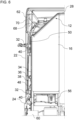
- a special feature of the outer side panel 22 is that different functional components can be concealed behind the outer side panel 22 when the outer side panel 22 is in the closed position and can be accessible from the outside when the outer side panel 22 is open.
- a filler neck 48 can be arranged behind the outer side panel 22.
- the filler neck 48 can be mounted in a (through) opening of the longitudinal side wall 34.
- the filler neck 48 can be closed by means of a detachable cover.
- an adjusting device 50 to be arranged behind the outer side panel 22 and attached to the longitudinal side wall 34.
- at least one other component 52 to be arranged behind the outer side panel 22 and attached, for example, to the longitudinal side wall 34, as shown schematically in Figure 3 is indicated.
- the component 52 can be designed, for example, as a tool (e.g., towing eye, wiper rod, wheel nut wrench, jack), a container, or a storage compartment.
- the motor vehicle 10 may have a windshield cleaning system 54.
- the windshield cleaning system 54 may have at least one cleaning nozzle which is Spraying a cleaning fluid onto a windshield of the motor vehicle and/or a lens of a headlight of the motor vehicle 10.
- the windshield cleaning system 54 further comprises a pump (not shown), a cleaning fluid tank 56, and the filler neck 48.
- the filler neck 48 is connected to the cleaning fluid tank via a line 58, for example a pipe or hose line.
- the pump can suck a cleaning fluid from the cleaning fluid tank 56 and supply it to the at least one cleaning nozzle of the windshield cleaning system 54.
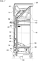
- the cleaning fluid tank 56 can be securely arranged in a previously unused space within the body 12.
- the cleaning fluid tank 56 is arranged at least partially in a section between an inner fender 60 of the motor vehicle 10 and the outer fender 24 of the motor vehicle.
- the cleaning fluid tank 56 is arranged behind the door 20 with respect to the forward direction of travel of the motor vehicle 10, preferably inside the rear wall 16 of the body 12.
- This arrangement of the cleaning fluid tank 56 can provide the further advantage of easy assembly and disassembly (for example, in the event of a repair) of the cleaning fluid tank 56.
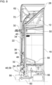
- Figure 8 shows how the cleaning fluid tank 56, preferably together with the filler neck 48 and the line 58, can be guided from below the motor vehicle 10 to the desired mounting position or removed from this (see double arrow in Figure 8 ).
- the cleaning fluid tank 56 is thus accessible and mountable from underneath the motor vehicle 10.
- the arrangement of the cleaning fluid tank 56 also offers the advantage that, in the event of a leak, the cleaning fluid does not flow downwards over sensitive components, but can drip directly onto the ground.
- the motor vehicle 10 may have a height-adjustable roof spoiler 62.
- the Figure 9 shows exemplary height settings of the roof spoiler 62.
- the steepest alignment of the roof spoiler 62 can be used, for example, when mounting or dismounting the roof spoiler on the roof 28.
- the mounting and dismounting (e.g. in case of damage) of the roof spoiler 62 can be carried out in this way without having to dismantle the possibly existing loading structure 14 is required.
- the steepest orientation can, for example, be a vertical or almost vertical orientation of the roof spoiler 62.
- the roof spoiler 62 is arranged on the roof 28.
- the roof spoiler 62 can be pivotably mounted on the roof 28 in the region of its front edge.
- the height of the roof spoiler 62 can be adjusted using the adjustment device 50.
- the adjustment device 50 can have a rail 64.
- the rail 64 is designed as an elongated hole.
- the rail 64 is vertically aligned.
- a longitudinal edge of the elongated hole can have several projections 66 arranged one above the other.
- the projections 66 can enable different possible height adjustments of the roof spoiler 62.
- the projections 66 can be designed, for example, as prongs, claws, or teeth.
- An elongated connecting element 68 (hidden in Figures 7 and 8 ) can be detachably attached, e.g., by means of a screw connection, to a desired projection 66 of the projections 66.
- the connecting element 68 connects the adjusting device 50 to the roof spoiler 62.
- the connecting element 68 can be pivotally attached to an inner side of the roof spoiler 62.
- the connecting element 68 is preferably designed as a rod, tube, or beam.
- the motor vehicle 10 can also have a trim part 70.
- the trim part 70 can be arranged between the roof spoiler 62 and the outer side panel 22 and, for example, bridge a gap between a lower edge of the roof spoiler 62 and the roof 28. The gap can be present depending on a height adjustment of the roof spoiler 62.
- the connecting element 68 can be arranged behind the trim part 70.
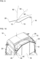
- the Figures 9 and 10 show the roof 28 of the motor vehicle 10.
- the roof 28 has a roof trench or recess 72.
- the recess 72 can extend across the entire width of the roof spoiler 62 or the roof 28.
- the recess 72 serves to partially accommodate the roof spoiler 62 and can also enable its pivoting for height adjustment.
- a front edge of the roof spoiler 62 dips ever deeper into the recess 72 as the roof spoiler 62 is increasingly tilted. This allows for a uniform and uninterrupted airflow to the roof spoiler 62 during operation.
- the recess 72 can have a curved or bent bottom surface that slopes downwards, at least in sections, toward both longitudinal outer sides of the motor vehicle 10, i.e., is directed diagonally downwards. This prevents water from accumulating on the roof 28. Instead, the water can simply flow away toward the longitudinal outer sides.
Landscapes
- Engineering & Computer Science (AREA)
- Mechanical Engineering (AREA)
- Chemical & Material Sciences (AREA)
- Combustion & Propulsion (AREA)
- Transportation (AREA)
- Water Supply & Treatment (AREA)
- Body Structure For Vehicles (AREA)
Claims (14)
- Véhicule automobile (10), de préférence véhicule utilitaire, présentant :une carrosserie (12) ;un panneau latéral extérieur (22), qui est agencé sur un côté extérieur longitudinal du véhicule automobile (10) et qui est relié à la carrosserie (12) de manière mobile,de préférence de manière pivotante, entre une position de fermeture et une position d'ouverture ;un déflecteur de toit (62) ; etun dispositif de réglage (50) au moyen duquel le déflecteur de toit (62) est réglable en hauteur, le dispositif de réglage (50) étant agencé de manière dissimulée derrière le panneau latéral extérieur (22) dans la position de fermeture du panneau latéral extérieur (22) et le dispositif de réglage (50) étant accessible de l'extérieur dans la position d'ouverture du panneau latéral extérieur (22),dans lequel :la carrosserie (12) présente une paroi latérale longitudinale (34) ; etle dispositif de réglage (50) est agencé et/ou fixé sur la paroi latérale longitudinale (34).
- Véhicule automobile (10) selon la revendication 1, dans lequel :le dispositif de réglage (50) présente un rail (64) au moyen duquel le déflecteur de toit (62) est réglable en hauteur,dans lequel de préférence :le rail (64) est réalisé sous la forme d'un trou oblong ; et/oule rail (64) présente plusieurs saillies (66) agencées les unes au-dessus des autres, sur lesquelles le déflecteur de toit (62) peut être disposé de manière indirectement amovible, de préférence au moyen d'une liaison par vis.
- Véhicule automobile (10) selon l'une quelconque des revendications précédentes, présentant en outre :un élément de liaison allongé (68) qui relie le déflecteur de toit (62) au dispositif de réglage (50) de manière réglable en hauteur et qui est de préférence relié au déflecteur de toit (62) de manière pivotante ; etune pièce d'habillage (70) agencée entre le déflecteur de toit (62) et le panneau latéral extérieur (22),l'élément de liaison allongé (68) étant dissimulé au moins par sections derrière la pièce d'habillage (70).
- Véhicule automobile (10) selon l'une quelconque des revendications précédentes, dans lequel :
la carrosserie (12) présente un toit (28) avec un renfoncement (72) et un bord avant du déflecteur de toit (62) s'enfonce dans le renfoncement (72) lors d'un réglage supérieur du déflecteur de toit (62) ; et/ou le déflecteur de toit (62) peut être réglé dans une orientation essentiellement verticale pour le montage ou le démontage au moyen du dispositif de réglage (50). - Véhicule automobile (10) selon la revendication 4, dans lequel :le renfoncement (72) s'étend sur toute une largeur du toit (28) ; etune surface de fond du renfoncement (72) est courbée, incurvée et/ou inclinée vers les deux côtés extérieurs longitudinaux du véhicule automobile (10).
- Véhicule automobile (10) selon l'une quelconque des revendications précédentes, présentant en outre :
une installation de nettoyage de vitres (54) avec un réservoir de liquide de nettoyage (56) et une tubulure de remplissage (48) pour remplir le réservoir de liquide de nettoyage (56), la tubulure de remplissage (48) étant agencée de manière dissimulée derrière le panneau latéral extérieur (22) dans la position de fermeture du panneau latéral extérieur (22) et la tubulure de remplissage (48) étant accessible de l'extérieur dans la position d'ouverture du panneau latéral extérieur (22). - Véhicule automobile (10) selon la revendication 6, dans lequel :
la tubulure de remplissage (48) est agencée et/ou fixée sur la paroi latérale longitudinale (34), de préférence dans une ouverture de la paroi latérale longitudinale (34). - Véhicule automobile (10) selon la revendication 6 ou la revendication 7, dans lequel :le réservoir de liquide de nettoyage (56) est accessible et/ou peut être monté depuis le dessous du véhicule automobile (10) ; et/oule réservoir de liquide de nettoyage (56) est au moins partiellement agencé dans une section entre une aile intérieure (60) du véhicule automobile (10) et une aile extérieure (24) du véhicule automobile (10) ; et/ou le réservoir de liquide de nettoyage (56) est agencé derrière une porte (20) du véhicule automobile (10) par rapport à une direction de marche avant du véhicule automobile (10) ; et/oule réservoir de liquide de nettoyage (56) est agencé à l'intérieur sur une paroi arrière (16) de la carrosserie (12).
- Véhicule automobile (10) selon l'une quelconque des revendications précédentes, présentant en outre :au moins un outil (52) qui est dissimulé par le panneau latéral extérieur (22) dans la position de fermeture du panneau latéral extérieur (22) et qui est accessible de l'extérieur dans la position d'ouverture du panneau latéral extérieur (22) ; et/ouau moins un récipient (52) qui, dans la position de fermeture du panneau latéral extérieur (22), est dissimulé par le panneau latéral extérieur (22) et qui,dans la position d'ouverture du panneau latéral extérieur (22), est accessible de l'extérieur ; et/ou au moins un compartiment de rangement (52) qui, dans la position fermée du panneau latéral extérieur (22), est dissimulé par le panneau latéral extérieur (22) et qui,dans la position ouverte du panneau latéral extérieur (22), est accessible de l'extérieur.
- Véhicule automobile (10) selon l'une quelconque des revendications précédentes, dans lequel :
le panneau latéral extérieur (22) peut être déverrouillé et/ou déplacé à partir de la position fermée au moyen d'un câble Bowden (38) accessible à l'intérieur de la carrosserie (12). - Véhicule automobile (10) selon l'une quelconque des revendications précédentes, dans lequel :
la carrosserie (12) est conçue sous la forme d'une carrosserie de cabine d'un camion. - Véhicule automobile (10) selon l'une quelconque des revendications précédentes, dans lequel :le panneau latéral extérieur (22) est conçu sous la forme d'un volet latéral ; et/oule panneau latéral extérieur (22) est agencé, dans une position de fermeture, obliquement à un angle vers l'extérieur par rapport à un axe longitudinal du véhicule automobile (10), de telle sorte que, de préférence, un bord arrière du panneau latéral extérieur (22) est aligné, de préférence essentiellement à fleur, avec une paroi latérale (30) d'une structure de chargement (14), d'une remorque ou d'une semi-remorque du véhicule automobile (10).
- Véhicule automobile (10) selon l'une quelconque des revendications précédentes, dans lequel :le panneau latéral extérieur (22) est agencé au-dessus d'une aile extérieure (24) et/ou d'un essieu avant (26) du véhicule automobile (10) ; et/oule panneau latéral extérieur (22) s'étend entre une aile extérieure (24) du véhicule automobile (10) et un toit (28) du véhicule automobile (10).
- Véhicule automobile (10) selon l'une quelconque des revendications précédentes, dans lequel :le panneau latéral extérieur (22) peut pivoter vers l'arrière par rapport à une direction de marche avant du véhicule automobile (10) depuis la position de fermeture jusqu'à la position d'ouverture ; et/ou le panneau latéral extérieur (22) présente, par rapport à une direction de marche avant du véhicule automobile (10), un bord arrière droit et un bord avant courbé au moins par sections ; et/oule véhicule automobile (10) présente une porte (20) qui est reliée de manière mobile à la carrosserie (12), et le panneau latéral extérieur (22) est agencé derrière la porte (20) par rapport à une direction de marche avant du véhicule automobile (10).
Applications Claiming Priority (2)
| Application Number | Priority Date | Filing Date | Title |
|---|---|---|---|
| DE102019008489.6A DE102019008489A1 (de) | 2019-12-06 | 2019-12-06 | Kraftfahrzeug mit Dachspoiler |
| PCT/EP2020/083039 WO2021110450A1 (fr) | 2019-12-06 | 2020-11-23 | Véhicule automobile à becquet de toit |
Publications (3)
| Publication Number | Publication Date |
|---|---|
| EP4069578A1 EP4069578A1 (fr) | 2022-10-12 |
| EP4069578C0 EP4069578C0 (fr) | 2025-04-16 |
| EP4069578B1 true EP4069578B1 (fr) | 2025-04-16 |
Family
ID=73544195
Family Applications (1)
| Application Number | Title | Priority Date | Filing Date |
|---|---|---|---|
| EP20811606.1A Active EP4069578B1 (fr) | 2019-12-06 | 2020-11-23 | Véhicule automobile à becquet de toit |
Country Status (5)
| Country | Link |
|---|---|
| EP (1) | EP4069578B1 (fr) |
| KR (1) | KR20220108117A (fr) |
| CN (1) | CN114746328A (fr) |
| DE (1) | DE102019008489A1 (fr) |
| WO (1) | WO2021110450A1 (fr) |
Families Citing this family (1)
| Publication number | Priority date | Publication date | Assignee | Title |
|---|---|---|---|---|
| DE102023111074A1 (de) | 2023-04-28 | 2024-10-31 | Quantron Ag | Spoilervorrichtung, Spoileranordnung, Fahrzeug sowie Verwendung |
Family Cites Families (19)
| Publication number | Priority date | Publication date | Assignee | Title |
|---|---|---|---|---|
| GB2069941B (en) * | 1980-02-02 | 1983-11-16 | Motor Panels Coventry Ltd | Vehicle cabs having airflow defelctors on their roofs |
| US4779915A (en) * | 1987-04-27 | 1988-10-25 | Straight Gary D | Air foil system |
| DE3737380A1 (de) * | 1987-11-04 | 1989-05-18 | Iveco Magirus | Seitenblende zwecks verbesserung der luftfuehrung zwischen fahrerhaus und auflieger |
| DE3800742A1 (de) * | 1988-01-13 | 1989-03-23 | Daimler Benz Ag | Fahrerhaus fuer lastkraftwagen |
| US4904015A (en) * | 1988-08-11 | 1990-02-27 | The Goodyear Tire & Rubber Company | Air deflection system |
| DE19825252A1 (de) * | 1998-06-05 | 1999-12-09 | Fritzmeier Composite Gmbh & Co | Windabweiser |
| AT407628B (de) * | 1999-04-08 | 2001-05-25 | Steyr Nutzfahrzeuge | Halterung für einen am fahrerhausdach eines lastkraftwagens angeordneten dachspoiler |
| US6428084B1 (en) * | 2001-04-24 | 2002-08-06 | Richard M. Liss | Fuel-efficient tractor-trailer system |
| FR2875197A1 (fr) * | 2004-09-14 | 2006-03-17 | Renault Sas | Vehicule automobile pourvu d'un dispositif de lave vitre |
| BRPI0520101A2 (pt) * | 2005-02-22 | 2009-04-22 | Volvo Lastvagnar Ab | cabine para um veÍculo de traÇço tracionado a motor |
| AU2007210992A1 (en) * | 2006-01-31 | 2007-08-09 | Alcoa Inc. | Aerodynamic structures for tractor to trailer junction |
| DE102007036335A1 (de) * | 2007-08-02 | 2009-03-05 | Man Nutzfahrzeuge Ag | Dachspoileranordnung für Nutzfahrzeug-Fahrerhäuser |
| SE534328C2 (sv) * | 2009-11-26 | 2011-07-12 | Scania Cv Ab | Anordning för höjdinställning av en luftriktare och luftriktare försedd med sådan anordning. |
| DE102010031956A1 (de) * | 2010-07-22 | 2011-03-31 | Daimler Ag | Dachspoiler für einen Sattelzug |
| CN201914337U (zh) * | 2010-12-01 | 2011-08-03 | 陈言平 | 一种厢式货车导流罩 |
| DE102014113780B4 (de) * | 2014-09-23 | 2022-06-30 | Zf Cv Systems Europe Bv | Heckspoilereinrichtung für ein Fahrzeug |
| DE102014017732A1 (de) * | 2014-11-29 | 2016-06-02 | Man Truck & Bus Ag | Zugmaschine mit zwei seitlichen Windabweisern und dazwischenliegendem Fluidtank |
| KR101714249B1 (ko) * | 2015-10-28 | 2017-03-08 | 현대자동차주식회사 | 루프 스포일러의 높이조절장치 |
| EP3393892B1 (fr) * | 2015-12-21 | 2020-01-29 | Volvo Truck Corporation | Dispositif déflecteur d'air |
-
2019
- 2019-12-06 DE DE102019008489.6A patent/DE102019008489A1/de active Pending
-
2020
- 2020-11-23 CN CN202080083724.0A patent/CN114746328A/zh active Pending
- 2020-11-23 EP EP20811606.1A patent/EP4069578B1/fr active Active
- 2020-11-23 WO PCT/EP2020/083039 patent/WO2021110450A1/fr not_active Ceased
- 2020-11-23 KR KR1020227022041A patent/KR20220108117A/ko not_active Ceased
Also Published As
| Publication number | Publication date |
|---|---|
| EP4069578A1 (fr) | 2022-10-12 |
| WO2021110450A1 (fr) | 2021-06-10 |
| EP4069578C0 (fr) | 2025-04-16 |
| CN114746328A (zh) | 2022-07-12 |
| KR20220108117A (ko) | 2022-08-02 |
| DE102019008489A1 (de) | 2021-06-10 |
Similar Documents
| Publication | Publication Date | Title |
|---|---|---|
| EP2509850A1 (fr) | Système déflecteur d'air | |
| EP3526081A1 (fr) | Essuie-glace et véhicule équipé d'essuie-glace | |
| EP2520465B1 (fr) | Support de charge pour un véhicule automobile | |
| DE102013008593A1 (de) | Frontlenker-Nutzkraftfahrzeug, insbesondere Frontlenker-Lastkraftfahrzeug, mit frontseitig temporär und formvariabel, insbesondere nasenförmig und haubenförmig einstellbaren sowie nachrüstbaren Luftleitflächen | |
| DE202014100738U1 (de) | Rangierantrieb mit Spritzschutz für Anhänder oder dgl. | |
| DE102019008488B4 (de) | Kraftfahrzeug mit Scheibenreinigungsanlage | |
| EP4069578B1 (fr) | Véhicule automobile à becquet de toit | |
| DE102016007704A1 (de) | Windleitelement zur Montage an einer Seitenwandvorrichtung für ein Fahrzeug | |
| DE102010005311A1 (de) | Kameraanordnung zur Überwachung eines Raumes hinter einem Fahrzeugheck | |
| DE9017550U1 (de) | Anfahrschutz für Lastkraftwagen, insbesondere Sattelauflieger von Sattelschleppern | |
| DE10318987B3 (de) | Kameraanordnung zur Überwachung eines Raumes hinter einem Kraftwagenheck | |
| DE202013004691U1 (de) | Frontlenker-Nutzkraftfahrzeug, insbesondere Frontlenker- Lastkraftfahrzeug, mit frontseitig temporär und formvariabel, insbesondere nasenförmig und haubenförmig einstellbaren sowie nachrüstbaren Luftleitflächen | |
| DE102005037176A1 (de) | Vorrichtung zum Unterteilen eines Laderaums eines Fahrzeugs | |
| DE102006020670A1 (de) | Motorrad mit einem ausklappbaren Verkleidungselement | |
| WO2021083706A1 (fr) | Élément de régulation de l'air pour un véhicule automobile | |
| DE102021006770B4 (de) | Nutzfahrzeug mit Ladesteckdose | |
| DE102021006771B4 (de) | Nutzfahrzeug mit Ladesteckdose | |
| DE102021006774B4 (de) | Nutzfahrzeug mit Ladesteckdose | |
| DE102021006776B4 (de) | Nutzfahrzeug mit Ladesteckdose | |
| DE102006037028B4 (de) | Hochdach für Nutzfahrzeug | |
| DE102021006775B4 (de) | Nutzfahrzeug mit Ladesteckdose | |
| DE102021006773B4 (de) | Nutzfahrzeug mit Ladesteckdose | |
| DE102023001359B3 (de) | Kameraanordnung für ein Fahrzeug | |
| EP1575802B1 (fr) | Vehicule utilitaire, notamment camion avec clignotants supplementaires | |
| DE102010046960A1 (de) | Windleiteinrichtung für einen Kraftwagen |
Legal Events
| Date | Code | Title | Description |
|---|---|---|---|
| STAA | Information on the status of an ep patent application or granted ep patent |
Free format text: STATUS: UNKNOWN |
|
| STAA | Information on the status of an ep patent application or granted ep patent |
Free format text: STATUS: THE INTERNATIONAL PUBLICATION HAS BEEN MADE |
|
| PUAI | Public reference made under article 153(3) epc to a published international application that has entered the european phase |
Free format text: ORIGINAL CODE: 0009012 |
|
| STAA | Information on the status of an ep patent application or granted ep patent |
Free format text: STATUS: REQUEST FOR EXAMINATION WAS MADE |
|
| 17P | Request for examination filed |
Effective date: 20220701 |
|
| AK | Designated contracting states |
Kind code of ref document: A1 Designated state(s): AL AT BE BG CH CY CZ DE DK EE ES FI FR GB GR HR HU IE IS IT LI LT LU LV MC MK MT NL NO PL PT RO RS SE SI SK SM TR |
|
| DAV | Request for validation of the european patent (deleted) | ||
| DAX | Request for extension of the european patent (deleted) | ||
| GRAP | Despatch of communication of intention to grant a patent |
Free format text: ORIGINAL CODE: EPIDOSNIGR1 |
|
| STAA | Information on the status of an ep patent application or granted ep patent |
Free format text: STATUS: GRANT OF PATENT IS INTENDED |
|
| INTG | Intention to grant announced |
Effective date: 20241219 |
|
| GRAS | Grant fee paid |
Free format text: ORIGINAL CODE: EPIDOSNIGR3 |
|
| GRAA | (expected) grant |
Free format text: ORIGINAL CODE: 0009210 |
|
| STAA | Information on the status of an ep patent application or granted ep patent |
Free format text: STATUS: THE PATENT HAS BEEN GRANTED |
|
| AK | Designated contracting states |
Kind code of ref document: B1 Designated state(s): AL AT BE BG CH CY CZ DE DK EE ES FI FR GB GR HR HU IE IS IT LI LT LU LV MC MK MT NL NO PL PT RO RS SE SI SK SM TR |
|
| REG | Reference to a national code |
Ref country code: GB Ref legal event code: FG4D Free format text: NOT ENGLISH |
|
| REG | Reference to a national code |
Ref country code: CH Ref legal event code: EP Ref country code: DE Ref legal event code: R096 Ref document number: 502020010860 Country of ref document: DE |
|
| REG | Reference to a national code |
Ref country code: IE Ref legal event code: FG4D Free format text: LANGUAGE OF EP DOCUMENT: GERMAN |
|
| U01 | Request for unitary effect filed |
Effective date: 20250502 |
|
| U07 | Unitary effect registered |
Designated state(s): AT BE BG DE DK EE FI FR IT LT LU LV MT NL PT RO SE SI Effective date: 20250508 |
|
| PG25 | Lapsed in a contracting state [announced via postgrant information from national office to epo] |
Ref country code: ES Free format text: LAPSE BECAUSE OF FAILURE TO SUBMIT A TRANSLATION OF THE DESCRIPTION OR TO PAY THE FEE WITHIN THE PRESCRIBED TIME-LIMIT Effective date: 20250416 |
|
| PG25 | Lapsed in a contracting state [announced via postgrant information from national office to epo] |
Ref country code: NO Free format text: LAPSE BECAUSE OF FAILURE TO SUBMIT A TRANSLATION OF THE DESCRIPTION OR TO PAY THE FEE WITHIN THE PRESCRIBED TIME-LIMIT Effective date: 20250716 Ref country code: GR Free format text: LAPSE BECAUSE OF FAILURE TO SUBMIT A TRANSLATION OF THE DESCRIPTION OR TO PAY THE FEE WITHIN THE PRESCRIBED TIME-LIMIT Effective date: 20250717 |
|
| PG25 | Lapsed in a contracting state [announced via postgrant information from national office to epo] |
Ref country code: PL Free format text: LAPSE BECAUSE OF FAILURE TO SUBMIT A TRANSLATION OF THE DESCRIPTION OR TO PAY THE FEE WITHIN THE PRESCRIBED TIME-LIMIT Effective date: 20250416 |
|
| PG25 | Lapsed in a contracting state [announced via postgrant information from national office to epo] |
Ref country code: HR Free format text: LAPSE BECAUSE OF FAILURE TO SUBMIT A TRANSLATION OF THE DESCRIPTION OR TO PAY THE FEE WITHIN THE PRESCRIBED TIME-LIMIT Effective date: 20250416 |
|
| PG25 | Lapsed in a contracting state [announced via postgrant information from national office to epo] |
Ref country code: RS Free format text: LAPSE BECAUSE OF FAILURE TO SUBMIT A TRANSLATION OF THE DESCRIPTION OR TO PAY THE FEE WITHIN THE PRESCRIBED TIME-LIMIT Effective date: 20250716 |
|
| PG25 | Lapsed in a contracting state [announced via postgrant information from national office to epo] |
Ref country code: IS Free format text: LAPSE BECAUSE OF FAILURE TO SUBMIT A TRANSLATION OF THE DESCRIPTION OR TO PAY THE FEE WITHIN THE PRESCRIBED TIME-LIMIT Effective date: 20250816 |
|
| U20 | Renewal fee for the european patent with unitary effect paid |
Year of fee payment: 6 Effective date: 20251126 |
|
| PG25 | Lapsed in a contracting state [announced via postgrant information from national office to epo] |
Ref country code: SM Free format text: LAPSE BECAUSE OF FAILURE TO SUBMIT A TRANSLATION OF THE DESCRIPTION OR TO PAY THE FEE WITHIN THE PRESCRIBED TIME-LIMIT Effective date: 20250416 |
|
| PG25 | Lapsed in a contracting state [announced via postgrant information from national office to epo] |
Ref country code: CZ Free format text: LAPSE BECAUSE OF FAILURE TO SUBMIT A TRANSLATION OF THE DESCRIPTION OR TO PAY THE FEE WITHIN THE PRESCRIBED TIME-LIMIT Effective date: 20250416 |
|
| PG25 | Lapsed in a contracting state [announced via postgrant information from national office to epo] |
Ref country code: SK Free format text: LAPSE BECAUSE OF FAILURE TO SUBMIT A TRANSLATION OF THE DESCRIPTION OR TO PAY THE FEE WITHIN THE PRESCRIBED TIME-LIMIT Effective date: 20250416 |
|
| PLBE | No opposition filed within time limit |
Free format text: ORIGINAL CODE: 0009261 |
|
| STAA | Information on the status of an ep patent application or granted ep patent |
Free format text: STATUS: NO OPPOSITION FILED WITHIN TIME LIMIT |
|
| REG | Reference to a national code |
Ref country code: CH Ref legal event code: L10 Free format text: ST27 STATUS EVENT CODE: U-0-0-L10-L00 (AS PROVIDED BY THE NATIONAL OFFICE) Effective date: 20260225 |
|
| 26N | No opposition filed |
Effective date: 20260119 |