EP2910457A1 - Entraînement de man'uvre doté de barre de protection pour remorque ou similaire - Google Patents
Entraînement de man'uvre doté de barre de protection pour remorque ou similaire Download PDFInfo
- Publication number
- EP2910457A1 EP2910457A1 EP15155577.8A EP15155577A EP2910457A1 EP 2910457 A1 EP2910457 A1 EP 2910457A1 EP 15155577 A EP15155577 A EP 15155577A EP 2910457 A1 EP2910457 A1 EP 2910457A1
- Authority
- EP
- European Patent Office
- Prior art keywords
- splash guard
- rangierantrieb
- drive roller
- trailer
- wheel
- Prior art date
- Legal status (The legal status is an assumption and is not a legal conclusion. Google has not performed a legal analysis and makes no representation as to the accuracy of the status listed.)
- Withdrawn
Links
Images


Classifications
-
- B—PERFORMING OPERATIONS; TRANSPORTING
- B62—LAND VEHICLES FOR TRAVELLING OTHERWISE THAN ON RAILS
- B62D—MOTOR VEHICLES; TRAILERS
- B62D59/00—Trailers with driven ground wheels or the like
- B62D59/04—Trailers with driven ground wheels or the like driven from propulsion unit on trailer
Definitions
- the invention relates to a shunting drive for a trailer or the like., With a drive motor and a drive roller for a wheel of the trailer.
- the invention also relates to a trailer with a shunting drive.
- a splash guard is arranged. This is usually designed as a rubber or plastic flap and is intended to prevent water, dirt or even stones being thrown from the tire to a vehicle driving behind the truck.
- the object of the invention is to protect a behind the trailer moving vehicle from water, dirt or even stones that are whirled up by the wheels of the trailer.
- a splash guard according to the invention is provided in a shunting drive of the type mentioned, which is integrated with the Rangierantrieb to form an assembly.
- the invention is based on the recognition that, in order to be effective, such a splash guard should be arranged as close as possible behind the (rear) wheel of the trailer, ie in a region in which the maneuvering drive is located, if the trailer with such Is provided.
- the splash guard is integrated with the Rangierantrieb to an assembly in that it is either located in the immediate vicinity of the Rangierantriebs or mounted on Rangierantrieb itself.
- the splash guard between a starting position and a Rangier ein is movable.
- the splash guard ensures optimum protection for all vehicles that drive behind the trailer.
- the Rangier ein allows The splash guard that the drive roller of Rangierantriebs unhindered attack on the wheel of the trailer and can turn this.
- a hook is provided, with which the tip protection is fixable in the Rangier ein.
- This is a technically particularly easy to implement solution in which the splash guard and the lower portion of the splash guard is moved upwards and hooked so that the drive roller can be freely engaged with the wheel of the trailer.
- the splash guard is detachably attached. This embodiment is based on the idea that the splash guard in normal operation, so when the trailer is pulled, is mounted in a suitable position on the trailer or on Rangierantrieb. However, if the trailer is to be moved by means of the Rangierantriebs, the splash guard is loosened and removed, so that the drive roller can freely attack on the wheel of the trailer.
- a clip connection is provided, by means of which the splash guard can be clipped.
- a holder is provided, in which the splash guard is inserted laterally.
- a small amount of technical effort is required to attach the splash guard on the trailer or the Rangierantrieb. It is also particularly advantageous that the splash guard can be attached or detached without tools.
- the splash guard is part of the Rangierantriebs. In this case, it is no longer necessary to remove the splash guard when the trailer is to be moved by means of Rangierantriebs. Instead, the splash guard is designed so that it does not hinder the process of the trailer by means of the Rangierantriebs.
- the splash guard is designed as part of a housing of the Rangierantriebs.
- the splash guard can therefore be designed as an extension or projection of the housing and provide in this way the desired function.
- the splash guard may alternatively be mounted on the Rangierantrieb, for example by a screw or the like. This allows to replace the splash guard when needed.
- the Rangierantrieb is provided with a pressure mechanism with which he and thus the drive roller can be adjusted from a starting position to a Rangiergna, and that the splash guard is arranged on Rangierantrieb that he is in the Rangiergna is located when the maneuvering drive is in the maneuvering position.
- This embodiment is based on the basic idea that an adjusting movement, which performs the Rangierantrieb to press the drive roller against the wheel of the trailer, is also used to adjust the splash guard from the starting position to the Rangier ein.
- the Rangierantrieb is provided with a pressure mechanism with which the drive roller can be adjusted from a starting position to a Rangiergna, and that the splash guard is coupled to the pressure mechanism so that it is automatically brought from the starting position in the Rangier ein is when the drive roller is brought from the initial position in the Rangiergna.
- This embodiment is based on the idea to actively adjust the splash guard then, when the drive roller is brought into engagement with the wheel of the trailer. This active adjustment can be done either by the fact that the splash guard is coupled in any way with the pressure mechanism and is thereby adjusted when this adjusts the drive roller, or that a separate drive is provided for the splash guard, which is then actuated, although the pressure mechanism is pressed.
- the splash guard when the pressure mechanism is actuated, the splash guard may be displaced laterally out of the area between the drive roller and the wheel, generally in a direction parallel to the axis of rotation of the trailer wheel.
- the splash guard is adjusted in the vertical direction from the area between the drive roller and the wheel.
- the splash guard is made in two parts so that the two parts can be pulled apart, so that between them a space for the drive roller is formed. At this Design is thus opened between the two parts of the splash guard a kind of window through which the drive roller can engage the wheel of the trailer.
- the drive roller is provided with a cladding which covers it at least on the wheel-facing side, and that the splash guard is provided on the cladding.
- the drive roller and thus also the Rangierantrieb be protected from contamination when the drive roller is in the starting position.
- the lining consists of at least two parts, which is adjustable relative to each other between a starting position in which the drive roller is at least on the side facing the wheel, and a Rangier ein adjustable, in which the drive roller the wheel can be engaged.
- a panel can be opened with little effort in a space-saving manner.
- the two parts are designed as shells which can be moved into one another. In this case, no additional radial clearance is required when the panel needs to be opened; the two shells can be rotated concentrically relative to each other.
- the splash guard is provided with an opening for the drive roller.
- the splash guard is designed in the manner of a roller blind, that is, for example, in the vertical direction from a pulled-down starting position in a rolled Rangier ein is adjustable.
- the splash guard is designed as a tear-off section of a roller blind. This allows a currently used one Section of the roller blind, so the acting as a splash guard section, then tear off and thereby remove when the drive roller to attack on the wheel of the trailer.
- the currently serving as a splash guard portion of the roller blind can be either demolished by hand or by the fact that it is first clamped between the wheel of the trailer and the drive roller of the Rangierantriebs and then demolished.
- a "new" section of the roller blind is pulled down, so that there is again a splash guard.
- the roller blind is automatically adjusted by a drive by a predetermined distance down.
- the splash guard is provided with a reflector. This increases traffic safety.
- the splash guard may also be associated with a sensor. In this way additional functions can be implemented.
- the senor may be a roll sensor of its. This makes it possible to detect from the movements of the splash guard a possible rolling of the trailer.
- the sensor may also be a road condition sensor.
- the information of the road condition sensor can then be provided to a controller that controls, for example, the suspension of the trailer or a roll damper.
- the senor is a tilt sensor.
- the tilt sensor signals can be provided to an operator either in the trailer or on a control for the shunting drive to make it easier for the operator to orient the trailer exactly horizontally.
- a Radverhüllung is integrated. This is particularly advantageous for so-called permanent campers.
- the splash guard has a surface with nano-effect. This reduces the tendency to fouling.
- the splash guard is designed as Cognitivefahrkeil. This allows the splash guard to be used for horizontal alignment of the trailer when it is detached during maneuvering of the trailer.
- the splash guard is designed as a cleaning element for the drive roller.
- the drive roller can be cleaned when it is either dirty after a long drive of the trailer or after the trailer was moved by means of the Rangierantriebs on a dirty surface.
- the splash guard is designed as a closure element for a bottom opening of the trailer.
- the then not required outlets of an air conditioner can be closed.
- cold bridges can be reduced.
- a trailer with a splash guard which can be adjusted between a starting position and a Rangier too, the splash guard is brought from the Rangier too in the starting position when the trailer is moved in the train operation. This can be done for example by an automatic control that detects that the trailer is coupled to a tractor or pulled by this.
- the splash guard is automatically adjusted to the starting position as soon as a predefined speed threshold is exceeded.
- a predefined speed threshold is exceeded.
- the splash guard is passively adjusted to the starting position. This can be done in particular by the wind or the rotation of the tire. It is also conceivable that the splash guard is then adjusted to the starting position when rain and / or dirt is detected.
- a trailer having a shunting drive, a wheel that can be driven by the shunting drive, a wheel well in which the wheel is disposed, and a splash guard integrated with the wheel well.
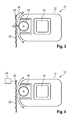
- FIG. 1 schematically a Rangierantrieb 10 is shown, which has a housing 12 and a drive roller 14. Inside the housing 12, an electric motor is arranged in a motor housing 16, which is connected via a gear to the drive roller 14. For power supply, a battery (not shown) is provided.
- the Rangierantrieb serves to a trailer, especially a caravan or the like, then electrically operated to adjust when the trailer is not coupled to the tractor.
- the shunting drive can be used in particular to maneuver it in a campsite and to move into the final position.
- the Rangierantrieb 10 is when it is not needed (ie in particular when the trailer is coupled to a tractor), in a starting position in which the drive roller 14 at a distance from a in FIG. 1 schematically shown wheel 18 of the trailer is located.
- the Rangierantrieb is off the in FIG. 1 shown initial position brought into a Rangier ein in which the drive roller 14 engages the wheel 18 of the trailer.
- a pressure mechanism is provided with which the Rangierantrieb either translationally or rotationally can be adjusted so that the drive roller 14 is applied to the running surface of the wheel 18.
- a splash guard 20 is provided which is intended to prevent water, dirt or pebbles, which are whirled up by the wheel 18 of the trailer while driving, being thrown in the direction of a vehicle following behind.
- the splash guard 20 is thus seen in the direction of travel of the trailer just behind the wheel 18 of the trailer attached.
- a uniaxial trailer will have a splash guard on each side of the trailer.
- either a single splash guard may be mounted behind the rearmost wheel, or each of the wheels of each vehicle side may be associated with a splash guard.
- a rubber or plastic mat can be used, as they are basically known for the same purpose in trucks.
- the splash guard 20 is attached to a suspension 22. This can be assigned to the wheelhouse of the trailer, the frame of the trailer or the Rangierantrieb 10.
- the splash guard 20 this is located immediately behind the wheel 18 and thus between the running surface of the wheel 18 and the drive roller 14 when the Rangierantrieb 10 is in the starting position.
- the splash guard 20 In order to operate the shunting drive, the splash guard 20 must be removed from the area between the running surface of the wheel 18 and the drive roller 14.
- the suspension 22 is designed to be movable, so that the splash guard 20 from the initial position in which it is located between the wheel 18 and the drive roller 14, can be adjusted to a Rangier ein in which the drive roller 14 unhindered by the splash guard with the Tread of the wheel 18 can be engaged.
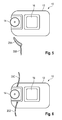
- a hook 24 is provided, to which the lower end of the splash guard 20 can be attached when it is in the Rangier too.
- the splash guard 20 is not moved substantially in the vertical direction, but pulled laterally in the direction of the arrow P from the space between the running surface of the wheel 18 and the drive roller 14.
- a rail can be used, for example, an aluminum profile, in which the thickened upper edge of the splash guard is inserted laterally. This edge can for example be provided with a piping.
- a locking mechanism may be provided, such as a strap or snap spring or a snap hook with which the splash guard 20 can be locked in the rail and can be easily solved by hand.
- sensors may be provided which detect in which position the splash guard is currently located. If an operator wants to move the maneuvering drive from the initial position to the maneuvering position while the splash guard 20 is still in the starting position, a warning signal can be output.
- the splash guard 20 and in particular its suspension 22 is coupled to the Rangierantrieb 10 and its pressure mechanism that it is automatically adjusted from the starting position to the Rangier ein (symbolized by the two parts A) when the drive roller 14 from the starting position is moved to the Rangier ein (symbolized by the arrow P).
- a schematically indicated coupling mechanism 26 may be used, for example, a linkage connection or an adjusting device with servomotor.
- the splash guard 20 can be adjusted by a separate adjustment 28 from the initial position in the Rangier ein. This is triggered separately, for example, by an operator before the shunting drive is activated.
- a warning function can be implemented, which prevents the Rangierantrieb 10 is moved from the starting position to the Rangiergna when the splash guard 20 is still in its initial position.
- the splash guard is made in two parts, namely in the form of a rigid spoiler element 20A, which connects directly to the housing 12 of the Rangierantriebs 10, and to the flexible splash guard element 20B, which is attached to the spoiler element 20A.
- the advantage of this embodiment is that the spoiler does not have to be moved out of the space between the drive roller 14 and the wheel 18 of the trailer before the shunting drive 10 is activated.
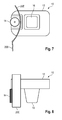
- a two-part splash guard is used. This consists here of an upper part 20 C, which is arranged above the drive roller 14, and a lower part 20 D, which is mounted below the drive roller 14. In this way, the entire area behind the wheel 18 is covered, first by the upper part 20C, then by the drive roller 14 and then by the lower part 20D.
- the parts 20C, 20D may be made of different materials.
- a material with less flexibility may be used, for example plastic, while for the lower part 20D rubber or a similarly flexible and impact-damping material is used.
- the two parts 20C, 20D of the spoiler can be exchangeably mounted on the shunting drive 10, for example by a clip connection.
- a splash guard which is composed of a rigid splash guard 20E and a flexible splash guard element 20B.
- the splash guard 20E is designed in the manner of a mudguard or fender and extends around the drive roller 14 around on its side facing away from the wheel 18 side. Also in this embodiment, there is the advantage that the splash guard does not have to be removed or adjusted when the Rangierantrieb 10 is to be activated.
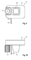
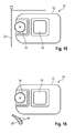
- FIGS. 9 and 10 an embodiment is shown in which a single splash guard 20 is used, which is mounted below the Rangierantriebs 10 here.
- the splash guard 20 is here attached to the underside of the housing 12 of the Rangierantriebs 10, for example by means of a suspension 22 which is fixedly mounted there and in the lateral direction so far beyond the housing 12 (see FIG. 10 ) that the splash guard 20 laterally protrudes slightly beyond the drive roller 14.
- the splash guard 20 of two sub-elements 20F, 20G is formed, both of which consist of a material with a certain inherent rigidity.
- the lower part 20G may have a lower rigidity towards its lower end or, if it is made, for example, as a two-component part, may be made of a different material, for example rubber.
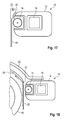
- the two parts 20F, 20G in the in FIG. 11 Dashed position shown adjusted, so substantially exploded, so that the drive roller 14 centrally between them pass and can engage with the running surface of the wheel 18 in engagement.
- a slotted guide can be used to adjust the two parts 20F, 20G of the splash guard 20. Either a separate drive for the two parts 20F, 20G is provided. Alternatively, it is also possible, via a slotted guide or a lever mechanism, the movement of the Rangierantriebs 10, which performs this, in order to move from the starting position in the Rangier ein to implement in the opening movement of the two parts 20F, 20G.
- the particular advantage of this embodiment is that a pinch protection is realized, since the drive roller is made available shortly before the time at which it engages the wheel 18.
- the splash guard is provided with a predefined opening, for example by means of a perforation, so that an operator when he activates the Rangierantrieb 10, the corresponding part breaks out of the splash guard, thus creating the opening through which the Drive roller 14 of the Rangierantriebs 10 can engage the tread of the wheel 18.
- the splash guard 20 may in particular be designed to be easily interchangeable, for example as a disposable splash tab, which is replaced by a new one each time the opening has been broken out of the splashguard.
- FIG. 15 an embodiment is shown in which the splash guard is adjusted from the initial position shown in solid lines in the Rangier ein dashed lines characterized in that it is folded up and stored, for example, on the Rangierantrieb 10.
- the splash guard 20 can be folded down again.
- FIG. 16 an embodiment is shown in which the splash guard 20 similar to that in in FIG. 5 embodiment shown having a spoiler.
- This is provided here with schematically indicated sensors 40, with which various additional functions can be realized, for example, detection of the road condition, a rattle detection or the like.
- FIG. 17 an embodiment is shown in which the splash guard 20 is mounted in a suspension 22 similar to earlier embodiments.
- Essential feature of the embodiment according to FIG. 17 is that in the wedge an additional function is integrated.
- the upper end of the splash guard 20 is made thickened, so that a two-stage Auffahrkeil 42 is realized.
- the splash guard can be removed from the suspension 22 and then used to align the trailer horizontally.
- the splash guard 20 may also be configured to be used for covering or closing floor openings, such as the floor panels of an air conditioner. In this way, for example, during winter camping, the heat loss to the environment can be reduced. In the same way as when using the splash guard as Auffahrkeil this is a certain minimum stiffness makes sense.
- FIG. 18 an embodiment is shown in which the splash guard 20 is integrated into the wheel arch 50 of the trailer.
- the suspension 22 is mounted on a bracket 52, which can be adjusted either manually or automatically, to bring the splash guard 20 from the starting position in the Rangier ein.
- a separate drive for example by means of a servo motor, can be used, or the shunting drive 10 can be coupled to the holder 52 via a linkage, a drive cable, etc. such that the holder 52 is appropriately adjusted when the shunting drive 10 is moved from the starting position to the Rangier ein.
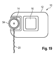
- FIG. 19 an embodiment is shown in which the upper end of the splash guard 20 is provided with a sleeve-shaped Aufsteckabêt 54 which can be pushed onto the drive roller 14 in the axial direction.
- the slip-on portion 54 is flexible and designed with a small undersize relative to the drive roller 14, so that the splash guard 20 is reliably fixed on the drive roller during the drive of the trailer.
- the splash guard 20 is used in this embodiment as a contamination protection for the drive roller 14th
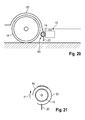
- FIGS. 20 and 21 an embodiment is shown in which the splash guard 20 is attached to a panel 60 which surrounds the drive roller 14.
- the panel 60 (see in particular FIG. 21 ) consists of two shell-like parts 62, 64, of which the part 62 is fixed and surrounds the drive roller 14 by a little more than 180 °.
- the second part 64 is designed to be movable relative to the first part 62 and extends over an angular range such that the drive roller 14, when the part 64 is in the starting position, is completely enclosed together with the fixed part 62.
- the drive roller 14 can be brought into engagement with the running surface of the wheel 18, the second part 64 of the cover 60 can be pivoted relative to the fixed part 62 (see the arrow P in FIG FIG. 21 ), so that the panel is open on the wheel 18 side facing.
- the second part 64 can in particular be pivoted concentrically with the drive roller 14.
- the fixed part 62 is carried out concentrically with the drive roller 14, the overall result is a very compact assembly.
Applications Claiming Priority (1)
| Application Number | Priority Date | Filing Date | Title |
|---|---|---|---|
| DE201420100738 DE202014100738U1 (de) | 2014-02-19 | 2014-02-19 | Rangierantrieb mit Spritzschutz für Anhänder oder dgl. |
Publications (1)
| Publication Number | Publication Date |
|---|---|
| EP2910457A1 true EP2910457A1 (fr) | 2015-08-26 |
Family
ID=50480221
Family Applications (1)
| Application Number | Title | Priority Date | Filing Date |
|---|---|---|---|
| EP15155577.8A Withdrawn EP2910457A1 (fr) | 2014-02-19 | 2015-02-18 | Entraînement de man'uvre doté de barre de protection pour remorque ou similaire |
Country Status (2)
| Country | Link |
|---|---|
| EP (1) | EP2910457A1 (fr) |
| DE (1) | DE202014100738U1 (fr) |
Cited By (3)
| Publication number | Priority date | Publication date | Assignee | Title |
|---|---|---|---|---|
| USD905217S1 (en) | 2018-09-05 | 2020-12-15 | Dometic Sweden Ab | Air conditioning apparatus |
| USD907183S1 (en) | 2016-11-23 | 2021-01-05 | Dometic Sweden Ab | Air conditioning apparatus |
| US11772452B2 (en) | 2017-11-16 | 2023-10-03 | Dometic Sweden Ab | Air conditioning apparatus for recreational vehicles |
Families Citing this family (3)
| Publication number | Priority date | Publication date | Assignee | Title |
|---|---|---|---|---|
| DE202014101524U1 (de) * | 2014-03-31 | 2015-04-02 | Reich Kg, Regel- Und Sicherheitstechnik | Hilfsantrieb für einen Anhänger und Anhänger |
| DE202014101955U1 (de) * | 2014-04-25 | 2015-07-16 | Alois Kober Gmbh | Spritzschutz für Fahrzeuganhänger mit Rangierhilfe |
| DE202018101924U1 (de) * | 2018-04-10 | 2019-04-11 | Reich Gmbh Regel- Und Sicherheitstechnik | Hilfsantrieb für ein Fahrzeug, insbesondere für einen Anhänger, sowie Anhänger |
Citations (6)
| Publication number | Priority date | Publication date | Assignee | Title |
|---|---|---|---|---|
| EP1447312A1 (fr) * | 2003-02-13 | 2004-08-18 | Reich KG | Dispositif de manoeuvre pour véhicules non motorisés |
| EP1714858A1 (fr) * | 2005-04-18 | 2006-10-25 | Truma Gerätetechnik GmbH & Co. KG | Entraînement auxiliaire pour remorque avec rouleau d'entraînement supporté d'un seul côté |
| EP1764274A1 (fr) * | 2005-09-16 | 2007-03-21 | Purple Line Limited | Dispositif pour déplacer des remorques |
| EP2028085A1 (fr) * | 2007-08-23 | 2009-02-25 | Reich GmbH | Boîte auxiliaire de vitesse pour une caravane |
| GB2457725A (en) * | 2008-02-25 | 2009-08-26 | James Richard Yates | Machines for manoeuvring trailers |
| EP2669157A2 (fr) * | 2012-05-29 | 2013-12-04 | Truma Gerätetechnik GmbH & Co. KG | Entraînement de rangement pour remorque |
-
2014
- 2014-02-19 DE DE201420100738 patent/DE202014100738U1/de not_active Expired - Lifetime
-
2015
- 2015-02-18 EP EP15155577.8A patent/EP2910457A1/fr not_active Withdrawn
Patent Citations (6)
| Publication number | Priority date | Publication date | Assignee | Title |
|---|---|---|---|---|
| EP1447312A1 (fr) * | 2003-02-13 | 2004-08-18 | Reich KG | Dispositif de manoeuvre pour véhicules non motorisés |
| EP1714858A1 (fr) * | 2005-04-18 | 2006-10-25 | Truma Gerätetechnik GmbH & Co. KG | Entraînement auxiliaire pour remorque avec rouleau d'entraînement supporté d'un seul côté |
| EP1764274A1 (fr) * | 2005-09-16 | 2007-03-21 | Purple Line Limited | Dispositif pour déplacer des remorques |
| EP2028085A1 (fr) * | 2007-08-23 | 2009-02-25 | Reich GmbH | Boîte auxiliaire de vitesse pour une caravane |
| GB2457725A (en) * | 2008-02-25 | 2009-08-26 | James Richard Yates | Machines for manoeuvring trailers |
| EP2669157A2 (fr) * | 2012-05-29 | 2013-12-04 | Truma Gerätetechnik GmbH & Co. KG | Entraînement de rangement pour remorque |
Cited By (4)
| Publication number | Priority date | Publication date | Assignee | Title |
|---|---|---|---|---|
| USD907183S1 (en) | 2016-11-23 | 2021-01-05 | Dometic Sweden Ab | Air conditioning apparatus |
| US11772452B2 (en) | 2017-11-16 | 2023-10-03 | Dometic Sweden Ab | Air conditioning apparatus for recreational vehicles |
| USD905217S1 (en) | 2018-09-05 | 2020-12-15 | Dometic Sweden Ab | Air conditioning apparatus |
| USD944374S1 (en) | 2018-09-05 | 2022-02-22 | Dometic Sweden Ab | Air conditioning apparatus |
Also Published As
| Publication number | Publication date |
|---|---|
| DE202014100738U1 (de) | 2014-03-20 |
Similar Documents
| Publication | Publication Date | Title |
|---|---|---|
| DE102004041709C5 (de) | Fahrzeug mit automatisch öffnender Klappe | |
| EP2910457A1 (fr) | Entraînement de man'uvre doté de barre de protection pour remorque ou similaire | |
| EP2454435B1 (fr) | Unité modulaire avec dispositif détecteur | |
| DE102004049054A1 (de) | Unfallwarnvorrichtung für ein Fahrzeug | |
| DE202005006903U1 (de) | Kollisionsschutzvorrichtung für einen Außenspiegel | |
| DE102005048142A1 (de) | Zugfahrzeug für Zugfahrzeug-Anhängerkombinationen mit geschwindigkeitsabhängig verstellbarer Windleiteinrichtung | |
| DE102007043477B4 (de) | Kraftfahrzeug mit einer fremdkraftbetriebenen Heckklappe | |
| DE102005022421A1 (de) | Kollisionsvermeidungssystem und Verfahren zum Betreiben eines Kollisionsvermeidungssystems | |
| DE19901016B4 (de) | Nutzfahrzeug | |
| DE10304707B3 (de) | Fahrzeug mit Außenschwingtür | |
| DE19546559C1 (de) | Abdeckung für eine Griffmulde eines Türgriffs von Fahrzeugen | |
| DE102005000944A1 (de) | Lastkraftwagen | |
| DE4134501A1 (de) | Lastwagen, insbesondere sattelauflieger | |
| DE202010008150U1 (de) | Vorrichtung zum Anklappen eines Außenspiegels bei Kraftfahrzeugen | |
| DE4331613C2 (de) | Kurzkupplungssystem | |
| EP3287347B1 (fr) | Entraînement d'assistance pour une remorque et remorque | |
| EP0361166A1 (fr) | Dispositif de réglage des deux rétroviseurs extérieurs du véhicule tracteur d'un camion semi-remorque | |
| EP2952421B1 (fr) | Entraînement d'assistance pour une remorque et remorque | |
| DE3401521A1 (de) | Kotfluegel fuer fahrzeuge, insbesondere fuer die hinterraeder von sattelzugmaschinen | |
| DE19936578A1 (de) | Rückspiegel mit automatischer Einstellung für Kraftfahrzeuge mit Anhänger | |
| DE102019007568A1 (de) | Luftleitelement für ein Kraftfahrzeug | |
| DE102004037959A1 (de) | System zur automatischen Außenspiegelverstellung | |
| DE102012013848A1 (de) | Vorderkotflügel und Kraftfahrzeug | |
| DE102007052617A1 (de) | Kraftfahrzeug mit einer Kamera | |
| EP3093223B1 (fr) | Attelage de vehicule comprenant un vehicule de traction et un vehicule remorque, en particulier semi-remorque |
Legal Events
| Date | Code | Title | Description |
|---|---|---|---|
| PUAI | Public reference made under article 153(3) epc to a published international application that has entered the european phase |
Free format text: ORIGINAL CODE: 0009012 |
|
| AK | Designated contracting states |
Kind code of ref document: A1 Designated state(s): AL AT BE BG CH CY CZ DE DK EE ES FI FR GB GR HR HU IE IS IT LI LT LU LV MC MK MT NL NO PL PT RO RS SE SI SK SM TR |
|
| AX | Request for extension of the european patent |
Extension state: BA ME |
|
| STAA | Information on the status of an ep patent application or granted ep patent |
Free format text: STATUS: THE APPLICATION IS DEEMED TO BE WITHDRAWN |
|
| 18D | Application deemed to be withdrawn |
Effective date: 20160227 |