EP2910457A1 - Manoeuvring drive with splash guard for trailers and the like. - Google Patents
Manoeuvring drive with splash guard for trailers and the like. Download PDFInfo
- Publication number
- EP2910457A1 EP2910457A1 EP15155577.8A EP15155577A EP2910457A1 EP 2910457 A1 EP2910457 A1 EP 2910457A1 EP 15155577 A EP15155577 A EP 15155577A EP 2910457 A1 EP2910457 A1 EP 2910457A1
- Authority
- EP
- European Patent Office
- Prior art keywords
- splash guard
- rangierantrieb
- drive roller
- trailer
- wheel
- Prior art date
- Legal status (The legal status is an assumption and is not a legal conclusion. Google has not performed a legal analysis and makes no representation as to the accuracy of the status listed.)
- Withdrawn
Links
Images


Classifications
-
- B—PERFORMING OPERATIONS; TRANSPORTING
- B62—LAND VEHICLES FOR TRAVELLING OTHERWISE THAN ON RAILS
- B62D—MOTOR VEHICLES; TRAILERS
- B62D59/00—Trailers with driven ground wheels or the like
- B62D59/04—Trailers with driven ground wheels or the like driven from propulsion unit on trailer
Definitions
- the invention relates to a shunting drive for a trailer or the like., With a drive motor and a drive roller for a wheel of the trailer.
- the invention also relates to a trailer with a shunting drive.
- a splash guard is arranged. This is usually designed as a rubber or plastic flap and is intended to prevent water, dirt or even stones being thrown from the tire to a vehicle driving behind the truck.
- the object of the invention is to protect a behind the trailer moving vehicle from water, dirt or even stones that are whirled up by the wheels of the trailer.
- a splash guard according to the invention is provided in a shunting drive of the type mentioned, which is integrated with the Rangierantrieb to form an assembly.
- the invention is based on the recognition that, in order to be effective, such a splash guard should be arranged as close as possible behind the (rear) wheel of the trailer, ie in a region in which the maneuvering drive is located, if the trailer with such Is provided.
- the splash guard is integrated with the Rangierantrieb to an assembly in that it is either located in the immediate vicinity of the Rangierantriebs or mounted on Rangierantrieb itself.
- the splash guard between a starting position and a Rangier ein is movable.
- the splash guard ensures optimum protection for all vehicles that drive behind the trailer.
- the Rangier ein allows The splash guard that the drive roller of Rangierantriebs unhindered attack on the wheel of the trailer and can turn this.
- a hook is provided, with which the tip protection is fixable in the Rangier ein.
- This is a technically particularly easy to implement solution in which the splash guard and the lower portion of the splash guard is moved upwards and hooked so that the drive roller can be freely engaged with the wheel of the trailer.
- the splash guard is detachably attached. This embodiment is based on the idea that the splash guard in normal operation, so when the trailer is pulled, is mounted in a suitable position on the trailer or on Rangierantrieb. However, if the trailer is to be moved by means of the Rangierantriebs, the splash guard is loosened and removed, so that the drive roller can freely attack on the wheel of the trailer.
- a clip connection is provided, by means of which the splash guard can be clipped.
- a holder is provided, in which the splash guard is inserted laterally.
- a small amount of technical effort is required to attach the splash guard on the trailer or the Rangierantrieb. It is also particularly advantageous that the splash guard can be attached or detached without tools.
- the splash guard is part of the Rangierantriebs. In this case, it is no longer necessary to remove the splash guard when the trailer is to be moved by means of Rangierantriebs. Instead, the splash guard is designed so that it does not hinder the process of the trailer by means of the Rangierantriebs.
- the splash guard is designed as part of a housing of the Rangierantriebs.
- the splash guard can therefore be designed as an extension or projection of the housing and provide in this way the desired function.
- the splash guard may alternatively be mounted on the Rangierantrieb, for example by a screw or the like. This allows to replace the splash guard when needed.
- the Rangierantrieb is provided with a pressure mechanism with which he and thus the drive roller can be adjusted from a starting position to a Rangiergna, and that the splash guard is arranged on Rangierantrieb that he is in the Rangiergna is located when the maneuvering drive is in the maneuvering position.
- This embodiment is based on the basic idea that an adjusting movement, which performs the Rangierantrieb to press the drive roller against the wheel of the trailer, is also used to adjust the splash guard from the starting position to the Rangier ein.
- the Rangierantrieb is provided with a pressure mechanism with which the drive roller can be adjusted from a starting position to a Rangiergna, and that the splash guard is coupled to the pressure mechanism so that it is automatically brought from the starting position in the Rangier ein is when the drive roller is brought from the initial position in the Rangiergna.
- This embodiment is based on the idea to actively adjust the splash guard then, when the drive roller is brought into engagement with the wheel of the trailer. This active adjustment can be done either by the fact that the splash guard is coupled in any way with the pressure mechanism and is thereby adjusted when this adjusts the drive roller, or that a separate drive is provided for the splash guard, which is then actuated, although the pressure mechanism is pressed.
- the splash guard when the pressure mechanism is actuated, the splash guard may be displaced laterally out of the area between the drive roller and the wheel, generally in a direction parallel to the axis of rotation of the trailer wheel.
- the splash guard is adjusted in the vertical direction from the area between the drive roller and the wheel.
- the splash guard is made in two parts so that the two parts can be pulled apart, so that between them a space for the drive roller is formed. At this Design is thus opened between the two parts of the splash guard a kind of window through which the drive roller can engage the wheel of the trailer.
- the drive roller is provided with a cladding which covers it at least on the wheel-facing side, and that the splash guard is provided on the cladding.
- the drive roller and thus also the Rangierantrieb be protected from contamination when the drive roller is in the starting position.
- the lining consists of at least two parts, which is adjustable relative to each other between a starting position in which the drive roller is at least on the side facing the wheel, and a Rangier ein adjustable, in which the drive roller the wheel can be engaged.
- a panel can be opened with little effort in a space-saving manner.
- the two parts are designed as shells which can be moved into one another. In this case, no additional radial clearance is required when the panel needs to be opened; the two shells can be rotated concentrically relative to each other.
- the splash guard is provided with an opening for the drive roller.
- the splash guard is designed in the manner of a roller blind, that is, for example, in the vertical direction from a pulled-down starting position in a rolled Rangier ein is adjustable.
- the splash guard is designed as a tear-off section of a roller blind. This allows a currently used one Section of the roller blind, so the acting as a splash guard section, then tear off and thereby remove when the drive roller to attack on the wheel of the trailer.
- the currently serving as a splash guard portion of the roller blind can be either demolished by hand or by the fact that it is first clamped between the wheel of the trailer and the drive roller of the Rangierantriebs and then demolished.
- a "new" section of the roller blind is pulled down, so that there is again a splash guard.
- the roller blind is automatically adjusted by a drive by a predetermined distance down.
- the splash guard is provided with a reflector. This increases traffic safety.
- the splash guard may also be associated with a sensor. In this way additional functions can be implemented.
- the senor may be a roll sensor of its. This makes it possible to detect from the movements of the splash guard a possible rolling of the trailer.
- the sensor may also be a road condition sensor.
- the information of the road condition sensor can then be provided to a controller that controls, for example, the suspension of the trailer or a roll damper.
- the senor is a tilt sensor.
- the tilt sensor signals can be provided to an operator either in the trailer or on a control for the shunting drive to make it easier for the operator to orient the trailer exactly horizontally.
- a Radverhüllung is integrated. This is particularly advantageous for so-called permanent campers.
- the splash guard has a surface with nano-effect. This reduces the tendency to fouling.
- the splash guard is designed as Cognitivefahrkeil. This allows the splash guard to be used for horizontal alignment of the trailer when it is detached during maneuvering of the trailer.
- the splash guard is designed as a cleaning element for the drive roller.
- the drive roller can be cleaned when it is either dirty after a long drive of the trailer or after the trailer was moved by means of the Rangierantriebs on a dirty surface.
- the splash guard is designed as a closure element for a bottom opening of the trailer.
- the then not required outlets of an air conditioner can be closed.
- cold bridges can be reduced.
- a trailer with a splash guard which can be adjusted between a starting position and a Rangier too, the splash guard is brought from the Rangier too in the starting position when the trailer is moved in the train operation. This can be done for example by an automatic control that detects that the trailer is coupled to a tractor or pulled by this.
- the splash guard is automatically adjusted to the starting position as soon as a predefined speed threshold is exceeded.
- a predefined speed threshold is exceeded.
- the splash guard is passively adjusted to the starting position. This can be done in particular by the wind or the rotation of the tire. It is also conceivable that the splash guard is then adjusted to the starting position when rain and / or dirt is detected.
- a trailer having a shunting drive, a wheel that can be driven by the shunting drive, a wheel well in which the wheel is disposed, and a splash guard integrated with the wheel well.
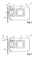
- FIG. 1 schematically a Rangierantrieb 10 is shown, which has a housing 12 and a drive roller 14. Inside the housing 12, an electric motor is arranged in a motor housing 16, which is connected via a gear to the drive roller 14. For power supply, a battery (not shown) is provided.
- the Rangierantrieb serves to a trailer, especially a caravan or the like, then electrically operated to adjust when the trailer is not coupled to the tractor.
- the shunting drive can be used in particular to maneuver it in a campsite and to move into the final position.
- the Rangierantrieb 10 is when it is not needed (ie in particular when the trailer is coupled to a tractor), in a starting position in which the drive roller 14 at a distance from a in FIG. 1 schematically shown wheel 18 of the trailer is located.
- the Rangierantrieb is off the in FIG. 1 shown initial position brought into a Rangier ein in which the drive roller 14 engages the wheel 18 of the trailer.
- a pressure mechanism is provided with which the Rangierantrieb either translationally or rotationally can be adjusted so that the drive roller 14 is applied to the running surface of the wheel 18.
- a splash guard 20 is provided which is intended to prevent water, dirt or pebbles, which are whirled up by the wheel 18 of the trailer while driving, being thrown in the direction of a vehicle following behind.
- the splash guard 20 is thus seen in the direction of travel of the trailer just behind the wheel 18 of the trailer attached.
- a uniaxial trailer will have a splash guard on each side of the trailer.
- either a single splash guard may be mounted behind the rearmost wheel, or each of the wheels of each vehicle side may be associated with a splash guard.
- a rubber or plastic mat can be used, as they are basically known for the same purpose in trucks.
- the splash guard 20 is attached to a suspension 22. This can be assigned to the wheelhouse of the trailer, the frame of the trailer or the Rangierantrieb 10.
- the splash guard 20 this is located immediately behind the wheel 18 and thus between the running surface of the wheel 18 and the drive roller 14 when the Rangierantrieb 10 is in the starting position.
- the splash guard 20 In order to operate the shunting drive, the splash guard 20 must be removed from the area between the running surface of the wheel 18 and the drive roller 14.
- the suspension 22 is designed to be movable, so that the splash guard 20 from the initial position in which it is located between the wheel 18 and the drive roller 14, can be adjusted to a Rangier ein in which the drive roller 14 unhindered by the splash guard with the Tread of the wheel 18 can be engaged.
- a hook 24 is provided, to which the lower end of the splash guard 20 can be attached when it is in the Rangier too.
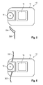
- the splash guard 20 is not moved substantially in the vertical direction, but pulled laterally in the direction of the arrow P from the space between the running surface of the wheel 18 and the drive roller 14.
- a rail can be used, for example, an aluminum profile, in which the thickened upper edge of the splash guard is inserted laterally. This edge can for example be provided with a piping.
- a locking mechanism may be provided, such as a strap or snap spring or a snap hook with which the splash guard 20 can be locked in the rail and can be easily solved by hand.
- sensors may be provided which detect in which position the splash guard is currently located. If an operator wants to move the maneuvering drive from the initial position to the maneuvering position while the splash guard 20 is still in the starting position, a warning signal can be output.
- the splash guard 20 and in particular its suspension 22 is coupled to the Rangierantrieb 10 and its pressure mechanism that it is automatically adjusted from the starting position to the Rangier ein (symbolized by the two parts A) when the drive roller 14 from the starting position is moved to the Rangier ein (symbolized by the arrow P).
- a schematically indicated coupling mechanism 26 may be used, for example, a linkage connection or an adjusting device with servomotor.
- the splash guard 20 can be adjusted by a separate adjustment 28 from the initial position in the Rangier ein. This is triggered separately, for example, by an operator before the shunting drive is activated.
- a warning function can be implemented, which prevents the Rangierantrieb 10 is moved from the starting position to the Rangiergna when the splash guard 20 is still in its initial position.
- the splash guard is made in two parts, namely in the form of a rigid spoiler element 20A, which connects directly to the housing 12 of the Rangierantriebs 10, and to the flexible splash guard element 20B, which is attached to the spoiler element 20A.
- the advantage of this embodiment is that the spoiler does not have to be moved out of the space between the drive roller 14 and the wheel 18 of the trailer before the shunting drive 10 is activated.
- a two-part splash guard is used. This consists here of an upper part 20 C, which is arranged above the drive roller 14, and a lower part 20 D, which is mounted below the drive roller 14. In this way, the entire area behind the wheel 18 is covered, first by the upper part 20C, then by the drive roller 14 and then by the lower part 20D.
- the parts 20C, 20D may be made of different materials.
- a material with less flexibility may be used, for example plastic, while for the lower part 20D rubber or a similarly flexible and impact-damping material is used.
- the two parts 20C, 20D of the spoiler can be exchangeably mounted on the shunting drive 10, for example by a clip connection.
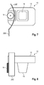
- a splash guard which is composed of a rigid splash guard 20E and a flexible splash guard element 20B.
- the splash guard 20E is designed in the manner of a mudguard or fender and extends around the drive roller 14 around on its side facing away from the wheel 18 side. Also in this embodiment, there is the advantage that the splash guard does not have to be removed or adjusted when the Rangierantrieb 10 is to be activated.
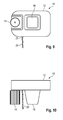
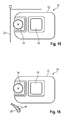
- FIGS. 9 and 10 an embodiment is shown in which a single splash guard 20 is used, which is mounted below the Rangierantriebs 10 here.
- the splash guard 20 is here attached to the underside of the housing 12 of the Rangierantriebs 10, for example by means of a suspension 22 which is fixedly mounted there and in the lateral direction so far beyond the housing 12 (see FIG. 10 ) that the splash guard 20 laterally protrudes slightly beyond the drive roller 14.
- the splash guard 20 of two sub-elements 20F, 20G is formed, both of which consist of a material with a certain inherent rigidity.
- the lower part 20G may have a lower rigidity towards its lower end or, if it is made, for example, as a two-component part, may be made of a different material, for example rubber.
- the two parts 20F, 20G in the in FIG. 11 Dashed position shown adjusted, so substantially exploded, so that the drive roller 14 centrally between them pass and can engage with the running surface of the wheel 18 in engagement.
- a slotted guide can be used to adjust the two parts 20F, 20G of the splash guard 20. Either a separate drive for the two parts 20F, 20G is provided. Alternatively, it is also possible, via a slotted guide or a lever mechanism, the movement of the Rangierantriebs 10, which performs this, in order to move from the starting position in the Rangier ein to implement in the opening movement of the two parts 20F, 20G.
- the particular advantage of this embodiment is that a pinch protection is realized, since the drive roller is made available shortly before the time at which it engages the wheel 18.
- the splash guard is provided with a predefined opening, for example by means of a perforation, so that an operator when he activates the Rangierantrieb 10, the corresponding part breaks out of the splash guard, thus creating the opening through which the Drive roller 14 of the Rangierantriebs 10 can engage the tread of the wheel 18.
- the splash guard 20 may in particular be designed to be easily interchangeable, for example as a disposable splash tab, which is replaced by a new one each time the opening has been broken out of the splashguard.
- FIG. 15 an embodiment is shown in which the splash guard is adjusted from the initial position shown in solid lines in the Rangier ein dashed lines characterized in that it is folded up and stored, for example, on the Rangierantrieb 10.
- the splash guard 20 can be folded down again.
- FIG. 16 an embodiment is shown in which the splash guard 20 similar to that in in FIG. 5 embodiment shown having a spoiler.
- This is provided here with schematically indicated sensors 40, with which various additional functions can be realized, for example, detection of the road condition, a rattle detection or the like.
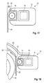
- FIG. 17 an embodiment is shown in which the splash guard 20 is mounted in a suspension 22 similar to earlier embodiments.
- Essential feature of the embodiment according to FIG. 17 is that in the wedge an additional function is integrated.
- the upper end of the splash guard 20 is made thickened, so that a two-stage Auffahrkeil 42 is realized.
- the splash guard can be removed from the suspension 22 and then used to align the trailer horizontally.
- the splash guard 20 may also be configured to be used for covering or closing floor openings, such as the floor panels of an air conditioner. In this way, for example, during winter camping, the heat loss to the environment can be reduced. In the same way as when using the splash guard as Auffahrkeil this is a certain minimum stiffness makes sense.
- FIG. 18 an embodiment is shown in which the splash guard 20 is integrated into the wheel arch 50 of the trailer.
- the suspension 22 is mounted on a bracket 52, which can be adjusted either manually or automatically, to bring the splash guard 20 from the starting position in the Rangier ein.
- a separate drive for example by means of a servo motor, can be used, or the shunting drive 10 can be coupled to the holder 52 via a linkage, a drive cable, etc. such that the holder 52 is appropriately adjusted when the shunting drive 10 is moved from the starting position to the Rangier ein.
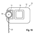
- FIG. 19 an embodiment is shown in which the upper end of the splash guard 20 is provided with a sleeve-shaped Aufsteckabêt 54 which can be pushed onto the drive roller 14 in the axial direction.
- the slip-on portion 54 is flexible and designed with a small undersize relative to the drive roller 14, so that the splash guard 20 is reliably fixed on the drive roller during the drive of the trailer.
- the splash guard 20 is used in this embodiment as a contamination protection for the drive roller 14th
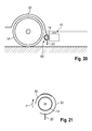
- FIGS. 20 and 21 an embodiment is shown in which the splash guard 20 is attached to a panel 60 which surrounds the drive roller 14.
- the panel 60 (see in particular FIG. 21 ) consists of two shell-like parts 62, 64, of which the part 62 is fixed and surrounds the drive roller 14 by a little more than 180 °.
- the second part 64 is designed to be movable relative to the first part 62 and extends over an angular range such that the drive roller 14, when the part 64 is in the starting position, is completely enclosed together with the fixed part 62.
- the drive roller 14 can be brought into engagement with the running surface of the wheel 18, the second part 64 of the cover 60 can be pivoted relative to the fixed part 62 (see the arrow P in FIG FIG. 21 ), so that the panel is open on the wheel 18 side facing.
- the second part 64 can in particular be pivoted concentrically with the drive roller 14.
- the fixed part 62 is carried out concentrically with the drive roller 14, the overall result is a very compact assembly.
Abstract
Die Erfindung betrifft einen Rangierantrieb (10) für einen Anhänger oder dgl., mit einem Antriebsmotor, einer Antriebsrolle (14) für ein Rad (18) des Anhängers und einem Spritzschutz (20), der mit dem Rangierantrieb zu einer Baugruppe integriert ist.The invention relates to a shunting drive (10) for a trailer or the like., With a drive motor, a drive roller (14) for a wheel (18) of the trailer and a splash guard (20), which is integrated with the Rangierantrieb to an assembly.
Description
Die Erfindung betrifft einen Rangierantrieb für einen Anhänger oder dgl., mit einem Antriebsmotor und einer Antriebsrolle für ein Rad des Anhängers. Die Erfindung betrifft außerdem einen Anhänger mit einem Rangierantrieb.The invention relates to a shunting drive for a trailer or the like., With a drive motor and a drive roller for a wheel of the trailer. The invention also relates to a trailer with a shunting drive.
Von Lastkraftwagen ist bekannt, dass in Fahrtrichtung gesehen hinter den hinteren Rädern ein Spritzschutz angeordnet ist. Dieser ist meist als Gummioder Kunststofflappen ausgeführt und soll verhindern, dass Wasser, Schmutz oder gar Steinchen vom Reifen hin zu einem hinter dem Lastkraftwagen fahrenden Fahrzeug geschleudert werden.From trucks it is known that seen in the direction of travel behind the rear wheels a splash guard is arranged. This is usually designed as a rubber or plastic flap and is intended to prevent water, dirt or even stones being thrown from the tire to a vehicle driving behind the truck.
Die Aufgabe der Erfindung besteht darin, ein hinter dem Anhänger fahrendes Fahrzeug vor Wasser, Schmutz oder gar Steinchen zu schützen, die von den Rädern des Anhängers aufgewirbelt werden.The object of the invention is to protect a behind the trailer moving vehicle from water, dirt or even stones that are whirled up by the wheels of the trailer.
Zur Lösung dieser Aufgabe ist erfindungsgemäß bei einem Rangierantrieb der eingangs genannten Art ein Spritzschutz vorgesehen, der mit dem Rangierantrieb zu einer Baugruppe integriert ist. Die Erfindung beruht auf der Erkenntnis, dass ein solcher Spritzschutz, um effektiv zu sein, möglichst nahe hinter dem (hinteren) Rad des Anhängers angeordnet sein sollte, also in einem Bereich, in welchem sich auch der Rangierantrieb befindet, falls der Anhänger mit einem solchen ausgestattet ist. In diesem Fall ist es besonders vorteilhaft, wenn der Spritzschutz dahingehend mit dem Rangierantrieb zu einer Baugruppe integriert ist, dass er entweder in unmittelbarer Nähe des Rangierantriebs angeordnet oder am Rangierantrieb selbst angebracht ist.To achieve this object, a splash guard according to the invention is provided in a shunting drive of the type mentioned, which is integrated with the Rangierantrieb to form an assembly. The invention is based on the recognition that, in order to be effective, such a splash guard should be arranged as close as possible behind the (rear) wheel of the trailer, ie in a region in which the maneuvering drive is located, if the trailer with such Is provided. In this case, it is particularly advantageous if the splash guard is integrated with the Rangierantrieb to an assembly in that it is either located in the immediate vicinity of the Rangierantriebs or mounted on Rangierantrieb itself.
Vorzugsweise ist vorgesehen, dass der Spritzschutz zwischen einer Ausgangsstellung und einer Rangierstellung bewegbar ist. In der Ausgangsstellung gewährleistet der Spritzschutz einen optimalen Schutz für alle Fahrzeuge, die hinter dem Anhänger fahren. In der Rangierstellung ermöglicht der Spritzschutz, dass die Antriebsrolle des Rangierantriebs ungehindert am Rad des Anhängers angreifen und dieses drehen kann.It is preferably provided that the splash guard between a starting position and a Rangierstellung is movable. In the starting position, the splash guard ensures optimum protection for all vehicles that drive behind the trailer. In the Rangierstellung allows The splash guard that the drive roller of Rangierantriebs unhindered attack on the wheel of the trailer and can turn this.
Gemäß einer Ausgestaltung der Erfindung ist ein Haken vorgesehen, mit dem der Spitzschutz in der Rangierstellung fixierbar ist. Hierbei handelt es sich um eine technisch besonders einfach zu realisierende Lösung, bei der der Spritzschutz bzw. der untere Abschnitt des Spritzschutzes nach oben bewegt und eingehängt wird, sodass die Antriebsrolle ungehindert mit dem Rad des Anhängers in Eingriff gebracht werden kann.According to one embodiment of the invention, a hook is provided, with which the tip protection is fixable in the Rangierstellung. This is a technically particularly easy to implement solution in which the splash guard and the lower portion of the splash guard is moved upwards and hooked so that the drive roller can be freely engaged with the wheel of the trailer.
Gemäß einer alternativen Ausgestaltung ist vorgesehen, dass der Spritzschutz lösbar angebracht ist. Diese Ausgestaltung beruht auf dem Grundgedanken, den Spritzschutz im Normalbetrieb, also wenn der Anhänger gezogen wird, in einer geeigneten Position am Anhänger oder am Rangierantrieb angebracht ist. Wenn der Anhänger allerdings mittels des Rangierantriebs verfahren werden soll, wird der Spritzschutz gelöst und entfernt, sodass die Antriebsrolle ungehindert am Rad des Anhängers angreifen kann.According to an alternative embodiment it is provided that the splash guard is detachably attached. This embodiment is based on the idea that the splash guard in normal operation, so when the trailer is pulled, is mounted in a suitable position on the trailer or on Rangierantrieb. However, if the trailer is to be moved by means of the Rangierantriebs, the splash guard is loosened and removed, so that the drive roller can freely attack on the wheel of the trailer.
Gemäß einer Ausgestaltung ist eine Clipsverbindung vorgesehen, mittels der der Spritzschutz angeclipst werden kann. Alternativ ist eine Halterung vorgesehen, in die der Spritzschutz seitlich einschiebbar ist. Bei beiden Ausgestaltungen ist ein geringer technischer Aufwand nötig, um den Spritzschutz am Anhänger oder am Rangierantrieb anzubringen. Besonders vorteilhaft ist auch, dass der Spritzschutz ohne Werkzeug angebracht bzw. gelöst werden kann.According to one embodiment, a clip connection is provided, by means of which the splash guard can be clipped. Alternatively, a holder is provided, in which the splash guard is inserted laterally. In both embodiments, a small amount of technical effort is required to attach the splash guard on the trailer or the Rangierantrieb. It is also particularly advantageous that the splash guard can be attached or detached without tools.
Gemäß einer alternativen Ausführungsform ist vorgesehen, dass der Spritzschutz Teil des Rangierantriebs ist. Hierbei ist es nicht mehr nötig, den Spritzschutz dann zu entfernen, wenn der Anhänger mittels des Rangierantriebs verfahren werden soll. Stattdessen ist der Spritzschutz so ausgeführt, dass er das Verfahren des Anhängers mittels des Rangierantriebs nicht behindert.According to an alternative embodiment, it is provided that the splash guard is part of the Rangierantriebs. In this case, it is no longer necessary to remove the splash guard when the trailer is to be moved by means of Rangierantriebs. Instead, the splash guard is designed so that it does not hinder the process of the trailer by means of the Rangierantriebs.
Gemäß einer Ausgestaltung ist vorgesehen, dass der Spritzschutz als Teil eines Gehäuses des Rangierantriebs ausgeführt ist. Der Spritzschutz kann also als Verlängerung oder Vorsprung des Gehäuses ausgeführt sein und auf diese Weise die gewünschte Funktion bereitstellen.According to one embodiment, it is provided that the splash guard is designed as part of a housing of the Rangierantriebs. The splash guard can therefore be designed as an extension or projection of the housing and provide in this way the desired function.
Der Spritzschutz kann alternativ auch am Rangierantrieb angebracht sein, beispielsweise durch eine Schraubverbindung oder Ähnliches. Dies ermöglicht, den Spritzschutz bei Bedarf auszutauschen.The splash guard may alternatively be mounted on the Rangierantrieb, for example by a screw or the like. This allows to replace the splash guard when needed.
Gemäß einer Ausgestaltung der Erfindung ist vorgesehen, dass der Rangierantrieb mit einem Andruckmechanismus versehen ist, mit dem er und damit die Antriebsrolle aus einer Ausgangsstellung in eine Rangierstellung verstellt werden kann, und dass der Spritzschutz so am Rangierantrieb angeordnet ist, dass er sich in der Rangierstellung befindet, wenn sich der Rangierantrieb in der Rangierstellung befindet. Diese Ausführungsform beruht auf dem Grundgedanken, dass eine Verstellbewegung, die der Rangierantrieb ausführt, um die Antriebsrolle gegen das Rad des Anhängers zu drücken, gleichzeitig dafür verwendet wird, den Spritzschutz aus der Ausgangsstellung in die Rangierstellung zu verstellen.According to one embodiment of the invention, it is provided that the Rangierantrieb is provided with a pressure mechanism with which he and thus the drive roller can be adjusted from a starting position to a Rangierstellung, and that the splash guard is arranged on Rangierantrieb that he is in the Rangierstellung is located when the maneuvering drive is in the maneuvering position. This embodiment is based on the basic idea that an adjusting movement, which performs the Rangierantrieb to press the drive roller against the wheel of the trailer, is also used to adjust the splash guard from the starting position to the Rangierstellung.
Gemäß einer alternativen Ausgestaltung ist vorgesehen, dass der Rangierantrieb mit einem Andruckmechanismus versehen ist, mit dem die Antriebsrolle aus einer Ausgangsstellung in eine Rangierstellung verstellt werden kann, und dass der Spritzschutz mit dem Andruckmechanismus gekoppelt ist, sodass er automatisch aus der Ausgangsstellung in die Rangierstellung gebracht wird, wenn die Antriebsrolle aus der Ausgangsstellung in die Rangierstellung gebracht wird. Diese Ausführungsform beruht auf dem Grundgedanken, den Spritzschutz aktiv dann zu verstellen, wenn die Antriebsrolle mit dem Rad des Anhängers in Eingriff gebracht wird. Diese aktive Verstellung kann entweder dadurch erfolgen, dass der Spritzschutz in irgendeiner Weise mit dem Andruckmechanismus gekoppelt ist und dadurch verstellt wird, wenn dieser die Antriebsrolle verstellt, oder dass für den Spritzschutz ein separater Antrieb vorgesehen ist, der dann betätigt wird, wenn auch der Andruckmechanismus betätigt wird.According to an alternative embodiment it is provided that the Rangierantrieb is provided with a pressure mechanism with which the drive roller can be adjusted from a starting position to a Rangierstellung, and that the splash guard is coupled to the pressure mechanism so that it is automatically brought from the starting position in the Rangierstellung is when the drive roller is brought from the initial position in the Rangierstellung. This embodiment is based on the idea to actively adjust the splash guard then, when the drive roller is brought into engagement with the wheel of the trailer. This active adjustment can be done either by the fact that the splash guard is coupled in any way with the pressure mechanism and is thereby adjusted when this adjusts the drive roller, or that a separate drive is provided for the splash guard, which is then actuated, although the pressure mechanism is pressed.
Wenn der Andruckmechanismus betätigt wird, kann der Spritzschutz beispielsweise seitlich aus dem Bereich zwischen der Antriebsrolle und dem Rad verstellt wird, also allgemein in einer Richtung parallel zur Drehachse des Rades des Anhängers. Alternativ kann vorgesehen sein, dass der Spritzschutz in vertikaler Richtung aus dem Bereich zwischen der Antriebsrolle und dem Rad verstellt wird. Es kann auch vorgesehen sein, dass der Spritzschutz zweiteilig so ausgeführt ist, dass die beiden Teile auseinandergezogen werden können, sodass zwischen ihnen ein Freiraum für die Antriebsrolle gebildet wird. Bei dieser Ausgestaltung wird also zwischen den beiden Teilen des Spritzschutzes eine Art Fenster geöffnet, durch das hindurch die Antriebsrolle am Rad des Anhängers angreifen kann.For example, when the pressure mechanism is actuated, the splash guard may be displaced laterally out of the area between the drive roller and the wheel, generally in a direction parallel to the axis of rotation of the trailer wheel. Alternatively it can be provided that the splash guard is adjusted in the vertical direction from the area between the drive roller and the wheel. It can also be provided that the splash guard is made in two parts so that the two parts can be pulled apart, so that between them a space for the drive roller is formed. At this Design is thus opened between the two parts of the splash guard a kind of window through which the drive roller can engage the wheel of the trailer.
Es kann auch vorgesehen sein, dass die Antriebsrolle mit einer Verkleidung versehen ist, welche sie zumindest auf der dem Rad zugewandten Seite verkleidet, und dass der Spritzschutz an der Verkleidung vorgesehen ist. Bei dieser Ausgestaltung kann die Antriebsrolle und damit auch der Rangierantrieb vor Verschmutzungen geschützt werden, wenn sich die Antriebsrolle in der Ausgangsstellung befindet.It can also be provided that the drive roller is provided with a cladding which covers it at least on the wheel-facing side, and that the splash guard is provided on the cladding. In this embodiment, the drive roller and thus also the Rangierantrieb be protected from contamination when the drive roller is in the starting position.
Gemäß einer Weiterbildung dieser Ausführungsform kann vorgesehen sein, dass die Verkleidung aus zumindest zwei Teilen besteht, die relativ zueinander zwischen einer Ausgangsstellung, in der die Antriebsrolle zumindest auf der dem Rad zugewandten Seite umschlossen ist, und einer Rangierstellung verstellbar ist, in der die Antriebsrolle mit dem Rad in Eingriff gebracht werden kann. Eine solche Verkleidung kann mit geringem Aufwand in platzsparender Weise geöffnet werden.According to a development of this embodiment can be provided that the lining consists of at least two parts, which is adjustable relative to each other between a starting position in which the drive roller is at least on the side facing the wheel, and a Rangierstellung adjustable, in which the drive roller the wheel can be engaged. Such a panel can be opened with little effort in a space-saving manner.
Gemäß einer Ausgestaltung kann dabei vorgesehen sein, dass die beiden Teile als ineinander verschiebbare Schalen ausgeführt sind. In diesem Fall ist kein zusätzlicher radialer Freiraum erforderlich, wenn die Verkleidung geöffnet werden muss; die beiden Schalen können konzentrisch relativ zueinander verdreht werden.According to one embodiment, it can be provided that the two parts are designed as shells which can be moved into one another. In this case, no additional radial clearance is required when the panel needs to be opened; the two shells can be rotated concentrically relative to each other.
Gemäß einer alternativen Ausgestaltung der Erfindung ist vorgesehen, dass der Spritzschutz mit einer Öffnung für die Antriebsrolle versehen ist. Bei dieser Ausgestaltung ist es nicht zwingend notwendig, den Spritzschutz zu entfernen oder in einer Rangierstellung zu verstellen; der zum Verfahren des Anhängers nötige Kontakt zwischen Antriebsrolle und Rad des Anhängers erfolgt durch die Öffnung des Spritzschutzes hindurch.According to an alternative embodiment of the invention it is provided that the splash guard is provided with an opening for the drive roller. In this embodiment, it is not absolutely necessary to remove the splash guard or to adjust in a Rangierstellung; The contact between the drive roller and the wheel of the trailer, which is necessary for moving the trailer, is made through the opening of the splash guard.
Es kann auch vorgesehen sein, dass der Spritzschutz nach Art eines Rollos ausgeführt ist, also beispielsweise in vertikaler Richtung aus einer heruntergezogenen Ausgangsstellung in eine eingerollte Rangierstellung verstellbar ist.It can also be provided that the splash guard is designed in the manner of a roller blind, that is, for example, in the vertical direction from a pulled-down starting position in a rolled Rangierstellung is adjustable.
Es kann auch vorgesehen sein, dass der Spritzschutz als Abreißabschnitt einer Rollobahn ausgeführt ist. Dies ermöglicht, einen gerade benutzten Abschnitt der Rollobahn, also den als Spritzschutz wirkenden Abschnitt, dann abzureißen und dadurch zu entfernen, wenn die Antriebsrolle am Rad des Anhängers angreifen soll. Dabei kann der derzeit als Spritzschutz dienende Abschnitt der Rollobahn entweder von Hand abgerissen werden oder auch dadurch, dass er zwischen dem Rad des Anhängers und der Antriebsrolle des Rangierantriebs zunächst eingeklemmt und dann abgerissen wird. Wenn der Anhänger wieder mit der Zugmaschine gekoppelt wird, wird ein "neuer" Abschnitt der Rollobahn nach unten gezogen, sodass wieder ein Spritzschutz vorhanden ist. Es kann auch vorgesehen sein, dass die Rollobahn von einem Antrieb automatisiert um eine vorbestimmte Strecke nach unten verstellt wird.It can also be provided that the splash guard is designed as a tear-off section of a roller blind. This allows a currently used one Section of the roller blind, so the acting as a splash guard section, then tear off and thereby remove when the drive roller to attack on the wheel of the trailer. In this case, the currently serving as a splash guard portion of the roller blind can be either demolished by hand or by the fact that it is first clamped between the wheel of the trailer and the drive roller of the Rangierantriebs and then demolished. When the trailer is coupled back to the tractor, a "new" section of the roller blind is pulled down, so that there is again a splash guard. It can also be provided that the roller blind is automatically adjusted by a drive by a predetermined distance down.
Gemäß einer Ausgestaltung der Erfindung ist der Spritzschutz mit einem Reflektor versehen. Dies erhöht die Verkehrssicherheit.According to one embodiment of the invention, the splash guard is provided with a reflector. This increases traffic safety.
Dem Spritzschutz kann auch ein Sensor zugeordnet sein. Auf diese Weise können zusätzliche Funktionen implementiert werden.The splash guard may also be associated with a sensor. In this way additional functions can be implemented.
Beispielsweise kann der Sensor ein Schlingersensor seiner. Dies ermöglicht, aus den Bewegungen des Spritzschutzes ein eventuelles Schlingern des Anhängers zu erkennen.For example, the sensor may be a roll sensor of its. This makes it possible to detect from the movements of the splash guard a possible rolling of the trailer.
Der Sensor kann auch ein Straßenzustandssensor sein. Die Informationen des Straßenzustandssensors können dann einer Steuerung bereitgestellt werden, die beispielsweise die Federung des Anhängers oder einen Schlingerdämpfer ansteuert.The sensor may also be a road condition sensor. The information of the road condition sensor can then be provided to a controller that controls, for example, the suspension of the trailer or a roll damper.
Es kann auch vorgesehen sein, dass der Sensor ein Neigungssensor ist. Die Signale des Neigungssensors können einem Bediener entweder im Anhänger oder auch an einer Steuerung für den Rangierantrieb zur Verfügung gestellt werden, damit es dem Bediener erleichtert wird, den Anhänger exakt horizontal auszurichten.It can also be provided that the sensor is a tilt sensor. The tilt sensor signals can be provided to an operator either in the trailer or on a control for the shunting drive to make it easier for the operator to orient the trailer exactly horizontally.
Gemäß einer Ausgestaltung der Erfindung ist vorgesehen, dass eine Radverhüllung integriert ist. Dies ist besonders vorteilhaft für sogenannte Dauercamper.According to one embodiment of the invention it is provided that a Radverhüllung is integrated. This is particularly advantageous for so-called permanent campers.
In den Rangierantrieb kann auch ein Spoiler integriert sein. Hierdurch ergeben sich Vorteile für die Aerodynamik.In the Rangierantrieb can also be integrated spoiler. This results in advantages for the aerodynamics.
Es kann auch vorgesehen sein, dass der Spritzschutz eine Oberfläche mit Nanoeffekt aufweist. Dies verringert die Verschmutzungsneigung.It can also be provided that the splash guard has a surface with nano-effect. This reduces the tendency to fouling.
Gemäß einer Ausgestaltung der Erfindung ist vorgesehen, dass der Spritzschutz als Auffahrkeil ausgeführt ist. Dies ermöglicht, den Spritzschutz, wenn er während des Rangierens des Anhängers abgenommen ist, zum horizontalen Ausrichten des Anhängers zu verwenden.According to one embodiment of the invention it is provided that the splash guard is designed as Auffahrkeil. This allows the splash guard to be used for horizontal alignment of the trailer when it is detached during maneuvering of the trailer.
Gemäß einer Ausgestaltung der Erfindung ist vorgesehen, dass der Spritzschutz als Reinigungselement für die Antriebsrolle ausgeführt ist. Dadurch kann die Antriebsrolle dann gereinigt werden, wenn sie entweder nach einer langen Fahrt des Anhängers verschmutzt ist oder nachdem der Anhängers mittels des Rangierantriebs auf einem schmutzigen Untergrund verfahren wurde.According to one embodiment of the invention it is provided that the splash guard is designed as a cleaning element for the drive roller. As a result, the drive roller can be cleaned when it is either dirty after a long drive of the trailer or after the trailer was moved by means of the Rangierantriebs on a dirty surface.
Gemäß einer weiteren Ausgestaltung der Erfindung kann vorgesehen sein, dass der Spritzschutz als Verschlusselement für eine Bodenöffnung des Anhängers ausgeführt ist. In diesem Fall können, beispielsweise im Winterbetrieb, die dann nicht benötigten Auslässe einer Klimaanlage verschlossen werden. Dadurch können Kältebrücken verringert werden.According to a further embodiment of the invention can be provided that the splash guard is designed as a closure element for a bottom opening of the trailer. In this case, for example, in winter operation, the then not required outlets of an air conditioner can be closed. As a result, cold bridges can be reduced.
Zur Lösung der oben genannten Aufgabe ist auch ein Anhänger mit einem Spritzschutz vorgesehen, der zwischen einer Ausgangsstellung und einer Rangierstellung verstellt werden kann, wobei der Spritzschutz aus der Rangierstellung in die Ausgangsstellung gebracht wird, wenn der Anhänger im Zugbetrieb verfahren wird. Dies kann beispielsweise durch eine automatische Steuerung geschehen, die erkennt, dass der Anhänger an eine Zugmaschine angekoppelt ist oder von dieser gezogen wird.To solve the above object, a trailer with a splash guard is provided which can be adjusted between a starting position and a Rangierstellung, the splash guard is brought from the Rangierstellung in the starting position when the trailer is moved in the train operation. This can be done for example by an automatic control that detects that the trailer is coupled to a tractor or pulled by this.
Gemäß einer Ausgestaltung kann vorgesehen sein, dass sich der Spritzschutz automatisch in die Ausgangsstellung verstellt, sobald eine vordefinierte Geschwindigkeitsschwelle überschritten wird. Eine solche Lösung ist besonders bedienerfreundlich, da der Spritzschutz nicht extra ausgefahren werden muss, nachdem der Anhänger rangiert wurde.According to one embodiment, it can be provided that the splash guard is automatically adjusted to the starting position as soon as a predefined speed threshold is exceeded. Such a solution is particularly user-friendly, as the splash guard does not have to be extended separately after the trailer has been shunted.
Gemäß einer vorteilhaften Ausgestaltung ist vorgesehen, dass der Spritzschutz passiv in die Ausgangsstellung verstellt wird. Dies kann insbesondere durch den Fahrtwind oder die Drehung des Reifens erfolgen. Es ist auch denkbar, dass der Spritzschutz dann in die Ausgangsstellung verstellt wird, wenn Regen und/oder Schmutz erfasst wird.According to an advantageous embodiment, it is provided that the splash guard is passively adjusted to the starting position. This can be done in particular by the wind or the rotation of the tire. It is also conceivable that the splash guard is then adjusted to the starting position when rain and / or dirt is detected.
Zur Lösung der oben genannten Aufgabe ist auch ein Anhänger vorgesehen, der einen Rangierantrieb, ein Rad, das von dem Rangierantrieb angetrieben werden kann, einen Radkasten, in dem das Rad angeordnet ist, und einen Spritzschutz aufweist, der in den Radkasten integriert ist. Hinsichtlich der sich ergebenden Vorteile wird auf die obigen Erläuterungen verwiesen.In order to achieve the above-mentioned object, there is also provided a trailer having a shunting drive, a wheel that can be driven by the shunting drive, a wheel well in which the wheel is disposed, and a splash guard integrated with the wheel well. With regard to the resulting advantages, reference is made to the above explanations.
Die Erfindung wird nachfolgend anhand verschiedener Ausführungsformen näher erläutert, die in den beigefügten Zeichnungen dargestellt sind. In diesen zeigen:
-
Figur 1 einen Rangierantrieb gemäß einer ersten Ausführungsform der Erfindung; -
Figur 2 einen Rangierantrieb gemäß einer zweiten Ausführungsform der Erfindung; -
Figur 3 einen Rangierantrieb gemäß einer dritten Ausführungsform der Erfindung; -
Figur 4 einen Rangierantrieb gemäß einer vierten Ausführungsform der Erfindung; -
Figur 5 einen Rangierantrieb gemäß einer fünften Ausführungsform der Erfindung; -
Figur 6 einen Rangierantrieb gemäß einer sechsten Ausführungsform der Erfindung; - die
Figuren 7 und 8 einen Rangierantrieb gemäß einer siebten Ausführungsform der Erfindung in einer Seitenansicht und einer Draufsicht; - die
Figuren 9 und 10 einen Rangierantrieb gemäß einer achten Ausführungsform der Erfindung in einer Seitenansicht und einer Draufsicht; - die
Figuren 11 und 12 einen Rangierantrieb gemäß einer neunten Ausführungsform der Erfindung in einer Draufsicht und einer Seitenansicht; - die
Figuren 13 und 14 einen Rangierantrieb gemäß einer zehnten Ausführungsform der Erfindung in einer Seitenansicht und einer Draufsicht; -
Figur 15 einen Rangierantrieb gemäß einer elften Ausführungsform der Erfindung; -
Figur 16 -
Figur 17 einen Rangierantrieb gemäß einer dreizehnten Ausführungsform der Erfindung; -
Figur 18 -
Figur 19 einen Rangierantrieb gemäß einer fünfzehnten Ausführungsform der Erfindung; -
Figur 20 -
Figur 21 einDetail von Figur 20 .
-
FIG. 1 a shunting drive according to a first embodiment of the invention; -
FIG. 2 a shunting drive according to a second embodiment of the invention; -
FIG. 3 a shunting drive according to a third embodiment of the invention; -
FIG. 4 a shunting drive according to a fourth embodiment of the invention; -
FIG. 5 a shunting drive according to a fifth embodiment of the invention; -
FIG. 6 a shunting drive according to a sixth embodiment of the invention; - the
FIGS. 7 and 8 a shunting drive according to a seventh embodiment of the invention in a side view and a plan view; - the
FIGS. 9 and 10 a shunting drive according to an eighth embodiment of the invention in a side view and a plan view; - the
FIGS. 11 and 12 a shunting drive according to a ninth embodiment of the invention in a plan view and a side view; - the
FIGS. 13 and 14 a shunting drive according to a tenth embodiment of the invention in a side view and a plan view; -
FIG. 15 a shunting drive according to an eleventh embodiment of the invention; -
FIG. 16 a shunting drive according to a twelfth embodiment of the invention; -
FIG. 17 a shunting drive according to a thirteenth embodiment of the invention; -
FIG. 18 a shunting drive according to a fourteenth embodiment of the invention; -
FIG. 19 a shunting drive according to a fifteenth embodiment of the invention; -
FIG. 20 a shunting drive according to an eighteenth embodiment of the invention; and -
FIG. 21 a detail ofFIG. 20 ,
In
Der Rangierantrieb dient dazu, einen Anhänger, insbesondere einen Caravan oder Ähnliches, dann elektrisch betrieben zu verstellen, wenn der Anhänger nicht mit der Zugmaschine gekoppelt ist. Im Falle eines Caravans kann der Rangierantrieb insbesondere dazu verwendet werden, diesen auf einem Campingplatz zu manövrieren und in die endgültige Position zu verfahren.The Rangierantrieb serves to a trailer, especially a caravan or the like, then electrically operated to adjust when the trailer is not coupled to the tractor. In the case of a caravan, the shunting drive can be used in particular to maneuver it in a campsite and to move into the final position.
Der Rangierantrieb 10 befindet sich, wenn er nicht benötigt wird (also insbesondere wenn der Anhänger an eine Zugmaschine gekoppelt ist), in einer Ausgangsstellung, in der die Antriebsrolle 14 sich im Abstand von einem in
Am Anhänger und insbesondere am Rangierantrieb 10 bzw. dem Rangierantrieb 10 zugeordnet ist ein Spritzschutz 20 vorgesehen, der verhindern soll, dass Wasser, Schmutz oder Steinchen, die vom Rad 18 des Anhängers im Fahrbetrieb aufgewirbelt werden, in Richtung eines hinterherfahrenden Fahrzeugs geschleudert werden. Der Spritzschutz 20 ist also in Fahrtrichtung des Anhängers gesehen knapp hinter dem Rad 18 des Anhängers angebracht. Bei einem einachsigen Anhänger wird auf jeder Seite des Anhängers ein Spritzschutz vorgesehen. Bei einem zweiachsigen Anhänger kann entweder ein einziger Spritzschutz hinter dem hintersten Rad angebracht sein, oder jedem der Räder jeder Fahrzeugseite kann ein Spritzschutz zugeordnet sein.Associated with the trailer and in particular with the shunting
Als Spritzschutz kann insbesondere eine Gummi- oder Kunststoffmatte verwendet werden, wie sie grundsätzlich für denselben Einsatzzweck bei Lastkraftwagen bekannt sind.As splash protection, in particular a rubber or plastic mat can be used, as they are basically known for the same purpose in trucks.
Bei der in
Im Hinblick auf die optimale Wirksamkeit des Spritzschutzes 20 ist dieser unmittelbar hinter dem Rad 18 und somit zwischen der Lauffläche des Rades 18 und der Antriebsrolle 14 angeordnet, wenn sich der Rangierantrieb 10 in der Ausgangsstellung befindet.With regard to the optimal effectiveness of the
Um den Rangierantrieb in Betrieb nehmen zu können, muss der Spritzschutz 20 aus dem Bereich zwischen der Lauffläche des Rades 18 und der Antriebsrolle 14 entfernt werden. Zu diesem Zweck ist die Aufhängung 22 hier bewegbar ausgeführt, sodass der Spritzschutz 20 aus der Ausgangsstellung, in der er sich zwischen dem Rad 18 und der Antriebsrolle 14 befindet, in eine Rangierstellung verstellt werden kann, in der die Antriebsrolle 14 ungehindert vom Spritzschutz mit der Lauffläche des Rades 18 in Eingriff gebracht werden kann. Bei dieser Ausführungsform ist hier ein Haken 24 vorgesehen, an dem das untere Ende des Spritzschutzes 20 befestigt werden kann, wenn dieser sich in der Rangierstellung befindet.In order to operate the shunting drive, the
Bei der in
Zur Anbringung des Spritzschutzes 20 bei der zweiten Ausführungsform kann eine Profilschiene verwendet werden, beispielsweise ein Alu-Profil, in das der verdickte obere Rand des Spritzschutzes seitlich eingeschoben wird. Dieser Rand kann beispielsweise mit einem Keder versehen sein. An der Profilschiene kann ein Verriegelungsmechanismus vorgesehen sein, beispielsweise eine Bügel- oder Schnappfeder oder ein Schnapphaken, mit dem der Spritzschutz 20 in der Profilschiene verriegelt werden kann und der leicht von Hand gelöst werden kann.For attachment of the
Bei beiden Ausführungsformen können (nicht dargestellte) Sensoren vorgesehen sein, die erfassen, in welcher Position sich der Spritzschutz gerade befindet. Falls ein Bediener den Rangierantrieb aus der Ausgangsstellung in die Rangierstellung bringen möchte, während der Spritzschutz 20 sich noch in der Ausgangsstellung befindet, kann ein Warnsignal ausgegeben werden.In both embodiments, sensors (not shown) may be provided which detect in which position the splash guard is currently located. If an operator wants to move the maneuvering drive from the initial position to the maneuvering position while the
Es ist auch möglich, dass ein Bediener, wenn er den Rangierantrieb aus der Rangierstellung in die Ausgangsstellung zurückgestellt hat, optisch und/oder akustisch daran erinnert wird, dass der Spritzschutz wieder in die Ausgangsstellung gebracht werden muss, also bei der ersten Ausführungsform vom Haken 24 gelöst werden muss und bei der zweiten Ausführungsform in die Profilschiene eingeschoben werden muss.It is also possible for an operator, when he has returned the shunting drive from the maneuvering position to the starting position, to be visually and / or acoustically reminded that the splashguard must be brought back into the starting position, ie in the first embodiment from the
Bei der dritten Ausführungsform ist der Spritzschutz 20 und insbesondere seine Aufhängung 22 so mit dem Rangierantrieb 10 und dessen Andruckmechanismus gekoppelt, dass er automatisch aus der Ausgangsstellung in die Rangierstellung verstellt wird (symbolisiert durch die beiden Teile A), wenn die Antriebsrolle 14 aus der Ausgangsstellung in die Rangierstellung verstellt wird (symbolisiert durch den Pfeil P). Hierdurch kann ein nur schematisch angedeuteter Koppelmechanismus 26 verwendet werden, beispielsweise eine Gestängeverbindung oder auch eine Verstellvorrichtung mit Servomotor.In the third embodiment, the
Bei der Ausführungsform gemäß
Bei der vierten Ausführungsform kann eine Warnfunktion implementiert sein, die verhindert, dass der Rangierantrieb 10 aus der Ausgangsstellung in die Rangierstellung verstellt wird, wenn sich der Spritzschutz 20 weiterhin in seiner Ausgangsstellung befindet.In the fourth embodiment, a warning function can be implemented, which prevents the
Bei der Ausführungsform gemäß
Bei der in
Die Teile 20C, 20D können aus unterschiedlichen Materialien bestehen. Beispielsweise kann für den oberen Teil 20C ein Material mit geringerer Flexibilität verwendet werden, beispielsweise Kunststoff, während für den unteren Teil 20D Gummi oder ein ähnlich flexibles und aufschlagdämpfendes Material verwendet wird.The
Auch bei der Ausführungsform gemäß
Die beiden Teile 20C, 20D des Spoilers können austauschbar am Rangierantrieb 10 angebracht sein, beispielsweise durch eine Clipsverbindung.The two
In den
In den
In den
In der in
Wenn der Rangierantrieb 10 aus der Ausgangsstellung in die Rangierstellung verstellt wird, werden die beiden Teile 20F, 20G in die in
Zum Verstellen der beiden Teile 20F, 20G des Spritzschutzes 20 kann eine Kulissenführung verwendet werden. Entweder wird ein separater Antrieb für die beiden Teile 20F, 20G vorgesehen. Alternativ ist auch möglich, über eine Kulissenführung oder einen Hebelmechanismus die Bewegung des Rangierantriebs 10, die dieser ausführt, um aus der Ausgangsstellung in die Rangierstellung zu gelangen, in die Öffnungsbewegung der beiden Teile 20F, 20G umzusetzen.To adjust the two
Der besondere Vorteil dieser Ausgestaltung liegt darin, dass ein Einklemmschutz realisiert wird, da die Antriebsrolle erst kurz vor dem Zeitpunkt zugänglich gemacht wird, zu dem sie am Rad 18 angreift.The particular advantage of this embodiment is that a pinch protection is realized, since the drive roller is made available shortly before the time at which it engages the
In den
Bei dieser Ausführungsform kann der Spritzschutz 20 insbesondere leicht austauschbar ausgeführt sein, beispielsweise als Einwegspritzlappen, der jedes Mal dann durch einen neuen ersetzt wird, wenn die Öffnung aus dem Spritzschutz herausgebrochen wurde.In this embodiment, the
In
In
In
Bei der gezeigten Ausführungsform ist das obere Ende des Spritzschutzes 20 verdickt ausgeführt, sodass ein zweistufiger Auffahrkeil 42 verwirklicht ist. Der Spritzschutz kann also, wenn der Rangierantrieb 10 aktiviert werden soll, von der Aufhängung 22 entfernt und dann dazu verwendet werden, den Anhänger horizontal auszurichten.In the embodiment shown, the upper end of the
Der Spritzschutz 20 kann auch so ausgestaltet werden, dass er zum Abdecken oder Verschließen von Bodenöffnungen verwendet werden kann, beispielsweise den Bodenausschnitten einer Klimaanlage. Auf diese Weise kann beispielsweise beim Wintercamping der Wärmeverlust an die Umgebung verringert werden. In gleicher Weise wie bei der Verwendung des Spritzschutzes als Auffahrkeil ist hierfür eine gewisse Mindeststeifigkeit sinnvoll.The
In
Es ist auch möglich, die Halterung 52 passiv zu verstellen, beispielsweise in Abhängigkeit vom Fahrtwind oder einer Drehung des Rades 18. Dies gewährleistet, dass der Spritzschutz 20 automatisch in die Ausgangsstellung zurückgestellt wird, wenn der Anhänger im Zugbetrieb bewegt wird.It is also possible to adjust the
In
Bei dieser manuellen Lösung wird ein Bediener intuitiv beim Aktivieren des Rangierantriebs 10 daran erinnert, dass der Spritzschutz 20 von der Antriebsrolle 14 abgenommen werden muss, damit diese mit der Lauffläche des Rades 18 in Eingriff gebracht werden kann. Außerdem dient der Spritzschutz 20 bei dieser Ausführungsform als Verschmutzungsschutz für die Antriebsrolle 14.In this manual approach, an operator is intuitively reminded upon activation of the maneuvering drive 10 that the
In den
Claims (35)
Applications Claiming Priority (1)
| Application Number | Priority Date | Filing Date | Title |
|---|---|---|---|
| DE201420100738 DE202014100738U1 (en) | 2014-02-19 | 2014-02-19 | Rangierantrieb with splash guard for Anhänder or the like. |
Publications (1)
| Publication Number | Publication Date |
|---|---|
| EP2910457A1 true EP2910457A1 (en) | 2015-08-26 |
Family
ID=50480221
Family Applications (1)
| Application Number | Title | Priority Date | Filing Date |
|---|---|---|---|
| EP15155577.8A Withdrawn EP2910457A1 (en) | 2014-02-19 | 2015-02-18 | Manoeuvring drive with splash guard for trailers and the like. |
Country Status (2)
| Country | Link |
|---|---|
| EP (1) | EP2910457A1 (en) |
| DE (1) | DE202014100738U1 (en) |
Cited By (3)
| Publication number | Priority date | Publication date | Assignee | Title |
|---|---|---|---|---|
| USD905217S1 (en) | 2018-09-05 | 2020-12-15 | Dometic Sweden Ab | Air conditioning apparatus |
| USD907183S1 (en) | 2016-11-23 | 2021-01-05 | Dometic Sweden Ab | Air conditioning apparatus |
| US11772452B2 (en) | 2017-11-16 | 2023-10-03 | Dometic Sweden Ab | Air conditioning apparatus for recreational vehicles |
Families Citing this family (3)
| Publication number | Priority date | Publication date | Assignee | Title |
|---|---|---|---|---|
| DE202014101524U1 (en) * | 2014-03-31 | 2015-04-02 | Reich Kg, Regel- Und Sicherheitstechnik | Auxiliary drive for a trailer and trailer |
| DE202014101955U1 (en) * | 2014-04-25 | 2015-07-16 | Alois Kober Gmbh | Splash guard for trailer with maneuvering aid |
| DE202018101924U1 (en) * | 2018-04-10 | 2019-04-11 | Reich Gmbh Regel- Und Sicherheitstechnik | Auxiliary drive for a vehicle, in particular for a trailer, and trailers |
Citations (6)
| Publication number | Priority date | Publication date | Assignee | Title |
|---|---|---|---|---|
| EP1447312A1 (en) * | 2003-02-13 | 2004-08-18 | Reich KG | Manoeuvring device for non-driven vehicles |
| EP1714858A1 (en) * | 2005-04-18 | 2006-10-25 | Truma Gerätetechnik GmbH & Co. KG | Auxiliary drive for a trailer with an unilaterally supported driving roller |
| EP1764274A1 (en) * | 2005-09-16 | 2007-03-21 | Purple Line Limited | Apparatus for moving trailers |
| EP2028085A1 (en) * | 2007-08-23 | 2009-02-25 | Reich GmbH | Auxiliary drive for a caravan |
| GB2457725A (en) * | 2008-02-25 | 2009-08-26 | James Richard Yates | Machines for manoeuvring trailers |
| EP2669157A2 (en) * | 2012-05-29 | 2013-12-04 | Truma Gerätetechnik GmbH & Co. KG | Trailer manoeuvring drive |
-
2014
- 2014-02-19 DE DE201420100738 patent/DE202014100738U1/en not_active Expired - Lifetime
-
2015
- 2015-02-18 EP EP15155577.8A patent/EP2910457A1/en not_active Withdrawn
Patent Citations (6)
| Publication number | Priority date | Publication date | Assignee | Title |
|---|---|---|---|---|
| EP1447312A1 (en) * | 2003-02-13 | 2004-08-18 | Reich KG | Manoeuvring device for non-driven vehicles |
| EP1714858A1 (en) * | 2005-04-18 | 2006-10-25 | Truma Gerätetechnik GmbH & Co. KG | Auxiliary drive for a trailer with an unilaterally supported driving roller |
| EP1764274A1 (en) * | 2005-09-16 | 2007-03-21 | Purple Line Limited | Apparatus for moving trailers |
| EP2028085A1 (en) * | 2007-08-23 | 2009-02-25 | Reich GmbH | Auxiliary drive for a caravan |
| GB2457725A (en) * | 2008-02-25 | 2009-08-26 | James Richard Yates | Machines for manoeuvring trailers |
| EP2669157A2 (en) * | 2012-05-29 | 2013-12-04 | Truma Gerätetechnik GmbH & Co. KG | Trailer manoeuvring drive |
Cited By (4)
| Publication number | Priority date | Publication date | Assignee | Title |
|---|---|---|---|---|
| USD907183S1 (en) | 2016-11-23 | 2021-01-05 | Dometic Sweden Ab | Air conditioning apparatus |
| US11772452B2 (en) | 2017-11-16 | 2023-10-03 | Dometic Sweden Ab | Air conditioning apparatus for recreational vehicles |
| USD905217S1 (en) | 2018-09-05 | 2020-12-15 | Dometic Sweden Ab | Air conditioning apparatus |
| USD944374S1 (en) | 2018-09-05 | 2022-02-22 | Dometic Sweden Ab | Air conditioning apparatus |
Also Published As
| Publication number | Publication date |
|---|---|
| DE202014100738U1 (en) | 2014-03-20 |
Similar Documents
| Publication | Publication Date | Title |
|---|---|---|
| DE102004041709C5 (en) | Vehicle with automatic opening flap | |
| EP2910457A1 (en) | Manoeuvring drive with splash guard for trailers and the like. | |
| EP2454435B1 (en) | Modular unit with sensor device | |
| DE102004049054A1 (en) | Accident warning system for vehicles, registers obstacles within reach of door when swung open and warns occupants of danger or impending hazard | |
| DE202005006903U1 (en) | Collision protection device for motor driven motor vehicle external mirrors has distance sensor and control unit to turn mirror and avoid collision with an object | |
| DE102005048142A1 (en) | Towing vehicle for towing vehicle-trailer combination, has wind diffusing system including side flap and roof spoiler that are adjustable between retracted position and extended position in vehicle longitudinal direction | |
| DE102007043477B4 (en) | Motor vehicle with a power-driven tailgate | |
| DE102005022421A1 (en) | Collision avoidance system for use on commercial road vehicles uses inputs from distance sensors to provide guidance information | |
| DE19901016B4 (en) | commercial vehicle | |
| DE10304707B3 (en) | Outward swinging door mechanism for road vehicle has linkage with sensor and control mechanism holding cab door parallel to bodywork and moving it out and back to clear front wheel | |
| DE19546559C1 (en) | Cover for recessed grip for vehicle door | |
| DE102005000944A1 (en) | Lorry | |
| DE4134501A1 (en) | Semi-trailer lorry - has steering axle with steering servo unit, with generated steering force limited by e.g. pressure limitation valve | |
| DE202010008150U1 (en) | Device for folding an exterior mirror in motor vehicles | |
| DE4331613C2 (en) | Short coupling system | |
| EP3287347B1 (en) | Auxiliary drive for a trailer and trailer | |
| EP0361166A1 (en) | Adjusting device for the two external rearview mirrors of a tractor vehicle in a tractor-trailer combination | |
| EP2952421B1 (en) | Auxiliary drive for a trailer and trailer | |
| DE3401521A1 (en) | MUDGUARDS FOR VEHICLES, ESPECIALLY FOR THE REAR WHEELS OF SEMI-TRAILER | |
| DE19936578A1 (en) | Rear view mirror arrangement has automatic adjustment for motor vehicles with trailers that adjusts mirror angle automatically depending on bend angle of vehicle about linkage rotation point | |
| DE102004037959A1 (en) | System for automatic adjustment of external mirror for vehicle with trailer comprises a control equipment with sensor mounted on vehicle bottom plate which detects turning movement of vehicle about its vertical axis | |
| DE102012013848A1 (en) | Front mudguard for motor car, has air guide element protruded from mudguard surface in functional position of air guide element such that air resistance and output of gearbox in motor car are increased in mounted state of mudguard | |
| DE102007052617A1 (en) | Motor vehicle, has camera that monitors surrounding associated with mirror and is rearwardly moveable together with mirror from retracted position to withdrawn position, and servo motor for tilting mirror relative to optical axis of camera | |
| EP3093223B1 (en) | Vehicle combination consisting of a traction vehicle and trailing vehicle, in particular a semi-trailer | |
| DE202014010001U1 (en) | Exterior mirrors II |
Legal Events
| Date | Code | Title | Description |
|---|---|---|---|
| PUAI | Public reference made under article 153(3) epc to a published international application that has entered the european phase |
Free format text: ORIGINAL CODE: 0009012 |
|
| AK | Designated contracting states |
Kind code of ref document: A1 Designated state(s): AL AT BE BG CH CY CZ DE DK EE ES FI FR GB GR HR HU IE IS IT LI LT LU LV MC MK MT NL NO PL PT RO RS SE SI SK SM TR |
|
| AX | Request for extension of the european patent |
Extension state: BA ME |
|
| STAA | Information on the status of an ep patent application or granted ep patent |
Free format text: STATUS: THE APPLICATION IS DEEMED TO BE WITHDRAWN |
|
| 18D | Application deemed to be withdrawn |
Effective date: 20160227 |