EP4068030B1 - Verpackungsanlage und verfahren mit fehleranalyse - Google Patents
Verpackungsanlage und verfahren mit fehleranalyse Download PDFInfo
- Publication number
- EP4068030B1 EP4068030B1 EP22164610.2A EP22164610A EP4068030B1 EP 4068030 B1 EP4068030 B1 EP 4068030B1 EP 22164610 A EP22164610 A EP 22164610A EP 4068030 B1 EP4068030 B1 EP 4068030B1
- Authority
- EP
- European Patent Office
- Prior art keywords
- packaging system
- stop
- packaging
- performance
- display
- Prior art date
- Legal status (The legal status is an assumption and is not a legal conclusion. Google has not performed a legal analysis and makes no representation as to the accuracy of the status listed.)
- Active
Links
Images

Classifications
-
- G—PHYSICS
- G05—CONTROLLING; REGULATING
- G05B—CONTROL OR REGULATING SYSTEMS IN GENERAL; FUNCTIONAL ELEMENTS OF SUCH SYSTEMS; MONITORING OR TESTING ARRANGEMENTS FOR SUCH SYSTEMS OR ELEMENTS
- G05B23/00—Testing or monitoring of control systems or parts thereof
- G05B23/02—Electric testing or monitoring
- G05B23/0205—Electric testing or monitoring by means of a monitoring system capable of detecting and responding to faults
- G05B23/0259—Electric testing or monitoring by means of a monitoring system capable of detecting and responding to faults characterized by the response to fault detection
- G05B23/0275—Fault isolation and identification, e.g. classify fault; estimate cause or root of failure
-
- B—PERFORMING OPERATIONS; TRANSPORTING
- B65—CONVEYING; PACKING; STORING; HANDLING THIN OR FILAMENTARY MATERIAL
- B65B—MACHINES, APPARATUS OR DEVICES FOR, OR METHODS OF, PACKAGING ARTICLES OR MATERIALS; UNPACKING
- B65B57/00—Automatic control, checking, warning, or safety devices
- B65B57/18—Automatic control, checking, warning, or safety devices causing operation of audible or visible alarm signals
-
- B—PERFORMING OPERATIONS; TRANSPORTING
- B65—CONVEYING; PACKING; STORING; HANDLING THIN OR FILAMENTARY MATERIAL
- B65B—MACHINES, APPARATUS OR DEVICES FOR, OR METHODS OF, PACKAGING ARTICLES OR MATERIALS; UNPACKING
- B65B35/00—Supplying, feeding, arranging or orientating articles to be packaged
- B65B35/10—Feeding, e.g. conveying, single articles
- B65B35/24—Feeding, e.g. conveying, single articles by endless belts or chains
-
- B—PERFORMING OPERATIONS; TRANSPORTING
- B65—CONVEYING; PACKING; STORING; HANDLING THIN OR FILAMENTARY MATERIAL
- B65B—MACHINES, APPARATUS OR DEVICES FOR, OR METHODS OF, PACKAGING ARTICLES OR MATERIALS; UNPACKING
- B65B57/00—Automatic control, checking, warning, or safety devices
- B65B57/10—Automatic control, checking, warning, or safety devices responsive to absence, presence, abnormal feed, or misplacement of articles or materials to be packaged
- B65B57/12—Automatic control, checking, warning, or safety devices responsive to absence, presence, abnormal feed, or misplacement of articles or materials to be packaged and operating to control, or stop, the feed of wrapping materials, containers, or packages
-
- B—PERFORMING OPERATIONS; TRANSPORTING
- B65—CONVEYING; PACKING; STORING; HANDLING THIN OR FILAMENTARY MATERIAL
- B65B—MACHINES, APPARATUS OR DEVICES FOR, OR METHODS OF, PACKAGING ARTICLES OR MATERIALS; UNPACKING
- B65B57/00—Automatic control, checking, warning, or safety devices
- B65B57/10—Automatic control, checking, warning, or safety devices responsive to absence, presence, abnormal feed, or misplacement of articles or materials to be packaged
- B65B57/14—Automatic control, checking, warning, or safety devices responsive to absence, presence, abnormal feed, or misplacement of articles or materials to be packaged and operating to control, or stop, the feed of articles or material to be packaged
-
- G—PHYSICS
- G05—CONTROLLING; REGULATING
- G05B—CONTROL OR REGULATING SYSTEMS IN GENERAL; FUNCTIONAL ELEMENTS OF SUCH SYSTEMS; MONITORING OR TESTING ARRANGEMENTS FOR SUCH SYSTEMS OR ELEMENTS
- G05B23/00—Testing or monitoring of control systems or parts thereof
- G05B23/02—Electric testing or monitoring
- G05B23/0205—Electric testing or monitoring by means of a monitoring system capable of detecting and responding to faults
- G05B23/0259—Electric testing or monitoring by means of a monitoring system capable of detecting and responding to faults characterized by the response to fault detection
- G05B23/0267—Fault communication, e.g. human machine interface [HMI]
-
- G—PHYSICS
- G05—CONTROLLING; REGULATING
- G05B—CONTROL OR REGULATING SYSTEMS IN GENERAL; FUNCTIONAL ELEMENTS OF SUCH SYSTEMS; MONITORING OR TESTING ARRANGEMENTS FOR SUCH SYSTEMS OR ELEMENTS
- G05B2219/00—Program-control systems
- G05B2219/30—Nc systems
- G05B2219/45—Nc applications
- G05B2219/45048—Packaging
Definitions
- the invention relates to a packaging system having the features of the preamble of claim 1 and to a method for operating a packaging system.
- a packaging system is understood to be a system that has at least one packaging machine (i.e. a machine in which products are packaged in packaging material) and at least one further component in addition to the packaging machine.
- this further component can be any machine or station that acts in some way on the products and/or the packaging material.
- the additional component can be a transport device for transporting products, for example a feed conveyor, a conveyor belt, a transfer robot, such as a delta or scara robot or similar.
- the further component can also be, for example, a printing device for applying pressure to packaging material, a testing device such as a vision system or a check weigher, or even a labeler.
- the component of the packaging system provided in addition to the packaging machine can also be a filler for filling packaging with a product.
- the packaging system can have one or more such additional components.
- Packaging systems with a packaging machine and at least one other component are based, for example, on the EN 10 2018 222 397 A1 , the EN 10 2018 214 761 A1 or the EN 10 2017 124 650 A1 out.
- Such packaging systems typically have a nominal output, i.e. an output that can be achieved in trouble-free normal operation, i.e. a number of finished packages per unit of time (for example per minute).
- the actual output of the packaging system can be subject to fluctuations and can fluctuate around the nominal output in particular. It becomes critical when a reduced output occurs.
- a "reduced output" can be defined as an output of, for example, 95% or less of the nominal output, or of 90% or less of the nominal output.
- a special case of a reduced output is a stop of the packaging system, i.e. a reduction of the current output of the packaging system to zero.
- a reduced output or even a stop of the packaging system can have a variety of causes.
- the WO 2005/031485 A1 discloses a display and operating unit for a machine in the tobacco processing industry. When a machine stops, the operator is shown a reason for the machine stop in a message area of a display.
- the EP 2 075 661 A1 describes a packaging line architecture in which performance analysis is to be carried out in real time.
- the EN 10 2017 007 909 A1 describes a production control system for manufacturing facilities, in which the causes for a stop of the production system are to be identified.
- the EN 10 2018 122 213 A1 describes another device for monitoring and documenting manufacturing processes in which an operator can manually enter sources of errors in a list.
- the object of the present invention is to improve a packaging system and a method for operating a packaging system in such a way that the average performance of the packaging system is increased.
- the packaging system is configured to show a performance graph on the display.
- the performance graph shows, preferably in real time, a current performance of the packaging system, preferably also the course of the actually achieved performance over a certain period of time going back into the past. For example, the performance could be shown as a percentage of the nominal performance.
- the number of cycles in a given period of time can be used, multiplied by the number of packages produced in one format or in one cycle.
- the computer unit of the packaging system has an error analysis section that is designed to detect a stop or a reduced performance of the packaging system.
- a reduced performance can be defined, for example, as a performance of a maximum of 95% or a maximum of 90% of the nominal performance of the packaging system.
- the reduced performance can be viewed as an actual performance below a certain performance threshold.
- a stop of the packaging system leads to a performance of zero and thus to an extreme case of reduced performance.
- the error analysis section is designed to identify, when a stop or generally a reduction in performance is detected, an error source that caused the stop or the reduction in performance in question from an error source list stored in a memory.
- the error source list can contain any discrete number of potential error sources.
- the error source list can be stored in the form of a list, an array, a table or similar. It can preferably contain the most common error sources that can cause a stop or a reduction in performance.
- the identification of the causal error source can be carried out taking into account the information as to whether the packaging machine or a specific other component of the packaging system caused the stop or the reduction in performance, for example based on control or sensor signals received there.
- the packaging system is configured to show the identified source of the error on the display. This allows the operator of the packaging system to immediately identify the source of the error and the component or machine causing the error without having to search for it for a long time. This speeds up the elimination of the error and reduces downtime or periods of reduced performance of the packaging system, which overall significantly increases the average performance of the packaging system.
- the packaging system can also be configured to generate an evaluation or statistics of reduced performance and its causes. This allows the operation of the packaging system to be further optimized, for example by systematically identifying the causes of particularly common sources of error and avoiding these causes through countermeasures.
- Sources of error leading to a stop can be, for example, the complete failure (or loss of power) of a component or the packaging machine, or reaching the end of the film (no more material) of a bottom or lid film.
- messages from the system or its components are to be understood as synonymous with “errors” insofar as they refer to the reporting of an event or a condition that has led to a stop or reduced performance.
- the stored error source list can therefore also be or include a list of potential messages.
- the error analysis section is configured to store a time stamp associated with a detected stop or a detected underperformance of the packaging system.
- the time stamp can be the time (in hours, minutes, possibly seconds), possibly plus the date, of the point in time at which a stop or underperformance occurred or was detected.
- the time stamp can also indicate the duration of a stop or underperformance. In this context, assignment means that the time stamp is associated with a specific stop or underperformance.
- the performance graph includes a representation of the performance of the packaging system or the packaging machine over a time axis. In such a two-dimensional representation, the course of the performance over a certain period of time can be read.
- At least one sensor is connected to the computer unit.
- the computer can monitor parameters and report them to the computer unit in the form of sensor signals that allow conclusions to be drawn about a performance, a lack of performance, a stop or the error underlying a stop or a lack of performance, for example temperatures, electrical currents, electrical voltages, mechanical tensions, pressures, etc.
- the signal received from the sensor can be passed on to the error analysis section.
- the packaging system can also be configured to show fault messages and/or warnings on the display. This makes it easier for the operator to identify a fault.
- the display can be arranged on or in the packaging machine. This has the advantage that the operator will often be at the packaging machine or in its vicinity and can easily see the display here.
- the display or another display can also be located away from the packaging machine, for example in a control room in which the display can be connected to the packaging machine and the additional component(s) of the packaging system via a data network (wired or wireless) or a cloud connection, or on a mobile device.
- the computer unit and/or the error analysis section can also be arranged on or in the packaging machine or on or in one of the other components of the packaging system.
- the computer unit and/or the error analysis section (or parts thereof) can also be located away from the packaging machine, for example in a control room or on a mobile device, and integrated into the packaging system via a wired or wireless data connection.
- the invention also relates to a method for operating a packaging system, in which a performance graph is shown on a display of the packaging system, a list of error sources is stored in a memory, an error analysis section of a computer unit identifies an error source that is the cause of the stop or the reduced performance in question from the error source list in the event of a stop or reduced performance of the packaging system, and the identified source of the error is finally shown on the display.
- error source list can be edited.
- error sources can be specified in this way and/or additional error sources can be added to the list.
- the error source list can preferably be edited from the display.
- the performance graph comprises a representation of a performance of the packaging system or the packaging machine over a time axis, again with the advantages described above.
- the performance graph is updated continuously or intermittently. If the packaging machine or the packaging system as a whole works intermittently or intermittently, the intermittent updating of the performance graph can be synchronized with the work cycle of the packaging system or machine.
- recipe changes and/or parameter changes are shown on the display in or together with the performance graph. This increases the amount of information made available to the operator and can make it even easier to find an error.
- a point in time at which a stop or a drop in performance occurs is recorded and stored, ideally in association with a specific stop or a drop in performance. Additionally or alternatively, it is conceivable that a period or the duration of a stop or a drop in performance is recorded and stored, again ideally in association with a specific stop or a drop in performance.
- the packaging machine can be, for example, a tray sealing machine or a thermoforming packaging machine. It is also conceivable that the packaging machine is a chamber machine or chamber belt machine.
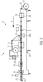
- Fig.1 shows a first embodiment of a packaging system 1.
- the packaging system 1 comprises a packaging machine 2, which in the present embodiment is a tray sealing machine (tray sealer).
- the packaging machine 2 comprises a frame 3, which can carry a supply roll 4 of a lidding film 5.
- the packaging machine 1 also has a feed belt 7, by means of which filled but at this time still unsealed trays 8 can be fed to a sealing station 9 of the packaging machine 2.
- the trays 8 can be transferred into the sealing station 9 by means of a gripper device 10 in a production direction P and there sealed with the lidding film 5 (film) fed from above, for example by sealing the lidding film 5 to the trays 8.
- the sealing station 9 can comprise a sealing tool 11.
- the sealed and thus finished packages can be transferred from the closing station 9 to a discharge belt 12 via the gripper device 10.
- the packaging system 1 has one or more further components, in the present example a conveyor belt 13, a filler 14 and a testing device 15.
- the conveyor belt 13 is used to convey unsealed trays 8 while they are being filled with a product Q.
- a filling device 14 in the vicinity of the conveyor belt 13 is used to pick up the products Q and transfer them into the trays 8.
- the filling device 14 can be configured, for example, as a suction gripper, as a transfer robot or as a (possibly intermittently operating) pouring device.
- a testing device 15 for example a vision system, a metal detector or a check weigher.
- the testing device 15 is used to determine properties of the finished packaging or the products packaged therein.
- a display 27 is arranged on the packaging machine 2. It has control elements 28.
- Fig. 2 shows a second embodiment of a packaging system 1, this time with a packaging machine 2 in the form of a thermoforming packaging machine.
- the thermoforming packaging machine 2 has a forming station 16, a sealing station 17, a cross-cutting device in the form of a film punch 18 and a longitudinal cutting device 19, which are arranged in this order in a production direction R on a machine frame 20.
- On the input side there is a feed roller 21 on the machine frame 20, from which a film web 22 is pulled.
- a material storage device 23 is provided, from which a cover film 5 is pulled.
- a removal device 24 in the form of a conveyor belt is provided on the thermoforming packaging machine 2, with which finished, individual packages 25 are transported away.
- the thermoforming packaging machine 2 also has a feed device that grips the film web 16 and transports it further in the production direction P per main work cycle.
- the feed device can, for example, be designed by clamp chains arranged on both sides.
- the forming station 16 is designed as a deep-drawing station in which troughs 26 are formed in the film web 22 by deep-drawing.
- the forming station 16 can be designed in such a way that several troughs 26 are formed next to one another in the direction perpendicular to the production direction R.
- an insertion section E is provided in which the troughs 26 formed in the film web 16 are filled with products Q by means of a filler 14 provided in addition to the packaging machine 2.
- the cross-cutting device 18 is designed as a film punch which cuts the film web 22 and the cover film 5 in a direction transverse to the production direction P between adjacent troughs 26.
- the film punch 18 works in such a way that the film web 22 is not cut across its entire width, but is not cut at least in one edge area. This enables controlled further transport by the feed device.
- the longitudinal cutting device 19 is designed as a knife arrangement with several rotating circular knives, with which the film web 22 and the cover film 5 are severed between adjacent troughs 26 and at the lateral edge of the film web 22, so that individual packages 25 are present behind the longitudinal cutting device 19.
- the thermoforming packaging machine 2 also has a controller 260. Its task is to control and monitor the processes taking place in the thermoforming packaging machine 2.
- a display 27 with operating elements 28 arranged here on the thermoforming packaging machine 2 serves to visualize or influence the process sequences in the thermoforming packaging machine 2 for or by an operator.
- the packaging system 1 can also have a testing device 15 in addition to the filler, and optionally also other additional components.
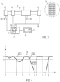
- Fig.3 shows once again schematically the packaging system 1 with the packaging machine 2 and components 13, 14, 15 provided in addition to the packaging machine 2. It is indicated schematically that a sensor 29 is provided on or in the packaging machine 2 and on or in the conveyor belt 13, by means of which at least one parameter of the associated machine 2 or component is monitored.
- the packaging machine 2 and the additional components 13, 14, 15 and the sensors 29 are connected to a computer unit 31 via data and control lines 30.
- the computer unit can be a control computer for the packaging system 1.
- the computer unit has an error analysis section 32 and a memory 33 in which an error source list 34 is stored.
- the error source list 34 also shown in an enlarged view, can include a number of different errors F1, F2, F3, ..., with each error F1, F2, F3 being assigned a specific or most probable error source f1, f2, f3, ... It is entirely conceivable that different errors F1, F2, F4 are assigned the same error source f1.
- An error source f1, f2, f3 can be a specific component 2, 13, 14, 15 of the packaging system 1 or a specific fault within such a component.
- a performance graph 35 can be displayed, which in enlarged form in Fig.4 can be seen.
- the performance graph 35 represents the performance of the packaging system 1 over a certain period of time, namely as performance L (packages per unit of time) over a time axis t.
- performance L packetages per unit of time
- t time axis
- a performance L below a certain performance threshold Ls is considered as underperformance.
- the error analysis section 32 of the packaging system 1 is designed to recognize the time at which underperformance occurs.
- the packaging system 1 starts at time t0 with its nominal power. At time t1, the power L falls below the power threshold Ls for the first time. Up to time t2 , the packaging system 1's power is reduced, only then does the power L rise above the power threshold Ls again.
- the performance of packaging system 1 drops below the performance threshold Ls again until it stops completely at time t 4 .
- Packaging system 1 only starts working again at time t 5 , at its nominal performance L N .
- a sudden stop occurs, ie the performance L is reduced to zero.
- packaging system 1 starts working again; at time t 8 , the performance threshold Ls is exceeded.
- a reduced performance ie a performance L below the threshold Ls, therefore occurs between the times t 1 and t 2 , the times t 3 and t 5 and the times t 6 and t 8 .
- a stop of the packaging system 1 occurs between the times t 4 and t 5 and between the times t 6 and t 7 .
- the error analysis section 32 As soon as the error analysis section 32 has identified a (most probable) reason for the occurrence of a certain stop or reduced performance, ie the error source f1, f2, f3 causing it, the identified error source f1, f2, f3 is shown on the display 27, specifically within the performance graph 35.
- Fig.4 shows an example of how this can be done. Every time a reduced performance or a stop occurs t 1 , t 3 , t 4 is associated with a display of the error source f1, f2, f3 identified as the cause, as shown in Fig.4 indicated. For the sake of clarity, a determined error source for the occurrence of the stop at time t 6 has no longer been shown.
- each stop or each reduced performance determined by the error analysis section 32 can be stored together with an associated time stamp t 1 , t 3 , t 4 , t 6 . Additionally or alternatively, it is possible to record and store the duration of each stop or each reduced performance.
- the packaging system according to the invention or the method according to the invention can be modified in many ways. It is conceivable that the performance graph is updated continuously or intermittently. It is possible for the operator to use a zoom function to enlarge certain time periods or to display longer time periods, i.e. to change the scaling of the time axis t. It is also possible to carry out a statistical evaluation of the errors and error sources determined and to edit the error source list 34, for example via the display 27 or from external devices.
Landscapes
- Engineering & Computer Science (AREA)
- Mechanical Engineering (AREA)
- Physics & Mathematics (AREA)
- General Physics & Mathematics (AREA)
- Automation & Control Theory (AREA)
- Human Computer Interaction (AREA)
- Containers And Plastic Fillers For Packaging (AREA)
- Auxiliary Devices For And Details Of Packaging Control (AREA)
Description
- Die Erfindung bezieht sich auf eine Verpackungsanlage mit den Merkmalen des Oberbegriffs von Anspruch 1 sowie auf ein Verfahren zum Betrieb einer Verpackungsanlage.
- Als Verpackungsanlage wird eine Anlage verstanden, die mindestens eine Verpackungsmaschine aufweist (d.h. eine Maschine, in der Produkte in Verpackungsmaterial verpackt werden) sowie zusätzlich zur Verpackungsmaschine mindestens eine weitere Komponente. Bei dieser weiteren Komponente kann es sich im Kontext der Erfindung um jegliche Maschine oder Station handeln, die auf irgendeine Weise auf die Produkte und/oder auf das Verpackungsmaterial einwirkt. Beispielsweise kann es sich bei der zusätzlichen Komponente um eine Transporteinrichtung zum Transportieren von Produkten handeln, beispielsweise um einen Zuförderer, ein Transportband, einen Umsetz-Roboter, wie beispielsweise einen Delta- oder Scara-Roboter o.ä. Bei der weiteren Komponente kann es sich beispielsweise auch um eine Druckvorrichtung zum Aufbringen eines Drucks auf Verpackungsmaterial, um eine Prüfvorrichtung wie ein Vision-System oder einen Check-Weigher, oder auch um einen Etikettierer handeln. Bei der zusätzlich zur Verpackungsmaschine vorgesehenen Komponente der Verpackungsanlage kann es sich auch um einen Befüller zum Befüllen von Verpackungen mit einem Produkt handeln. Zusätzlich zur mindestens einen Verpackungsmaschine kann die Verpackungsanlage eine oder auch mehrere solcher zusätzlichen Komponenten aufweisen.
- Verpackungsanlagen mit einer Verpackungsmaschine und mindestens einer weiteren Komponente gehen beispielsweise aus der
DE 10 2018 222 397 A1 , derDE 10 2018 214 761 A1 oder derDE 10 2017 124 650 A1 hervor. - Solche Verpackungsanlagen haben typischerweise eine Nennleistung, d.h. eine im störungsfreien Normalbetrieb erreichbare Leistung, d.h. eine Anzahl fertig hergestellter Verpackungen pro Zeiteinheit (beispielsweise pro Minute). Die tatsächliche Leistung der Verpackungsanlage kann Schwankungen unterworfen sein und insbesondere um die Nennleistung herum schwanken. Kritisch wird es, wenn eine Minderleistung auftritt. Im Kontext der Erfindung kann eine "Minderleistung" definiert sein als eine Leistung von beispielsweise 95% oder weniger der Nennleistung, oder von 90% oder weniger der Nennleistung. Ein Spezialfall einer Minderleistung ist ein Stopp der Verpackungsanlage, d.h. eine Reduktion der momentanen Leistung der Verpackungsanlage auf Null. Eine Minderleistung oder gar ein Stopp der Verpackungsanlage kann eine Vielzahl von Ursachen haben.
- Die
WO 2005/031485 A1 offenbart eine Anzeige- und Bedieneinheit für eine Maschine der tabakverarbeitenden Industrie. Wenn ein Maschinenstopp erfolgt, wird dem Bediener in einem Meldungsbereich eines Displays ein Grund für den Maschinenstopp angezeigt. DieEP 2 075 661 A1 beschriebt eine Verpackungslinien-Architektur, bei der eine Leistungsanalyse in Echtzeit erfolgen soll. DieDE 10 2017 007 909 A1 beschreibt eine Produktionssteuerung für Fertigungseinrichtungen, bei der Ursachen für einen Stopp des Produktionssystems erkannt werden sollen. DieDE 10 2018 122 213 A1 beschreibt eine weitere Vorrichtung zur Überwachung und Dokumentation von Fertigungsprozessen, bei denen ein Bediener manuell Fehlerquellen in eine Liste eintragen kann. - Die Aufgabe der vorliegenden Erfindung liegt darin, eine Verpackungsanlage und ein Verfahren zum Betrieb einer Verpackungsanlage dahingehend zu verbessern, dass die mittlere Leistungsfähigkeit der Verpackungsanlage erhöht wird.
- Diese Aufgabe wird gelöst durch eine Verpackungsanlage mit den Merkmalen des Anspruchs 1 bzw. durch ein Verfahren zum Betrieb einer Verpackungsanlage mit den Merkmalen des Anspruchs 7. Vorteilhafte Weiterbildungen der Erfindung sind Gegenstand der abhängigen Ansprüche.
- Erfindungsgemäß ist die Verpackungsanlage dazu konfiguriert, auf dem Display eine Leistungsgrafik darzustellen. Die Leistungsgrafik zeigt, vorzugsweise in Echtzeit, eine aktuelle Leistung der Verpackungsanlage an, vorzugsweise auch den Verlauf der tatsächlich erreichten Leistung über einen bestimmten Zeitraum in die Vergangenheit zurückreichend. Beispielsweise könnte die Leistung in Prozent der Nennleistung dargestellt werden. Zum Ermitteln der Leistung kann z.B. bei intermittierend arbeitenden Verpackungsmaschinen oder Verpackungsanlagen die Anzahl der Takte in einem vorgegebenen Zeitraum herangezogen werden, multipliziert mit der Anzahl der in einem Format bzw. in einem Takt erzeugten Verpackungen.
- Erfindungsgemäß weist die Rechnereinheit der Verpackungsanlage eine Fehleranalysesektion auf, die dazu ausgebildet ist, einen Stopp oder eine Minderleistung der Verpackungsanlage zu erkennen. Wie eingangs dargelegt, kann eine Minderleistung beispielsweise definiert sein als eine Leistung von maximal 95% oder maximal 90% der Nennleistung der Verpackungsanlage. Allgemein kann die Minderleistung als eine tatsächliche Leistung unterhalb einer bestimmten Leistungsschwelle angesehen werden. Ein Stopp der Verpackungsanlage führt zu einer Leistung von Null und somit zu einem Extremfall einer Minderleistung.
- Die Fehleranalysesektion ist dazu ausgebildet, beim Erkennen eines Stopps oder allgemein einer Minderleistung aus einer in einem Speicher gespeicherten Fehlerquellenliste eine für den betreffenden Stopp oder die Minderleistung ursächliche Fehlerquelle zu identifizieren. Die Fehlerquellenliste kann eine beliebige, diskrete Anzahl von potenziellen Fehlerquellen enthalten. Die Fehlerquellenliste kann in Form einer Liste, eines Arrays, einer Tabelle o.ä. gespeichert sein. Sie kann vorzugsweise die häufigsten Fehlerquellen enthalten, die für einen Stopp oder eine Minderleistung ursächlich sein können. Das Identifizieren der ursächlichen Fehlerquelle kann unter Berücksichtigung der Information erfolgen, ob die Verpackungsmaschine oder eine bestimmte andere Komponente der Verpackungsanlage den Stopp oder die Minderleistung verursacht hat, beispielsweise anhand von dort erhaltener Steuer- oder Sensorsignale.
- Schließlich ist die Verpackungsanlage dazu konfiguriert, die ermittelte Fehlerquelle auf dem Display anzuzeigen. Dies erlaubt es dem Bediener der Verpackungsanlage, unmittelbar die Fehlerquelle und die den Fehler verursachende Komponente bzw. Maschine zu identifizieren, ohne länger danach suchen zu müssen. Dies beschleunigt das Beheben des Fehlers und verringert Standzeiten oder Zeiten einer Minderleistung der Verpackungsanlage, was insgesamt die mittlere Leistungsfähigkeit der Verpackungsanlage deutlich erhöht. Die Verpackungsanlage kann auch dazu konfiguriert sein, eine Auswertung oder Statistik von Minderleistungen und ihren Ursachen zu erzeugen. Dies erlaubt es, den Betrieb der Verpackungsanlage weiter zu optimieren, beispielsweise indem systematisch Ursachen für besonders häufige Fehlerquellen identifiziert und diese Ursachen durch Gegenmaßnahmen vermieden werden.
- Zu einem Stopp führende Fehlerquellen können beispielsweise der komplette Ausfall (oder Stromlosigkeit) einer Komponente oder der Verpackungsmaschine sein, oder das Erreichen eines Folienendes (kein Material mehr) einer Unter- oder einer Deckelfolie.
- Nicht zu einem Stopp, aber zu einer Minderleistung führende Fehlerquellen können beispielsweise sein:
- a) Vorwarnung von Etikettenbandende oder Folienende, bevor das Ende erreicht wird
- b) Etikettierer nicht aktiv/bereit, im Fall wenn zwei Etikettierer (redundantes System) bereit stehen müssen, aber nur einer zum Etikettieren in Betrieb ist. (beim Anderen könnte während der Wartezeit die Etikettenrolle erneuert werden)
- c) Warten auf Rückmeldung von Komponenten (z.B. Bereit- oder Fertigsignal fehlt)
- d) Evakuierzeit ist überschritten, die IST-Zeit für das Evakuieren war länger als die SOLL-Zeit
- Im Kontext der Erfindung sind "Meldungen" der Anlage oder ihrer Komponenten als synonym mit "Fehler" zu verstehen, sofern sie sich auf das Melden eines Ereignisses oder eines Zustands beziehen, die zu einem Stopp oder zu einer Minderleistung geführt haben. Die gespeicherte Fehlerquellenliste kann demnach auch eine Liste potentieller Meldungen sein oder umfassen.
- Vorzugsweise ist die Fehleranalysesektion dazu konfiguriert, einen Zeitstempel in Zuordnung zu einem erkannten Stopp oder einer erkannten Minderleistung der Verpackungsanlage zu speichern. Beim Zeitstempel kann es sich um die Uhrzeit (in Stunden, Minuten, ggf. Sekunden), ggf. zuzüglich des Datums, desjenigen Zeitpunkts handeln, zu dem ein Stopp oder eine Minderleistung eingetreten sind oder erkannt wurden. Der Zeitstempel kann auch die Dauer eines Stopps oder einer Minderleistung angeben. Zuordnung bedeutet in diesem Zusammenhang, dass der Zeitstempel einem bestimmten Stopp bzw. einer bestimmten Minderleistung zugeordnet ist.
- Als vorteilhaft für die Handhabung hat es sich herausgestellt, wenn die Leistungsgrafik eine Darstellung einer Leistung der Verpackungsanlage oder der Verpackungsmaschine über einer Zeitachse umfasst. In einer solchen, zweidimensionalen Darstellung kann somit der Verlauf der Leistung über einen gewissen Zeitraum abgelesen werden.
- In einer Variante der Verpackungsanlage ist wenigstens ein Sensor mit der Rechnereinheit verbunden. Der Rechner kann Parameter überwachen und in Form von Sensorsignalen an die Rechnereinheit melden, die Rückschlüsse auf eine Leistung, eine Minderleistung, einen Stopp oder auf den einem Stopp oder einer Minderleistung zugrundeliegenden Fehler erlauben, beispielsweise Temperaturen, elektrische Ströme, elektrische Spannungen, mechanische Spannungen, Drücke etc. Innerhalb der Rechnereinheit kann das vom Sensor erhaltene Signal der Fehleranalysesektion zugeleitet werden.
- Die Verpackungsanlage kann ferner dazu konfiguriert sein, auf dem Display Störungsmeldungen und/oder Warnhinweise anzuzeigen. Dies erleichtert dem Bediener das Erkennen einer Störung.
- In einer Ausführungsform kann das Display an oder in der Verpackungsmaschine angeordnet sein. Dies hat den Vorteil, dass sich der Bediener häufig an der Verpackungsmaschine oder in ihrer Nähe aufhalten wird und das Display hier gut einsehen kann. Alternativ oder zusätzlich kann sich das oder ein weiteres Display allerdings auch entfernt von der Verpackungsmaschine befinden, beispielsweise in einem Bedienraum, in dem das Display über ein Datennetzwerk (drahtgebunden oder drahtlos) oder eine Cloud-Verbindung mit der Verpackungsmaschine und der oder den zusätzlichen Komponenten der Verpackungsanlage verbunden sein kann, oder auf einem mobilen Endgerät.
- Gleiches gilt für die Rechnereinheit oder deren Fehleranalysesektion. Auch die Rechnereinheit und/oder die Fehleranalysesektion können an oder in der Verpackungsmaschine oder an oder in einer der weiteren Komponenten der Verpackungsanlage angeordnet sein. Alternativ können sich die Rechnereinheit und/oder die Fehleranalysesektion (oder Teile davon) auch entfernt von der Verpackungsmaschine befinden, beispielsweise in einem Bedienraum oder auf einem mobilen Endgerät, und über eine drahtgebundene oder drahtlose Datenverbindung in die Verpackungsanlage eingebunden sein.
- Die Erfindung bezieht sich auch auf ein Verfahren zum Betrieb einer Verpackungsanlage, bei dem auf einem Display der Verpackungsanlage eine Leistungsgrafik dargestellt wird, in einem Speicher eine Fehlerquellenliste gespeichert wird, eine Fehleranalysesektion einer Rechnereinheit bei einem Stopp oder einer Minderleistung der Verpackungsanlage aus der Fehlerquellenliste eine für den betreffenden Stopp oder die Minderleistung ursächliche Fehlerquelle identifiziert und die ermittelte Fehlerquelle schließlich auf dem Display angezeigt wird. Damit ergeben sich die eingangs geschilderten Vorteile.
- Zweckmäßig ist es, wenn die Fehlerquellenliste editierbar ist. Insbesondere können auf diese Weise Fehlerquellen konkretisiert und/oder zusätzliche Fehlerquellen zu der Liste hinzugefügt werden. Das Editieren der Fehlerquellenliste kann vorzugsweise vom Display aus erfolgen.
- Vorzugsweise umfasst die Leistungsgrafik eine Darstellung einer Leistung der Verpackungsanlage oder der Verpackungsmaschine über einer Zeitachse, wiederum mit den vorstehend geschilderten Vorteilen.
- Denkbar ist es, dass die Leistungsgrafik kontinuierlich oder taktweise aktualisiert wird. Sofern die Verpackungsmaschine oder die Verpackungsanlage insgesamt intermittierend bzw. taktweise arbeiten, kann das taktweise Aktualisieren der Leistungsgrafik synchronisiert sein mit dem Arbeitstakt der Verpackungsanlage oder -maschine.
- In einer Weiterbildung ist es denkbar, dass in der oder zusammen mit der Leistungsgrafik Rezeptwechsel und/oder Parameterveränderungen auf dem Display angezeigt werden. Dies vergrößert den Informationsumfang, der dem Bediener zur Verfügung gestellt wird, und kann das Auffinden eines Fehlers weiter erleichtern.
- Denkbar ist es ferner, dass ein Zeitpunkt des Eintretens eines Stopps oder einer Minderleistung aufgezeichnet und gespeichert wird, idealerweise in Zuordnung zu einem bestimmten Stopp oder einer Minderleistung. Zusätzlich oder alternativ ist es denkbar, dass ein Zeitraum oder die Dauer eines Stopps oder einer Minderleistung aufgezeichnet und gespeichert werden, erneut idealerweise in Zuordnung zu einem betreffenden Stopp oder einer Minderleistung.
- Bei der Verpackungsmaschine kann es sich beispielsweise um eine Schalenverschließmaschine (Traysealer) oder um eine Tiefziehverpackungsmaschine handeln. Denkbar wäre es auch, dass die Verpackungsmaschine vom Typ einer Kammermaschine oder Kammerbandmaschine ist.
- Im Folgenden werden vorteilhafte Ausführungsformen der Erfindung anhand einer Zeichnung näher erläutert. Im Einzelnen zeigen:
- Fig. 1
- ein Ausführungsbeispiel einer Verpackungsanlage mit einer Schalenverschließmaschine,
- Fig. 2
- ein zweites Ausführungsbeispiel einer Verpackungsanlage mit einer Tiefziehverpackungsmaschine,
- Fig. 3
- eine schematische Darstellung der Verpackungsanlage und
- Fig. 4
- ein Ausführungsbeispiel einer Leistungsgrafik.
- Gleiche Komponenten sind in den Figuren durchgängig mit gleichen oder einander entsprechenden Bezugszeichen versehen.
-
Fig. 1 zeigt ein erstes Ausführungsbeispiel einer Verpackungsanlage 1. Die Verpackungsanlage 1 umfasst eine Verpackungsmaschine 2, bei der es sich im vorliegenden Ausführungsbeispiel um eine Schalenverschließmaschine (Traysealer) handelt. Die Verpackungsmaschine 2 umfasst ein Gestell 3, das eine Vorratsrolle 4 einer Deckelfolie 5 tragen kann. Die Verpackungsmaschine 1 weist ferner ein Zuführband 7 auf, mittels dessen befüllte aber zu diesem Zeitpunkt noch unverschlossene Schalen 8 einer Verschließstation 9 der Verpackungsmaschine 2 zugeführt werden können. Die Schalen 8 können mittels einer Greifereinrichtung 10 in einer Produktionsrichtung P in die Verschließstation 9 umgesetzt werden und dort mit der von oben zugeführten Deckelfolie 5 (Folie) verschlossen werden, beispielsweise durch Ansiegeln der Deckelfolie 5 an die Schalen 8. Zu diesem Zweck kann die Verschließstation 9 ein Siegelwerkzeug 11 umfassen. Die versiegelten und damit fertiggestellten Verpackungen können über die Greifereinrichtung 10 aus der Verschließstation 9 auf ein Abführband 12 umgesetzt werden. - Zusätzlich zu der Verpackungsmaschine 2 weist die Verpackungsanlage 1 eine oder mehrere weitere Komponenten auf, im vorliegenden Beispiel ein Transportband 13, einen Befüller 14 und eine Prüfvorrichtung 15. Das Transportband 13 dient zum Fördern von unverschlossenen Schalen 8 während ihres Befüllens mit einem Produkt Q. Eine Befüllvorrichtung 14 in der Umgebung des Transportbandes 13 dient dazu, die Produkte Q aufzunehmen und in die Schalen 8 umzusetzen. Dazu kann die Befüllvorrichtung 14 beispielsweise als Sauggreifer, als Transfer-Roboter oder auch als (ggf. intermittierend arbeitende) Schüttvorrichtung konfiguriert sein. In Transportrichtung P stromabwärts der Verschließstation 9 befindet sich eine Prüfvorrichtung 15, beispielweise ein Vision-System, ein Metalldetektor oder ein Check-Weigher. Die Prüfvorrichtung 15 dient dazu, Eigenschaften der fertigen Verpackungen oder der darin verpackten Produkte zu ermitteln.
- An der Verpackungsmaschine 2 ist ein Display 27 angeordnet. Es verfügt über Bedienelemente 28.
-
Fig. 2 zeigt ein zweites Ausführungsbeispiel einer Verpackungsanlage 1, diesmal mit einer Verpackungsmaschine 2 in Form einer Tiefziehverpackungsmaschine. Die Tiefziehverpackungsmaschine 2 weist eine Formstation 16, eine Siegelstation 17, eine Querschneideeinrichtung in Form einer Folienstanze 18 und eine Längsschneideeinrichtung 19 auf, die in dieser Reihenfolge in einer Produktionsrichtung R an einem Maschinenrahmen 20 angeordnet sind. Eingangsseitig befindet sich an dem Maschinenrahmen 20 eine Zufuhrrolle 21, von der eine Folienbahn 22 abgezogen wird. Im Bereich der Siegelstation 17 ist ein Materialspeicher 23 vorgesehen, von dem eine Deckelfolie 5 abgezogen wird. Ausgangsseitig ist an der Tiefziehverpackungsmaschine 2 eine Abfuhreinrichtung 24 in Form eines Transportbandes vorgesehen, mit der fertige, vereinzelte Verpackungen 25 abtransportiert werden. Ferner weist die Tiefziehverpackungsmaschine 2 eine Vorschubeinrichtung auf, die die Folienbahn 16 ergreift und diese pro Hauptarbeitstakt in der Produktionsrichtung P weitertransportiert. Die Vorschubeinrichtung kann zum Beispiel durch beidseitig angeordnete Klammerketten ausgeführt sein. - In der dargestellten Ausführungsform ist die Formstation 16 als eine Tiefziehstation ausgebildet, bei der in die Folienbahn 22 durch Tiefziehen Mulden 26 geformt werden. Dabei kann die Formstation 16 derart ausgebildet sein, dass in der Richtung senkrecht zur Produktionsrichtung R mehrere Mulden 26 nebeneinander gebildet werden. In Produktionsrichtung P hinter der Formstation 16 ist eine Einlegestrecke E vorgesehen, in der die in der Folienbahn 16 geformten Mulden 26 mittels eines zusätzlich zur Verpackungsmaschine 2 vorgesehenen Befüllers 14 mit Produkten Q befüllt werden.
- Die Querschneideeinrichtung 18 ist als Folienstanze ausgebildet, die die Folienbahn 22 und die Deckelfolie 5 in einer Richtung quer zur Produktionsrichtung P zwischen benachbarten Mulden 26 durchtrennt. Dabei arbeitet die Folienstanze 18 derart, dass die Folienbahn 22 nicht über die gesamte Breite aufgetrennt wird, sondern zumindest in einem Randbereich nicht durchtrennt wird. Dies ermöglicht einen kontrollierten Weitertransport durch die Vorschubeinrichtung.
- Die Längsschneideeinrichtung 19 ist in der dargestellten Ausführungsform als eine Messeranordnung mit mehreren rotierenden Rundmessern ausgebildet, mit der die Folienbahn 22 und die Deckelfolie 5 zwischen benachbarten Mulden 26 und am seitlichen Rand der Folienbahn 22 durchtrennt werden, so dass hinter der Längsschneideeinrichtung 19 vereinzelte Verpackungen 25 vorliegen.
- Die Tiefziehverpackungsmaschine 2 verfügt ferner über eine Steuerung 260. Sie hat die Aufgabe, die in der Tiefziehverpackungsmaschine 2 ablaufenden Prozesse zu steuern und zu überwachen. Ein hier an der Tiefziehverpackungsmaschine 2 angeordnetes Display 27 mit Bedienelementen 28 dient zum Visualisieren bzw. Beeinflussen der Prozessabläufe in der Tiefziehverpackungsmaschine 2 für bzw. durch einen Bediener.
- Zusätzlich zur Verpackungsmaschine 2 kann die Verpackungsanlage 1 neben dem Befüller auch eine Prüfvorrichtung 15 aufweisen, optional auch weitere zusätzliche Komponenten.
-
Fig. 3 zeigt noch einmal schematisch die Verpackungsanlage 1 mit der Verpackungsmaschine 2 und zusätzlich zur Verpackungsmaschine 2 vorgesehenen Komponenten 13, 14, 15. Schematisch ist angedeutet, dass an oder in der Verpackungsmaschine 2 sowie an oder in dem Transportband 13 jeweils ein Sensor 29 vorgesehen ist, mittels dessen wenigstens ein Parameter der zugehörigen Maschine 2 oder Komponente überwacht wird. - Über Daten- und Steuerleitungen 30 sind die Verpackungsmaschine 2 sowie die zusätzlichen Komponenten 13, 14, 15 und die Sensoren 29 verbunden mit einer Rechnereinheit 31. Bei der Rechnereinheit kann es sich um einen Steuercomputer für die Verpackungsanlage 1 handeln. Die Rechnereinheit weist eine Fehleranalysesektion 32 sowie einen Speicher 33 auf, in dem eine Fehlerquellenliste 34 gespeichert ist. Die auch in einer Vergrößerung gezeigte Fehlerquellenliste 34 kann eine Anzahl verschiedener Fehler F1, F2, F3, ... umfassen, wobei jedem Fehler F1, F2, F3 eine bestimmte oder eine wahrscheinlichste Fehlerquelle f1, f2, f3, ... zugeordnet ist. Es ist durchaus denkbar, dass verschiedenen Fehlern F1, F2, F4 dieselbe Fehlerquelle f1 zugeordnet ist. Bei einer Fehlerquelle f1, f2, f3 kann es sich um eine bestimmte Komponente 2, 13, 14, 15 der Verpackungsanlage 1 oder aber um eine bestimmte Störung innerhalb einer solchen Komponente handeln.
- Auf dem mit der Rechnereinheit 31 verbundenen Display 27 der Verpackungsanlage 1 ist eine Leistungsgrafik 35 darstellbar, die in vergrößerter Form in
Fig. 4 zu sehen ist. Die Leistungsgrafik 35 stellt eine Leistung der Verpackungsanlage 1 über einen bestimmten Zeitraum dar, und zwar als Leistung L (Verpackungen pro Zeiteinheit) über einer Zeitachse t. Wie eingangs erläutert, verfügt die Verpackungsanlage 1 über eine Nennleistung LN, die sie im störungsfreien Normalbetrieb erreichen kann oder erreichen soll. Abhängig von verschiedenen Faktoren kann die tatsächlich erreichte Leistung L(t) schwanken, wie inFig. 4 dargestellt. - Eine Leistung L unterhalb einer bestimmten Leistungsschwelle Ls wird als Minderleistung aufgefasst. Die Fehleranalysesektion 32 der Verpackungsanlage 1 ist dazu ausgebildet, den Zeitpunkt des Eintretens einer Minderleistung zu erkennen.
- Im Beispiel gemäß
Fig. 4 startet die Verpackungsanlage 1 zum Zeitpunkt to mit ihrer Nennleistung. Beim Zeitpunkt t1 sinkt die Leistung L erstmalig unter die Leistungsschwelle Ls. Bis zum Zeitpunkt t2 besteht eine Minderleistung der Verpackungsanlage 1, erst danach steigt die Leistung L wieder über die Leistungsschwelle Ls. - Zum Zeitpunkt t3 sinkt die Leistung der Verpackungsanlage 1 erneut unter die Leistungsschwelle Ls bis zu einem vollständigen Stopp am Zeitpunkt t4. Erst zum Zeitpunkt t5 arbeitet die Verpackungsanlage 1 wieder, und zwar mit ihrer Nennleistung LN. Zum Zeitpunkt t6 tritt ein schlagartiger Stopp auf, d.h. die Leistung L reduziert sich auf Null. Zum Zeitpunkt t7 beginnt die Verpackungsanlage 1 wieder zu arbeiten; zum Zeitpunkt t8 wird die Leistungsschwelle Ls überschritten.
- Eine Minderleistung, d.h. eine Leistung L unterhalb der Schwelle Ls tritt somit zwischen den Zeitpunkten t1 und t2, den Zeitpunkten t3 und t5 und den Zeitpunkten t6 und t8 auf. Ein Stopp der Verpackungsanlage 1 liegt zwischen den Zeitpunkten t4 und t5 sowie zwischen den Zeitpunkten t6 und t7 vor.
- Sobald die Fehleranalysesektion 32 einen (wahrscheinlichsten) Grund für den Eintritt eines bestimmten Stopps oder einer Minderleistung erkannt hat, d.h. die dafür ursächliche Fehlerquelle f1, f2, f3, wird die ermittelte Fehlerquelle f1, f2, f3 auf dem Display 27 angezeigt, und zwar innerhalb der Leistungsgrafik 35.
Fig. 4 zeigt exemplarisch, wie dies erfolgen kann. Jeder Zeitpunkt des Eintritts einer Minderleistung oder eines Stopps t1, t3, t4 ist mit einer Anzeige der dafür als ursächlich erkannten Fehlerquelle f1, f2, f3 verbunden, wie inFig. 4 angedeutet. Der Übersichtlichkeit halber wurde eine ermittelte Fehlerquelle für den Eintritt des Stopps zum Zeitpunkt t6 nicht mehr dargestellt. Innerhalb des Speichers 33 kann jeder von der Fehleranalysesektion 32 ermittelte Stopp bzw. jede Minderleistung zusammen mit einem zugeordneten Zeitstempel t1, t3, t4, t6 gespeichert werden. Zusätzlich oder alternativ besteht die Möglichkeit, die Zeitdauer jedes Stopps bzw. jeder Minderleistung aufzuzeichnen und zu speichern. - Die erfindungsgemäße Verpackungsanlage bzw. das erfindungsgemäße Verfahren können in vielfacher Weise verändert werden. Denkbar ist es, dass die Leistungsgrafik kontinuierlich oder taktweise aktualisiert wird. Es besteht die Möglichkeit, dass der Bediener mittels einer Zoom-Funktion bestimmte Zeiträume vergrößert darstellt oder aber größere Zeiträume darstellt, d.h. die Skalierung der Zeitachse t verändert. Es besteht auch die Möglichkeit für eine statistische Auswertung der ermittelten Fehler und Fehlerquellen sowie für ein Editieren der Fehlerquellenliste 34, beispielsweise über das Display 27 oder von externen Geräten aus.
Claims (12)
- Verpackungsanlage (1) mit einer Verpackungsmaschine (2) und mindestens einer zusätzlich zur Verpackungsmaschine (2) vorgesehenen Komponente (13, 14, 15), wobei die Verpackungsanlage (1) ferner ein Display (27) und eine Rechnereinheit (31) aufweist,wobei die Verpackungsanlage (1) dazu konfiguriert ist, auf dem Display (27) eine Leistungsgrafik (35) darzustellen, und die Rechnereinheit (31) eine Fehleranalysesektion (32) aufweist, die dazu ausgebildet ist, einen Stopp oder eine Minderleistung der Verpackungsanlage (1) zu erkennen,dadurch gekennzeichnet, dassdie Fehleranalysesektion dazu ausgebildet ist, bei Erkennen eines Stopps oder einer Minderleistung aus einer in einem Speicher (33) gespeicherten Fehlerquellenliste (34) eine für den Stopp oder die Minderleistung ursächliche Fehlerquelle (f1, f2, f3) zu identifizieren,wobei die Verpackungsanlage (1) ferner dazu konfiguriert ist, die ermittelte Fehlerquelle (f1, f2, f3) innerhalb der Leistungsgrafik (53) auf dem Display (27) anzuzeigen, wobei jeder Zeitpunkt des Eintritts einer Minderleistung oder eines Stopps (t1, t3, t4) mit einer Anzeige der dafür als ursächlich erkannten Fehlerquelle (f1, f2, f3) verbunden ist.
- Verpackungsanlage nach Anspruch 1, dadurch gekennzeichnet, dass die Fehleranalysesektion (32) dazu konfiguriert ist, einen Zeitstempel (t1, t3, t4) in Zuordnung zu einem erkannten Stopp oder einer erkannten Minderleistung der Verpackungsanlage (1) zu speichern.
- Verpackungsanlage nach einem der vorangehenden Ansprüche, dadurch gekennzeichnet, dass die Leistungsgrafik (35) eine Darstellung einer Leistung der Verpackungsanlage (1) oder der Verpackungsmaschine (2) über einer Zeitachse (t) umfasst.
- Verpackungsanlage nach einem der vorangehenden Ansprüche, dadurch gekennzeichnet, dass wenigstens ein Sensor (29) mit der Rechnereinheit (31) verbunden ist.
- Verpackungsanlage nach einem der vorangehenden Ansprüche, dadurch gekennzeichnet, dass die Verpackungsanlage (1) dazu konfiguriert ist, auf dem Display (27) Störungsmeldungen und/oder Warnhinweise anzuzeigen.
- Verpackungsanlage nach einem der vorangehenden Ansprüche, dadurch gekennzeichnet, dass das Display (27) an oder in der Verpackungsmaschine (2) angeordnet ist.
- Verfahren zum Betrieb einer Verpackungsanlage (1) mit einer Verpackungsmaschine (2) und mindestens einer zusätzlich zur Verpackungsmaschine (2) vorgesehenen Komponente (13, 14 ,15), wobei die Verpackungsanlage (1) ferner ein Display (27) und eine Rechnereinheit (31) aufweist,wobei auf dem Display (27) eine Leistungsgrafik (35) dargestellt wird,wobei die Rechnereinheit (31) eine Fehleranalysesektion (32) aufweist,dadurch gekennzeichnet, dass in einem Speicher (33) eine Fehlerquellenliste (34) gespeichert wird,dass die Fehleranalysesektion (32) bei einem Stopp oder einer Minderleistung der Verpackungsanlage (1) aus der Fehlerquellenliste (34) eine für den Stopp oder die Minderleistung ursächliche Fehlerquelle (f1, f2, f3) identifiziert,und dass die ermittelte Fehlerquelle (f1, f2, f3) innerhalb der Leistungsgrafik (35) auf dem Display (27) angezeigt wird, wobei jeder Zeitpunkt des Eintritts einer Minderleistung oder eines Stopps (t1, t3, t4) mit einer Anzeige der dafür als ursächlich erkannten Fehlerquelle (f1, f2, f3) verbunden ist.
- Verfahren nach Anspruch 7, dadurch gekennzeichnet, dass die Fehlerquellenliste (34) editierbar ist.
- Verfahren nach einem der Ansprüche 7 oder 8, dadurch gekennzeichnet, dass die Leistungsgrafik (35) eine Darstellung einer Leistung der Verpackungsanlage (1) oder der Verpackungsmaschine (3) über einer Zeitachse (t) umfasst.
- Verfahren nach einem der Ansprüche 7 bis 9, dadurch gekennzeichnet, dass die Leistungsgrafik (35) kontinuierlich oder taktweise aktualisiert wird.
- Verfahren nach einem der Ansprüche 7 bis 10, dadurch gekennzeichnet, dass in der oder zusammen mit der Leistungsgrafik (35) Rezeptwechsel und/oder Parameterveränderungen angezeigt werden.
- Verfahren nach einem der Ansprüche 7 bis 11, dadurch gekennzeichnet, dass ein Zeitpunkt des Eintretens eines Stopps oder einer Minderleistung und/oder ein Zeitraum oder die Dauer eines Stopps oder einer Minderleistung aufgezeichnet und gespeichert werden.
Applications Claiming Priority (1)
| Application Number | Priority Date | Filing Date | Title |
|---|---|---|---|
| DE102021107878.4A DE102021107878A1 (de) | 2021-03-29 | 2021-03-29 | Verpackungsanlage und verfahren mit fehleranalyse |
Publications (2)
| Publication Number | Publication Date |
|---|---|
| EP4068030A1 EP4068030A1 (de) | 2022-10-05 |
| EP4068030B1 true EP4068030B1 (de) | 2024-09-11 |
Family
ID=80953572
Family Applications (1)
| Application Number | Title | Priority Date | Filing Date |
|---|---|---|---|
| EP22164610.2A Active EP4068030B1 (de) | 2021-03-29 | 2022-03-28 | Verpackungsanlage und verfahren mit fehleranalyse |
Country Status (4)
| Country | Link |
|---|---|
| US (1) | US20220306330A1 (de) |
| EP (1) | EP4068030B1 (de) |
| DE (1) | DE102021107878A1 (de) |
| ES (1) | ES2992995T3 (de) |
Families Citing this family (1)
| Publication number | Priority date | Publication date | Assignee | Title |
|---|---|---|---|---|
| DE102024106635A1 (de) * | 2024-03-07 | 2025-09-11 | Focke & Co. (Gmbh & Co. Kg) | Verfahren und Vorrichtung zur Ermittlung von Packungsfehlern |
Citations (9)
| Publication number | Priority date | Publication date | Assignee | Title |
|---|---|---|---|---|
| WO2005031485A1 (de) | 2003-08-30 | 2005-04-07 | Hauni Maschinenbau Ag | Anzeige- und bedieneinheit für eine maschine der tabakverarbeitenden industrie |
| US7023440B1 (en) | 1998-09-14 | 2006-04-04 | Fisher Rosemount Systems, Inc. | Methods and apparatus for integrated display of process events and trend data |
| US20090085917A1 (en) | 2007-09-28 | 2009-04-02 | Bruce Gordon Fuller | Variable and event association on a display |
| EP2075661A1 (de) | 2007-12-31 | 2009-07-01 | Tetra Laval Holdings & Finance SA | Integrierte Verpackungssystemarchitektur |
| WO2013144131A1 (de) | 2012-03-26 | 2013-10-03 | Gea Cfs Germany Gmbh | Verfahren zur überprüfung der verfügbarkeit der komponenten einer produktions- und/oder verpackungslinie |
| DE102017007909A1 (de) | 2016-08-29 | 2018-03-01 | Fanuc Corporation | Produktionssteuerung, ausgestattet mit einer Funktion zur Identifizierung der Ursache nach einem Betriebsstop einer Produktionseinrichtung, die Fertigungseinrichtungen umfasst |
| DE102018122213A1 (de) | 2017-10-09 | 2019-04-11 | Hubert Plattmann | Vorrichtung zur Überwachung und Dokumentation von Fertigungsprozessen |
| JP2020013297A (ja) | 2018-07-18 | 2020-01-23 | 凸版印刷株式会社 | 充填シールシステムおよび情報処理装置 |
| CN112513761A (zh) | 2019-03-13 | 2021-03-16 | 欧姆龙株式会社 | 显示系统 |
Family Cites Families (10)
| Publication number | Priority date | Publication date | Assignee | Title |
|---|---|---|---|---|
| US4722168A (en) * | 1987-06-25 | 1988-02-02 | Doboy Packaging Machinery, Inc. | Product-out-of-registration control for high speed wrapping machine |
| US6524230B1 (en) * | 1994-07-22 | 2003-02-25 | Ranpak Corp. | Packing material product and method and apparatus for making, monitoring and controlling the same |
| DE102011119584A1 (de) | 2011-10-05 | 2013-04-11 | Focke & Co. (Gmbh & Co. Kg) | System zum Betreiben einer Verpackungsanlage |
| EP2749500B1 (de) * | 2012-12-27 | 2015-02-11 | Multivac Sepp Haggenmüller GmbH & Co. KG | Schalenverschließmaschine mit Überwachungsvorrichtung und Verfahren |
| DE102015016228A1 (de) | 2015-12-16 | 2017-06-22 | Focke & Co. (Gmbh & Co. Kg) | Verfahren zum Betreiben einer Verpackungsanlage für Tabakartikel |
| DE102017124650A1 (de) | 2017-10-23 | 2019-04-25 | Multivac Sepp Haggenmüller Se & Co. Kg | Verpackungsanlage und Verfahren zum Verpacken von in Einzelportionen zerlegten Produkten |
| DE102018214761A1 (de) | 2018-08-30 | 2020-03-05 | Multivac Sepp Haggenmüller Se & Co. Kg | Verpackungsanlage und verfahren zum herstellen einer verpackung |
| DE102018222397A1 (de) | 2018-12-20 | 2020-06-25 | Multivac Sepp Haggenmüller Se & Co. Kg | Verpackungsanlage mit Untergreifer |
| AU2020241849B2 (en) * | 2019-03-20 | 2023-03-16 | Lantech.Com, Llc | Packaging material evaluation and apparatus therefor for evaluating simulated flaws |
| US11181872B1 (en) * | 2019-05-30 | 2021-11-23 | Georgia-Pacific LLC | Systems and processes for optimizing operation of industrial equipment |
-
2021
- 2021-03-29 DE DE102021107878.4A patent/DE102021107878A1/de active Pending
-
2022
- 2022-03-28 ES ES22164610T patent/ES2992995T3/es active Active
- 2022-03-28 EP EP22164610.2A patent/EP4068030B1/de active Active
- 2022-03-29 US US17/707,224 patent/US20220306330A1/en not_active Abandoned
Patent Citations (10)
| Publication number | Priority date | Publication date | Assignee | Title |
|---|---|---|---|---|
| US7023440B1 (en) | 1998-09-14 | 2006-04-04 | Fisher Rosemount Systems, Inc. | Methods and apparatus for integrated display of process events and trend data |
| WO2005031485A1 (de) | 2003-08-30 | 2005-04-07 | Hauni Maschinenbau Ag | Anzeige- und bedieneinheit für eine maschine der tabakverarbeitenden industrie |
| US20090085917A1 (en) | 2007-09-28 | 2009-04-02 | Bruce Gordon Fuller | Variable and event association on a display |
| EP2075661A1 (de) | 2007-12-31 | 2009-07-01 | Tetra Laval Holdings & Finance SA | Integrierte Verpackungssystemarchitektur |
| WO2013144131A1 (de) | 2012-03-26 | 2013-10-03 | Gea Cfs Germany Gmbh | Verfahren zur überprüfung der verfügbarkeit der komponenten einer produktions- und/oder verpackungslinie |
| DE102017007909A1 (de) | 2016-08-29 | 2018-03-01 | Fanuc Corporation | Produktionssteuerung, ausgestattet mit einer Funktion zur Identifizierung der Ursache nach einem Betriebsstop einer Produktionseinrichtung, die Fertigungseinrichtungen umfasst |
| DE102018122213A1 (de) | 2017-10-09 | 2019-04-11 | Hubert Plattmann | Vorrichtung zur Überwachung und Dokumentation von Fertigungsprozessen |
| JP2020013297A (ja) | 2018-07-18 | 2020-01-23 | 凸版印刷株式会社 | 充填シールシステムおよび情報処理装置 |
| CN112513761A (zh) | 2019-03-13 | 2021-03-16 | 欧姆龙株式会社 | 显示系统 |
| EP3940490A1 (de) | 2019-03-13 | 2022-01-19 | OMRON Corporation | Anzeigesystem |
Non-Patent Citations (9)
| Title |
|---|
| ANONYMOUS: "Betriebsanleitung Touch Screen WPC Weber Power Control ", WEBER - DE, 1 January 2016 (2016-01-01), pages 1 - 69, XP093287431 |
| ANONYMOUS: "Betriebsanleitung Touch-Screen WPC Weber Power Control", WEBER - DE, 1 January 2017 (2017-01-01), pages 1 - 73, XP093287437 |
| ANONYMOUS: "Betriebsanleitung Touch-Screen WPC Weber Power Control", WEBER - DE, 1 January 2020 (2020-01-01), pages 1 - 83, XP093287439 |
| ANONYMOUS: "Operating manual Touch-Screen WPC Weber Power Control ", WEBER - EN, 1 January 2016 (2016-01-01), pages 1 - 69, XP093287436 |
| D10a - MTeM 2019 Final Program |
| D11a - S-Food Co., Ltd., Document No: 5110001567 |
| D11b - S-Food Co., Ltd., Document No: 5110001568 |
| D8a - Maschinenübersetzung D8 |
| HÖRMANN BERND OTTO, BIZUBAC DAN, POPA MARCEL SABIN: "Industrial Intelligent Software Applications of the Overall Equipment Effectiveness (OEE) in Manufacturing", MATEC WEB OF CONFERENCES, vol. 299, 1 January 2019 (2019-01-01), pages 1 - 6, XP093287428, ISSN: 2261-236X, DOI: 10.1051/matecconf/201929905011 |
Also Published As
| Publication number | Publication date |
|---|---|
| EP4068030A1 (de) | 2022-10-05 |
| DE102021107878A1 (de) | 2022-09-29 |
| US20220306330A1 (en) | 2022-09-29 |
| ES2992995T3 (en) | 2024-12-20 |
Similar Documents
| Publication | Publication Date | Title |
|---|---|---|
| EP2760748B1 (de) | Integrierte qualitätskontrolle von verbrauchsmaterialien für verpackungsmaschinen | |
| EP2551203B1 (de) | Verfahren zum Schneiden von Packungen | |
| EP1598276B1 (de) | Verpackungsmaschine und Verfahren zum Schneiden von Packungen | |
| DE102011010601B4 (de) | Verpackungsmaschine zum Herstellen einer Mehrlagenpackung | |
| EP3488675B1 (de) | Vorrichtung zum aufbringen von datenträgern auf eine trägerbahn | |
| DE60306231T2 (de) | Verfahren zur Verwaltung der Versorgung mit Hüll- und/oder zusätzlichem und/oder Hilfsmaterial in einem System zur Herstellung von Tabakwaren | |
| DE102010034676A1 (de) | Fördern von Gegenständen | |
| EP4068030A1 (de) | Verpackungsanlage und verfahren mit fehleranalyse | |
| EP3521185A1 (de) | Verfahren zum steuern des vorschubs einer folienbahn in einer verpackungsmaschine | |
| DE102007016426A1 (de) | Verfahren und Vorrichtung zum Aufbringen von Etiketten auf Gegenstände | |
| DE102016200540A1 (de) | Vorrichtung und Verfahren zum Gruppieren und Zusammenfassen von Artikeln zu mehreren Gebinden mit unterschiedlichen Gebindegrößen | |
| WO2019081388A1 (de) | Verpackungsanlage und verfahren zum verpacken von in einzelportionen zerlegten produkten | |
| EP4234418A1 (de) | Verpackungsmaschine oder verpackungslinie mit dynamischem rezeptwechsel | |
| EP3284588B1 (de) | Vorrichtung und verfahren zum herstellen von füllmaterial | |
| DE102013013077A1 (de) | Vorrichtung und Verfahren zum Etikettieren | |
| EP3088315A1 (de) | Tiefziehverpackungsmaschine mit streifenstanze | |
| DE102021110638A1 (de) | Verfahren zum Etikettieren und/oder Bedrucken einer Abfolge von hintereinander angeordneten Verpackungsformaten | |
| EP4336289B1 (de) | Verpackungsanlage und verfahren zur steuerung einer solchen verpackungsanlage | |
| EP1872099B1 (de) | Wiegevorrichtung und -verfahren | |
| EP3278943A1 (de) | Tiefziehmaschine mit rotationsschneidvorrichtung | |
| EP1872098B1 (de) | Verpackungsmaschine | |
| EP3070013B1 (de) | Codiervorrichtung zum codieren von gebindepackungen, verfahren zum codieren einer gebindepackung und etikettiersystem mit einer codiervorrichtung | |
| DE102020005089A1 (de) | Verpackungsmaschine zum Verpacken von pharmazeutischen Produkten in Blisterpackungen | |
| EP4336285B1 (de) | Lebensmittelverarbeitungsmaschine und verfahren zum einschränken von durch einen bediener an einer lebensmittelverarbeitungsmaschine aktivierbaren prozessen | |
| EP4202583B1 (de) | Produktionslinie zum herstellen verpackter produkte mit vorausschauender erfassung einer erforderlichen bedienerinteraktion |
Legal Events
| Date | Code | Title | Description |
|---|---|---|---|
| PUAI | Public reference made under article 153(3) epc to a published international application that has entered the european phase |
Free format text: ORIGINAL CODE: 0009012 |
|
| STAA | Information on the status of an ep patent application or granted ep patent |
Free format text: STATUS: THE APPLICATION HAS BEEN PUBLISHED |
|
| AK | Designated contracting states |
Kind code of ref document: A1 Designated state(s): AL AT BE BG CH CY CZ DE DK EE ES FI FR GB GR HR HU IE IS IT LI LT LU LV MC MK MT NL NO PL PT RO RS SE SI SK SM TR |
|
| STAA | Information on the status of an ep patent application or granted ep patent |
Free format text: STATUS: REQUEST FOR EXAMINATION WAS MADE |
|
| 17P | Request for examination filed |
Effective date: 20230306 |
|
| RBV | Designated contracting states (corrected) |
Designated state(s): AL AT BE BG CH CY CZ DE DK EE ES FI FR GB GR HR HU IE IS IT LI LT LU LV MC MK MT NL NO PL PT RO RS SE SI SK SM TR |
|
| P01 | Opt-out of the competence of the unified patent court (upc) registered |
Effective date: 20230801 |
|
| GRAP | Despatch of communication of intention to grant a patent |
Free format text: ORIGINAL CODE: EPIDOSNIGR1 |
|
| STAA | Information on the status of an ep patent application or granted ep patent |
Free format text: STATUS: GRANT OF PATENT IS INTENDED |
|
| INTG | Intention to grant announced |
Effective date: 20240425 |
|
| GRAS | Grant fee paid |
Free format text: ORIGINAL CODE: EPIDOSNIGR3 |
|
| GRAA | (expected) grant |
Free format text: ORIGINAL CODE: 0009210 |
|
| STAA | Information on the status of an ep patent application or granted ep patent |
Free format text: STATUS: THE PATENT HAS BEEN GRANTED |
|
| AK | Designated contracting states |
Kind code of ref document: B1 Designated state(s): AL AT BE BG CH CY CZ DE DK EE ES FI FR GB GR HR HU IE IS IT LI LT LU LV MC MK MT NL NO PL PT RO RS SE SI SK SM TR |
|
| REG | Reference to a national code |
Ref country code: GB Ref legal event code: FG4D Free format text: NOT ENGLISH |
|
| REG | Reference to a national code |
Ref country code: CH Ref legal event code: EP |
|
| REG | Reference to a national code |
Ref country code: DE Ref legal event code: R096 Ref document number: 502022001632 Country of ref document: DE |
|
| REG | Reference to a national code |
Ref country code: IE Ref legal event code: FG4D Free format text: LANGUAGE OF EP DOCUMENT: GERMAN |
|
| REG | Reference to a national code |
Ref country code: ES Ref legal event code: FG2A Ref document number: 2992995 Country of ref document: ES Kind code of ref document: T3 Effective date: 20241220 |
|
| REG | Reference to a national code |
Ref country code: LT Ref legal event code: MG9D |
|
| PG25 | Lapsed in a contracting state [announced via postgrant information from national office to epo] |
Ref country code: NO Free format text: LAPSE BECAUSE OF FAILURE TO SUBMIT A TRANSLATION OF THE DESCRIPTION OR TO PAY THE FEE WITHIN THE PRESCRIBED TIME-LIMIT Effective date: 20241211 |
|
| REG | Reference to a national code |
Ref country code: NL Ref legal event code: MP Effective date: 20240911 |
|
| PG25 | Lapsed in a contracting state [announced via postgrant information from national office to epo] |
Ref country code: GR Free format text: LAPSE BECAUSE OF FAILURE TO SUBMIT A TRANSLATION OF THE DESCRIPTION OR TO PAY THE FEE WITHIN THE PRESCRIBED TIME-LIMIT Effective date: 20241212 Ref country code: FI Free format text: LAPSE BECAUSE OF FAILURE TO SUBMIT A TRANSLATION OF THE DESCRIPTION OR TO PAY THE FEE WITHIN THE PRESCRIBED TIME-LIMIT Effective date: 20240911 |
|
| PG25 | Lapsed in a contracting state [announced via postgrant information from national office to epo] |
Ref country code: BG Free format text: LAPSE BECAUSE OF FAILURE TO SUBMIT A TRANSLATION OF THE DESCRIPTION OR TO PAY THE FEE WITHIN THE PRESCRIBED TIME-LIMIT Effective date: 20240911 |
|
| PG25 | Lapsed in a contracting state [announced via postgrant information from national office to epo] |
Ref country code: LV Free format text: LAPSE BECAUSE OF FAILURE TO SUBMIT A TRANSLATION OF THE DESCRIPTION OR TO PAY THE FEE WITHIN THE PRESCRIBED TIME-LIMIT Effective date: 20240911 |
|
| PG25 | Lapsed in a contracting state [announced via postgrant information from national office to epo] |
Ref country code: HR Free format text: LAPSE BECAUSE OF FAILURE TO SUBMIT A TRANSLATION OF THE DESCRIPTION OR TO PAY THE FEE WITHIN THE PRESCRIBED TIME-LIMIT Effective date: 20240911 |
|
| PG25 | Lapsed in a contracting state [announced via postgrant information from national office to epo] |
Ref country code: RS Free format text: LAPSE BECAUSE OF FAILURE TO SUBMIT A TRANSLATION OF THE DESCRIPTION OR TO PAY THE FEE WITHIN THE PRESCRIBED TIME-LIMIT Effective date: 20241211 |
|
| PG25 | Lapsed in a contracting state [announced via postgrant information from national office to epo] |
Ref country code: RS Free format text: LAPSE BECAUSE OF FAILURE TO SUBMIT A TRANSLATION OF THE DESCRIPTION OR TO PAY THE FEE WITHIN THE PRESCRIBED TIME-LIMIT Effective date: 20241211 Ref country code: NO Free format text: LAPSE BECAUSE OF FAILURE TO SUBMIT A TRANSLATION OF THE DESCRIPTION OR TO PAY THE FEE WITHIN THE PRESCRIBED TIME-LIMIT Effective date: 20241211 Ref country code: LV Free format text: LAPSE BECAUSE OF FAILURE TO SUBMIT A TRANSLATION OF THE DESCRIPTION OR TO PAY THE FEE WITHIN THE PRESCRIBED TIME-LIMIT Effective date: 20240911 Ref country code: HR Free format text: LAPSE BECAUSE OF FAILURE TO SUBMIT A TRANSLATION OF THE DESCRIPTION OR TO PAY THE FEE WITHIN THE PRESCRIBED TIME-LIMIT Effective date: 20240911 Ref country code: GR Free format text: LAPSE BECAUSE OF FAILURE TO SUBMIT A TRANSLATION OF THE DESCRIPTION OR TO PAY THE FEE WITHIN THE PRESCRIBED TIME-LIMIT Effective date: 20241212 Ref country code: FI Free format text: LAPSE BECAUSE OF FAILURE TO SUBMIT A TRANSLATION OF THE DESCRIPTION OR TO PAY THE FEE WITHIN THE PRESCRIBED TIME-LIMIT Effective date: 20240911 Ref country code: BG Free format text: LAPSE BECAUSE OF FAILURE TO SUBMIT A TRANSLATION OF THE DESCRIPTION OR TO PAY THE FEE WITHIN THE PRESCRIBED TIME-LIMIT Effective date: 20240911 |
|
| PG25 | Lapsed in a contracting state [announced via postgrant information from national office to epo] |
Ref country code: NL Free format text: LAPSE BECAUSE OF FAILURE TO SUBMIT A TRANSLATION OF THE DESCRIPTION OR TO PAY THE FEE WITHIN THE PRESCRIBED TIME-LIMIT Effective date: 20240911 |
|
| PG25 | Lapsed in a contracting state [announced via postgrant information from national office to epo] |
Ref country code: IS Free format text: LAPSE BECAUSE OF FAILURE TO SUBMIT A TRANSLATION OF THE DESCRIPTION OR TO PAY THE FEE WITHIN THE PRESCRIBED TIME-LIMIT Effective date: 20250111 Ref country code: PT Free format text: LAPSE BECAUSE OF FAILURE TO SUBMIT A TRANSLATION OF THE DESCRIPTION OR TO PAY THE FEE WITHIN THE PRESCRIBED TIME-LIMIT Effective date: 20250113 |
|
| PG25 | Lapsed in a contracting state [announced via postgrant information from national office to epo] |
Ref country code: SM Free format text: LAPSE BECAUSE OF FAILURE TO SUBMIT A TRANSLATION OF THE DESCRIPTION OR TO PAY THE FEE WITHIN THE PRESCRIBED TIME-LIMIT Effective date: 20240911 Ref country code: RO Free format text: LAPSE BECAUSE OF FAILURE TO SUBMIT A TRANSLATION OF THE DESCRIPTION OR TO PAY THE FEE WITHIN THE PRESCRIBED TIME-LIMIT Effective date: 20240911 |
|
| PG25 | Lapsed in a contracting state [announced via postgrant information from national office to epo] |
Ref country code: EE Free format text: LAPSE BECAUSE OF FAILURE TO SUBMIT A TRANSLATION OF THE DESCRIPTION OR TO PAY THE FEE WITHIN THE PRESCRIBED TIME-LIMIT Effective date: 20240911 |
|
| PG25 | Lapsed in a contracting state [announced via postgrant information from national office to epo] |
Ref country code: PL Free format text: LAPSE BECAUSE OF FAILURE TO SUBMIT A TRANSLATION OF THE DESCRIPTION OR TO PAY THE FEE WITHIN THE PRESCRIBED TIME-LIMIT Effective date: 20240911 Ref country code: CZ Free format text: LAPSE BECAUSE OF FAILURE TO SUBMIT A TRANSLATION OF THE DESCRIPTION OR TO PAY THE FEE WITHIN THE PRESCRIBED TIME-LIMIT Effective date: 20240911 |
|
| PG25 | Lapsed in a contracting state [announced via postgrant information from national office to epo] |
Ref country code: SK Free format text: LAPSE BECAUSE OF FAILURE TO SUBMIT A TRANSLATION OF THE DESCRIPTION OR TO PAY THE FEE WITHIN THE PRESCRIBED TIME-LIMIT Effective date: 20240911 Ref country code: IT Free format text: LAPSE BECAUSE OF FAILURE TO SUBMIT A TRANSLATION OF THE DESCRIPTION OR TO PAY THE FEE WITHIN THE PRESCRIBED TIME-LIMIT Effective date: 20240911 |
|
| REG | Reference to a national code |
Ref country code: DE Ref legal event code: R026 Ref document number: 502022001632 Country of ref document: DE |
|
| PLBI | Opposition filed |
Free format text: ORIGINAL CODE: 0009260 |
|
| PLAX | Notice of opposition and request to file observation + time limit sent |
Free format text: ORIGINAL CODE: EPIDOSNOBS2 |
|
| PG25 | Lapsed in a contracting state [announced via postgrant information from national office to epo] |
Ref country code: DK Free format text: LAPSE BECAUSE OF FAILURE TO SUBMIT A TRANSLATION OF THE DESCRIPTION OR TO PAY THE FEE WITHIN THE PRESCRIBED TIME-LIMIT Effective date: 20240911 |
|
| 26 | Opposition filed |
Opponent name: GEA FOOD SOLUTIONS GERMANY GMBH Effective date: 20250611 Opponent name: WEBER FOOD TECHNOLOGY SE & CO. KG Effective date: 20250611 |
|
| PG25 | Lapsed in a contracting state [announced via postgrant information from national office to epo] |
Ref country code: SE Free format text: LAPSE BECAUSE OF FAILURE TO SUBMIT A TRANSLATION OF THE DESCRIPTION OR TO PAY THE FEE WITHIN THE PRESCRIBED TIME-LIMIT Effective date: 20240911 |
|
| PG25 | Lapsed in a contracting state [announced via postgrant information from national office to epo] |
Ref country code: MC Free format text: LAPSE BECAUSE OF FAILURE TO SUBMIT A TRANSLATION OF THE DESCRIPTION OR TO PAY THE FEE WITHIN THE PRESCRIBED TIME-LIMIT Effective date: 20240911 |
|
| PLBB | Reply of patent proprietor to notice(s) of opposition received |
Free format text: ORIGINAL CODE: EPIDOSNOBS3 |
|
| REG | Reference to a national code |
Ref country code: CH Ref legal event code: H13 Free format text: ST27 STATUS EVENT CODE: U-0-0-H10-H13 (AS PROVIDED BY THE NATIONAL OFFICE) Effective date: 20251023 |
|
| PG25 | Lapsed in a contracting state [announced via postgrant information from national office to epo] |
Ref country code: LU Free format text: LAPSE BECAUSE OF NON-PAYMENT OF DUE FEES Effective date: 20250328 |
|
| REG | Reference to a national code |
Ref country code: BE Ref legal event code: MM Effective date: 20250331 |
|
| PG25 | Lapsed in a contracting state [announced via postgrant information from national office to epo] |
Ref country code: FR Free format text: LAPSE BECAUSE OF NON-PAYMENT OF DUE FEES Effective date: 20250331 |
|
| PG25 | Lapsed in a contracting state [announced via postgrant information from national office to epo] |
Ref country code: BE Free format text: LAPSE BECAUSE OF NON-PAYMENT OF DUE FEES Effective date: 20250331 |
|
| PG25 | Lapsed in a contracting state [announced via postgrant information from national office to epo] |
Ref country code: CH Free format text: LAPSE BECAUSE OF NON-PAYMENT OF DUE FEES Effective date: 20250331 |
|
| PG25 | Lapsed in a contracting state [announced via postgrant information from national office to epo] |
Ref country code: IE Free format text: LAPSE BECAUSE OF NON-PAYMENT OF DUE FEES Effective date: 20250328 |
|
| PGFP | Annual fee paid to national office [announced via postgrant information from national office to epo] |
Ref country code: DE Payment date: 20260320 Year of fee payment: 5 |
|
| PGFP | Annual fee paid to national office [announced via postgrant information from national office to epo] |
Ref country code: AT Payment date: 20260301 Year of fee payment: 5 |
|
| PG25 | Lapsed in a contracting state [announced via postgrant information from national office to epo] |
Ref country code: CY Free format text: LAPSE BECAUSE OF FAILURE TO SUBMIT A TRANSLATION OF THE DESCRIPTION OR TO PAY THE FEE WITHIN THE PRESCRIBED TIME-LIMIT Effective date: 20240911 |
|
| PG25 | Lapsed in a contracting state [announced via postgrant information from national office to epo] |
Ref country code: LT Free format text: LAPSE BECAUSE OF FAILURE TO SUBMIT A TRANSLATION OF THE DESCRIPTION OR TO PAY THE FEE WITHIN THE PRESCRIBED TIME-LIMIT Effective date: 20240911 |
|
| PG25 | Lapsed in a contracting state [announced via postgrant information from national office to epo] |
Ref country code: TR Free format text: LAPSE BECAUSE OF FAILURE TO SUBMIT A TRANSLATION OF THE DESCRIPTION OR TO PAY THE FEE WITHIN THE PRESCRIBED TIME-LIMIT Effective date: 20240911 |
|
| PGFP | Annual fee paid to national office [announced via postgrant information from national office to epo] |
Ref country code: ES Payment date: 20260420 Year of fee payment: 5 |