EP4068006B1 - Developing cartridge - Google Patents
Developing cartridge Download PDFInfo
- Publication number
- EP4068006B1 EP4068006B1 EP22156947.8A EP22156947A EP4068006B1 EP 4068006 B1 EP4068006 B1 EP 4068006B1 EP 22156947 A EP22156947 A EP 22156947A EP 4068006 B1 EP4068006 B1 EP 4068006B1
- Authority
- EP
- European Patent Office
- Prior art keywords
- holder
- gear
- plate
- casing
- agitator
- Prior art date
- Legal status (The legal status is an assumption and is not a legal conclusion. Google has not performed a legal analysis and makes no representation as to the accuracy of the status listed.)
- Active
Links
Images





Classifications
-
- G—PHYSICS
- G03—PHOTOGRAPHY; CINEMATOGRAPHY; ANALOGOUS TECHNIQUES USING WAVES OTHER THAN OPTICAL WAVES; ELECTROGRAPHY; HOLOGRAPHY
- G03G—ELECTROGRAPHY; ELECTROPHOTOGRAPHY; MAGNETOGRAPHY
- G03G15/00—Apparatus for electrographic processes using a charge pattern
- G03G15/06—Apparatus for electrographic processes using a charge pattern for developing
- G03G15/08—Apparatus for electrographic processes using a charge pattern for developing using a solid developer, e.g. powder developer
-
- G—PHYSICS
- G03—PHOTOGRAPHY; CINEMATOGRAPHY; ANALOGOUS TECHNIQUES USING WAVES OTHER THAN OPTICAL WAVES; ELECTROGRAPHY; HOLOGRAPHY
- G03G—ELECTROGRAPHY; ELECTROPHOTOGRAPHY; MAGNETOGRAPHY
- G03G15/00—Apparatus for electrographic processes using a charge pattern
- G03G15/06—Apparatus for electrographic processes using a charge pattern for developing
- G03G15/08—Apparatus for electrographic processes using a charge pattern for developing using a solid developer, e.g. powder developer
- G03G15/0822—Arrangements for preparing, mixing, supplying or dispensing developer
- G03G15/0863—Arrangements for preparing, mixing, supplying or dispensing developer provided with identifying means or means for storing process- or use parameters, e.g. an electronic memory
-
- G—PHYSICS
- G03—PHOTOGRAPHY; CINEMATOGRAPHY; ANALOGOUS TECHNIQUES USING WAVES OTHER THAN OPTICAL WAVES; ELECTROGRAPHY; HOLOGRAPHY
- G03G—ELECTROGRAPHY; ELECTROPHOTOGRAPHY; MAGNETOGRAPHY
- G03G15/00—Apparatus for electrographic processes using a charge pattern
- G03G15/06—Apparatus for electrographic processes using a charge pattern for developing
- G03G15/08—Apparatus for electrographic processes using a charge pattern for developing using a solid developer, e.g. powder developer
- G03G15/0822—Arrangements for preparing, mixing, supplying or dispensing developer
- G03G15/0865—Arrangements for supplying new developer
- G03G15/0867—Arrangements for supplying new developer cylindrical developer cartridges, e.g. toner bottles for the developer replenishing opening
- G03G15/087—Developer cartridges having a longitudinal rotational axis, around which at least one part is rotated when mounting or using the cartridge
-
- G—PHYSICS
- G03—PHOTOGRAPHY; CINEMATOGRAPHY; ANALOGOUS TECHNIQUES USING WAVES OTHER THAN OPTICAL WAVES; ELECTROGRAPHY; HOLOGRAPHY
- G03G—ELECTROGRAPHY; ELECTROPHOTOGRAPHY; MAGNETOGRAPHY
- G03G15/00—Apparatus for electrographic processes using a charge pattern
- G03G15/06—Apparatus for electrographic processes using a charge pattern for developing
- G03G15/08—Apparatus for electrographic processes using a charge pattern for developing using a solid developer, e.g. powder developer
- G03G15/0806—Apparatus for electrographic processes using a charge pattern for developing using a solid developer, e.g. powder developer on a donor element, e.g. belt, roller
- G03G15/0808—Apparatus for electrographic processes using a charge pattern for developing using a solid developer, e.g. powder developer on a donor element, e.g. belt, roller characterised by the developer supplying means, e.g. structure of developer supply roller
-
- G—PHYSICS
- G03—PHOTOGRAPHY; CINEMATOGRAPHY; ANALOGOUS TECHNIQUES USING WAVES OTHER THAN OPTICAL WAVES; ELECTROGRAPHY; HOLOGRAPHY
- G03G—ELECTROGRAPHY; ELECTROPHOTOGRAPHY; MAGNETOGRAPHY
- G03G15/00—Apparatus for electrographic processes using a charge pattern
- G03G15/06—Apparatus for electrographic processes using a charge pattern for developing
- G03G15/08—Apparatus for electrographic processes using a charge pattern for developing using a solid developer, e.g. powder developer
- G03G15/0822—Arrangements for preparing, mixing, supplying or dispensing developer
- G03G15/0865—Arrangements for supplying new developer
-
- G—PHYSICS
- G03—PHOTOGRAPHY; CINEMATOGRAPHY; ANALOGOUS TECHNIQUES USING WAVES OTHER THAN OPTICAL WAVES; ELECTROGRAPHY; HOLOGRAPHY
- G03G—ELECTROGRAPHY; ELECTROPHOTOGRAPHY; MAGNETOGRAPHY
- G03G15/00—Apparatus for electrographic processes using a charge pattern
- G03G15/06—Apparatus for electrographic processes using a charge pattern for developing
- G03G15/08—Apparatus for electrographic processes using a charge pattern for developing using a solid developer, e.g. powder developer
- G03G15/0822—Arrangements for preparing, mixing, supplying or dispensing developer
- G03G15/0887—Arrangements for conveying and conditioning developer in the developing unit, e.g. agitating, removing impurities or humidity
- G03G15/0889—Arrangements for conveying and conditioning developer in the developing unit, e.g. agitating, removing impurities or humidity for agitation or stirring
-
- G—PHYSICS
- G03—PHOTOGRAPHY; CINEMATOGRAPHY; ANALOGOUS TECHNIQUES USING WAVES OTHER THAN OPTICAL WAVES; ELECTROGRAPHY; HOLOGRAPHY
- G03G—ELECTROGRAPHY; ELECTROPHOTOGRAPHY; MAGNETOGRAPHY
- G03G21/00—Arrangements not provided for by groups G03G13/00 - G03G19/00, e.g. cleaning, elimination of residual charge
- G03G21/16—Mechanical means for facilitating the maintenance of the apparatus, e.g. modular arrangements
- G03G21/18—Mechanical means for facilitating the maintenance of the apparatus, e.g. modular arrangements using a processing cartridge, whereby the process cartridge comprises at least two image processing means in a single unit
- G03G21/1803—Arrangements or disposition of the complete process cartridge or parts thereof
- G03G21/1817—Arrangements or disposition of the complete process cartridge or parts thereof having a submodular arrangement
- G03G21/1821—Arrangements or disposition of the complete process cartridge or parts thereof having a submodular arrangement means for connecting the different parts of the process cartridge, e.g. attachment, positioning of parts with each other, pressure/distance regulation
-
- G—PHYSICS
- G03—PHOTOGRAPHY; CINEMATOGRAPHY; ANALOGOUS TECHNIQUES USING WAVES OTHER THAN OPTICAL WAVES; ELECTROGRAPHY; HOLOGRAPHY
- G03G—ELECTROGRAPHY; ELECTROPHOTOGRAPHY; MAGNETOGRAPHY
- G03G21/00—Arrangements not provided for by groups G03G13/00 - G03G19/00, e.g. cleaning, elimination of residual charge
- G03G21/16—Mechanical means for facilitating the maintenance of the apparatus, e.g. modular arrangements
- G03G21/18—Mechanical means for facilitating the maintenance of the apparatus, e.g. modular arrangements using a processing cartridge, whereby the process cartridge comprises at least two image processing means in a single unit
- G03G21/1839—Means for handling the process cartridge in the apparatus body
- G03G21/1857—Means for handling the process cartridge in the apparatus body for transmitting mechanical drive power to the process cartridge, drive mechanisms, gears, couplings, braking mechanisms
-
- G—PHYSICS
- G03—PHOTOGRAPHY; CINEMATOGRAPHY; ANALOGOUS TECHNIQUES USING WAVES OTHER THAN OPTICAL WAVES; ELECTROGRAPHY; HOLOGRAPHY
- G03G—ELECTROGRAPHY; ELECTROPHOTOGRAPHY; MAGNETOGRAPHY
- G03G21/00—Arrangements not provided for by groups G03G13/00 - G03G19/00, e.g. cleaning, elimination of residual charge
- G03G21/16—Mechanical means for facilitating the maintenance of the apparatus, e.g. modular arrangements
- G03G21/18—Mechanical means for facilitating the maintenance of the apparatus, e.g. modular arrangements using a processing cartridge, whereby the process cartridge comprises at least two image processing means in a single unit
- G03G21/1839—Means for handling the process cartridge in the apparatus body
- G03G21/1857—Means for handling the process cartridge in the apparatus body for transmitting mechanical drive power to the process cartridge, drive mechanisms, gears, couplings, braking mechanisms
- G03G21/1864—Means for handling the process cartridge in the apparatus body for transmitting mechanical drive power to the process cartridge, drive mechanisms, gears, couplings, braking mechanisms associated with a positioning function
-
- G—PHYSICS
- G03—PHOTOGRAPHY; CINEMATOGRAPHY; ANALOGOUS TECHNIQUES USING WAVES OTHER THAN OPTICAL WAVES; ELECTROGRAPHY; HOLOGRAPHY
- G03G—ELECTROGRAPHY; ELECTROPHOTOGRAPHY; MAGNETOGRAPHY
- G03G21/00—Arrangements not provided for by groups G03G13/00 - G03G19/00, e.g. cleaning, elimination of residual charge
- G03G21/16—Mechanical means for facilitating the maintenance of the apparatus, e.g. modular arrangements
- G03G21/18—Mechanical means for facilitating the maintenance of the apparatus, e.g. modular arrangements using a processing cartridge, whereby the process cartridge comprises at least two image processing means in a single unit
- G03G21/1875—Mechanical means for facilitating the maintenance of the apparatus, e.g. modular arrangements using a processing cartridge, whereby the process cartridge comprises at least two image processing means in a single unit provided with identifying means or means for storing process- or use parameters, e.g. lifetime of the cartridge
- G03G21/1878—Electronically readable memory
- G03G21/1882—Electronically readable memory details of the communication with memory, e.g. wireless communication, protocols
- G03G21/1885—Electronically readable memory details of the communication with memory, e.g. wireless communication, protocols position of the memory; memory housings; electrodes
-
- G—PHYSICS
- G03—PHOTOGRAPHY; CINEMATOGRAPHY; ANALOGOUS TECHNIQUES USING WAVES OTHER THAN OPTICAL WAVES; ELECTROGRAPHY; HOLOGRAPHY
- G03G—ELECTROGRAPHY; ELECTROPHOTOGRAPHY; MAGNETOGRAPHY
- G03G21/00—Arrangements not provided for by groups G03G13/00 - G03G19/00, e.g. cleaning, elimination of residual charge
- G03G21/16—Mechanical means for facilitating the maintenance of the apparatus, e.g. modular arrangements
- G03G21/18—Mechanical means for facilitating the maintenance of the apparatus, e.g. modular arrangements using a processing cartridge, whereby the process cartridge comprises at least two image processing means in a single unit
- G03G21/1803—Arrangements or disposition of the complete process cartridge or parts thereof
- G03G21/1814—Details of parts of process cartridge, e.g. for charging, transfer, cleaning, developing
-
- G—PHYSICS
- G03—PHOTOGRAPHY; CINEMATOGRAPHY; ANALOGOUS TECHNIQUES USING WAVES OTHER THAN OPTICAL WAVES; ELECTROGRAPHY; HOLOGRAPHY
- G03G—ELECTROGRAPHY; ELECTROPHOTOGRAPHY; MAGNETOGRAPHY
- G03G21/00—Arrangements not provided for by groups G03G13/00 - G03G19/00, e.g. cleaning, elimination of residual charge
- G03G21/16—Mechanical means for facilitating the maintenance of the apparatus, e.g. modular arrangements
- G03G21/18—Mechanical means for facilitating the maintenance of the apparatus, e.g. modular arrangements using a processing cartridge, whereby the process cartridge comprises at least two image processing means in a single unit
- G03G21/1839—Means for handling the process cartridge in the apparatus body
- G03G21/1842—Means for handling the process cartridge in the apparatus body for guiding and mounting the process cartridge, positioning, alignment, locks
- G03G21/1853—Means for handling the process cartridge in the apparatus body for guiding and mounting the process cartridge, positioning, alignment, locks the process cartridge being mounted perpendicular to the axis of the photosensitive member
Definitions
- the present disclosure relates to a developing cartridge in which a developing memory having an electrical contact surface is held movably with respect to a casing.
- This developing cartridge is attachable to and detachable from a drawer.
- the drawer is attachable to and detachable from an apparatus body of an image-forming apparatus.
- the drawer includes a drawer-side electrical contact surface with which the electrical contact surface of the developing memory makes contact in a state where the developing cartridge is attached to the drawer.
- the holder holding the electrical contact surface moves relative to the drawer-side electrical contact surface.
- friction between the electrical contact surface and the drawer-side electrical contact surface generated at the time of attachment of the developing cartridge to the drawer is reduced.
- a developing cartridge that includes: a first gear; a second gear; a gear cover; and a protrusion.
- the first gear is rotatable about a first axis extending in a predetermined direction.
- the first gear is movable from a first position to a second position.
- the second gear is rotatable about a second axis extending in the predetermined direction upon receipt of a drive force from the first gear.
- the gear cover has an opening and covers at least a portion of the second gear.
- the protrusion extends in the predetermined direction.
- the protrusion is movable with the rotation of the second gear while the first gear moves from the first position to the second position.
- the protrusion is further movable past the opening at least once after the protrusion moves past the opening once, while the protrusion moves with the rotation of the second gear.
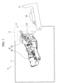
- the developing cartridge 30 is attachable to an apparatus body 10 of an image-forming apparatus.
- the apparatus body 10 includes a housing 11 having an opening 13, and a cover 12 for opening and closing the opening 13.
- the cover 12 is pivotally movable relative to the housing 11 between a closed position indicated by a two-dotted chain line where the cover 12 closes the opening 13 and an open position indicated by a solid line where the cover 12 opens the opening 13.
- a process cartridge 20 is attachable to the apparatus body 10 through the opening 13 in a state where the cover 12 is at the open position.
- the cover 12 has a protruding portion 12A configured to protrude into an interior of the housing 11 in a state where the cover 12 is at the closed position.
- the protruding portion 12A is so shaped that the protruding portion 12A can press a plate 55 (described later) of the developing cartridge 30 in the state where the cover 12 is at the closed position.
- the process cartridge 20 includes the developing cartridge 30 and a drum cartridge 40.
- the drum cartridge 40 includes a drum frame 41, a photosensitive drum 42, and a pair of pressing portions 48.
- the photosensitive drum 42 is rotatable about a drum axis X4 extending in a first direction.
- the drum frame 41 rotatably supports the photosensitive drum 42.
- the pressing portions 48 are configured to press the developing cartridge 30 in a state where the developing cartridge 30 is attached to the drum cartridge 40.
- the pressing portions 48 are positioned at the drum frame 41.
- Each pressing portion 48 includes a spring 48A and a pressing member 48B.
- the pressing member 48B is urged toward the photosensitive drum 42 by the spring 48A.
- the pair of pressing portions 48 are: a first pressing portion 481; and a second pressing portion 482 positioned away from the first pressing portion 481 in the first direction.
- the developing cartridge 30 includes a casing 31, a developing roller 32, a developing memory 51, a holder 52, a holder cover 53, and the plate 55.
- the casing 31 is configured to store toner therein.
- the casing 31 includes: a casing body 31A configured to store the toner; and a gear cover 31B covering at least a part of an agitator gear 60 (described later).
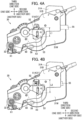
- the gear cover 31B covers an entirety of the agitator gear 60 (see Figs. 4A and 4B ).
- the casing body 31A includes two side walls 31W and a pair of protrusions 58.
- the side walls 31W include a first side wall 31W1 and a second side wall 31W2 positioned apart from the first side wall 31W1 in the first direction.
- the side walls 31W (31W1, 31W2) are at end portions of the casing body 31A in the first direction.
- the protrusions 58 are positioned each at one of the side walls 31W (In Fig. 2 , only one of the protrusions 58 positioned on the side wall 31W1 is illustrated).
- one of the protrusions 58 is positioned at the first side wall 31W1 and the other protrusion 58 is positioned at the second side wall 31W2.
- the protrusions 58 protrude from the respective side walls 31W outward in the first direction.
- the protrusions 58 are urged toward the photosensitive drum 42 by the respective pressing portions 48 in the state where the developing cartridge 30 is attached to the drum cartridge 40. In this way, the casing 31 is pushed by the pressing portions 48 so that the developing roller 32 held by the casing 31 is pressed against the photosensitive drum 42.
- the holder 52 has an elongated shape extending in the third direction.
- the holder 52 has one end portion in the third direction holding the electrical contact surface 51A.
- the developing memory 51 is held at the one end portion of the holder 52 in the third direction.
- the plate 55 is positioned at another end portion of the casing 31 in the second direction.
- the plate 55 is positioned farther away from the developing roller 32 than the holder 52 is from the developing roller 32 in the second direction. Further, the plate 55 is positioned farther away from the developing roller 32 than the agitator gear 60 is from the developing roller 32 in the second direction.
- the plate 55 is movable relative to the casing 31 between a first position illustrated in Fig. 4A (where the plate 55 places the holder 52 at the retracted position) and a second position illustrated in Fig. 4B (where the plate 55 places the holder 52 at the advancing position).
- the plate 55 at the second position is positioned closer to the developing roller 32 in the second direction than the plate 55 at the first position is.
- the plate 55 protrudes out in the second direction from the casing 31 in a state where the plate 55 is at the first position.
- the charger 43 is configured to charge the photosensitive drum 42.
- the charger 43 is a Scorotron-type charger positioned away from the photosensitive drum 42.
- the transfer roller 44 is configured to transfer toner on the photosensitive drum 42 onto a sheet (not illustrated).
- the transfer roller 44 is rotatable about a transfer axis X5 extending in the first direction.
- the transfer roller 44 is in contact with the photosensitive drum 42.
- the transfer roller 44 faces the photosensitive drum 42 in the third direction.
- the first cleaning roller 45 is configured to remove toner deposited on the photosensitive drum 42.
- the first cleaning roller 45 is rotatable about a first cleaning axis X61 extending in the first direction.
- the first cleaning roller 45 is in contact with the photosensitive drum 42.
- the supply roller 33 is configured to supply toner to the developing roller 32.
- the supply roller 33 is rotatable about a supply axis X2 extending in the first direction.
- the supply roller 33 is positioned inside the casing body 31A.
- the electrical contact surface 51A and the agitator axis X3 define a first distance L1 therebetween in the third direction.
- the electrical contact surface 51A and the agitator axis X3 define a second distance L2 therebetween in the third direction, the second distance L2 being greater than the first distance L1.
- the holder 52 is positioned opposite to the agitator gear 60 in the first direction with respect to the gear cover 31B. Further, the holder 52 is positioned opposite to the small diameter gear 62 in the first direction with respect to the large diameter gear 61.
- the interlocking mechanism 100 includes a cam 110 and a spring 120.
- the cam 110 is configured to move in association with the movement of the plate 55 between the first position and the second position.
- the cam 110 is a translation cam (linear cam) which is movable in the second direction relative to the casing 31.
- the cam 110 includes a connecting portion 111 and a cam portion 112.
- the gear cover 31B has a first guide hole 181 and a second guide hole 182.
- the first guide hole 181 and the second guide hole 182 extend throughout a thickness of the gear cover 31B in the first direction.
- the first guide hole 181 and second guide hole 182 are each elongated in the third direction.
- the first boss 52A is inserted in the first guide hole 181. Specifically, the first boss 52A extends through the first guide hole 181.
- the second boss 52B is inserted in the second guide hole 182. Specifically, the second boss 52B extends through the second guide hole 182. With this configuration, the movement of the holder 52 in the third direction is guided by the gear cover 31B.
- the cam portion 112 extends in the second direction from the connecting portion 111. Specifically, the cam portion 112 extends from the connecting portion 111 toward one side in the second direction (toward the right in Fig. 6 ). More specifically, the cam portion 112 extends in the second direction toward the developing roller 32 from the connecting portion 111.
- the cam portion 112 has a base end connected to the connecting portion 111, and a free end apart from the connecting portion 111 in the second direction.
- the cam portion 112 includes a first retaining surface 112A, a sloped surface 112B, and a second retaining surface 112C.
- the first retaining surface 112A, the sloped surface 112B, and the second retaining surface 112C are arrayed in this order from the free end toward the base end of the cam portion 112.
- the developing cartridge 30 according to the first embodiment thus constructed is configured to be attached to the apparatus body 10 through the opening 13 in the state where the cover 12 is at the open position, as illustrated in Fig. 1 .
- the plate 55 is pushed by the protruding portion 12A of the cover 12 so that the plate 55 moves from the first position to the second position.
- the plate 55 is slidably movable in the second direction.
- the plate 55 may be pivotally movably supported by the casing 31.
- a different intervening mechanism may be provided between the cam 110 and the plate 55 to move the cam 110 in interlocking relation to the movement of the plate 55.
- the spring 120 is in contact with the connecting portion 111 of the cam 110 to urge the plate 55 from the second position to the first position through the connecting portion 111.
- the spring may not be in contact with the connecting portion 111 of the cam 110.
- the developing cartridge 30 may include a spring contacting the holder 52. In this case, the spring may urge the holder 52 toward the retracted position from the advancing position to urge the plate 55 from the second position to the first position through the interlocking mechanism 100.
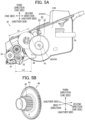
- an interlocking mechanism 200 of the developing cartridge according to the second embodiment includes the spring 120, a rack gear 210, a first pinion gear 220, a worm gear 230, a second pinion gear 240, a shaft 250, and a guide groove 260.
- the rack gear 210 is formed integrally with the plate 155.
- the rack gear 210 is slidably movable in the second direction together with the plate 155.
- the first pinion gear 220 is in meshing engagement with the rack gear 210.
- the first pinion gear 220 includes a first gear 221 and a second gear 222.
- a hole 223 is formed in the first pinion gear 220.
- the shaft 250 extends in the first direction from the gear cover 131B.
- the shaft 250 extends through the hole 223, so that the first pinion gear 220 is rotatable about a first gear axis X8 extending in the first direction.
- the worm gear 230 is rotatable about a worm axis X10 extending in the third direction (assuming that the third direction crosses the first direction and the second direction).
- the gear cover 131B has two support holes 271 and 272.
- the support hole 271 is apart from the support hole 272 in the third direction.
- the worm gear 230 has one end portion inserted in the support hole 271 and another end portion inserted in the support hole 272.
- the worm gear 230 is thus rotatably supported by the gear cover 131B.
- the worm axis X10 is inclined with respect to the third direction (assuming that the third direction is orthogonal to the first direction and the second direction).
- the second pinion gear 240 is in meshing engagement with the worm gear 230.
- the second pinion gear 240 includes a shaft 241, a third gear 242, and a fourth gear 243.
- a holder 152 of the second embodiment has a hole 152C in which the shaft 241 is inserted.
- the second pinion gear 240 is thus rotatable about a second gear axis X9 extending in the first direction.
- the third gear 242 and the fourth gear 243 are rotatable about the second gear axis X9.
- the third gear 242 has an outer diameter greater than an outer diameter of the fourth gear 243.
- the third gear 242 is in meshing engagement with the worm gear 230.
- the guide groove 260 is a slot extending throughout a thickness of the gear cover 131B in the first direction.
- the guide groove 260 extends in the third direction (assuming that the third direction crosses the first direction and the second direction). Specifically, the guide groove 260 extends in parallel to the worm axis X10.
- the guide groove 260 has gear teeth 261.
- the gear teeth 261 are formed at an inner surface of the guide groove 260.
- the fourth gear 243 of the second pinion gear 240 is positioned in the guide groove 260 and is in meshing engagement with the gear teeth 261 of the guide groove 260.
- the guide groove 260 may be provided in a form of a recess having a closed bottom, instead of a slot.
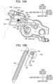
- the plate 155 is pushed by the protruding portion 12A of the cover 12, thereby moving the plate 155 relative to a casing 131 from the first position to the second position as illustrated in Figs. 10A and 10B .
- the rack gear 210 moves toward the one side in the second direction (rightward in Fig. 10A ) to rotate the first pinion gear 220.
- the worm gear 230 in meshing engagement with the second gear 222 of the first pinion gear 220 is caused to rotate.
- a meshing position E1 (see Fig. 9B ) between the second pinion gear 240 and the worm gear 230 moves toward the one side in the third direction (upward in Fig. 9B ).
- the fourth gear 243 of the second pinion gear 240 moves along the guide groove 260 toward the one side in the third direction while rotating over the gear teeth 261 meshing therewith.
- the second pinion gear 240 thus reaches one end of the guide groove 260 at the one side in the third direction (upper end in Fig. 10B ), so that the holder 152 is positioned at the advancing position.
- the holder 152 can move from the retracted position to the advancing position in association with the movement of the plate 155 from the first position to the second position.
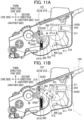
- a developing cartridge according to a third embodiment will next be described with reference to Figs. 11A through 12B , wherein like parts and components are designated by the same reference numerals as those shown in the first embodiment.
- the third embodiment is the same as the first embodiment except a structure in relation to the interlocking mechanism.
- an interlocking mechanism 300 of the developing cartridge according to the third embodiment includes a first link 310, a second link 320, and a spring 330.
- the second link 320 is supported such that the second link 320 is pivotally movable about a second axis X12 extending in the first direction relative to the casing 231.
- the second link 320 has a second slot 322 extending in a direction crossing the third direction.
- the second slot 322 is at a position away from the second axis X12 toward the one side in the second direction.
- the second link 320 includes a third slot 323 extending in a direction crossing the third direction.
- the third slot 323 is at a position away from the second axis X12 toward the other side in the second direction.
- the boss 312 of the first link 310 is inserted in the third slot 323 of the second link 320.
- the second link 320 is connected to the first link 310 by the insertion of the boss 312 in the third slot 323.
- a holder 252 of the third embodiment includes a second pin 252D and a boss 252E.
- the second pin 252D is inserted in the second slot 322 of the second link 320.
- the second link 320 is thus connected to the holder 252 by the insertion of the second pin 252D in the second slot 322.
- a gear cover 231B according to the third embodiment includes a boss 231E.
- the spring 330 is a tension coil spring.
- the spring 330 extends in the third direction.
- the spring 330 has one end in the third direction engaged with the boss 252E of the holder 252.
- the spring 330 has another end in the third direction engaged with the boss 231E of the gear cover 231B.
- the spring 330 urges the holder 252 toward the retracted position from the advancing position.
- the spring 330 urges the plate 255 from the second position toward the first position through the interlocking mechanism 300.
- the developing cartridge may include additional link member at a position between the first link 310 and the second link 320, or between the second link 320 and the holder 252.
- FIGs. 12A and 12B illustrate a modification to the third embodiment including an interlocking mechanism 400.
- a plate 355 according to this modification has a first slot 355D.
- a first link 410 has a first pin 411 inserted in the first slot 355D.
- the first link 410 also has a second slot 412 in which the second pin 252D of the holder 252 is inserted.
- the first link 410 can pivot clockwise about an axis X13 thereof in response to the sliding movement of the plate 355 from the first position illustrated in Fig. 12A to the second position illustrated in Fig. 12B .
- the holder 252 can move from the retracted position to the advancing position.
- the developing cartridge of the disclosure may be used in a monochromatic image-forming apparatus or in a color image-forming apparatus. Further, the plate of the disclosure may be configured to be pushed by a user, rather than by the cover of the image forming apparatus.
- the spring 120, 330 is an example of a spring.
- the interlocking mechanism 100, 20, 300, 400 is an example of an interlocking mechanism.
- the cam 110 of the interlocking mechanism 100 is an example of a cam.
- the sloped surface 112B is an example of a sloped surface.
- the rack gear 210, first pinion gear 220, worm gear 230, second pinion gear 240 of the interlocking mechanism 200 are examples of a rack gear, a first pinion gear, a worm gear and a second pinion gear of the interlocking mechanism.
- the guide groove 260 is an example of a guide groove of the casing.
- the third gear 242 and fourth gear 243 are examples of a third gear and a fourth gear of the second pinion gear.
Landscapes
- Physics & Mathematics (AREA)
- General Physics & Mathematics (AREA)
- Engineering & Computer Science (AREA)
- Computer Vision & Pattern Recognition (AREA)
- Computer Networks & Wireless Communication (AREA)
- Dry Development In Electrophotography (AREA)
- Electrophotography Configuration And Component (AREA)
Priority Applications (1)
| Application Number | Priority Date | Filing Date | Title |
|---|---|---|---|
| EP25165598.1A EP4550059A3 (en) | 2021-03-31 | 2022-02-16 | Developing cartridge |
Applications Claiming Priority (1)
| Application Number | Priority Date | Filing Date | Title |
|---|---|---|---|
| JP2021061271A JP7631997B2 (ja) | 2021-03-31 | 2021-03-31 | 現像カートリッジ |
Related Child Applications (1)
| Application Number | Title | Priority Date | Filing Date |
|---|---|---|---|
| EP25165598.1A Division EP4550059A3 (en) | 2021-03-31 | 2022-02-16 | Developing cartridge |
Publications (3)
| Publication Number | Publication Date |
|---|---|
| EP4068006A1 EP4068006A1 (en) | 2022-10-05 |
| EP4068006C0 EP4068006C0 (en) | 2025-04-09 |
| EP4068006B1 true EP4068006B1 (en) | 2025-04-09 |
Family
ID=80682388
Family Applications (2)
| Application Number | Title | Priority Date | Filing Date |
|---|---|---|---|
| EP22156947.8A Active EP4068006B1 (en) | 2021-03-31 | 2022-02-16 | Developing cartridge |
| EP25165598.1A Pending EP4550059A3 (en) | 2021-03-31 | 2022-02-16 | Developing cartridge |
Family Applications After (1)
| Application Number | Title | Priority Date | Filing Date |
|---|---|---|---|
| EP25165598.1A Pending EP4550059A3 (en) | 2021-03-31 | 2022-02-16 | Developing cartridge |
Country Status (6)
| Country | Link |
|---|---|
| US (3) | US11762312B2 (pl) |
| EP (2) | EP4068006B1 (pl) |
| JP (1) | JP7631997B2 (pl) |
| CN (1) | CN115145134A (pl) |
| ES (1) | ES3023565T3 (pl) |
| PL (1) | PL4068006T3 (pl) |
Families Citing this family (2)
| Publication number | Priority date | Publication date | Assignee | Title |
|---|---|---|---|---|
| JP7631997B2 (ja) * | 2021-03-31 | 2025-02-19 | ブラザー工業株式会社 | 現像カートリッジ |
| JP2026007162A (ja) * | 2024-07-02 | 2026-01-16 | ブラザー工業株式会社 | 現像カートリッジ |
Family Cites Families (17)
| Publication number | Priority date | Publication date | Assignee | Title |
|---|---|---|---|---|
| JP3432087B2 (ja) * | 1996-08-29 | 2003-07-28 | キヤノン株式会社 | プロセスカートリッジ及び電子写真画像形成装置 |
| JP2000315006A (ja) * | 1999-04-30 | 2000-11-14 | Canon Inc | 現像装置、プロセスカートリッジ、電子写真画像形成装置、および、給電部品 |
| JP2004061596A (ja) | 2002-07-25 | 2004-02-26 | Canon Inc | 不揮発性メモリ搭載プロセスカートリッジを用いた画像形成装置 |
| JP5115607B2 (ja) * | 2010-08-31 | 2013-01-09 | ブラザー工業株式会社 | キャップおよびカートリッジ |
| JP5904075B2 (ja) * | 2012-09-28 | 2016-04-13 | ブラザー工業株式会社 | 画像形成装置 |
| KR101585058B1 (ko) | 2014-03-12 | 2016-01-13 | 삼성전자주식회사 | 카트리지 및 이를 채용한 전자사진방식 화상형성장치 |
| JP6582972B2 (ja) | 2015-12-25 | 2019-10-02 | ブラザー工業株式会社 | 現像カートリッジ |
| JP2017173619A (ja) | 2016-03-24 | 2017-09-28 | ブラザー工業株式会社 | 現像カートリッジ |
| JP2017173648A (ja) * | 2016-03-25 | 2017-09-28 | ブラザー工業株式会社 | 現像カートリッジ |
| JP2017181527A (ja) * | 2016-03-28 | 2017-10-05 | ブラザー工業株式会社 | 現像カートリッジ |
| JP6759835B2 (ja) | 2016-08-10 | 2020-09-23 | ブラザー工業株式会社 | 現像カートリッジ |
| CN107885057B (zh) | 2016-09-30 | 2022-04-22 | 兄弟工业株式会社 | 显影盒 |
| JP6711268B2 (ja) * | 2016-12-28 | 2020-06-17 | ブラザー工業株式会社 | 現像カートリッジ |
| EP3382459B1 (en) * | 2017-03-27 | 2019-10-16 | Brother Kogyo Kabushiki Kaisha | Developing cartridge |
| JP6809337B2 (ja) * | 2017-03-30 | 2021-01-06 | ブラザー工業株式会社 | 現像カートリッジ |
| JP6880925B2 (ja) * | 2017-03-30 | 2021-06-02 | ブラザー工業株式会社 | 現像カートリッジ |
| JP7631997B2 (ja) * | 2021-03-31 | 2025-02-19 | ブラザー工業株式会社 | 現像カートリッジ |
-
2021
- 2021-03-31 JP JP2021061271A patent/JP7631997B2/ja active Active
-
2022
- 2022-02-15 US US17/672,323 patent/US11762312B2/en active Active
- 2022-02-16 ES ES22156947T patent/ES3023565T3/es active Active
- 2022-02-16 PL PL22156947.8T patent/PL4068006T3/pl unknown
- 2022-02-16 EP EP22156947.8A patent/EP4068006B1/en active Active
- 2022-02-16 EP EP25165598.1A patent/EP4550059A3/en active Pending
- 2022-03-29 CN CN202210317481.3A patent/CN115145134A/zh active Pending
-
2023
- 2023-08-03 US US18/364,635 patent/US12210300B2/en active Active
-
2024
- 2024-12-16 US US18/982,727 patent/US20250116953A1/en active Pending
Also Published As
| Publication number | Publication date |
|---|---|
| US11762312B2 (en) | 2023-09-19 |
| EP4550059A2 (en) | 2025-05-07 |
| CN115145134A (zh) | 2022-10-04 |
| ES3023565T3 (en) | 2025-06-02 |
| US20220317589A1 (en) | 2022-10-06 |
| EP4550059A3 (en) | 2025-07-30 |
| US12210300B2 (en) | 2025-01-28 |
| PL4068006T3 (pl) | 2025-08-04 |
| EP4068006A1 (en) | 2022-10-05 |
| EP4068006C0 (en) | 2025-04-09 |
| US20230375958A1 (en) | 2023-11-23 |
| JP7631997B2 (ja) | 2025-02-19 |
| US20250116953A1 (en) | 2025-04-10 |
| JP2022157182A (ja) | 2022-10-14 |
Similar Documents
| Publication | Publication Date | Title |
|---|---|---|
| US20250116953A1 (en) | Developing cartridge including movable plate for moving holder holding electrical contact surface | |
| US9612552B2 (en) | Cartridge and image forming apparatus | |
| US10203658B2 (en) | Image forming apparatus having electrical contact | |
| CN114942576B (zh) | 显影盒 | |
| EP2843480A1 (en) | Cartridge | |
| KR20090090378A (ko) | 카트리지 및 전자 사진 화상 형성 장치 | |
| US10459393B2 (en) | Image-forming apparatus | |
| JP2006113521A (ja) | プロセスカートリッジ及び電子写真画像形成装置 | |
| CN221551072U (zh) | 一种显影盒 | |
| CN115755549B (zh) | 显影盒 | |
| JP6256398B2 (ja) | 印刷装置 | |
| CN212515361U (zh) | 一种显影盒 | |
| CN109725520B (zh) | 一种显影盒及其处理盒 | |
| CN104076641A (zh) | 图像形成装置 | |
| CN206757299U (zh) | 显影剂盒 | |
| US12498666B2 (en) | Image forming apparatus and process cartridge with separatable developing roller from photoconductor drum | |
| EP4307050B1 (en) | Developing cartridge | |
| JP2011181469A (ja) | スイッチ作動装置、並びにこれを備えたインターロック機構及び画像形成装置 | |
| JP4835262B2 (ja) | 画像形成装置 | |
| US12529993B2 (en) | Developing cartridge | |
| CN219676448U (zh) | 显影盒及图像形成装置 | |
| JP6958032B2 (ja) | 画像形成装置 | |
| JP2020166006A (ja) | 現像カートリッジ | |
| JPH09258635A (ja) | プロセスカートリッジ | |
| JP2001019176A (ja) | 給紙装置 |
Legal Events
| Date | Code | Title | Description |
|---|---|---|---|
| PUAI | Public reference made under article 153(3) epc to a published international application that has entered the european phase |
Free format text: ORIGINAL CODE: 0009012 |
|
| STAA | Information on the status of an ep patent application or granted ep patent |
Free format text: STATUS: THE APPLICATION HAS BEEN PUBLISHED |
|
| AK | Designated contracting states |
Kind code of ref document: A1 Designated state(s): AL AT BE BG CH CY CZ DE DK EE ES FI FR GB GR HR HU IE IS IT LI LT LU LV MC MK MT NL NO PL PT RO RS SE SI SK SM TR |
|
| STAA | Information on the status of an ep patent application or granted ep patent |
Free format text: STATUS: REQUEST FOR EXAMINATION WAS MADE |
|
| 17P | Request for examination filed |
Effective date: 20230327 |
|
| P01 | Opt-out of the competence of the unified patent court (upc) registered |
Effective date: 20230529 |
|
| GRAP | Despatch of communication of intention to grant a patent |
Free format text: ORIGINAL CODE: EPIDOSNIGR1 |
|
| STAA | Information on the status of an ep patent application or granted ep patent |
Free format text: STATUS: GRANT OF PATENT IS INTENDED |
|
| INTG | Intention to grant announced |
Effective date: 20241028 |
|
| GRAS | Grant fee paid |
Free format text: ORIGINAL CODE: EPIDOSNIGR3 |
|
| GRAA | (expected) grant |
Free format text: ORIGINAL CODE: 0009210 |
|
| STAA | Information on the status of an ep patent application or granted ep patent |
Free format text: STATUS: THE PATENT HAS BEEN GRANTED |
|
| P04 | Withdrawal of opt-out of the competence of the unified patent court (upc) registered |
Free format text: CASE NUMBER: APP_7527/2025 Effective date: 20250213 |
|
| AK | Designated contracting states |
Kind code of ref document: B1 Designated state(s): AL AT BE BG CH CY CZ DE DK EE ES FI FR GB GR HR HU IE IS IT LI LT LU LV MC MK MT NL NO PL PT RO RS SE SI SK SM TR |
|
| REG | Reference to a national code |
Ref country code: GB Ref legal event code: FG4D |
|
| REG | Reference to a national code |
Ref country code: CH Ref legal event code: EP |
|
| REG | Reference to a national code |
Ref country code: DE Ref legal event code: R096 Ref document number: 602022012750 Country of ref document: DE |
|
| REG | Reference to a national code |
Ref country code: IE Ref legal event code: FG4D |
|
| U01 | Request for unitary effect filed |
Effective date: 20250411 |
|
| U07 | Unitary effect registered |
Designated state(s): AT BE BG DE DK EE FI FR IT LT LU LV MT NL PT RO SE SI Effective date: 20250416 |
|
| REG | Reference to a national code |
Ref country code: ES Ref legal event code: FG2A Ref document number: 3023565 Country of ref document: ES Kind code of ref document: T3 Effective date: 20250602 |
|
| PG25 | Lapsed in a contracting state [announced via postgrant information from national office to epo] |
Ref country code: GR Free format text: LAPSE BECAUSE OF FAILURE TO SUBMIT A TRANSLATION OF THE DESCRIPTION OR TO PAY THE FEE WITHIN THE PRESCRIBED TIME-LIMIT Effective date: 20250710 Ref country code: NO Free format text: LAPSE BECAUSE OF FAILURE TO SUBMIT A TRANSLATION OF THE DESCRIPTION OR TO PAY THE FEE WITHIN THE PRESCRIBED TIME-LIMIT Effective date: 20250709 |
|
| PG25 | Lapsed in a contracting state [announced via postgrant information from national office to epo] |
Ref country code: HR Free format text: LAPSE BECAUSE OF FAILURE TO SUBMIT A TRANSLATION OF THE DESCRIPTION OR TO PAY THE FEE WITHIN THE PRESCRIBED TIME-LIMIT Effective date: 20250409 |
|
| PG25 | Lapsed in a contracting state [announced via postgrant information from national office to epo] |
Ref country code: RS Free format text: LAPSE BECAUSE OF FAILURE TO SUBMIT A TRANSLATION OF THE DESCRIPTION OR TO PAY THE FEE WITHIN THE PRESCRIBED TIME-LIMIT Effective date: 20250709 |
|
| PG25 | Lapsed in a contracting state [announced via postgrant information from national office to epo] |
Ref country code: IS Free format text: LAPSE BECAUSE OF FAILURE TO SUBMIT A TRANSLATION OF THE DESCRIPTION OR TO PAY THE FEE WITHIN THE PRESCRIBED TIME-LIMIT Effective date: 20250809 |
|
| PG25 | Lapsed in a contracting state [announced via postgrant information from national office to epo] |
Ref country code: SM Free format text: LAPSE BECAUSE OF FAILURE TO SUBMIT A TRANSLATION OF THE DESCRIPTION OR TO PAY THE FEE WITHIN THE PRESCRIBED TIME-LIMIT Effective date: 20250409 |
|
| PG25 | Lapsed in a contracting state [announced via postgrant information from national office to epo] |
Ref country code: CZ Free format text: LAPSE BECAUSE OF FAILURE TO SUBMIT A TRANSLATION OF THE DESCRIPTION OR TO PAY THE FEE WITHIN THE PRESCRIBED TIME-LIMIT Effective date: 20250409 |
|
| PG25 | Lapsed in a contracting state [announced via postgrant information from national office to epo] |
Ref country code: SK Free format text: LAPSE BECAUSE OF FAILURE TO SUBMIT A TRANSLATION OF THE DESCRIPTION OR TO PAY THE FEE WITHIN THE PRESCRIBED TIME-LIMIT Effective date: 20250409 |
|
| PLBE | No opposition filed within time limit |
Free format text: ORIGINAL CODE: 0009261 |
|
| STAA | Information on the status of an ep patent application or granted ep patent |
Free format text: STATUS: NO OPPOSITION FILED WITHIN TIME LIMIT |
|
| REG | Reference to a national code |
Ref country code: CH Ref legal event code: L10 Free format text: ST27 STATUS EVENT CODE: U-0-0-L10-L00 (AS PROVIDED BY THE NATIONAL OFFICE) Effective date: 20260218 |
|
| U20 | Renewal fee for the european patent with unitary effect paid |
Year of fee payment: 5 Effective date: 20260112 |
|
| 26N | No opposition filed |
Effective date: 20260112 |
|
| PGFP | Annual fee paid to national office [announced via postgrant information from national office to epo] |
Ref country code: GB Payment date: 20260113 Year of fee payment: 5 |
|
| PGFP | Annual fee paid to national office [announced via postgrant information from national office to epo] |
Ref country code: ES Payment date: 20260304 Year of fee payment: 5 |
|
| PGFP | Annual fee paid to national office [announced via postgrant information from national office to epo] |
Ref country code: PL Payment date: 20260112 Year of fee payment: 5 |