EP4067155A1 - Parkverfahren und -vorrichtung - Google Patents
Parkverfahren und -vorrichtung Download PDFInfo
- Publication number
- EP4067155A1 EP4067155A1 EP21741762.5A EP21741762A EP4067155A1 EP 4067155 A1 EP4067155 A1 EP 4067155A1 EP 21741762 A EP21741762 A EP 21741762A EP 4067155 A1 EP4067155 A1 EP 4067155A1
- Authority
- EP
- European Patent Office
- Prior art keywords
- vehicle
- torque
- controlling
- pedal
- parking
- Prior art date
- Legal status (The legal status is an assumption and is not a legal conclusion. Google has not performed a legal analysis and makes no representation as to the accuracy of the status listed.)
- Pending
Links
Images

Classifications
-
- B—PERFORMING OPERATIONS; TRANSPORTING
- B60—VEHICLES IN GENERAL
- B60L—PROPULSION OF ELECTRICALLY-PROPELLED VEHICLES; SUPPLYING ELECTRIC POWER FOR AUXILIARY EQUIPMENT OF ELECTRICALLY-PROPELLED VEHICLES; ELECTRODYNAMIC BRAKE SYSTEMS FOR VEHICLES IN GENERAL; MAGNETIC SUSPENSION OR LEVITATION FOR VEHICLES; MONITORING OPERATING VARIABLES OF ELECTRICALLY-PROPELLED VEHICLES; ELECTRIC SAFETY DEVICES FOR ELECTRICALLY-PROPELLED VEHICLES
- B60L7/00—Electrodynamic brake systems for vehicles in general
- B60L7/24—Electrodynamic brake systems for vehicles in general with additional mechanical or electromagnetic braking
- B60L7/26—Controlling the braking effect
-
- B—PERFORMING OPERATIONS; TRANSPORTING
- B60—VEHICLES IN GENERAL
- B60L—PROPULSION OF ELECTRICALLY-PROPELLED VEHICLES; SUPPLYING ELECTRIC POWER FOR AUXILIARY EQUIPMENT OF ELECTRICALLY-PROPELLED VEHICLES; ELECTRODYNAMIC BRAKE SYSTEMS FOR VEHICLES IN GENERAL; MAGNETIC SUSPENSION OR LEVITATION FOR VEHICLES; MONITORING OPERATING VARIABLES OF ELECTRICALLY-PROPELLED VEHICLES; ELECTRIC SAFETY DEVICES FOR ELECTRICALLY-PROPELLED VEHICLES
- B60L15/00—Methods, circuits, or devices for controlling the traction-motor speed of electrically-propelled vehicles
- B60L15/20—Methods, circuits, or devices for controlling the traction-motor speed of electrically-propelled vehicles for control of the vehicle or its driving motor to achieve a desired performance, e.g. speed, torque, programmed variation of speed
- B60L15/2009—Methods, circuits, or devices for controlling the traction-motor speed of electrically-propelled vehicles for control of the vehicle or its driving motor to achieve a desired performance, e.g. speed, torque, programmed variation of speed for braking
- B60L15/2018—Methods, circuits, or devices for controlling the traction-motor speed of electrically-propelled vehicles for control of the vehicle or its driving motor to achieve a desired performance, e.g. speed, torque, programmed variation of speed for braking for braking on a slope
-
- B—PERFORMING OPERATIONS; TRANSPORTING
- B60—VEHICLES IN GENERAL
- B60T—VEHICLE BRAKE CONTROL SYSTEMS OR PARTS THEREOF; BRAKE CONTROL SYSTEMS OR PARTS THEREOF, IN GENERAL; ARRANGEMENT OF BRAKING ELEMENTS ON VEHICLES IN GENERAL; PORTABLE DEVICES FOR PREVENTING UNWANTED MOVEMENT OF VEHICLES; VEHICLE MODIFICATIONS TO FACILITATE COOLING OF BRAKES
- B60T7/00—Brake-action initiating means
- B60T7/12—Brake-action initiating means for automatic initiation; for initiation not subject to will of driver or passenger
-
- B—PERFORMING OPERATIONS; TRANSPORTING
- B60—VEHICLES IN GENERAL
- B60T—VEHICLE BRAKE CONTROL SYSTEMS OR PARTS THEREOF; BRAKE CONTROL SYSTEMS OR PARTS THEREOF, IN GENERAL; ARRANGEMENT OF BRAKING ELEMENTS ON VEHICLES IN GENERAL; PORTABLE DEVICES FOR PREVENTING UNWANTED MOVEMENT OF VEHICLES; VEHICLE MODIFICATIONS TO FACILITATE COOLING OF BRAKES
- B60T8/00—Arrangements for adjusting wheel-braking force to meet varying vehicular or ground-surface conditions, e.g. limiting or varying distribution of braking force
- B60T8/26—Arrangements for adjusting wheel-braking force to meet varying vehicular or ground-surface conditions, e.g. limiting or varying distribution of braking force characterised by producing differential braking between front and rear wheels
- B60T8/262—Arrangements for adjusting wheel-braking force to meet varying vehicular or ground-surface conditions, e.g. limiting or varying distribution of braking force characterised by producing differential braking between front and rear wheels using valves with stepped characteristics
- B60T8/265—Arrangements for adjusting wheel-braking force to meet varying vehicular or ground-surface conditions, e.g. limiting or varying distribution of braking force characterised by producing differential braking between front and rear wheels using valves with stepped characteristics for hydraulic brake systems
-
- B—PERFORMING OPERATIONS; TRANSPORTING
- B60—VEHICLES IN GENERAL
- B60T—VEHICLE BRAKE CONTROL SYSTEMS OR PARTS THEREOF; BRAKE CONTROL SYSTEMS OR PARTS THEREOF, IN GENERAL; ARRANGEMENT OF BRAKING ELEMENTS ON VEHICLES IN GENERAL; PORTABLE DEVICES FOR PREVENTING UNWANTED MOVEMENT OF VEHICLES; VEHICLE MODIFICATIONS TO FACILITATE COOLING OF BRAKES
- B60T8/00—Arrangements for adjusting wheel-braking force to meet varying vehicular or ground-surface conditions, e.g. limiting or varying distribution of braking force
- B60T8/32—Arrangements for adjusting wheel-braking force to meet varying vehicular or ground-surface conditions, e.g. limiting or varying distribution of braking force responsive to a speed condition, e.g. acceleration or deceleration
- B60T8/52—Torque sensing, i.e. wherein the braking action is controlled by forces producing or tending to produce a twisting or rotating motion on a braked rotating member
-
- B—PERFORMING OPERATIONS; TRANSPORTING
- B60—VEHICLES IN GENERAL
- B60K—ARRANGEMENT OR MOUNTING OF PROPULSION UNITS OR OF TRANSMISSIONS IN VEHICLES; ARRANGEMENT OR MOUNTING OF PLURAL DIVERSE PRIME-MOVERS IN VEHICLES; AUXILIARY DRIVES FOR VEHICLES; INSTRUMENTATION OR DASHBOARDS FOR VEHICLES; ARRANGEMENTS IN CONNECTION WITH COOLING, AIR INTAKE, GAS EXHAUST OR FUEL SUPPLY OF PROPULSION UNITS IN VEHICLES
- B60K26/00—Arrangement or mounting of propulsion-unit control devices in vehicles
- B60K26/02—Arrangement or mounting of propulsion-unit control devices in vehicles of initiating means or elements
- B60K2026/025—Input devices for controlling electric drive motors
-
- B—PERFORMING OPERATIONS; TRANSPORTING
- B60—VEHICLES IN GENERAL
- B60L—PROPULSION OF ELECTRICALLY-PROPELLED VEHICLES; SUPPLYING ELECTRIC POWER FOR AUXILIARY EQUIPMENT OF ELECTRICALLY-PROPELLED VEHICLES; ELECTRODYNAMIC BRAKE SYSTEMS FOR VEHICLES IN GENERAL; MAGNETIC SUSPENSION OR LEVITATION FOR VEHICLES; MONITORING OPERATING VARIABLES OF ELECTRICALLY-PROPELLED VEHICLES; ELECTRIC SAFETY DEVICES FOR ELECTRICALLY-PROPELLED VEHICLES
- B60L2240/00—Control parameters of input or output; Target parameters
- B60L2240/10—Vehicle control parameters
- B60L2240/12—Speed
-
- B—PERFORMING OPERATIONS; TRANSPORTING
- B60—VEHICLES IN GENERAL
- B60L—PROPULSION OF ELECTRICALLY-PROPELLED VEHICLES; SUPPLYING ELECTRIC POWER FOR AUXILIARY EQUIPMENT OF ELECTRICALLY-PROPELLED VEHICLES; ELECTRODYNAMIC BRAKE SYSTEMS FOR VEHICLES IN GENERAL; MAGNETIC SUSPENSION OR LEVITATION FOR VEHICLES; MONITORING OPERATING VARIABLES OF ELECTRICALLY-PROPELLED VEHICLES; ELECTRIC SAFETY DEVICES FOR ELECTRICALLY-PROPELLED VEHICLES
- B60L2240/00—Control parameters of input or output; Target parameters
- B60L2240/40—Drive Train control parameters
- B60L2240/42—Drive Train control parameters related to electric machines
- B60L2240/423—Torque
-
- B—PERFORMING OPERATIONS; TRANSPORTING
- B60—VEHICLES IN GENERAL
- B60L—PROPULSION OF ELECTRICALLY-PROPELLED VEHICLES; SUPPLYING ELECTRIC POWER FOR AUXILIARY EQUIPMENT OF ELECTRICALLY-PROPELLED VEHICLES; ELECTRODYNAMIC BRAKE SYSTEMS FOR VEHICLES IN GENERAL; MAGNETIC SUSPENSION OR LEVITATION FOR VEHICLES; MONITORING OPERATING VARIABLES OF ELECTRICALLY-PROPELLED VEHICLES; ELECTRIC SAFETY DEVICES FOR ELECTRICALLY-PROPELLED VEHICLES
- B60L2240/00—Control parameters of input or output; Target parameters
- B60L2240/60—Navigation input
- B60L2240/64—Road conditions
- B60L2240/642—Slope of road
-
- B—PERFORMING OPERATIONS; TRANSPORTING
- B60—VEHICLES IN GENERAL
- B60L—PROPULSION OF ELECTRICALLY-PROPELLED VEHICLES; SUPPLYING ELECTRIC POWER FOR AUXILIARY EQUIPMENT OF ELECTRICALLY-PROPELLED VEHICLES; ELECTRODYNAMIC BRAKE SYSTEMS FOR VEHICLES IN GENERAL; MAGNETIC SUSPENSION OR LEVITATION FOR VEHICLES; MONITORING OPERATING VARIABLES OF ELECTRICALLY-PROPELLED VEHICLES; ELECTRIC SAFETY DEVICES FOR ELECTRICALLY-PROPELLED VEHICLES
- B60L2250/00—Driver interactions
- B60L2250/24—Driver interactions by lever actuation
-
- B—PERFORMING OPERATIONS; TRANSPORTING
- B60—VEHICLES IN GENERAL
- B60L—PROPULSION OF ELECTRICALLY-PROPELLED VEHICLES; SUPPLYING ELECTRIC POWER FOR AUXILIARY EQUIPMENT OF ELECTRICALLY-PROPELLED VEHICLES; ELECTRODYNAMIC BRAKE SYSTEMS FOR VEHICLES IN GENERAL; MAGNETIC SUSPENSION OR LEVITATION FOR VEHICLES; MONITORING OPERATING VARIABLES OF ELECTRICALLY-PROPELLED VEHICLES; ELECTRIC SAFETY DEVICES FOR ELECTRICALLY-PROPELLED VEHICLES
- B60L2250/00—Driver interactions
- B60L2250/26—Driver interactions by pedal actuation
-
- B—PERFORMING OPERATIONS; TRANSPORTING
- B60—VEHICLES IN GENERAL
- B60L—PROPULSION OF ELECTRICALLY-PROPELLED VEHICLES; SUPPLYING ELECTRIC POWER FOR AUXILIARY EQUIPMENT OF ELECTRICALLY-PROPELLED VEHICLES; ELECTRODYNAMIC BRAKE SYSTEMS FOR VEHICLES IN GENERAL; MAGNETIC SUSPENSION OR LEVITATION FOR VEHICLES; MONITORING OPERATING VARIABLES OF ELECTRICALLY-PROPELLED VEHICLES; ELECTRIC SAFETY DEVICES FOR ELECTRICALLY-PROPELLED VEHICLES
- B60L2260/00—Operating Modes
- B60L2260/20—Drive modes; Transition between modes
- B60L2260/22—Standstill, e.g. zero speed
-
- B—PERFORMING OPERATIONS; TRANSPORTING
- B60—VEHICLES IN GENERAL
- B60T—VEHICLE BRAKE CONTROL SYSTEMS OR PARTS THEREOF; BRAKE CONTROL SYSTEMS OR PARTS THEREOF, IN GENERAL; ARRANGEMENT OF BRAKING ELEMENTS ON VEHICLES IN GENERAL; PORTABLE DEVICES FOR PREVENTING UNWANTED MOVEMENT OF VEHICLES; VEHICLE MODIFICATIONS TO FACILITATE COOLING OF BRAKES
- B60T2201/00—Particular use of vehicle brake systems; Special systems using also the brakes; Special software modules within the brake system controller
- B60T2201/06—Hill holder; Start aid systems on inclined road
-
- B—PERFORMING OPERATIONS; TRANSPORTING
- B60—VEHICLES IN GENERAL
- B60T—VEHICLE BRAKE CONTROL SYSTEMS OR PARTS THEREOF; BRAKE CONTROL SYSTEMS OR PARTS THEREOF, IN GENERAL; ARRANGEMENT OF BRAKING ELEMENTS ON VEHICLES IN GENERAL; PORTABLE DEVICES FOR PREVENTING UNWANTED MOVEMENT OF VEHICLES; VEHICLE MODIFICATIONS TO FACILITATE COOLING OF BRAKES
- B60T2210/00—Detection or estimation of road or environment conditions; Detection or estimation of road shapes
- B60T2210/10—Detection or estimation of road conditions
-
- B—PERFORMING OPERATIONS; TRANSPORTING
- B60—VEHICLES IN GENERAL
- B60T—VEHICLE BRAKE CONTROL SYSTEMS OR PARTS THEREOF; BRAKE CONTROL SYSTEMS OR PARTS THEREOF, IN GENERAL; ARRANGEMENT OF BRAKING ELEMENTS ON VEHICLES IN GENERAL; PORTABLE DEVICES FOR PREVENTING UNWANTED MOVEMENT OF VEHICLES; VEHICLE MODIFICATIONS TO FACILITATE COOLING OF BRAKES
- B60T2270/00—Further aspects of brake control systems not otherwise provided for
- B60T2270/60—Regenerative braking
- B60T2270/604—Merging friction therewith; Adjusting their repartition
-
- Y—GENERAL TAGGING OF NEW TECHNOLOGICAL DEVELOPMENTS; GENERAL TAGGING OF CROSS-SECTIONAL TECHNOLOGIES SPANNING OVER SEVERAL SECTIONS OF THE IPC; TECHNICAL SUBJECTS COVERED BY FORMER USPC CROSS-REFERENCE ART COLLECTIONS [XRACs] AND DIGESTS
- Y02—TECHNOLOGIES OR APPLICATIONS FOR MITIGATION OR ADAPTATION AGAINST CLIMATE CHANGE
- Y02T—CLIMATE CHANGE MITIGATION TECHNOLOGIES RELATED TO TRANSPORTATION
- Y02T10/00—Road transport of goods or passengers
- Y02T10/60—Other road transportation technologies with climate change mitigation effect
- Y02T10/72—Electric energy management in electromobility
Definitions
- the present disclosure relates to the technical field of vehicle driving, and particularly relates to a parking method and an apparatus.
- OPD refers to a controlling function that the accelerator pedal, the accelerated, constant-speed and decelerated travelling of a new energy vehicle can be realized by operating the accelerator pedal alone, and by completely releasing the accelerator pedal, the new energy vehicle can be completely stationary. It can reduce the usage frequency of the pedal, improve the capacity utilization ratio and the driving experience of the vehicle, and reduce driving fatigue.
- the current OPD is realized mainly by the electric-motor controlling in the vehicles, which relies on the recovering capacity of the electric driving system and the electric-motor controlling level of the vehicles.
- the electric driving system loses the recovery ability under the condition of full battery power, and there is a risk of being incapable of brake-stopping, which results in a poor effect of brake-stopping.
- the present disclosure provides a parking method and an apparatus, to solve the problem of a poor effect of the brake-stopping in the OPD.
- an embodiment of the present disclosure provides a parking method, wherein the parking method is applied to a vehicle having a hydraulic braking system, and the method includes:
- the method further includes:
- the method further includes:
- the method further includes:
- the hydraulic-compensation increasing instruction includes an instruction for increasing a hydraulic braking force, wherein the hydraulic braking force enables the vehicle to stop within a preset slope range.
- an embodiment of the present disclosure provides a parking apparatus, wherein the parking apparatus is applied to a vehicle having a hydraulic braking system, and the apparatus includes:
- the apparatus further includes:
- the apparatus further includes:
- the apparatus further includes:
- the hydraulic-compensation increasing instruction includes an instruction for increasing a hydraulic braking force, wherein the hydraulic braking force enables the vehicle to stop within a preset slope range.
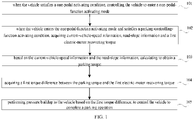
- the parking method according to the embodiments of the present disclosure includes, when the vehicle satisfies a one-pedal activating condition, controlling the vehicle to enter a one-pedal-function activating mode; when the vehicle enters the one-pedal-function activating mode and satisfies a parking-controlling-function activating condition, acquiring current-vehicle-speed information, road-slope information and a first electric-motor recovering torque; based on the current-vehicle-speed information and the road-slope information, calculating to obtain a parking torque; acquiring a first torque difference between the parking torque and the first electric-motor recovering torque; and performing pressure buildup to the vehicle based on the first torque difference.
- the vehicle may also perform braking compensation to the vehicle by means of the pressure buildup, to control the vehicle to complete the parking operation, i.e., to enable the vehicle to complete the brake-stopping, which can improve the effect of the brake-stopping of the vehicle, and ensure the drive uniformity.
- FIG. 1 shows a flow chart of the steps of the parking method according to the first embodiment of the present disclosure.
- the parking method may be applied to a vehicle having a hydraulic braking system.
- the parking method may particularly include the following steps:
- Step 101 when the vehicle satisfies a one-pedal activating condition, controlling the vehicle to enter a one-pedal-function activating mode.
- the vehicle when the vehicle satisfies the following conditions, the vehicle can enter the one-pedal-function activating mode: a one-pedal selecting switch is turned on, the power system has no serious failure, the accelerator pedal has no failure, the snowfield mode is not activated, the current road slope is less than a road slope calibration value, and so on.
- the condition is not limited to those.
- the vehicle may also enter the one-pedal-function activating mode when the vehicle is in other conditions, which may particularly be determined according to actual situations, and is not limited in the embodiments of the present disclosure.
- the road slope calibration value may be adjusted according to particular application scenes, and may be 30%, and may also be 35%, which is not particularly limited in the embodiments of the present disclosure.
- step 102 is executed.
- Step 102 when the vehicle enters the one-pedal-function activating mode and satisfies a parking-controlling-function activating condition, acquiring current-vehicle-speed information, road-slope information and a first electric-motor recovering torque.
- the vehicle when the vehicle satisfies the following conditions at the same time, the vehicle satisfies the parking-controlling-function activating condition: the vehicle is in a start-up completing state; the one-pedal function is activated; the current vehicle speed is less than a vehicle-speed calibration value within a vehicle-speed-continuation calibration duration; the accelerator-pedal depth is less than a depth calibration value; the accelerator pedal is not trodden within a pedal-continuation calibration duration or the brake-master-cylinder pressure value of the accelerator pedal is less than a pressure calibration value within a continuation calibration duration; the worming function is not activated; the current gear is in the Drive (D) gear; the Electrical Park Brake (EPB) and the other electronic braking systems are not activated, and so on.
- the vehicle is in a start-up completing state
- the one-pedal function is activated
- the current vehicle speed is less than a vehicle-speed calibration value within a vehicle-speed-continuation calibration duration
- the accelerator-pedal depth is less
- condition is not limited to those.
- the vehicle-speed calibration value may be 10 kilometers per hour, the vehicle-speed-continuation calibration duration may be 500 milliseconds, the depth calibration value may be 1%, the pressure calibration value may be 4.5Pa, and the pedal-continuation calibration duration may be 100 milliseconds.
- Each of the calibration values may be adjusted according to particular application scenes, which is not particularly limited in the embodiments of the present disclosure.
- the parking-controlling-function of the vehicle When the vehicle enters the one-pedal-function activating mode and satisfies a parking-controlling-function activating condition, the parking-controlling-function of the vehicle is activated, and the current-vehicle-speed information, the road-slope information and the first electric-motor recovering torque of the vehicle are acquired.
- the step 103 is executed.
- Step 103 based on the current-vehicle-speed information and the road-slope information, calculating to obtain a parking torque.
- the parking torque is the electric-motor torque.
- Table 1 shows a schematic diagram of the vehicle speed (Vehicle Speed), the road slope (Road Slope) and the parking torque (Torque, T) according to an embodiment of the present disclosure.
- the parking torque is a scalable quantity (To Be Determine, TBD).
- the theoretical calculating method of the TBD of the parking torque may include: based on the driving performance and the comfortableness, providing the relation between the vehicle acceleration (m/s 2 ) and the vehicle speed (kph), wherein the vehicle acceleration is related to the actual state of the vehicle. Assuming that the acceleration is a n , the following table provides a correspondence relation between the one-pedal vehicle acceleration and the one-pedal vehicle speed.
- the electric-motor torque is an unknown parameter, and the electric-motor torque may be obtained by calculation based on the above formula, i.e., calculating out the parking torque.
- the calculated-out parking torque is a theoretical value
- the actual value may be obtained by trimming on basis of the theoretical value, to adapt to the actual vehicle, which may particularly be determined according to actual situations, and the particular numerical value of the actual value is not limited in the embodiments of the present disclosure.
- step 104 is executed.
- Step 104 acquiring a first torque difference between the parking torque and the first electric-motor recovering torque.
- the parking torque of the vehicle is obtained by calculation, by referring to the electric-motor recovering torque obtained in the step 102, subtracting the parking torque and the first electric-motor recovering torque, the first torque difference can be obtained. Further, the step 105 may be performed in the hydraulic braking system of the vehicle according to the first torque difference.
- Step 105 performing pressure buildup to the vehicle based on the first torque difference, to control the vehicle to complete a parking operation.
- the pressure buildup refers to building up a liquid pressure.
- the hydraulic braking system of the vehicle builds up the liquid pressure with the first torque difference as the controlling target, thereby providing the braking force to the entire vehicle to realize the braking, i.e., controlling the vehicle to complete the parking operation.
- the parking method includes, when the vehicle satisfies a one-pedal activating condition, controlling the vehicle to enter a one-pedal-function activating mode; when the vehicle enters the one-pedal-function activating mode and satisfies a parking-controlling-function activating condition, acquiring current-vehicle-speed information, road-slope information and a first electric-motor recovering torque; based on the current-vehicle-speed information and the road-slope information, calculating to obtain a parking torque; acquiring a first torque difference between the parking torque and the first electric-motor recovering torque; and performing pressure buildup to the vehicle based on the first torque difference.
- the vehicle may also perform braking compensation to the vehicle by means of the pressure buildup, to control the vehicle to complete the parking operation, i.e., to enable the vehicle to complete the brake-stopping, which can improve the effect of the brake-stopping of the vehicle, and ensure the drive uniformity.
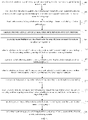
- FIG. 2 shows a flow chart of the steps of the parking method according to the second embodiment of the present disclosure.
- the parking method may be applied to a vehicle having a hydraulic braking system.
- the parking method may particularly include the following steps:
- Step 201 when the vehicle satisfies a one-pedal activating condition, controlling the vehicle to enter a one-pedal-function activating mode.
- the vehicle when the vehicle satisfies the following conditions, the vehicle can enter the one-pedal-function activating mode: a one-pedal selecting switch is turned on, the power system has no serious failure, the accelerator pedal has no failure, the snowfield mode is not activated, the current road slope is less than a road slope calibration value, and so on.
- the condition is not limited to those.
- the vehicle may also enter the one-pedal-function activating mode when the vehicle is in other conditions, which may particularly be determined according to actual situations, and is not limited in the embodiments of the present disclosure.
- the road slope calibration value may be adjusted according to particular application scenes, and may be 30%, and may also be 35%, which is not particularly limited in the embodiments of the present disclosure.
- the vehicle may exit the one-pedal function: the one-pedal selecting switch is turned off; the power system has a serious failure; the accelerator pedal has a failure; the snowfield mode is activated; and the current road slope is greater than a calibration value (for example, 32%).
- step 202 is executed.
- Step 202 when the vehicle enters the one-pedal-function activating mode and satisfies a parking-controlling-function activating condition, acquiring current-vehicle-speed information, road-slope information and a first electric-motor recovering torque.
- the vehicle when the vehicle satisfies the following conditions at the same time, the vehicle satisfies the parking-controlling-function activating condition: the vehicle is in a start-up completing state; the one-pedal function is activated; the current vehicle speed is less than a vehicle-speed calibration value within a vehicle-speed-continuation calibration duration; the accelerator-pedal depth is less than a depth calibration value; the accelerator pedal is not trodden within a pedal-continuation calibration duration or the brake-master-cylinder pressure value of the accelerator pedal is less than a pressure calibration value within a continuation calibration duration; the worming function is not activated; the current gear is in the Drive (D) gear; the Electrical Park Brake (EPB) and the other electronic braking systems are not activated, and so on.
- the vehicle is in a start-up completing state
- the one-pedal function is activated
- the current vehicle speed is less than a vehicle-speed calibration value within a vehicle-speed-continuation calibration duration
- the accelerator-pedal depth is less
- condition is not limited to those.
- the vehicle-speed calibration value may be 10 kilometers per hour, the vehicle-speed-continuation calibration duration may be 500 milliseconds, the depth calibration value may be 1%, the pressure calibration value may be 4.5Pa, and the pedal-continuation calibration duration may be 100 milliseconds.
- Each of the calibration values may be adjusted according to particular application scenes, which is not particularly limited in the embodiments of the present disclosure.
- the parking-controlling-function of the vehicle When the vehicle enters the one-pedal-function activating mode and satisfies a parking-controlling-function activating condition, the parking-controlling-function of the vehicle is activated, and the current-vehicle-speed information, the road-slope information and the first electric-motor recovering torque of the vehicle are acquired.
- the step 203 is executed.
- Step 203 based on the current-vehicle-speed information and the road-slope information, calculating to obtain a parking torque.
- FIG. 2 shows a schematic diagram of the vehicle speed (Vehicle Speed), the road slope (Road Slope) and the parking torque (Torque, T) according to an embodiment of the present disclosure.
- the theoretical calculating method of the parking torque (T) may include: based on the driving performance and the comfortableness, providing the relation between the vehicle acceleration (m/s 2 ) and the vehicle speed (kph), wherein the vehicle acceleration is related to the actual state of the vehicle. Assuming that the acceleration is a n , the following table provides a one-pedal correspondence relation between the vehicle acceleration and the vehicle speed.
- the electric-motor torque is an unknown parameter, and the electric-motor torque may be obtained by calculation based on the above formula, i.e., calculating out the parking torque.
- the calculated-out parking torque is a theoretical value, and the actual value may be obtained by trimming the theoretical value, to adapt for the actual vehicle, which may particularly be configured according to actual situations, and the particular numerical value of the actual value is not limited in the embodiments of the present disclosure.
- the step 204 is executed.
- Step 204 acquiring a first torque difference between the parking torque and the first electric-motor recovering torque.
- the parking torque of the vehicle is obtained by calculation, by, by referring to the electric-motor recovering torque obtained in the step 202, subtracting the parking torque and the first electric-motor recovering torque, the first torque difference is obtained. Further, the step 205 may be performed in the hydraulic braking system of the vehicle according to the first torque difference.
- Step 205 performing pressure buildup to the vehicle based on the first torque difference, to control the vehicle to complete a parking operation.
- the hydraulic braking system performs active pressure buildup with the first torque difference as the controlling target, to realize braking, i.e., controlling the vehicle to complete the parking operation.
- the vehicle may exit the parking controlling function: the vehicle is in a non-start-up completing state; the one-pedal function is in an non-activating state; the vehicle speed is greater than a vehicle-speed calibration value (for example, 12kph) within a continuation calibration duration (for example, 500ms); the accelerator-pedal depth is greater than a depth calibration value (for example, 3%); the accelerator pedal is trodden or the brake-master-cylinder pressure is greater than a pressure calibration value (for example, 5bar) and maintains a calibration duration (for example, 100ms); the worming function is activated; the gear is not in the D gear; and the electronic hand brake and another electronic braking system are activated.
- a vehicle-speed calibration value for example, 12kph
- a continuation calibration duration for example, 500ms
- the accelerator-pedal depth is greater than a depth calibration value (for example, 3%)
- the accelerator pedal is trodden or the brake-master-cylinder pressure is greater than a pressure calibration value (for example
- Step 206 when the vehicle enters the one-pedal-function activating mode and satisfies a vehicle-stabilization-controlling-function activating condition, generating a hydraulic-compensation increasing instruction.
- the hydraulic-compensation increasing instruction includes an instruction for increasing a hydraulic braking force, wherein the hydraulic braking force enables the vehicle to stop within a preset slope range.
- the vehicle-stabilization controlling function is activated, and the entire-vehicle controller of the vehicle should balance the request for increasing the hydraulic braking force (the hydraulic braking force requires that the vehicle can stop at a slope of at least 30%).
- the vehicle when the vehicle satisfies the following conditions at a same time, the vehicle satisfies the vehicle-stabilization-function activating condition: the parking controlling function is activated; the hydraulic-compensation function of the braking system is available; and the vehicle speed is equal to 0kph.
- the entire-vehicle controller should request that the electronic hand brake (EPB) be pulled up.
- EPB electronic hand brake
- Step 207 in response to the hydraulic-compensation increasing instruction, controlling the vehicle to complete a vehicle stabilizing operation.
- the hydraulic-compensation increasing instruction includes an instruction for increasing a hydraulic braking force, wherein the hydraulic braking force enables the vehicle to stop within a preset slope range.
- the larger value of the hydraulic braking force and the parking-controlling compensating force is outputted, and the braking system of the vehicle, in response to the hydraulic-compensation instruction, controls the vehicle to complete a vehicle stabilizing operation.
- Step 208 when the vehicle enters the one-pedal-function activating mode and satisfies a vehicle-stabilization-controlling-function exiting condition, generating a hydraulic-compensation reducing instruction.
- the vehicle when the vehicle satisfies any one of the following conditions, the vehicle satisfies the vehicle-stabilization-controlling-function exiting condition: the vehicle is in a non-start-up completing state; the accelerator-pedal depth is greater than the depth calibration value (for example, 3%) within a continuous calibration duration and the accelerator-pedal-torque request is greater than a vehicle-resistance-torque calibration amount (for example, 5Nm); the one-pedal function is activated and the worming function is not activated; the brake-master-cylinder pressure is greater than a pressure calibration value (for example, 5bar) and maintains a continuous calibration duration (for example, 100ms); the electronic hand brake is pulled up; and the gear is the parking (P) gear.
- the vehicle-stabilization-controlling-function exiting condition the vehicle is in a non-start-up completing state; the accelerator-pedal depth is greater than the depth calibration value (for example, 3%) within a continuous calibration duration and the accelerator-pedal-t
- the hydraulic-compensation reducing instruction includes an instruction for reducing the hydraulic braking force.
- Step 209 in response to the hydraulic-compensation reducing instruction, exiting the vehicle-stabilization controlling mode.
- the entire-vehicle controller of the vehicle responds to the hydraulic-compensation instruction, to make that the braking system smoothly reduces the hydraulic braking force, to control the vehicle to exit the vehicle-stabilization controlling mode.
- Step 210 when the vehicle enters the one-pedal-function activating mode and satisfies a deceleration-controlling-function activating condition, acquiring a current deceleration controlling torque and an electric-motor recovering torque of the vehicle.
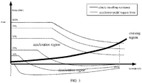
- FIG. 3 shows a schematic diagram of the deceleration controlling according to an embodiment of the present disclosure.
- the vertical coordinate represents the electric-motor torque (Torque)
- the horizontal coordinate represents the vehicle speed (Speed).
- Step 211 calculating a second torque difference between the deceleration controlling torque and the second electric-motor recovering torque.
- the entire-vehicle controller of the vehicle subtracts the deceleration controlling torque and the second electric-motor recovering torque, to obtain the difference between them, i.e., to obtain the second torque difference, and sends the difference to the hydraulic braking system of the vehicle to execute the step 212.
- Step 212 performing pressure buildup to the vehicle based on the second torque difference, to control the vehicle to complete a decelerating operation.
- the hydraulic braking system of the vehicle builds up the liquid pressure with the second torque difference as the controlling target, thereby providing the braking force to the entire vehicle to realize the braking, i.e., controlling the vehicle to complete the decelerating operation.
- FIG. 4 shows a schematic diagram of the principle of the one-pedal brake-stopping according to an embodiment of the present disclosure.
- the horizontal axis represents the vehicle speed (Vehicle Speed), and the longitudinal axis represents the torque (Torque).
- the vehicle speed and the torque are calibration quantities, and may be adaptively calibrated according to different demands.
- the parking method includes, when the vehicle satisfies a one-pedal activating condition, controlling the vehicle to enter a one-pedal-function activating mode; when the vehicle enters the one-pedal-function activating mode and satisfies a parking-controlling-function activating condition, acquiring current-vehicle-speed information, road-slope information and a first electric-motor recovering torque; based on the current-vehicle-speed information and the road-slope information, calculating to obtain a parking torque; acquiring a first torque difference between the parking torque and the first electric-motor recovering torque; performing pressure buildup to the vehicle based on the first torque difference, to control the vehicle to complete a parking operation; when the vehicle enters the one-pedal-function activating mode and satisfies a vehicle-stabilization-controlling-function activating condition, generating a hydraulic-compensation increasing instruction; in response to the hydraulic-compensation increasing instruction, controlling the vehicle to complete a vehicle stabilizing
- the vehicle may also perform braking compensation to the vehicle by means of the pressure buildup, to control the vehicle to complete the brake-stopping, which can improve the effect of the brake-stopping of the vehicle, and ensure the drive uniformity.
- FIG. 5 shows a schematic structural diagram of the parking apparatus according to the third embodiment of the present disclosure.
- the parking apparatus may be applied to a vehicle having a hydraulic braking system.
- the parking apparatus 300 may particularly include:
- the apparatus further includes:
- the apparatus further includes:
- the apparatus further includes:
- the hydraulic-compensation increasing instruction includes an instruction for increasing a hydraulic braking force, wherein the hydraulic braking force enables the vehicle to stop within a preset slope range.
- the parking apparatus can, by using the first controlling module, when the vehicle satisfies a one-pedal activating condition, control the vehicle to enter a one-pedal-function activating mode; subsequently, by using the first acquiring module, when the vehicle enters the one-pedal-function activating mode and satisfies a parking-controlling-function activating condition, acquire current-vehicle-speed information, road-slope information and a first electric-motor recovering torque; by using the first calculating module, based on the current-vehicle-speed information and the road-slope information, calculate to obtain a parking torque; by using the second acquiring module, acquire a first torque difference between the parking torque and the first electric-motor recovering torque; and by using the second controlling module, perform pressure buildup to the vehicle based on the first torque difference.
- the vehicle may also perform braking compensation to the vehicle by means of the pressure buildup, to control the vehicle to complete the parking operation, i.e., to enable the vehicle to complete the brake-stopping, which can improve the effect of the brake-stopping of the vehicle, and ensure the drive uniformity.
- the above-described device embodiments are merely illustrative, wherein the units that are described as separate components may or may not be physically separate, and the components that are displayed as units may or may not be physical units; in other words, they may be located at the same one location, and may also be distributed to a plurality of network units. Some or all of the modules may be selected according to the actual demands to realize the purposes of the solutions of the embodiments. A person skilled in the art can understand and execute the technical solutions without paying creative work.
- Each component embodiment of the present disclosure may be implemented by hardware, or by software modules that are operated on one or more processors, or by a combination thereof.
- a person skilled in the art should understand that some or all of the functions of some or all of the components of the computing and processing device according to the embodiments of the present disclosure may be implemented by using a microprocessor or a digital signal processor (DSP) in practice.
- DSP digital signal processor
- the present disclosure may also be implemented as apparatus or device programs (for example, computer programs and computer program products) for implementing part of or the whole of the method described herein.
- Such programs for implementing the present disclosure may be stored in a computer-readable medium, or may be in the form of one or more signals. Such signals may be downloaded from an Internet website, or provided on a carrier signal, or provided in any other forms.
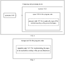
- FIG. 6 shows a computing and processing device that can execute the method according to the present disclosure.
- the computing and processing device traditionally includes a processor 1010 and a computer program product or computer-readable medium in the form of a memory 1020.
- the memory 1020 may be electronic memories such as flash memory, EEPROM (Electrically Erasable Programmable Read Only Memory), EPROM, hard disk or ROM.
- the memory 1020 has the storage space 1030 of the program code 1031 for implementing any steps of the above method.
- the storage space 1030 for program code may contain program codes 1031 for individually implementing each of the steps of the above method. Those program codes may be read from one or more computer program products or be written into the one or more computer program products.
- Those computer program products include program code carriers such as a hard disk, a compact disk (CD), a memory card or a floppy disk. Such computer program products are usually portable or fixed storage units as shown in FIG. 7 .
- the storage unit may have storage segments or storage spaces with similar arrangement to the memory 1020 of the computing and processing device in FIG. 6 .
- the program codes may, for example, be compressed in a suitable form.
- the storage unit contains a computer-readable code 1031', which can be read by a processor like 1010. When those codes are executed by the computing and processing device, the codes cause the computing and processing device to execute each of the steps of the method described above.
- any reference signs between parentheses should not be construed as limiting the claims.
- the word “comprise” does not exclude elements or steps that are not listed in the claims.
- the word “a” or “an” preceding an element does not exclude the existing of a plurality of such elements.
- the present disclosure may be implemented by means of hardware comprising several different elements and by means of a properly programmed computer. In unit claims that list several devices, some of those devices may be embodied by the same item of hardware.
- the words first, second, third and so on do not denote any order. Those words may be interpreted as names.
Landscapes
- Engineering & Computer Science (AREA)
- Transportation (AREA)
- Mechanical Engineering (AREA)
- Power Engineering (AREA)
- Physics & Mathematics (AREA)
- Electromagnetism (AREA)
- Regulating Braking Force (AREA)
- Electric Propulsion And Braking For Vehicles (AREA)
Applications Claiming Priority (2)
| Application Number | Priority Date | Filing Date | Title |
|---|---|---|---|
| CN202010048724.9A CN112297861B (zh) | 2020-01-16 | 2020-01-16 | 一种停车方法及装置 |
| PCT/CN2021/071486 WO2021143723A1 (zh) | 2020-01-16 | 2021-01-13 | 一种停车方法及装置 |
Publications (2)
| Publication Number | Publication Date |
|---|---|
| EP4067155A1 true EP4067155A1 (de) | 2022-10-05 |
| EP4067155A4 EP4067155A4 (de) | 2023-02-08 |
Family
ID=74336707
Family Applications (1)
| Application Number | Title | Priority Date | Filing Date |
|---|---|---|---|
| EP21741762.5A Pending EP4067155A4 (de) | 2020-01-16 | 2021-01-13 | Parkverfahren und -vorrichtung |
Country Status (4)
| Country | Link |
|---|---|
| US (1) | US12145451B2 (de) |
| EP (1) | EP4067155A4 (de) |
| CN (1) | CN112297861B (de) |
| WO (1) | WO2021143723A1 (de) |
Cited By (1)
| Publication number | Priority date | Publication date | Assignee | Title |
|---|---|---|---|---|
| EP4231812B1 (de) * | 2021-09-18 | 2026-03-25 | Nanjing Chervon Industry Co., Ltd. | Rasenmäher |
Families Citing this family (19)
| Publication number | Priority date | Publication date | Assignee | Title |
|---|---|---|---|---|
| US11981309B2 (en) * | 2020-09-28 | 2024-05-14 | Ford Global Technologies, Llc | Brake assist during vehicle one pedal drive |
| CN112758108A (zh) * | 2021-03-11 | 2021-05-07 | 蔚来汽车科技(安徽)有限公司 | 自动驾驶控制方法、自动驾驶控制系统和车辆 |
| CN114013408B (zh) * | 2021-09-28 | 2024-05-07 | 上海汽车制动系统有限公司 | 一种电子鼓式制动系统的驻车夹紧力衰减补偿方法 |
| CN113830043B (zh) * | 2021-10-14 | 2023-12-15 | 奇瑞新能源汽车股份有限公司 | 车辆的制动点头优化方法、装置、车辆及存储介质 |
| US12024026B2 (en) * | 2022-04-28 | 2024-07-02 | GM Global Technology Operations LLC | One pedal driving system for an electric vehicle with active zone notification |
| CN114872671B (zh) * | 2022-06-20 | 2023-03-31 | 北京京深深向科技有限公司 | 一种车辆临停制动控制系统、车辆和其控制方法 |
| CN114889567B (zh) * | 2022-06-29 | 2023-05-23 | 重庆长安新能源汽车科技有限公司 | 一种汽车辅助驻车控制方法、系统、设备、介质及程序 |
| CN115009239B (zh) * | 2022-07-07 | 2023-11-07 | 浙江极氪智能科技有限公司 | 车辆的驻停方法、装置、设备及存储介质 |
| CN115416494B (zh) * | 2022-07-29 | 2024-07-02 | 上海伊控动力系统有限公司 | 一种电动汽车单踏板停车控制方法 |
| CN115416666A (zh) * | 2022-09-02 | 2022-12-02 | 长城汽车股份有限公司 | 手势控车方法、装置、车辆及存储介质 |
| CN115503494B (zh) * | 2022-10-27 | 2025-06-27 | 长城汽车股份有限公司 | 单踏板车辆的控制方法、车辆控制终端及单踏板车辆 |
| CN115837844B (zh) * | 2022-12-16 | 2026-03-17 | 河南科技大学 | 一种单踏板电动直驱车辆控制方法 |
| CN116215531B (zh) * | 2022-12-30 | 2026-03-17 | 芜湖阿尔特动力科技有限公司 | 车辆坡道驻停的控制方法、装置、电子设备及存储介质 |
| CN116039594B (zh) * | 2023-03-06 | 2024-07-02 | 广州汽车集团股份有限公司 | 车辆的液压制动控制方法、装置、设备及存储介质 |
| US12384246B2 (en) | 2023-03-22 | 2025-08-12 | Ford Global Technologies, Llc | Low-speed vehicle control |
| CN116442968B (zh) * | 2023-05-23 | 2026-01-02 | 蔚来汽车科技(安徽)有限公司 | 车辆刹停控制方法、计算机设备、存储介质及车辆 |
| CN117302126B (zh) * | 2023-11-29 | 2024-03-19 | 中国第一汽车股份有限公司 | 车辆控制方法、系统、车辆及存储介质 |
| CN118833080B (zh) * | 2024-09-23 | 2025-01-03 | 张家港长城汽车研发有限公司 | 单踏板模式下的扭矩控制方法、装置、电子设备及车辆 |
| CN119218237B (zh) * | 2024-12-03 | 2025-03-25 | 张家港长城汽车研发有限公司 | 一种车辆控制方法、装置、车辆及存储介质 |
Family Cites Families (14)
| Publication number | Priority date | Publication date | Assignee | Title |
|---|---|---|---|---|
| JP3675383B2 (ja) * | 1995-09-20 | 2005-07-27 | 三菱自動車工業株式会社 | 電気式車両の回生制動制御装置 |
| JP2001071794A (ja) * | 1999-07-01 | 2001-03-21 | Hitachi Ltd | 自動車の走行制御装置および自動車 |
| EP1792799A3 (de) | 1999-07-01 | 2008-10-22 | Hitachi, Ltd. | Vorrichtung zur Steuerung der Bremsung und der Antriebskraft eines Fahrzeugs |
| JP5692405B2 (ja) * | 2011-11-04 | 2015-04-01 | トヨタ自動車株式会社 | 車両および車両の制御方法 |
| US10836375B2 (en) | 2013-02-08 | 2020-11-17 | Cummins Electrified Power Na Inc. | Powertrain configurations for single-motor, two-clutch hybrid electric vehicles |
| KR101618453B1 (ko) * | 2014-10-29 | 2016-05-04 | 쌍용자동차 주식회사 | 전기동력자동차의 원-페달 운전제어방법 |
| JP6073941B2 (ja) | 2015-02-18 | 2017-02-01 | 本田技研工業株式会社 | 車両用走行制御装置 |
| RU2693424C1 (ru) * | 2015-11-09 | 2019-07-02 | Ниссан Мотор Ко., Лтд. | Способ управления тормозной/движущей силой и устройство управления тормозной/движущей силой |
| RU2699204C1 (ru) * | 2015-11-09 | 2019-09-03 | Ниссан Мотор Ко., Лтд. | Способ управления тормозной/движущей силой и устройство управления тормозной/движущей силой |
| JP6769279B2 (ja) | 2016-12-13 | 2020-10-14 | 日産自動車株式会社 | 電動車両の制動制御方法、及び電動車両の制御装置 |
| CN108909711B (zh) * | 2018-06-07 | 2020-08-04 | 北京车和家信息技术有限公司 | 车辆及其控制方法、控制装置和计算机可读存储介质 |
| CN109130887A (zh) * | 2018-09-20 | 2019-01-04 | 北京新能源汽车股份有限公司 | 一种电制动补偿控制方法、控制装置及汽车 |
| CN109515200A (zh) * | 2018-11-30 | 2019-03-26 | 北京新能源汽车股份有限公司 | 车辆及单踏板电动汽车的再生制动控制方法和装置 |
| CN110605971B (zh) * | 2019-09-17 | 2020-12-01 | 中国第一汽车股份有限公司 | 电动汽车坡道驻车控制方法、控制系统及电动汽车 |
-
2020
- 2020-01-16 CN CN202010048724.9A patent/CN112297861B/zh active Active
-
2021
- 2021-01-13 US US17/790,312 patent/US12145451B2/en active Active
- 2021-01-13 WO PCT/CN2021/071486 patent/WO2021143723A1/zh not_active Ceased
- 2021-01-13 EP EP21741762.5A patent/EP4067155A4/de active Pending
Cited By (1)
| Publication number | Priority date | Publication date | Assignee | Title |
|---|---|---|---|---|
| EP4231812B1 (de) * | 2021-09-18 | 2026-03-25 | Nanjing Chervon Industry Co., Ltd. | Rasenmäher |
Also Published As
| Publication number | Publication date |
|---|---|
| EP4067155A4 (de) | 2023-02-08 |
| CN112297861A (zh) | 2021-02-02 |
| US12145451B2 (en) | 2024-11-19 |
| WO2021143723A1 (zh) | 2021-07-22 |
| CN112297861B (zh) | 2022-07-12 |
| US20230050845A1 (en) | 2023-02-16 |
Similar Documents
| Publication | Publication Date | Title |
|---|---|---|
| EP4067155A1 (de) | Parkverfahren und -vorrichtung | |
| CN114802137B (zh) | 制动衰退补偿方法、装置、电子设备及计算机存储介质 | |
| CN111422173B (zh) | 一种自动驻车方法、装置及存储介质 | |
| US12043259B2 (en) | Method and device for parking control, vehicle controller, and new-energy vehicle | |
| CN112373455A (zh) | 汽车电机制动方法、装置、设备及存储介质 | |
| EP4559728A1 (de) | Unterstütztes steuerungsverfahren und -system zur verhinderung des zurückrollens eines elektrofahrzeugs und fahrzeug | |
| CN113365870A (zh) | 电动车辆的控制装置、控制方法以及控制系统 | |
| CN113147753B (zh) | 车辆制动控制方法、装置、存储介质及自动制动系统 | |
| CN111942356A (zh) | 一种驻车方法、装置、系统及终端 | |
| KR102163963B1 (ko) | 자동차의 페달 답력 제어 시스템 및 방법 | |
| US10179578B2 (en) | Method for controlling braking of vehicle to prevent jerk when parking or stopping vehicle | |
| CN112896165B (zh) | 车辆控制方法及装置、车辆 | |
| CN118545006A (zh) | 用于车辆的回馈制动防抱死控制方法、装置、系统和车辆 | |
| CN113815429B (zh) | 整车扭矩限制方法、车辆及计算机可读存储介质 | |
| US20160052521A1 (en) | Apparatus and method for controlling distribution of braking force of vehicle | |
| CN112590564B (zh) | 电机扭矩的控制方法、装置、电子设备以及存储介质 | |
| CN112776787B (zh) | 一种车辆紧急制动控制方法、装置及计算机存储介质 | |
| US20230139991A1 (en) | Pure electric available power determination method and system, and vehicle | |
| EP4403400A1 (de) | Verfahren zum steuern einer verzögerungsanforderung in einem einpedal-fahrmodus eines fahrzeugs, datenverarbeitungsvorrichtung, computerprogramm, computerlesbares speichermedium, antriebsstrang für ein fahrzeug und fahrzeug | |
| EP4470859B1 (de) | Verfahren zur steuerung einer verzögerungsanforderung in einem einpedal-fahrmodus eines fahrzeugs, computerprogrammprodukt, datenverarbeitungsvorrichtung und fahrzeug | |
| CN110834612A (zh) | 冗余制动控制方法、装置、系统、车辆和存储介质 | |
| CN118254601B (zh) | 用于电动汽车的控制方法、装置、电动汽车 | |
| CN115782602A (zh) | 电动车辆能量回收控制方法、装置及电动车辆 | |
| WO2022196513A1 (ja) | 駆動システム | |
| CN113815430A (zh) | 辅助驾驶的控制方法、车辆及计算机可读存储介质 |
Legal Events
| Date | Code | Title | Description |
|---|---|---|---|
| STAA | Information on the status of an ep patent application or granted ep patent |
Free format text: STATUS: THE INTERNATIONAL PUBLICATION HAS BEEN MADE |
|
| PUAI | Public reference made under article 153(3) epc to a published international application that has entered the european phase |
Free format text: ORIGINAL CODE: 0009012 |
|
| STAA | Information on the status of an ep patent application or granted ep patent |
Free format text: STATUS: REQUEST FOR EXAMINATION WAS MADE |
|
| 17P | Request for examination filed |
Effective date: 20220627 |
|
| AK | Designated contracting states |
Kind code of ref document: A1 Designated state(s): AL AT BE BG CH CY CZ DE DK EE ES FI FR GB GR HR HU IE IS IT LI LT LU LV MC MK MT NL NO PL PT RO RS SE SI SK SM TR |
|
| A4 | Supplementary search report drawn up and despatched |
Effective date: 20230109 |
|
| RIC1 | Information provided on ipc code assigned before grant |
Ipc: B60K 26/02 19740701ALI20230102BHEP Ipc: B60T 7/06 19680901ALI20230102BHEP Ipc: B60T 1/10 19680901ALI20230102BHEP Ipc: B60W 30/18 20060101ALI20230102BHEP Ipc: B60W 30/00 20060101ALI20230102BHEP Ipc: B60L 15/20 19680901ALI20230102BHEP Ipc: B60L 7/26 19680901AFI20230102BHEP |
|
| DAV | Request for validation of the european patent (deleted) | ||
| DAX | Request for extension of the european patent (deleted) |