EP4066604B1 - Frequenzumrichter-baureihe - Google Patents
Frequenzumrichter-baureihe Download PDFInfo
- Publication number
- EP4066604B1 EP4066604B1 EP20812324.0A EP20812324A EP4066604B1 EP 4066604 B1 EP4066604 B1 EP 4066604B1 EP 20812324 A EP20812324 A EP 20812324A EP 4066604 B1 EP4066604 B1 EP 4066604B1
- Authority
- EP
- European Patent Office
- Prior art keywords
- frequency converter
- type
- housing element
- housing
- frequency
- Prior art date
- Legal status (The legal status is an assumption and is not a legal conclusion. Google has not performed a legal analysis and makes no representation as to the accuracy of the status listed.)
- Active
Links
Images
Classifications
-
- H—ELECTRICITY
- H05—ELECTRIC TECHNIQUES NOT OTHERWISE PROVIDED FOR
- H05K—PRINTED CIRCUITS; CASINGS OR CONSTRUCTIONAL DETAILS OF ELECTRIC APPARATUS; MANUFACTURE OF ASSEMBLAGES OF ELECTRICAL COMPONENTS
- H05K5/00—Casings, cabinets or drawers for electric apparatus
- H05K5/06—Hermetically-sealed casings
- H05K5/061—Hermetically-sealed casings sealed by a gasket held between a removable cover and a body, e.g. O-ring, packing
-
- H—ELECTRICITY
- H05—ELECTRIC TECHNIQUES NOT OTHERWISE PROVIDED FOR
- H05K—PRINTED CIRCUITS; CASINGS OR CONSTRUCTIONAL DETAILS OF ELECTRIC APPARATUS; MANUFACTURE OF ASSEMBLAGES OF ELECTRICAL COMPONENTS
- H05K7/00—Constructional details common to different types of electric apparatus
- H05K7/14—Mounting supporting structure in casing or on frame or rack
- H05K7/1422—Printed circuit boards receptacles, e.g. stacked structures, electronic circuit modules or box like frames
- H05K7/1427—Housings
- H05K7/1432—Housings specially adapted for power drive units or power converters
- H05K7/14324—Housings specially adapted for power drive units or power converters comprising modular units, e.g. DIN rail mounted units
Definitions
- the invention relates to a frequency converter series with different types of frequency converters.
- the WO 2004/026013 A1 discloses a frequency converter series according to the preamble of claim 1.
- the invention is based on the object of providing a frequency converter series with different types of frequency converters which can be manufactured easily and cost-effectively and which enables a high degree of flexibility.
- the frequency converter series includes different types of frequency converters
- a first type of frequency converter of the frequency converter series has the following components: a power electronics unit, for example comprising a three-phase inverter, a carrier element and a housing element of a first housing element type, which in conjunction with the carrier element forms a housing for the power electronics.
- a power electronics unit for example comprising a three-phase inverter, a carrier element and a housing element of a first housing element type, which in conjunction with the carrier element forms a housing for the power electronics.
- a second type of frequency converter in the frequency converter series also has the same type of power electronics and the same type of carrier element as the first type of frequency converter. In this respect, there are no differences between the first type and the second type.
- the second type of frequency converter in the frequency converter series differs from the first type of frequency converter in the frequency converter series by its housing element of a second housing element type, which in conjunction with the carrier element forms a housing for the power electronics.
- the housing element of the first housing element type is designed such that the frequency converter of the first type has a first degree of protection.
- the housing element of the second housing element type is designed such that the frequency converter of the second type has a second degree of protection that is different from the first degree of protection.
- the first housing element type can have identical dimensions to the second housing element type, i.e. an identical length, width, height, etc.
- the first degree of protection is IP 66 according to IEC 60 529 (EN 60 529).
- the housing element of the first housing element type can be designed to be closed and can, for example, have circumferential seals arranged between the housing element and the carrier element.
- the second protection class can be IP 31, for example.
- the housing element of the first housing element type in particular in conjunction with the carrier element, forms a first volume and the housing element of the second housing element type, in particular in conjunction with the carrier element, forms a second volume different from the first volume.
- a third type of frequency converter in the frequency converter series has the same type of power electronics and the same type of carrier element as the first type of frequency converter and the second type of frequency converter. In this respect, there are no differences between the first type, the second type and the third type.
- the third type of frequency converter in the frequency converter series differs from the first type or second type of frequency converter in the frequency converter series by its housing element of a third housing element type, which in conjunction with the carrier element forms a housing for the power electronics.
- the housing element of the first housing element type is designed such that the frequency converter of the first type has a first protection class, for example IP 66.
- the housing element of the second housing element type is designed such that the frequency converter of the second type has a second protection class different from the first protection class, for example IP 31.
- the housing element of the third housing element type forms a volume that is different from a volume that the first housing element type forms and/or that the second housing element type forms.
- the first type, the second type and the third type of frequency converters of the frequency converter series have a removable cover element by means of which a connection compartment of the frequency converter can be opened and closed again. Connections of the respective frequency converters can be arranged in the connection compartment, regardless of type, via which the respective frequency converter can be electrically connected, for example, to a three-phase motor, sensors, encoders, an intermediate circuit, a three-phase network, etc.
- the first type and the second type of frequency converters of the frequency converter series can have an identical cover element.
- the cover element is wedge-shaped in order to allow as unhindered access as possible to the connection space when the cover element is removed or opened.
- only one type, in particular the third type, of frequency converters of the frequency converter series has a mains disconnector which, depending on the switching state, connects or disconnects the corresponding type of frequency converter to or from a three-phase network.
- the carrier element forms a heat sink, in particular made of metal, in particular in the form of a cast body.
- the heat sink can have cooling fins on its side facing away from the housing element.
- the heat sink serves in particular to cool the power electronics and is preferably connected to them in a heat-conducting manner.
- the carrier element has fastening means by means of which a respective frequency converter can be mechanically detachably fastened to a designated mounting location, for example on a rail in a control cabinet or within a system or on a building wall.
- the first type, the second type and the third type of frequency converters of the frequency converter series have a trough-shaped receiving recess and an interface arranged in the receiving recess, wherein a frequency converter-external control device can be inserted in the receiving recess, which can be coupled to the respective frequency converter via the interface for data exchange.
- the control device can be, for example, a parameterization device, a WLAN module, etc.
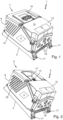
- Fig. 1 shows a perspective view of a frequency converter 1 of a first type of a frequency converter series.
- the first type of frequency converter in the frequency converter series consists of a power electronics unit 4, for example a three-phase inverter, a carrier element 5 made of metal, which simultaneously forms a heat sink, and a housing element 6 of a first housing element type, which in conjunction with the carrier element 5 forms a housing 7 for the power electronics unit 4.
- a power electronics unit 4 for example a three-phase inverter
- a carrier element 5 made of metal, which simultaneously forms a heat sink
- a housing element 6 of a first housing element type which in conjunction with the carrier element 5 forms a housing 7 for the power electronics unit 4.
- the frequency converter 1 has a protection class according to IP 66.
- the frequency converter 1 has a removable wedge-shaped cover element 12, by means of which a connection compartment 19 of the frequency converter 1 can be closed. When the cover element 12 is removed, connections of the frequency converter 1 are accessible so that, for example, cables that are led into the connection compartment 19 via cable feed openings 18 can be connected to the connections.
- the carrier element 5 has fastening means 17, by means of which the frequency converter 1 can be mechanically detachably fastened to a designated mounting location.
- An external control device 16 in the form of a parameterization device is inserted into a receiving recess 14 formed in the housing element 6, in which an interface 15 of the frequency converter 1 is arranged, which is coupled to the frequency converter 1 for data exchange via the interface 15, see also Fig. 2 .
- Fig. 2 shows a perspective view of a frequency converter 2 of a second type of the frequency converter series, for descriptive reasons without an external control unit 16 inserted into the receiving recess 14.
- the frequency converter 2 of the second type preferably differs from the frequency converter 1 of the first type only in its housing element 8 or housing 9, which has strip-shaped openings 20, whereas the housing element 6 has closed slats 21.
- a respective longitudinal extension of the strip-shaped openings 10 or the slats 21 in the intended installation orientation of the frequency converter 1 or 2 forms an angle of approximately 25 degrees to the horizontal.
- the frequency converter 2 of the second type has a protection class according to IP 31, whereas the frequency converter 1 of the first type has a protection class according to IP 66.
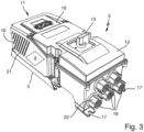
- Fig. 3 shows a perspective view of a frequency converter 3 of a third type of the frequency converter series.
- the frequency converter 3 of the third type differs from the frequency converters 1 and 2 of the first and second types, respectively, by its housing element 10 and its housing 11, which has a different volume than the housing elements 6 and 8 of the same volume.
- frequency converter 3 has a mains disconnect switch 13 for disconnecting from the mains.
- Frequency converter 3 can have a protection class according to IP 66.
- further openings can preferably be broken out of the housing elements 6, 8 and 10 in order to be able to lead other types of cables into the housing.
- mains and motor connection openings can be present.
- the housing elements 6, 8, 10 are releasably attached to the support element 5, for example by means of screws.
- the cover element 12 can also be releasably attached to the housing elements 6, 8, 10 by means of screws.
- the frequency converter series according to the invention has a high degree of identical parts with identical power electronics and carrier element. The only differences are essentially in the various housing elements by means of which the frequency converters are differentiated or standardized. This enables cost-effective production and storage while at the same time providing a high level of flexibility.
- the cable feed openings 18 can be closed with the corresponding sealing plugs 22 in order to achieve the necessary fluid tightness or protection class.
- the sealing plugs 22 can also be used in conjunction with the Fig. 1 shown embodiment can be used.
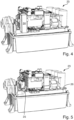
- Fig. 4 shows a perspective view of a frequency converter 23 of the first, second or third type with the housing element 6, 8 or 10 removed.
- the frequency converter 23 has a circuit board 26 on which a safety module 24 is plugged.
- the plugged safety module 24 causes the frequency converter 23 to fulfill certain requirements of functional safety.
- Fig. 5 shows a perspective view of the frequency converter 23 of Fig. 4 without the safety module 24 plugged in, which changes the behavior of the frequency converter 23 with regard to functional safety.
- the board 26 has tabs 25 onto which the safety module 24 is connected, as shown in Fig. 4 shown, can be plugged on.
- the power electronics 4 can be arranged on the circuit board 26.
Landscapes
- Engineering & Computer Science (AREA)
- Microelectronics & Electronic Packaging (AREA)
- Inverter Devices (AREA)
Description
- Die Erfindung betrifft eine Frequenzumrichter-Baureihe mit unterschiedlichen Typen von Frequenzumrichtern.
- Die
WO 2004/026013 A1 offenbart eine Frequenzumrichter-Baureihe gemäß dem Oberbegriff des Anspruchs 1. - Der Erfindung liegt die Aufgabe zugrunde, eine Frequenzumrichter-Baureihe mit unterschiedlichen Typen von Frequenzumrichtern zur Verfügung zu stellen, die einfach und kostengünstig herstellbar ist und die eine hohe Flexibilität ermöglicht.
- Diese Aufgabe wird durch eine Frequenzumrichter-Baureihe gemäss Anspruch 1 gelöst. Weitere Ausführungsbeispiele sind den abhängigen Ansprüchen zu entnehmen.
- Die Frequenzumrichter-Baureihe umfasst unterschiedliche Typen von Frequenzumrichtern
- Ein erster Typ von Frequenzumrichtern der Frequenzumrichter-Baureihe weist folgende Komponenten auf: eine Leistungselektronik, beispielsweise aufweisend einen dreiphasigen Wechselrichter, ein Trägerelement und ein Gehäuseelement eines ersten Gehäuseelement-Typs, das in Verbindung mit dem Trägerelement ein Gehäuse für die Leistungselektronik bildet.
- Ein zweiter Typ von Frequenzumrichtern der Frequenzumrichter-Baureihe weist als Gleichteile zum ersten Typ von Frequenzumrichtern ebenfalls die typgleiche Leistungselektronik und das typgleiche Trägerelement auf. Insoweit gibt es zwischen dem ersten Typ und dem zweiten Typ keine Unterschiede. Der zweite Typ von Frequenzumrichtern der Frequenzumrichter-Baureihe unterscheidet sich vom ersten Typ von Frequenzumrichtern der Frequenzumrichter-Baureihe durch sein Gehäuseelement eines zweiten Gehäuseelement-Typs, das in Verbindung mit dem Trägerelement ein Gehäuse für die Leistungselektronik bildet.
- Das Gehäuseelement des ersten Gehäuseelement-Typs ist derart gestaltet, dass der Frequenzumrichter des ersten Typs eine erste Schutzart aufweist. Das Gehäuseelement des zweiten Gehäuseelement-Typs ist derart gestaltet, dass der Frequenzumrichter des zweiten Typs eine zweite, von der ersten Schutzart verschiedene Schutzart aufweist. Der erste Gehäuseelement-Typ kann identische Abmessungen aufweisen wie der zweite Gehäuseelement-Typ, also eine identische Länge, Breite, Höhe usw.
- Gemäß einer Ausführungsform ist die erste Schutzart IP 66 gemäß IEC 60 529 (EN 60 529). Hierzu kann das Gehäuseelement des ersten Gehäuseelement-Typs geschlossen ausgeführt sein und beispielsweise umlaufende Dichtungen aufweisen, die zwischen Gehäuseelement und Trägerelement angeordnet sind. Die zweite Schutzart kann beispielsweise IP 31 sein.
- Gemäß einer Ausführungsform bildet das Gehäuseelement des ersten Gehäuseelement-Typs, insbesondere in Verbindung mit dem Trägerelement, ein erstes Volumen und das Gehäuseelement des zweiten Gehäuseelement-Typs bildet, insbesondere in Verbindung mit dem Trägerelement, ein zweites, von dem ersten Volumen verschiedenes Volumen.
- Gemäß einer Ausführungsform weist ein dritter Typ von Frequenzumrichtern der Frequenzumrichter-Baureihe als Gleichteile zum ersten Typ von Frequenzumrichtern und zum zweiten Typ von Frequenzumrichtern ebenfalls die typgleiche Leistungselektronik und das typgleiche Trägerelement auf. Insofern gibt es zwischen dem ersten Typ, dem zweiten Typ und dem dritten Typ keine Unterschiede. Der dritte Typ von Frequenzumrichtern der Frequenzumrichter-Baureihe unterscheidet sich vom ersten Typ bzw. zweiten Typ von Frequenzumrichtern der Frequenzumrichter-Baureihe durch sein Gehäuseelement eines dritten Gehäuseelement-Typs, das in Verbindung mit dem Trägerelement ein Gehäuse für die Leistungselektronik bildet.
- Gemäß einer Ausführungsform ist das Gehäuseelement des ersten Gehäuseelement-Typs derart ausgebildet, dass der Frequenzumrichter des ersten Typs eine erste Schutzart aufweist, beispielsweise IP 66. Das Gehäuseelement des zweiten Gehäuseelement-Typs ist derart ausgebildet, dass der Frequenzumrichter des zweiten Typs eine zweite, von der ersten Schutzart verschiedene Schutzart aufweist, beispielswiese IP 31. Das Gehäuseelement des dritten Gehäuseelement-Typs bildet ein Volumen, das von einem Volumen verschieden ist, das der erste Gehäuseelement-Typ bildet, und/oder das der zweite Gehäuseelement-Typ bildet.
- Gemäß einer Ausführungsform weisen der erste Typ, der zweite Typ und der dritte Typ von Frequenzumrichtern der Frequenzumrichter-Baureihe ein abnehmbares Deckelelement auf, mittels dem ein Anschlussraum des Frequenzumrichters öffenbar und wieder verschließbar ist. Im Anschlussraum können typunabhängig Anschlüsse der jeweiligen Frequenzumrichter angeordnet sein, über die der jeweilige Frequenzumrichter beispielsweise mit einem Drehstrommotor, Sensoren, Gebern, einem Zwischenkreis, einem Drehstromnetz usw. elektrisch verbunden werden kann. Der erste Typ und der zweite Typ von Frequenzumrichtern der Frequenzumrichter-Baureihe können ein identisches Deckelelement aufweisen.
- Zwischen dem Trägerelement und einem Gehäuseelement eines Typs oder aller Typen ist eine formschlüssige Verbindung vorhanden. Je nach notwendiger Schutzart ist im Bereich der formschlüssigen Verbindung eine Dichtung vorgesehen.
- Gemäß einer Ausführungsform ist das Deckelelement keilförmig ausgebildet, um bei abgenommenem bzw. geöffnetem Deckelelement einen möglichst ungehinderten Zugang zu dem Anschlussraum zu ermöglichen.
- Gemäß einer Ausführungsform weist nur ein Typ, insbesondere der dritte Typ, von Frequenzumrichtern der Frequenzumrichter-Baureihe einen Netztrennschalter auf, der schaltzustandsabhängig den entsprechenden Typ von Frequenzumrichter mit einem Drehstromnetz verbindet bzw. von diesem trennt.
- Gemäß einer Ausführungsform bildet das Trägerelement einen Kühlkörper, insbesondere aus Metall, insbesondere in Form eines Gusskörpers. Der Kühlkörper kann auf seiner vom Gehäuseelement abgewandten Seite Kühlrippen aufweisen. Der Kühlkörper dient insbesondere zur Kühlung der Leistungselektronik und ist mit dieser bevorzugt wärmeleitend verbunden.
- Gemäß einer Ausführungsform weist das Trägerelement Befestigungsmittel auf, mittels derer ein jeweiliger Frequenzumrichter mechanisch lösbar an einem vorgesehenen Anbringungsort befestigbar ist, beispielsweise auf einer Schiene in einem Schaltschrank oder innerhalb einer Anlage oder an einer Gebäudewand.
- Gemäß einer Ausführungsform weisen der erste Typ, der zweite Typ und der dritte Typ von Frequenzumrichtern der Frequenzumrichter-Baureihe eine wannenförmige Aufnahmemulde und eine in der Aufnahmemulde angeordnete Schnittstelle auf, wobei in der Aufnahmemulde ein Frequenzumrichter-externes Steuergerät einsetzbar ist, das über die Schnittstelle mit dem jeweiligen Frequenzumrichter zum Datenaustausch koppelbar ist. Das Steuergerät kann beispielsweise ein Parametriergerät, ein WLAN-Modul usw. sein.
- Die Erfindung wird nachfolgend unter Bezugnahme auf die Zeichnungen detailliert beschrieben. Hierbei zeigt:
- Fig. 1
- eine perspektivische Darstellung eines Frequenzumrichters eines ersten Typs einer Frequenzumrichter-Baureihe,
- Fig. 2
- eine perspektivische Darstellung eines Frequenzumrichters eines zweiten Typs einer Frequenzumrichter-Baureihe,
- Fig. 3
- eine perspektivische Darstellung eines Frequenzumrichters eines dritten Typs einer Frequenzumrichter-Baureihe,
- Fig. 4
- eine perspektivische Darstellung eines Frequenzumrichters des ersten, zweiten oder dritten Typs bei entferntem Gehäuseelement, wobei auf einer Platine des Frequenzumrichters ein Safety-Modul gesteckt ist, und
- Fig. 5
- eine perspektivische Darstellung des Frequenzumrichters von
Fig. 4 ohne gestecktes Safety-Modul. -
Fig. 1 zeigt eine perspektivische Darstellung eines Frequenzumrichters 1 eines ersten Typs einer Frequenzumrichter-Baureihe. - Der erste Typ von Frequenzumrichter der Frequenzumrichter-Baureihe setzt sich zusammen aus einer Leistungselektronik 4, beispielsweise einem dreiphasigen Wechselrichter, einem Trägerelement 5 aus Metall, das gleichzeitig einen Kühlkörper bildet, und einem Gehäuseelement 6 eines ersten Gehäuseelement-Typs, das in Verbindung mit dem Trägerelement 5 ein Gehäuse 7 für die Leistungselektronik 4 bildet.
- Der Frequenzumrichter 1 weist eine Schutzart gemäß IP 66 auf.
- Der Frequenzumrichtern 1 weist ein abnehmbares keilförmiges Deckelelement 12 auf, mittels dem ein Anschlussraum 19 des Frequenzumrichters 1 verschließbar ist. Wenn das Deckelelement 12 abgenommen ist, sind Anschlüsse des Frequenzumrichters 1 zugänglich, so dass beispielsweise Kabel, die über Kabelzuführungsöffnungen 18 in den Anschlussraum 19 geführt sind, an die Anschlüsse angeschlossen werden können.
- Das Trägerelement 5 weist Befestigungsmittel 17 auf, mittels derer der Frequenzumrichter 1 mechanisch lösbar an einem vorgesehenen Anbringungsort befestigbar ist.
- In eine in dem Gehäuseelement 6 gebildete Aufnahmemulde 14, in der eine Schnittstelle 15 des Frequenzumrichters 1 angeordnet ist, ist ein externes Steuergerät 16 in Form einer Parametriervorrichtung eingesetzt, das über die Schnittstelle 15 mit dem Frequenzumrichter 1 zum Datenaustausch gekoppelt ist, siehe auch
Fig. 2 . -
Fig. 2 zeigt eine perspektivische Darstellung eines Frequenzumrichters 2 eines zweiten Typs der Frequenzumrichter-Baureihe, aus Beschreibungsgründen ohne ein in die Aufnahmemulde 14 eingesetztes externes Steuergerät 16. - Der Frequenzumrichter 2 des zweiten Typs unterscheidet sich bevorzugt von dem Frequenzumrichter 1 des ersten Typs nur durch sein Gehäuseelement 8 bzw. Gehäuse 9, das streifenförmige Öffnungen 20 aufweist, wohingegen das Gehäuseelement 6 geschlossene Lamellen 21 aufweist. Eine jeweilige Längserstreckung der streifenförmigen Öffnungen 10 bzw. der Lamellen 21 in der vorgesehenen Einbauausrichtung des Frequenzumrichters 1 bzw. 2 bildet einen Winkel von ca. 25 Grad zur Waagerechten.
- Der Frequenzumrichters 2 des zweiten Typs weist eine Schutzart gemäß IP 31 auf, wohingegen der Frequenzumrichters 1 des ersten Typs eine Schutzart gemäß IP 66 aufweist.
- Bei dem Frequenzumrichter 1 des ersten Typs mit Schutzart gemäß IP 66 können zum Erzielen der höheren Schutzart zusätzlich noch Dichtungen zwischen dem Gehäuseelement 6 und dem Trägerelement 5 vorgesehen sein.
-
Fig. 3 zeigt eine perspektivische Darstellung eines Frequenzumrichters 3 eines dritten Typs der Frequenzumrichter-Baureihe. - Der Frequenzumrichter 3 des dritten Typs unterscheidet sich von den Frequenzumrichtern 1 und 2 des ersten bzw. zweiten Typs unter anderem durch sein Gehäuseelement 10 bzw. sein Gehäuse 11, das ein anderes Volumen aufweist als die gleichvolumigen Gehäuseelemente 6 und 8.
- Der Frequenzumrichter 3 weist anders als die Frequenzumrichter 1 und 2 einen Netztrennschalter 13 zur Netztrennung auf. Der Frequenzumrichter 3 kann eine Schutzart gemäß IP 66 aufweisen.
- Zusätzlich zu den Kabelzuführungsöffnungen 18 sind bevorzugt weitere Öffnungen aus den Gehäuseelementen 6, 8 und 10 ausbrechbar, um weitere Kabeltypen ins Gehäuse führen zu können. Standardmäßig können beispielsweise nur Netz- und Motoranschluss-Öffnungen vorhanden sein.
- Die Gehäuseelemente 6, 8, 10 sind beispielsweise mittels Schrauben am Trägerelement 5 lösbar befestigt.
- Das Deckelelement 12 kann ebenfalls mittels Schrauben an den Gehäuseelementen 6, 8, 10 lösbar befestigt sein.
- Die erfindungsgemäße Frequenzumrichter-Baureihe weist eine hohe Gleichteileübereinstimmung mit identischer Leistungselektronik und Trägerelement auf. Unterschiede bestehen im Kern lediglich in den verschiedenen Gehäuseelementen, mittels derer die Frequenzumrichter ausdifferenziert bzw. typisiert sind. Dies ermöglicht eine kostengünstige Fertigung und Lagerhaltung bei gleichzeitig hoher Flexibilität.
- Bezug nehmend auf
Fig. 3 können die Kabelzuführungsöffnungen 18 mit zugehörigen Verschlusstopfen 22 verschlossen werden, um eine notwendige Fluid-Dichtigkeit bzw. Schutzart zu erzielen. - Die Verschlusstopfen 22 können auch in Verbindung mit der in
Fig. 1 gezeigten Ausführungsform verwendet werden. -
Fig. 4 zeigt eine perspektivische Darstellung eines Frequenzumrichters 23 des ersten, zweiten oder dritten Typs bei entferntem Gehäuseelement 6, 8 bzw. 10. Der Frequenzumrichter 23 weist eine Platine 26 auf, auf der ein Safety-Modul 24 gesteckt ist. Das gesteckte Safety-Modul 24 bewirkt, dass der Frequenzumrichter 23 bestimmte Voraussetzungen der funktionalen Sicherheit erfüllt. -
Fig. 5 zeigt eine perspektivische Darstellung des Frequenzumrichters 23 vonFig. 4 ohne gestecktes Safety-Modul 24, wodurch sich das Verhalten des Frequenzumrichters 23 im Hinblick auf die funktionale Sicherheit verändert. - Wie in
Fig. 5 gezeigt, weist die Platine 26 Steckzungen 25 auf, auf die das Safety-Modul 24, wie inFig. 4 gezeigt, aufsteckbar ist. - Auf der Platine 26 kann die Leistungselektronik 4 angeordnet sein.
Claims (11)
- Frequenzumrichter-Baureihe mit unterschiedlichen Typen von Frequenzumrichtern (1, 2, 3),- wobei ein erster Typ von Frequenzumrichtern (1) der Frequenzumrichter-Baureihe zusammengesetzt ist aus:- einer Leistungselektronik (4),- einem Trägerelement (5) und- einem Gehäuseelement (6) eines ersten Gehäuseelement-Typs, das in Verbindung mit dem Trägerelement (5) ein Gehäuse (7) für die Leistungselektronik (4) bildet, und- wobei ein zweiter Typ von Frequenzumrichtern (2) der Frequenzumrichter-Baureihe zusammengesetzt ist aus:- der Leistungselektronik (4),- dem Trägerelement (5) und- einem Gehäuseelement (8) eines zweiten Gehäuseelement-Typs, das in Verbindung mit dem Trägerelement (5) ein Gehäuse (9) für die Leistungselektronik (4) bildet,dadurch gekennzeichnet, dass- das Gehäuseelement (6) des ersten Gehäuseelement-Typs derart ausgebildet ist, dass der Frequenzumrichter (1) des ersten Typs eine erste Schutzart aufweist,- das Gehäuseelement (8) des zweiten Gehäuseelement-Typs derart ausgebildet ist, dass der Frequenzumrichter (2) des zweiten Typs eine zweite, von der ersten Schutzart verschiedene Schutzart aufweist, und- zwischen dem Trägerelement (5) und dem Gehäuseelement (6) des ersten Gehäuseelement-Typs und zwischen dem Trägerelement (5) und dem Gehäuseelement (8) des zweiten Gehäuseelement-Typs jeweils eine formschlüssige Verbindung vorhanden ist,- wobei je nach notwendiger Schutzart im Bereich der formschlüssigen Verbindung eine Dichtung vorgesehen ist.
- Frequenzumrichter-Baureihe nach Anspruch 1, dadurch gekennzeichnet, dass- die erste Schutzart IP 66 ist und- die zweite Schutzart IP 31 ist.
- Frequenzumrichter-Baureihe nach Anspruch 1, dadurch gekennzeichnet, dass- das Gehäuseelement (6) des ersten Gehäuseelement-Typs ein erstes Volumen bildet und- das Gehäuseelement (8) des zweiten Gehäuseelement-Typs ein zweites, von dem ersten Volumen verschiedenes Volumen bildet.
- Frequenzumrichter-Baureihe nach Anspruch 1, dadurch gekennzeichnet, dass- ein dritter Typ von Frequenzumrichtern (3) der Frequenzumrichter-Baureihe zusammengesetzt ist aus:- der Leistungselektronik (4),- dem Trägerelement (5) und- einem Gehäuseelement (10) eines dritten Gehäuseelement-Typs, das in Verbindung mit dem Trägerelement (5) ein Gehäuse (11) für die Leistungselektronik (4) bildet.
- Frequenzumrichter-Baureihe nach Anspruch 4, dadurch gekennzeichnet, dass- das Gehäuseelement (6) des ersten Gehäuseelement-Typs derart ausgebildet ist, dass der Frequenzumrichter (1) des ersten Typs eine erste Schutzart aufweist,- das Gehäuseelement (8) des zweiten Gehäuseelement-Typs derart ausgebildet ist, dass der Frequenzumrichter (2) des zweiten Typs eine zweite, von der ersten Schutzart verschiedene Schutzart aufweist, und- das Gehäuseelement (10) des dritten Gehäuseelement-Typs ein Volumen bildet, das von einem Volumen, das der erste Gehäuseelement-Typ bildet, und/oder von einem von einem Volumen, das der zweite Gehäuseelement-Typ bildet, verschieden ist.
- Frequenzumrichter-Baureihe nach einem der vorhergehenden Ansprüche, dadurch gekennzeichnet, dass- alle Typen von Frequenzumrichtern (1, 2, 3) der Frequenzumrichter-Baureihe ein Deckelelement (12) aufweisen, mittels dem ein Anschlussraum (19) des Frequenzumrichters verschließbar ist.
- Frequenzumrichter-Baureihe nach Anspruch 6, dadurch gekennzeichnet, dass- das Deckelelement (12) keilförmig ausgebildet ist.
- Frequenzumrichter-Baureihe nach einem der vorhergehenden Ansprüche, dadurch gekennzeichnet, dass- ein Typ von Frequenzumrichtern (1, 2, 3) der Frequenzumrichter-Baureihe einen Netztrennschalter (13) aufweist.
- Frequenzumrichter-Baureihe nach einem der vorhergehenden Ansprüche, dadurch gekennzeichnet, dass- das Trägerelement (5) einen Kühlkörper bildet.
- Frequenzumrichter-Baureihe nach einem der vorhergehenden Ansprüche, dadurch gekennzeichnet, dass- das Trägerelement (5) Befestigungsmittel (17) aufweist, mittels derer ein jeweiliger Frequenzumrichter (1, 2, 3) mechanisch lösbar an einem vorgesehenen Anbringungsort befestigbar ist.
- Frequenzumrichter-Baureihe nach einem der vorhergehenden Ansprüche, dadurch gekennzeichnet, dass- alle Typen von Frequenzumrichtern (1, 2, 3) der Frequenzumrichter-Baureihe eine Aufnahmemulde (14) und eine in der Aufnahmemulde (14) angeordnete Schnittstelle (15) aufweisen, wobei in der Aufnahmemulde (14) ein externes Steuergerät (16) einsetzbar ist, das über die Schnittstelle (15) mit dem jeweiligen Frequenzumrichter (1, 2, 3) zum Datenaustausch koppelbar ist.
Applications Claiming Priority (2)
| Application Number | Priority Date | Filing Date | Title |
|---|---|---|---|
| DE102019218206.2A DE102019218206B4 (de) | 2019-11-25 | 2019-11-25 | Frequenzumrichter-Baureihe |
| PCT/EP2020/083389 WO2021105227A1 (de) | 2019-11-25 | 2020-11-25 | Frequenzumrichter-baureihe |
Publications (2)
| Publication Number | Publication Date |
|---|---|
| EP4066604A1 EP4066604A1 (de) | 2022-10-05 |
| EP4066604B1 true EP4066604B1 (de) | 2025-02-19 |
Family
ID=73598132
Family Applications (1)
| Application Number | Title | Priority Date | Filing Date |
|---|---|---|---|
| EP20812324.0A Active EP4066604B1 (de) | 2019-11-25 | 2020-11-25 | Frequenzumrichter-baureihe |
Country Status (5)
| Country | Link |
|---|---|
| US (1) | US12426188B2 (de) |
| EP (1) | EP4066604B1 (de) |
| CN (1) | CN115066991A (de) |
| DE (1) | DE102019218206B4 (de) |
| WO (1) | WO2021105227A1 (de) |
Families Citing this family (2)
| Publication number | Priority date | Publication date | Assignee | Title |
|---|---|---|---|---|
| DE102021120679A1 (de) * | 2021-08-09 | 2023-02-09 | Ebm-Papst Mulfingen Gmbh & Co. Kg | Modular aufgebautes Schnittstellenkonzept für einen elektrischen Antrieb |
| DE102021215015B3 (de) | 2021-12-23 | 2023-04-27 | Lenze Se | Bausatz für verschiedene Typen einer Baureihe von Frequenzumrichtern und Frequenzumrichter |
Family Cites Families (18)
| Publication number | Priority date | Publication date | Assignee | Title |
|---|---|---|---|---|
| DE4410171C1 (de) * | 1994-03-24 | 1995-04-13 | Licentia Gmbh | Baugruppe eines Automatisierungsgeräts |
| DE19813639A1 (de) * | 1998-03-27 | 1999-11-25 | Danfoss As | Leistungsmodul für einen Stromrichter |
| FI116757B (fi) * | 2000-04-28 | 2006-02-15 | Vacon Oyj | Sovitelma taajuusmuuttajassa |
| DE10332392B4 (de) * | 2002-09-10 | 2014-12-04 | Sew-Eurodrive Gmbh & Co Kg | Feldgerät mit einem Gehäuse |
| DE102008027584B3 (de) * | 2008-06-10 | 2009-12-24 | Siemens Aktiengesellschaft | Gehäuse für ein elektrisches Gerät |
| DE102011076323B4 (de) | 2011-05-24 | 2014-04-10 | Semikron Elektronik Gmbh & Co. Kg | Leistungselektronisches System mit erstem und zweitem Subsystem |
| FR2998760B1 (fr) * | 2012-11-26 | 2014-12-19 | Schneider Toshiba Inverter | Variateur de vitesse et systeme incluant une architecture pour renforcer l'etancheite du variateur de vitesse |
| DE202014004927U1 (de) | 2014-06-13 | 2015-09-15 | Wago Verwaltungsgesellschaft Mbh | Anlagenmodul mit abnehmbarem Gehäuseteil |
| CN203967911U (zh) | 2014-07-29 | 2014-11-26 | 欧瑞传动电气股份有限公司 | 驱动一体机 |
| CN203967958U (zh) | 2014-07-29 | 2014-11-26 | 欧瑞传动电气股份有限公司 | 高防护等级变频驱动装置 |
| DE102015200375B4 (de) | 2015-01-13 | 2022-12-08 | Lenze Swiss Ag | Frequenzumrichter |
| CN204442855U (zh) | 2015-01-22 | 2015-07-01 | 台安科技(无锡)有限公司 | 工控电器产品箱体与底座的防水结构 |
| DE102015119002A1 (de) * | 2015-11-05 | 2017-05-11 | Ebm-Papst Mulfingen Gmbh & Co. Kg | Elektronikeinheit |
| CN105356725B (zh) | 2015-12-17 | 2018-10-23 | 深圳市英威腾电气股份有限公司 | 一种高防护变频器 |
| CN206564535U (zh) | 2017-03-21 | 2017-10-17 | 常熟开关制造有限公司(原常熟开关厂) | 一种变频器 |
| US10594246B2 (en) * | 2017-12-26 | 2020-03-17 | Eaton Intelligent Power Limited | Board-level motor control system with integrated protection and control components |
| CN109510437A (zh) | 2018-10-22 | 2019-03-22 | 徐州恒诚自动化科技有限公司 | 具有防护功能的变频器 |
| CN209088801U (zh) | 2018-12-21 | 2019-07-09 | 深圳市英威腾电气股份有限公司 | 变频器装置 |
-
2019
- 2019-11-25 DE DE102019218206.2A patent/DE102019218206B4/de active Active
-
2020
- 2020-11-25 EP EP20812324.0A patent/EP4066604B1/de active Active
- 2020-11-25 US US17/779,294 patent/US12426188B2/en active Active
- 2020-11-25 WO PCT/EP2020/083389 patent/WO2021105227A1/de not_active Ceased
- 2020-11-25 CN CN202080094456.2A patent/CN115066991A/zh active Pending
Also Published As
| Publication number | Publication date |
|---|---|
| EP4066604A1 (de) | 2022-10-05 |
| DE102019218206A1 (de) | 2021-05-27 |
| DE102019218206B4 (de) | 2023-08-24 |
| US12426188B2 (en) | 2025-09-23 |
| WO2021105227A1 (de) | 2021-06-03 |
| CN115066991A (zh) | 2022-09-16 |
| US20230014942A1 (en) | 2023-01-19 |
Similar Documents
| Publication | Publication Date | Title |
|---|---|---|
| EP0592829B1 (de) | Mit Schützen zu kombinierendes Überlastrelais | |
| DE112013006395B4 (de) | Batterieverteilereinheit | |
| DE102014216811B4 (de) | Batteriemodulsystem | |
| DE102007037797B4 (de) | Elektrisches Anschlusssystem für photovoltaische Solaranlagen | |
| DE102013112101B4 (de) | Komponentenaufbausystem | |
| DE102017208632A1 (de) | Kraftfahrzeug und Stromrichtereinrichtung für ein Kraftfahrzeug | |
| EP4066604B1 (de) | Frequenzumrichter-baureihe | |
| DE112018000105T5 (de) | Elektronisches bauelement und leistungsumwandlungseinrichtung | |
| EP2557907B1 (de) | Kühlungsanordnung zum Kühlen eines Stromrichtermoduls | |
| EP3066904B1 (de) | Funktionskomponente für ein komponentenaufbausystem | |
| EP3804482B1 (de) | Elektrisches oder elektronisches gerät umfassend ein gehäuse mit zwei untereinander elektromagnetisch abgeschirmten bereichen | |
| DE2708566C2 (de) | An die Netzleitung und an geschaltete Leitungen anschließbare, unter Putz zu verlegende Installationsleiste für eine Mehrzahl von im Abstand voneinander zu installierenden Bauteilen | |
| DE2948631B2 (de) | Schutzeinrichtung für einen Verbindungskopf von Fernsprechleitungen | |
| DE102020200306A1 (de) | Kühlkörper, Leistungsmodulzusammenstellung und Wechselrichter | |
| DE102015105548A1 (de) | Rangierwabe | |
| EP1045497B1 (de) | Adaptersystem für modulare Lastabgänge | |
| DE102006010714B4 (de) | Schaltschrank- oder Rackanordnung | |
| EP0055343A1 (de) | Verteiler für eine kleine Fernsprechvermittlungsanlage | |
| EP1173910B1 (de) | Befestigungsadapter für befehls- bzw. meldegeräte | |
| DE69733120T2 (de) | Zwischenkopplung | |
| DE102013217446A1 (de) | Datenverarbeitungssystem | |
| DE102022001009B3 (de) | Antrieb, aufweisend einen Elektromotor, ein Gehäuseteil und ein Elektronikmodul | |
| DE2707975C3 (de) | Aus elektrischen Baugruppen und einem Chassis gebildete Funktionseinheit | |
| DE202014004927U1 (de) | Anlagenmodul mit abnehmbarem Gehäuseteil | |
| DE29915859U1 (de) | Infrarot-Bewegungsmelder |
Legal Events
| Date | Code | Title | Description |
|---|---|---|---|
| STAA | Information on the status of an ep patent application or granted ep patent |
Free format text: STATUS: UNKNOWN |
|
| STAA | Information on the status of an ep patent application or granted ep patent |
Free format text: STATUS: THE INTERNATIONAL PUBLICATION HAS BEEN MADE |
|
| PUAI | Public reference made under article 153(3) epc to a published international application that has entered the european phase |
Free format text: ORIGINAL CODE: 0009012 |
|
| STAA | Information on the status of an ep patent application or granted ep patent |
Free format text: STATUS: REQUEST FOR EXAMINATION WAS MADE |
|
| 17P | Request for examination filed |
Effective date: 20220530 |
|
| AK | Designated contracting states |
Kind code of ref document: A1 Designated state(s): AL AT BE BG CH CY CZ DE DK EE ES FI FR GB GR HR HU IE IS IT LI LT LU LV MC MK MT NL NO PL PT RO RS SE SI SK SM TR |
|
| DAV | Request for validation of the european patent (deleted) | ||
| DAX | Request for extension of the european patent (deleted) | ||
| TPAC | Observations filed by third parties |
Free format text: ORIGINAL CODE: EPIDOSNTIPA |
|
| GRAP | Despatch of communication of intention to grant a patent |
Free format text: ORIGINAL CODE: EPIDOSNIGR1 |
|
| STAA | Information on the status of an ep patent application or granted ep patent |
Free format text: STATUS: GRANT OF PATENT IS INTENDED |
|
| INTG | Intention to grant announced |
Effective date: 20240606 |
|
| GRAJ | Information related to disapproval of communication of intention to grant by the applicant or resumption of examination proceedings by the epo deleted |
Free format text: ORIGINAL CODE: EPIDOSDIGR1 |
|
| STAA | Information on the status of an ep patent application or granted ep patent |
Free format text: STATUS: REQUEST FOR EXAMINATION WAS MADE |
|
| GRAP | Despatch of communication of intention to grant a patent |
Free format text: ORIGINAL CODE: EPIDOSNIGR1 |
|
| STAA | Information on the status of an ep patent application or granted ep patent |
Free format text: STATUS: GRANT OF PATENT IS INTENDED |
|
| INTC | Intention to grant announced (deleted) | ||
| INTG | Intention to grant announced |
Effective date: 20240926 |
|
| GRAS | Grant fee paid |
Free format text: ORIGINAL CODE: EPIDOSNIGR3 |
|
| GRAA | (expected) grant |
Free format text: ORIGINAL CODE: 0009210 |
|
| STAA | Information on the status of an ep patent application or granted ep patent |
Free format text: STATUS: THE PATENT HAS BEEN GRANTED |
|
| AK | Designated contracting states |
Kind code of ref document: B1 Designated state(s): AL AT BE BG CH CY CZ DE DK EE ES FI FR GB GR HR HU IE IS IT LI LT LU LV MC MK MT NL NO PL PT RO RS SE SI SK SM TR |
|
| REG | Reference to a national code |
Ref country code: GB Ref legal event code: FG4D Free format text: NOT ENGLISH |
|
| REG | Reference to a national code |
Ref country code: CH Ref legal event code: EP |
|
| REG | Reference to a national code |
Ref country code: IE Ref legal event code: FG4D Free format text: LANGUAGE OF EP DOCUMENT: GERMAN |
|
| REG | Reference to a national code |
Ref country code: DE Ref legal event code: R096 Ref document number: 502020010454 Country of ref document: DE |
|
| REG | Reference to a national code |
Ref country code: NL Ref legal event code: MP Effective date: 20250219 |
|
| PG25 | Lapsed in a contracting state [announced via postgrant information from national office to epo] |
Ref country code: RS Free format text: LAPSE BECAUSE OF FAILURE TO SUBMIT A TRANSLATION OF THE DESCRIPTION OR TO PAY THE FEE WITHIN THE PRESCRIBED TIME-LIMIT Effective date: 20250519 |
|
| PG25 | Lapsed in a contracting state [announced via postgrant information from national office to epo] |
Ref country code: FI Free format text: LAPSE BECAUSE OF FAILURE TO SUBMIT A TRANSLATION OF THE DESCRIPTION OR TO PAY THE FEE WITHIN THE PRESCRIBED TIME-LIMIT Effective date: 20250219 |
|
| PG25 | Lapsed in a contracting state [announced via postgrant information from national office to epo] |
Ref country code: PL Free format text: LAPSE BECAUSE OF FAILURE TO SUBMIT A TRANSLATION OF THE DESCRIPTION OR TO PAY THE FEE WITHIN THE PRESCRIBED TIME-LIMIT Effective date: 20250219 |
|
| PG25 | Lapsed in a contracting state [announced via postgrant information from national office to epo] |
Ref country code: ES Free format text: LAPSE BECAUSE OF FAILURE TO SUBMIT A TRANSLATION OF THE DESCRIPTION OR TO PAY THE FEE WITHIN THE PRESCRIBED TIME-LIMIT Effective date: 20250219 |
|
| REG | Reference to a national code |
Ref country code: LT Ref legal event code: MG9D |
|
| PG25 | Lapsed in a contracting state [announced via postgrant information from national office to epo] |
Ref country code: NO Free format text: LAPSE BECAUSE OF FAILURE TO SUBMIT A TRANSLATION OF THE DESCRIPTION OR TO PAY THE FEE WITHIN THE PRESCRIBED TIME-LIMIT Effective date: 20250519 Ref country code: IS Free format text: LAPSE BECAUSE OF FAILURE TO SUBMIT A TRANSLATION OF THE DESCRIPTION OR TO PAY THE FEE WITHIN THE PRESCRIBED TIME-LIMIT Effective date: 20250619 |
|
| PG25 | Lapsed in a contracting state [announced via postgrant information from national office to epo] |
Ref country code: NL Free format text: LAPSE BECAUSE OF FAILURE TO SUBMIT A TRANSLATION OF THE DESCRIPTION OR TO PAY THE FEE WITHIN THE PRESCRIBED TIME-LIMIT Effective date: 20250219 |
|
| PG25 | Lapsed in a contracting state [announced via postgrant information from national office to epo] |
Ref country code: HR Free format text: LAPSE BECAUSE OF FAILURE TO SUBMIT A TRANSLATION OF THE DESCRIPTION OR TO PAY THE FEE WITHIN THE PRESCRIBED TIME-LIMIT Effective date: 20250219 |
|
| PG25 | Lapsed in a contracting state [announced via postgrant information from national office to epo] |
Ref country code: LV Free format text: LAPSE BECAUSE OF FAILURE TO SUBMIT A TRANSLATION OF THE DESCRIPTION OR TO PAY THE FEE WITHIN THE PRESCRIBED TIME-LIMIT Effective date: 20250219 Ref country code: PT Free format text: LAPSE BECAUSE OF FAILURE TO SUBMIT A TRANSLATION OF THE DESCRIPTION OR TO PAY THE FEE WITHIN THE PRESCRIBED TIME-LIMIT Effective date: 20250620 |
|
| PG25 | Lapsed in a contracting state [announced via postgrant information from national office to epo] |
Ref country code: GR Free format text: LAPSE BECAUSE OF FAILURE TO SUBMIT A TRANSLATION OF THE DESCRIPTION OR TO PAY THE FEE WITHIN THE PRESCRIBED TIME-LIMIT Effective date: 20250520 Ref country code: BG Free format text: LAPSE BECAUSE OF FAILURE TO SUBMIT A TRANSLATION OF THE DESCRIPTION OR TO PAY THE FEE WITHIN THE PRESCRIBED TIME-LIMIT Effective date: 20250219 |
|
| PG25 | Lapsed in a contracting state [announced via postgrant information from national office to epo] |
Ref country code: SE Free format text: LAPSE BECAUSE OF FAILURE TO SUBMIT A TRANSLATION OF THE DESCRIPTION OR TO PAY THE FEE WITHIN THE PRESCRIBED TIME-LIMIT Effective date: 20250219 |
|
| PG25 | Lapsed in a contracting state [announced via postgrant information from national office to epo] |
Ref country code: SM Free format text: LAPSE BECAUSE OF FAILURE TO SUBMIT A TRANSLATION OF THE DESCRIPTION OR TO PAY THE FEE WITHIN THE PRESCRIBED TIME-LIMIT Effective date: 20250219 |
|
| PG25 | Lapsed in a contracting state [announced via postgrant information from national office to epo] |
Ref country code: DK Free format text: LAPSE BECAUSE OF FAILURE TO SUBMIT A TRANSLATION OF THE DESCRIPTION OR TO PAY THE FEE WITHIN THE PRESCRIBED TIME-LIMIT Effective date: 20250219 |
|
| PG25 | Lapsed in a contracting state [announced via postgrant information from national office to epo] |
Ref country code: IT Free format text: LAPSE BECAUSE OF FAILURE TO SUBMIT A TRANSLATION OF THE DESCRIPTION OR TO PAY THE FEE WITHIN THE PRESCRIBED TIME-LIMIT Effective date: 20250219 |
|
| PG25 | Lapsed in a contracting state [announced via postgrant information from national office to epo] |
Ref country code: EE Free format text: LAPSE BECAUSE OF FAILURE TO SUBMIT A TRANSLATION OF THE DESCRIPTION OR TO PAY THE FEE WITHIN THE PRESCRIBED TIME-LIMIT Effective date: 20250219 Ref country code: CZ Free format text: LAPSE BECAUSE OF FAILURE TO SUBMIT A TRANSLATION OF THE DESCRIPTION OR TO PAY THE FEE WITHIN THE PRESCRIBED TIME-LIMIT Effective date: 20250219 |
|
| PG25 | Lapsed in a contracting state [announced via postgrant information from national office to epo] |
Ref country code: RO Free format text: LAPSE BECAUSE OF FAILURE TO SUBMIT A TRANSLATION OF THE DESCRIPTION OR TO PAY THE FEE WITHIN THE PRESCRIBED TIME-LIMIT Effective date: 20250219 |
|
| PG25 | Lapsed in a contracting state [announced via postgrant information from national office to epo] |
Ref country code: SK Free format text: LAPSE BECAUSE OF FAILURE TO SUBMIT A TRANSLATION OF THE DESCRIPTION OR TO PAY THE FEE WITHIN THE PRESCRIBED TIME-LIMIT Effective date: 20250219 |
|
| REG | Reference to a national code |
Ref country code: DE Ref legal event code: R097 Ref document number: 502020010454 Country of ref document: DE |
|
| PLBE | No opposition filed within time limit |
Free format text: ORIGINAL CODE: 0009261 |
|
| STAA | Information on the status of an ep patent application or granted ep patent |
Free format text: STATUS: NO OPPOSITION FILED WITHIN TIME LIMIT |
|
| PGFP | Annual fee paid to national office [announced via postgrant information from national office to epo] |
Ref country code: DE Payment date: 20251118 Year of fee payment: 6 |
|
| 26N | No opposition filed |
Effective date: 20251120 |