EP4063018B1 - Nozzle and hydrolyzing device - Google Patents
Nozzle and hydrolyzing device Download PDFInfo
- Publication number
- EP4063018B1 EP4063018B1 EP20890230.4A EP20890230A EP4063018B1 EP 4063018 B1 EP4063018 B1 EP 4063018B1 EP 20890230 A EP20890230 A EP 20890230A EP 4063018 B1 EP4063018 B1 EP 4063018B1
- Authority
- EP
- European Patent Office
- Prior art keywords
- nozzle
- liquid
- spraying
- gas
- spray
- Prior art date
- Legal status (The legal status is an assumption and is not a legal conclusion. Google has not performed a legal analysis and makes no representation as to the accuracy of the status listed.)
- Active
Links
Images


Classifications
-
- B—PERFORMING OPERATIONS; TRANSPORTING
- B05—SPRAYING OR ATOMISING IN GENERAL; APPLYING FLUENT MATERIALS TO SURFACES, IN GENERAL
- B05B—SPRAYING APPARATUS; ATOMISING APPARATUS; NOZZLES
- B05B7/00—Spraying apparatus for discharge of liquids or other fluent materials from two or more sources, e.g. of liquid and air, of powder and gas
- B05B7/02—Spray pistols; Apparatus for discharge
- B05B7/08—Spray pistols; Apparatus for discharge with separate outlet orifices, e.g. to form parallel jets, i.e. the axis of the jets being parallel, to form intersecting jets, i.e. the axis of the jets converging but not necessarily intersecting at a point
-
- B—PERFORMING OPERATIONS; TRANSPORTING
- B05—SPRAYING OR ATOMISING IN GENERAL; APPLYING FLUENT MATERIALS TO SURFACES, IN GENERAL
- B05B—SPRAYING APPARATUS; ATOMISING APPARATUS; NOZZLES
- B05B7/00—Spraying apparatus for discharge of liquids or other fluent materials from two or more sources, e.g. of liquid and air, of powder and gas
- B05B7/02—Spray pistols; Apparatus for discharge
- B05B7/06—Spray pistols; Apparatus for discharge with at least one outlet orifice surrounding another approximately in the same plane
- B05B7/062—Spray pistols; Apparatus for discharge with at least one outlet orifice surrounding another approximately in the same plane with only one liquid outlet and at least one gas outlet
-
- B—PERFORMING OPERATIONS; TRANSPORTING
- B05—SPRAYING OR ATOMISING IN GENERAL; APPLYING FLUENT MATERIALS TO SURFACES, IN GENERAL
- B05B—SPRAYING APPARATUS; ATOMISING APPARATUS; NOZZLES
- B05B7/00—Spraying apparatus for discharge of liquids or other fluent materials from two or more sources, e.g. of liquid and air, of powder and gas
- B05B7/02—Spray pistols; Apparatus for discharge
- B05B7/08—Spray pistols; Apparatus for discharge with separate outlet orifices, e.g. to form parallel jets, i.e. the axis of the jets being parallel, to form intersecting jets, i.e. the axis of the jets converging but not necessarily intersecting at a point
- B05B7/0807—Spray pistols; Apparatus for discharge with separate outlet orifices, e.g. to form parallel jets, i.e. the axis of the jets being parallel, to form intersecting jets, i.e. the axis of the jets converging but not necessarily intersecting at a point to form intersecting jets
- B05B7/0815—Spray pistols; Apparatus for discharge with separate outlet orifices, e.g. to form parallel jets, i.e. the axis of the jets being parallel, to form intersecting jets, i.e. the axis of the jets converging but not necessarily intersecting at a point to form intersecting jets with at least one gas jet intersecting a jet constituted by a liquid or a mixture containing a liquid for controlling the shape of the latter
-
- B—PERFORMING OPERATIONS; TRANSPORTING
- B05—SPRAYING OR ATOMISING IN GENERAL; APPLYING FLUENT MATERIALS TO SURFACES, IN GENERAL
- B05B—SPRAYING APPARATUS; ATOMISING APPARATUS; NOZZLES
- B05B7/00—Spraying apparatus for discharge of liquids or other fluent materials from two or more sources, e.g. of liquid and air, of powder and gas
- B05B7/02—Spray pistols; Apparatus for discharge
- B05B7/08—Spray pistols; Apparatus for discharge with separate outlet orifices, e.g. to form parallel jets, i.e. the axis of the jets being parallel, to form intersecting jets, i.e. the axis of the jets converging but not necessarily intersecting at a point
- B05B7/0807—Spray pistols; Apparatus for discharge with separate outlet orifices, e.g. to form parallel jets, i.e. the axis of the jets being parallel, to form intersecting jets, i.e. the axis of the jets converging but not necessarily intersecting at a point to form intersecting jets
- B05B7/0861—Spray pistols; Apparatus for discharge with separate outlet orifices, e.g. to form parallel jets, i.e. the axis of the jets being parallel, to form intersecting jets, i.e. the axis of the jets converging but not necessarily intersecting at a point to form intersecting jets with one single jet constituted by a liquid or a mixture containing a liquid and several gas jets
-
- B—PERFORMING OPERATIONS; TRANSPORTING
- B05—SPRAYING OR ATOMISING IN GENERAL; APPLYING FLUENT MATERIALS TO SURFACES, IN GENERAL
- B05B—SPRAYING APPARATUS; ATOMISING APPARATUS; NOZZLES
- B05B7/00—Spraying apparatus for discharge of liquids or other fluent materials from two or more sources, e.g. of liquid and air, of powder and gas
- B05B7/02—Spray pistols; Apparatus for discharge
- B05B7/08—Spray pistols; Apparatus for discharge with separate outlet orifices, e.g. to form parallel jets, i.e. the axis of the jets being parallel, to form intersecting jets, i.e. the axis of the jets converging but not necessarily intersecting at a point
- B05B7/0892—Spray pistols; Apparatus for discharge with separate outlet orifices, e.g. to form parallel jets, i.e. the axis of the jets being parallel, to form intersecting jets, i.e. the axis of the jets converging but not necessarily intersecting at a point the outlet orifices for jets constituted by a liquid or a mixture containing a liquid being disposed on a circle
-
- F—MECHANICAL ENGINEERING; LIGHTING; HEATING; WEAPONS; BLASTING
- F01—MACHINES OR ENGINES IN GENERAL; ENGINE PLANTS IN GENERAL; STEAM ENGINES
- F01N—GAS-FLOW SILENCERS OR EXHAUST APPARATUS FOR MACHINES OR ENGINES IN GENERAL; GAS-FLOW SILENCERS OR EXHAUST APPARATUS FOR INTERNAL-COMBUSTION ENGINES
- F01N3/00—Exhaust or silencing apparatus having means for purifying, rendering innocuous, or otherwise treating exhaust
- F01N3/08—Exhaust or silencing apparatus having means for purifying, rendering innocuous, or otherwise treating exhaust for rendering innocuous
- F01N3/10—Exhaust or silencing apparatus having means for purifying, rendering innocuous, or otherwise treating exhaust for rendering innocuous by thermal or catalytic conversion of noxious components of exhaust
- F01N3/18—Exhaust or silencing apparatus having means for purifying, rendering innocuous, or otherwise treating exhaust for rendering innocuous by thermal or catalytic conversion of noxious components of exhaust characterised by methods of operation; Control
- F01N3/20—Exhaust or silencing apparatus having means for purifying, rendering innocuous, or otherwise treating exhaust for rendering innocuous by thermal or catalytic conversion of noxious components of exhaust characterised by methods of operation; Control specially adapted for catalytic conversion
- F01N3/206—Adding periodically or continuously substances to exhaust gases for promoting purification, e.g. catalytic material in liquid form, NOx reducing agents
- F01N3/2066—Selective catalytic reduction [SCR]
-
- B—PERFORMING OPERATIONS; TRANSPORTING
- B05—SPRAYING OR ATOMISING IN GENERAL; APPLYING FLUENT MATERIALS TO SURFACES, IN GENERAL
- B05B—SPRAYING APPARATUS; ATOMISING APPARATUS; NOZZLES
- B05B7/00—Spraying apparatus for discharge of liquids or other fluent materials from two or more sources, e.g. of liquid and air, of powder and gas
- B05B7/0075—Nozzle arrangements in gas streams
-
- F—MECHANICAL ENGINEERING; LIGHTING; HEATING; WEAPONS; BLASTING
- F01—MACHINES OR ENGINES IN GENERAL; ENGINE PLANTS IN GENERAL; STEAM ENGINES
- F01N—GAS-FLOW SILENCERS OR EXHAUST APPARATUS FOR MACHINES OR ENGINES IN GENERAL; GAS-FLOW SILENCERS OR EXHAUST APPARATUS FOR INTERNAL-COMBUSTION ENGINES
- F01N2240/00—Combination or association of two or more different exhaust treating devices, or of at least one such device with an auxiliary device, not covered by indexing codes F01N2230/00 or F01N2250/00, one of the devices being
- F01N2240/40—Combination or association of two or more different exhaust treating devices, or of at least one such device with an auxiliary device, not covered by indexing codes F01N2230/00 or F01N2250/00, one of the devices being a hydrolysis catalyst
-
- F—MECHANICAL ENGINEERING; LIGHTING; HEATING; WEAPONS; BLASTING
- F01—MACHINES OR ENGINES IN GENERAL; ENGINE PLANTS IN GENERAL; STEAM ENGINES
- F01N—GAS-FLOW SILENCERS OR EXHAUST APPARATUS FOR MACHINES OR ENGINES IN GENERAL; GAS-FLOW SILENCERS OR EXHAUST APPARATUS FOR INTERNAL-COMBUSTION ENGINES
- F01N2610/00—Adding substances to exhaust gases
- F01N2610/02—Adding substances to exhaust gases the substance being ammonia or urea
-
- F—MECHANICAL ENGINEERING; LIGHTING; HEATING; WEAPONS; BLASTING
- F01—MACHINES OR ENGINES IN GENERAL; ENGINE PLANTS IN GENERAL; STEAM ENGINES
- F01N—GAS-FLOW SILENCERS OR EXHAUST APPARATUS FOR MACHINES OR ENGINES IN GENERAL; GAS-FLOW SILENCERS OR EXHAUST APPARATUS FOR INTERNAL-COMBUSTION ENGINES
- F01N2610/00—Adding substances to exhaust gases
- F01N2610/08—Adding substances to exhaust gases with prior mixing of the substances with a gas, e.g. air
-
- F—MECHANICAL ENGINEERING; LIGHTING; HEATING; WEAPONS; BLASTING
- F01—MACHINES OR ENGINES IN GENERAL; ENGINE PLANTS IN GENERAL; STEAM ENGINES
- F01N—GAS-FLOW SILENCERS OR EXHAUST APPARATUS FOR MACHINES OR ENGINES IN GENERAL; GAS-FLOW SILENCERS OR EXHAUST APPARATUS FOR INTERNAL-COMBUSTION ENGINES
- F01N2610/00—Adding substances to exhaust gases
- F01N2610/14—Arrangements for the supply of substances, e.g. conduits
- F01N2610/1453—Sprayers or atomisers; Arrangement thereof in the exhaust apparatus
-
- F—MECHANICAL ENGINEERING; LIGHTING; HEATING; WEAPONS; BLASTING
- F01—MACHINES OR ENGINES IN GENERAL; ENGINE PLANTS IN GENERAL; STEAM ENGINES
- F01N—GAS-FLOW SILENCERS OR EXHAUST APPARATUS FOR MACHINES OR ENGINES IN GENERAL; GAS-FLOW SILENCERS OR EXHAUST APPARATUS FOR INTERNAL-COMBUSTION ENGINES
- F01N3/00—Exhaust or silencing apparatus having means for purifying, rendering innocuous, or otherwise treating exhaust
- F01N3/08—Exhaust or silencing apparatus having means for purifying, rendering innocuous, or otherwise treating exhaust for rendering innocuous
- F01N3/10—Exhaust or silencing apparatus having means for purifying, rendering innocuous, or otherwise treating exhaust for rendering innocuous by thermal or catalytic conversion of noxious components of exhaust
- F01N3/105—General auxiliary catalysts, e.g. upstream or downstream of the main catalyst
-
- Y—GENERAL TAGGING OF NEW TECHNOLOGICAL DEVELOPMENTS; GENERAL TAGGING OF CROSS-SECTIONAL TECHNOLOGIES SPANNING OVER SEVERAL SECTIONS OF THE IPC; TECHNICAL SUBJECTS COVERED BY FORMER USPC CROSS-REFERENCE ART COLLECTIONS [XRACs] AND DIGESTS
- Y02—TECHNOLOGIES OR APPLICATIONS FOR MITIGATION OR ADAPTATION AGAINST CLIMATE CHANGE
- Y02T—CLIMATE CHANGE MITIGATION TECHNOLOGIES RELATED TO TRANSPORTATION
- Y02T10/00—Road transport of goods or passengers
- Y02T10/10—Internal combustion engine [ICE] based vehicles
- Y02T10/12—Improving ICE efficiencies
Definitions
- the present invention relates to a nozzle and a hydrolyzing device.
- Patent Literature 1 discloses a fluid spray nozzle having two orifices disposed parallel to each other in a width direction thereof and for spraying a fluid from each of the orifices.
- Patent Literature 1 Japanese Patent Application Publication, Tokukai, No. 2003-93926 .
- DE 102009034072 A1 relates to an injection nozzle for supplying reducing agent.
- US 10473013B2 relates to a selective catalytic reduction system.
- US9995194B2 relates to a system for preventing the urea crystal formation.
- US2012/317963A1 relates to a reducing agent injection nozzle.
- DE 102009005528 A1 relates to a two-substance nozzle for atomizing a liquid.
- the inventors have found that it is important, for a method of efficiently hydrolyzing an aqueous urea solution into NH 3 , to evenly spray an aqueous urea solution on a certain cross-sectional surface of a spray target object, which is a catalyst.
- the inventors tried to achieve such spraying by using the nozzle as described above.
- a nozzle in accordance with an aspect of the present invention including the features of claim 1.
- An aspect of the present invention enables an improvement in evenness of an adhesion amount of a liquid sprayed on a spray target object by using a nozzle including three or more spraying parts.
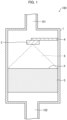
- Fig. 1 is a view schematically illustrating a configuration of a hydrolyzing device 100, including a container 1, in accordance with Embodiment 1 of the present invention.
- Fig. 2 is a view schematically illustrating a nozzle 2 of the container 1.
- Fig. 3 is a cross-sectional view of a section taken along line A-A' of the nozzle 2 illustrated in Fig. 2 .
- Fig. 4 is a cross-sectional view illustrating an internal structure of a spraying part 13 of the nozzle 2.
- Fig. 5 is a view illustrating how a liquid 6 adheres to a spray target surface P on which the liquid 6 has been sprayed by using the nozzle 2.
- the hydrolyzing device 100 in accordance with Embodiment 1 is a device for cleaning emissions by supplying a denitration catalyst with a gas containing ammonia (NH 3 ) and decomposing nitrogen oxides contained in the emissions into nitrogen and water through a selective catalytic reduction (SCR) reaction using, as a reducing agent, the ammonia.
- the hydrolyzing device 100 includes the container 1, a bleed air line 101, a treatment gas line 102, and a heater (not illustrated).
- the heater heats a bleed air of exhaust from an engine such as a diesel engine.
- the bleed air having been heated is supplied to the container 1 through the bleed air line 101.
- the container 1 is a device for hydrolyzing the liquid 6 inside the container 1 to generate ammonia.
- the liquid 6 is an aqueous urea solution.
- the container 1 stores a spray target object 5, which is a catalyst for accelerating a hydrolysis reaction.
- the container 1 includes the nozzle 2 for spraying the spray target object 5 with the liquid 6.
- the container 1 further includes a pipe 4 for supporting the nozzle 2 and supplying the nozzle 2 with the liquid 6. The nozzle 2 is supplied with the liquid 6 through the pipe 4.
- the nozzle 2 sprays the spray target object 5 with the liquid 6.
- the liquid 6 having been sprayed is hydrolyzed by a hot gas (bleed air) introduced into the container 1 to form ammonia.
- the container 1 has a shape that include, as a specific example, the shape of an axially long tube, such as the shape of a rectangular tube that is substantially square in a cross section perpendicular to an extending direction thereof.
- the container 1 is not limited to the shape of a rectangular tube, but may be cylindrical.
- the container 1 supplies, through the treatment gas line 102, a hot treatment gas into which ammonia has been mixed.
- the nozzle 2 which is provided in the container 1, is a liquid spray nozzle for spraying (misting) the liquid 6 in the form of mist, over a spray target surface P of the spray target object 5.
- the nozzle 2 includes: a nozzle body 11 connected to the pipe 4; and at least three spraying parts 13 for spraying the liquid 6.
- Described as an example in Embodiment 1 is a case where the nozzle body 11 includes, as a spraying part 13, three spraying parts: a spraying part 13A; a spraying part 13B; and a spraying part 13C.
- Fig. 4 is a cross-sectional view illustrating the structure of the spraying part 13A of the nozzle 2.
- the spraying part 13A includes: a liquid spray hole 14; a gas supply portion 15; and gas ejecting parts 17 (route control part) paired together.
- the liquid spray hole 14 is a circular opening provided in the spraying part 13.
- the liquid spray hole 14 is connected to a liquid passage 141 inside the pipe 4, and sprays the liquid 6 carried by the liquid passage 141.
- the gas supply portion 15 includes: gas spray holes 151 serving as spray holes; and gas passages 152.
- the gas spray holes 151 are a pair of openings located near the liquid spray hole 14.
- the gas passages 152 are connected to a gas passage inside the pipe 4.
- the gas passages 152 supply a gas 50 carried by the gas passage to the gas spray holes 151, which spray the gas 50 toward the liquid 6 sprayed from the spraying part 13. This makes the particle diameter of the liquid 6 sprayed from the liquid spray hole 14 smaller, so that the liquid 6 becomes misty.
- the gas ejecting parts 17 are a mechanism for controlling a region (hereinafter, referred to also as adhesion region) formed through adhesion, to the spray target surface P, of the liquid 6 sprayed from the spraying part 13.
- adhesion region a region formed through adhesion, to the spray target surface P, of the liquid 6 sprayed from the spraying part 13.
- the spray target surface P is a flat surface substantially perpendicular to a direction in which the nozzle body 11 is viewed in a plan view.
- the gas ejecting parts 17 control a route of a liquid sprayed from the liquid spray hole 14 by blowing a gas toward the liquid sprayed from the liquid spray hole 14.
- the gas ejecting parts 17 include: gas spray holes 171; and gas passages 172. Each of the gas ejecting parts 17 paired together includes corresponding one of the gas spray holes 171.
- the gas spray holes 171 are a pair of openings provided near the end of the spraying part 13A, on a straight line L (a straight line denoted by a sign L in Fig. 2 ) connecting a center point 20 (see Fig. 2 ) of the nozzle body 11 and the spraying part 13A. As illustrated in Fig. 2 , the gas spray holes 171 paired together are disposed such that the liquid spray hole 14 is placed therebetween on the straight line L. In other words, the gas spray holes 171 paired together are provided in an outer circumferential part of the spraying part 13A and also on a straight line L passing through the center of the nozzle body 11 and the liquid spray hole 14.
- the gas passages 172 are connected to another gas passage that is different from the gas passage connected to the gas passages 152 and that is provided inside the pipe 4.
- the gas passages 172 supply the gas spray holes 171 with a gas 60 carried by the other gas passage.
- the gas passages 172 and the gas passages 152 can be connected to the same gas passage provided inside the pipe 4. In such a case, the gas spray holes 171 and the gas spray holes 151 are supplied with the gas 50 carried by the same gas passage.
- the gas spray holes 171 spray, with the gas 60 supplied by the gas passages 172, the liquid 6 that have been sprayed and have become misty.
- the gas 50 and the gas 60 sprayed from the gas spray holes 151 and the gas passage 17, respectively are not limited to any particular types.
- the gas 50 and the gas 60 may be, for example, air.
- the three spraying parts 13 are disposed so as not to be located in line with each other when seen from a third direction (a direction represented by an arrow 30 in Fig. 3 ) that is perpendicular to the spray target surface P. Specifically, the three spraying parts 13 are disposed on the circumference of the same circle having a center which is the center point 20 (a position represented by a dot 20 in Fig. 2 ), which is the center of the nozzle body 11, when seen from the third direction (in other words, in the plan view, from a position where the three spraying parts 13 are disposed, of the nozzle body 11).
- the three spraying parts 13 are disposed so as to be spaced at regular intervals. In other words, the three spraying parts 13 are disposed so as to form a regular triangle when seen from the third direction. Further, the three spraying parts 13 are disposed so as to be inclined with respect to a plane perpendicular to the third direction, so that, when seen from the third direction, the liquid is sprayed in directions from the center point 20 of the nozzle body 11 to the spraying parts 13 (for example, the direction represented by an arrow 40 in a case of the spraying part 13B in Fig. 3 ).
- the liquid 6 sprayed from the liquid spray hole 14 is deformed to be flattened (oval) as a whole, so as to be shorter in a direction in which the gas spray holes 171 face each other and longer in a direction perpendicular to the direction in which the gas spray holes 171 face each other.
- the gas ejecting parts 17 control a route of the liquid such that an adhesion region S is shorter in a first direction outward from a central part of a group of the plurality of adhesion regions S than in a second direction perpendicular to the first direction.
- the configuration described above makes flattened (oval) the adhesion region S (a region denoted by a sign S in Fig. 5 ) of the liquid 6 that is sprayed from each of the spraying parts 13 and then adheres to the spray target surface P, as illustrated in Fig. 5 .
- the adhesion region S is shorter in a first direction (a direction represented by an arrow 70 in Fig. 5 ) outward from the center (center point 20) of the nozzle body 11 than in a second direction (a direction represented by an arrow 80 in Fig. 5 ) perpendicular to the first direction.
- a region T (referred to as an adhesion region T) is a group of the adhesion regions S, in which the liquid having been sprayed from the three spraying parts 13 adheres to the spray target surface P.
- an end part of one adhesion region S (a region denoted by S in Fig. 5 ) produced by one of the spraying parts 13 overlaps an end part of another adhesion region S produced by another one of the spraying parts 13.
- the gas ejecting parts 17 control the route of the liquid such that the adhesion region S is shorter in the first direction outward from the central part of the adhesion region T than in the second direction perpendicular to the first direction.
- the spray region S generated by a single spraying part 13 is flattened, an adhesion amount of the liquid 6 is likely to be reduced, in particular, in end parts thereof in a longitudinal direction.
- the three spraying parts 13 generate the spray regions S each having end parts that overlap end parts of the other spray regions S. This reduces variation in the adhesion amount of the liquid 6 within the spray region T.
- Each of the spraying parts 13 is inclined outward from the nozzle body 11.
- the spraying parts 13 therefore spray the liquid 6 in a direction outward from the nozzle body 11. This reduces the variation in the adhesion amount of the liquid 6 within the adhesion region S more than in a case where the spraying parts 13 point in the third direction.
- the liquid 6 sprayed from the spraying parts 13 is mostly sprayed substantially in the third direction.
- the liquid 6 mostly passes through the inside of the honeycomb structure of a catalyst, which is the spray target object 5, without touching the inner wall surface of the honeycomb structure. This could reduce the efficiency of a catalyzed reaction.
- each of the spraying parts 13 is inclined outward from the nozzle body 11. This causes the liquid 6 sprayed from the spraying parts 13 to be sprayed in a direction inclined with respect to the third direction. Accordingly, the liquid 6 mostly touches the inner wall surface of the honeycomb structure of the spray target object 5. This improves the efficiency of the catalyzed reaction.
- the flattened shape is adjusted by means of wind pressure of a gas jetted from the gas spray holes 171. This enables adaptation by changing the wind pressure without changing the structure of the spraying parts 13, even in a case where a condition such as the size of the spray target surface P is changed.
- the route control part described in Embodiment 1 has the configuration that involves the gas ejecting parts 17.
- a method for controlling the shape of the adhesion region S is not limited to this.
- the route control part may be a liquid spray hole 14 that is deformed to be flattened so that the adhesion region S is adjusted to be flattened.
- Fig. 6 is a view schematically illustrating a nozzle 2A in accordance with Embodiment 2 of the present invention.
- Fig. 7 is a cross-sectional view of a section taken along line B-B' of the nozzle 2A illustrated in Fig. 6 .
- Fig. 8 is a view illustrating a spray target surface P on which a liquid 6 has been sprayed by using the nozzle 2A.
- the nozzle 2A in accordance with Embodiment 2 of the present invention includes, as a spraying part 13, four spraying parts: spraying parts 13A, 13B, 13C, and 13D.
- the four spraying part 13A to 13D are disposed so as not to be located in line with each other when viewed from a third direction perpendicular to the spray target surface P.
- the four spraying parts 13 are disposed on the circumference of the same circle having a center which is a center point 20 of a nozzle body 11 when seen from the third direction.
- the four spraying parts 13 are disposed so as to be spaced at regular intervals. In other words, the four spraying parts 13 are disposed so as to form a regular triangle when seen from the third direction. Further, the four spraying parts 13 are disposed so as to be inclined with respect to a plane perpendicular to the third direction, so that, when seen from the third direction, the liquid is sprayed in directions from the center point 20 of the nozzle body 11 to the spraying parts 13.
- the nozzle 2A uses the nozzle 2A generates an adhesion region U of the liquid 6 (a region denoted by a sign U in Fig. 8 ) that is formed by four adhesion regions S. Accordingly, the adhesion region U is larger than the adhesion region T generated by using the nozzle 2. This is because the nozzle 2A includes the four spraying parts 13A to 13D. With the above configuration, the nozzle 2A enables both a reduction in the variation in an adhesion amount of the liquid 6 within the adhesion region T, as with the case of the nozzle 2, and spray of the liquid 6 in the spray region P over a larger range.
Landscapes
- Engineering & Computer Science (AREA)
- Chemical & Material Sciences (AREA)
- Combustion & Propulsion (AREA)
- Mechanical Engineering (AREA)
- General Engineering & Computer Science (AREA)
- Chemical Kinetics & Catalysis (AREA)
- Health & Medical Sciences (AREA)
- Toxicology (AREA)
- Nozzles (AREA)
- Exhaust Gas After Treatment (AREA)
- Details Or Accessories Of Spraying Plant Or Apparatus (AREA)
Applications Claiming Priority (2)
| Application Number | Priority Date | Filing Date | Title |
|---|---|---|---|
| JP2019208835A JP7181178B2 (ja) | 2019-11-19 | 2019-11-19 | ノズルおよび加水分解装置 |
| PCT/JP2020/025744 WO2021100236A1 (ja) | 2019-11-19 | 2020-07-01 | ノズルおよび加水分解装置 |
Publications (3)
| Publication Number | Publication Date |
|---|---|
| EP4063018A1 EP4063018A1 (en) | 2022-09-28 |
| EP4063018A4 EP4063018A4 (en) | 2023-11-15 |
| EP4063018B1 true EP4063018B1 (en) | 2024-09-04 |
Family
ID=75966106
Family Applications (1)
| Application Number | Title | Priority Date | Filing Date |
|---|---|---|---|
| EP20890230.4A Active EP4063018B1 (en) | 2019-11-19 | 2020-07-01 | Nozzle and hydrolyzing device |
Country Status (6)
| Country | Link |
|---|---|
| EP (1) | EP4063018B1 (da) |
| JP (1) | JP7181178B2 (da) |
| KR (1) | KR102894198B1 (da) |
| CN (1) | CN114746185B (da) |
| DK (1) | DK4063018T3 (da) |
| WO (1) | WO2021100236A1 (da) |
Families Citing this family (1)
| Publication number | Priority date | Publication date | Assignee | Title |
|---|---|---|---|---|
| KR102858224B1 (ko) * | 2022-09-21 | 2025-09-11 | 한국화학연구원 | 퍼퓨릴 알코올의 올리고머화 방지를 위한 수소화 반응기 및 수소화 방법 |
Family Cites Families (19)
| Publication number | Priority date | Publication date | Assignee | Title |
|---|---|---|---|---|
| JP3307771B2 (ja) * | 1993-08-23 | 2002-07-24 | ハンス‐ユルゲン、ガイドール | 熱間圧延鋼板のデスケーリング手段 |
| JP2002066393A (ja) | 2000-08-25 | 2002-03-05 | Freunt Ind Co Ltd | 多頭型スプレーガン及びそれを用いたコーティング装置、並びにコーティング方法 |
| JP2003093926A (ja) | 2001-09-21 | 2003-04-02 | Kyoritsu Gokin Co Ltd | 流体噴射ノズル |
| JP2004033840A (ja) | 2002-07-01 | 2004-02-05 | Yoshiyuki Nagae | 噴霧装置 |
| JP2004195335A (ja) | 2002-12-17 | 2004-07-15 | Kyowa Kogyo Kk | 拡散噴射ノズル |
| DE102004029679A1 (de) * | 2004-06-18 | 2005-12-29 | Purem Abgassysteme Gmbh & Co. Kg | Injektordüse sowie Verfahren und Verwendung einer Innjektordüse zur Einbringung von Harnstoff in ein Abgas einer Brennkraftmaschine |
| BRPI0807909B1 (pt) * | 2007-02-13 | 2020-11-24 | Bete Fog Nozzle, Inc. | bocais de pulverização |
| JP2010090836A (ja) * | 2008-10-09 | 2010-04-22 | Denso Corp | 尿素水供給装置 |
| DE102009005528A1 (de) * | 2009-01-20 | 2010-07-22 | Albonair Gmbh | Zweistoffdüse |
| DE102009034072A1 (de) * | 2009-07-22 | 2011-01-27 | Emitec Gesellschaft Für Emissionstechnologie Mbh | Einspritzdüse zur Zufuhr von Reduktionsmittel und Vorrichtung zur Behandlung von Abgasen |
| JP2011117386A (ja) | 2009-12-04 | 2011-06-16 | Volvo Powertrain Ab | エンジンの排気浄化装置 |
| JP2013002336A (ja) * | 2011-06-15 | 2013-01-07 | Toyota Industries Corp | 還元剤噴射ノズル及び還元剤噴射ノズルを備えた窒素酸化物浄化システム |
| EP2799149A4 (en) * | 2011-12-19 | 2015-03-25 | Nozzle Network Co Ltd | liquid spraying |
| CN104069968B (zh) * | 2013-03-28 | 2017-01-04 | 株式会社Enjet | 喷雾嘴和使用该喷雾嘴的涂敷系统 |
| ES2655547T3 (es) * | 2013-07-18 | 2018-02-20 | Fpt Motorenforschung Ag | Sistema para prevenir la formación de cristales de urea en un sistema de postratamiento de gas de escape |
| US10473013B2 (en) * | 2014-09-26 | 2019-11-12 | Cummins Emission Solutions, Inc. | Integrative reductant system and method using constant volume injection |
| CN204220334U (zh) * | 2014-10-13 | 2015-03-25 | 北京洛卡环保技术有限公司 | 一种烟气脱硝直喷尿素溶液喷射器 |
| US10279360B2 (en) * | 2015-07-20 | 2019-05-07 | Spraying Systems Co. | Steam atomizing liquid spray nozzle assembly |
| JP2019027347A (ja) | 2017-07-28 | 2019-02-21 | いすゞ自動車株式会社 | 後処理装置 |
-
2019
- 2019-11-19 JP JP2019208835A patent/JP7181178B2/ja active Active
-
2020
- 2020-07-01 EP EP20890230.4A patent/EP4063018B1/en active Active
- 2020-07-01 DK DK20890230.4T patent/DK4063018T3/da active
- 2020-07-01 KR KR1020227019336A patent/KR102894198B1/ko active Active
- 2020-07-01 WO PCT/JP2020/025744 patent/WO2021100236A1/ja not_active Ceased
- 2020-07-01 CN CN202080080181.7A patent/CN114746185B/zh active Active
Also Published As
| Publication number | Publication date |
|---|---|
| KR20220100908A (ko) | 2022-07-18 |
| JP2021079333A (ja) | 2021-05-27 |
| DK4063018T3 (da) | 2024-09-16 |
| CN114746185B (zh) | 2023-06-16 |
| JP7181178B2 (ja) | 2022-11-30 |
| EP4063018A1 (en) | 2022-09-28 |
| WO2021100236A1 (ja) | 2021-05-27 |
| CN114746185A (zh) | 2022-07-12 |
| KR102894198B1 (ko) | 2025-12-01 |
| EP4063018A4 (en) | 2023-11-15 |
Similar Documents
| Publication | Publication Date | Title |
|---|---|---|
| US8726643B2 (en) | Injector mounting configuration for an exhaust treatment system | |
| US8528884B2 (en) | Injection nozzle for supplying reducing agent and device for treating exhaust gases | |
| US20120020854A1 (en) | Method, system and apparatus for liquid injection into a gas system | |
| EP2339139B1 (en) | Method for dosing an urea based reducing agent into a gas exhaust stream | |
| JP4605205B2 (ja) | 排気浄化装置 | |
| CN102022165B (zh) | 一种车用尿素scr系统的混合装置 | |
| EP2312135B1 (en) | Liquid reducing agent injection nozzle | |
| JP5937517B2 (ja) | 尿素ベースの還元剤を排気ガス流へ投与する投与モジュール | |
| JP6108427B2 (ja) | 尿素水噴射ノズル | |
| JP2003510175A (ja) | 流動ガスに反応剤を供給するための装置 | |
| CN102094699A (zh) | 一种用于柴油机尿素选择性催化还原装置的静态混合器 | |
| EP4063018B1 (en) | Nozzle and hydrolyzing device | |
| EP2342432B1 (en) | Urea injector nozzle | |
| CN202028346U (zh) | 一种用于柴油机尿素选择性催化还原装置的静态混合器 | |
| CN205101083U (zh) | 一种应用于船用柴油机scr系统自激振荡脉冲雾化喷嘴 | |
| US10273849B2 (en) | Injection module and exhaust system having an injection module | |
| CN102242661A (zh) | 一种车用选择性催化还原装置scr的静态混合器 | |
| CN113302384A (zh) | 还原剂喷嘴 | |
| US20180142596A1 (en) | Injection module and exhaust system having an injection module | |
| CN220621994U (zh) | 混合器及后处理系统 | |
| CN102042063A (zh) | 一种用于柴油机尾气氮氧化物净化还原剂的雾化喷射装置 | |
| CN219242023U (zh) | 一种尿素喷嘴及scr尿素喷射系统 | |
| CN220621996U (zh) | 混合器及后处理系统 | |
| KR101587701B1 (ko) | 스태틱 믹서 | |
| EP3385516A1 (en) | Scr system and methodè |
Legal Events
| Date | Code | Title | Description |
|---|---|---|---|
| STAA | Information on the status of an ep patent application or granted ep patent |
Free format text: STATUS: THE INTERNATIONAL PUBLICATION HAS BEEN MADE |
|
| PUAI | Public reference made under article 153(3) epc to a published international application that has entered the european phase |
Free format text: ORIGINAL CODE: 0009012 |
|
| STAA | Information on the status of an ep patent application or granted ep patent |
Free format text: STATUS: REQUEST FOR EXAMINATION WAS MADE |
|
| 17P | Request for examination filed |
Effective date: 20220517 |
|
| AK | Designated contracting states |
Kind code of ref document: A1 Designated state(s): AL AT BE BG CH CY CZ DE DK EE ES FI FR GB GR HR HU IE IS IT LI LT LU LV MC MK MT NL NO PL PT RO RS SE SI SK SM TR |
|
| DAV | Request for validation of the european patent (deleted) | ||
| DAX | Request for extension of the european patent (deleted) | ||
| REG | Reference to a national code |
Ref country code: DE Ref legal event code: R079 Free format text: PREVIOUS MAIN CLASS: B05B0007080000 Ipc: B05B0007060000 Ref country code: DE Ref legal event code: R079 Ref document number: 602020037323 Country of ref document: DE Free format text: PREVIOUS MAIN CLASS: B05B0007080000 Ipc: B05B0007060000 |
|
| A4 | Supplementary search report drawn up and despatched |
Effective date: 20231018 |
|
| RIC1 | Information provided on ipc code assigned before grant |
Ipc: B05B 7/00 20060101ALI20231012BHEP Ipc: F01N 3/10 20060101ALI20231012BHEP Ipc: F01N 3/20 20060101ALI20231012BHEP Ipc: F01N 3/08 20060101ALI20231012BHEP Ipc: B05B 7/08 20060101ALI20231012BHEP Ipc: B05B 7/06 20060101AFI20231012BHEP |
|
| GRAP | Despatch of communication of intention to grant a patent |
Free format text: ORIGINAL CODE: EPIDOSNIGR1 |
|
| STAA | Information on the status of an ep patent application or granted ep patent |
Free format text: STATUS: GRANT OF PATENT IS INTENDED |
|
| INTG | Intention to grant announced |
Effective date: 20240617 |
|
| GRAS | Grant fee paid |
Free format text: ORIGINAL CODE: EPIDOSNIGR3 |
|
| GRAA | (expected) grant |
Free format text: ORIGINAL CODE: 0009210 |
|
| STAA | Information on the status of an ep patent application or granted ep patent |
Free format text: STATUS: THE PATENT HAS BEEN GRANTED |
|
| P01 | Opt-out of the competence of the unified patent court (upc) registered |
Free format text: CASE NUMBER: APP_39168/2024 Effective date: 20240701 |
|
| AK | Designated contracting states |
Kind code of ref document: B1 Designated state(s): AL AT BE BG CH CY CZ DE DK EE ES FI FR GB GR HR HU IE IS IT LI LT LU LV MC MK MT NL NO PL PT RO RS SE SI SK SM TR |
|
| REG | Reference to a national code |
Ref country code: GB Ref legal event code: FG4D |
|
| REG | Reference to a national code |
Ref country code: CH Ref legal event code: EP |
|
| REG | Reference to a national code |
Ref country code: DK Ref legal event code: T3 Effective date: 20240911 |
|
| REG | Reference to a national code |
Ref country code: IE Ref legal event code: FG4D |
|
| REG | Reference to a national code |
Ref country code: DE Ref legal event code: R096 Ref document number: 602020037323 Country of ref document: DE |
|
| REG | Reference to a national code |
Ref country code: LT Ref legal event code: MG9D |
|
| REG | Reference to a national code |
Ref country code: NL Ref legal event code: MP Effective date: 20240904 |
|
| PG25 | Lapsed in a contracting state [announced via postgrant information from national office to epo] |
Ref country code: NO Free format text: LAPSE BECAUSE OF FAILURE TO SUBMIT A TRANSLATION OF THE DESCRIPTION OR TO PAY THE FEE WITHIN THE PRESCRIBED TIME-LIMIT Effective date: 20241204 |
|
| PG25 | Lapsed in a contracting state [announced via postgrant information from national office to epo] |
Ref country code: PL Free format text: LAPSE BECAUSE OF FAILURE TO SUBMIT A TRANSLATION OF THE DESCRIPTION OR TO PAY THE FEE WITHIN THE PRESCRIBED TIME-LIMIT Effective date: 20240904 Ref country code: GR Free format text: LAPSE BECAUSE OF FAILURE TO SUBMIT A TRANSLATION OF THE DESCRIPTION OR TO PAY THE FEE WITHIN THE PRESCRIBED TIME-LIMIT Effective date: 20241205 Ref country code: FI Free format text: LAPSE BECAUSE OF FAILURE TO SUBMIT A TRANSLATION OF THE DESCRIPTION OR TO PAY THE FEE WITHIN THE PRESCRIBED TIME-LIMIT Effective date: 20240904 |
|
| PG25 | Lapsed in a contracting state [announced via postgrant information from national office to epo] |
Ref country code: BG Free format text: LAPSE BECAUSE OF FAILURE TO SUBMIT A TRANSLATION OF THE DESCRIPTION OR TO PAY THE FEE WITHIN THE PRESCRIBED TIME-LIMIT Effective date: 20240904 |
|
| PG25 | Lapsed in a contracting state [announced via postgrant information from national office to epo] |
Ref country code: LV Free format text: LAPSE BECAUSE OF FAILURE TO SUBMIT A TRANSLATION OF THE DESCRIPTION OR TO PAY THE FEE WITHIN THE PRESCRIBED TIME-LIMIT Effective date: 20240904 |
|
| PG25 | Lapsed in a contracting state [announced via postgrant information from national office to epo] |
Ref country code: HR Free format text: LAPSE BECAUSE OF FAILURE TO SUBMIT A TRANSLATION OF THE DESCRIPTION OR TO PAY THE FEE WITHIN THE PRESCRIBED TIME-LIMIT Effective date: 20240904 |
|
| PG25 | Lapsed in a contracting state [announced via postgrant information from national office to epo] |
Ref country code: ES Free format text: LAPSE BECAUSE OF FAILURE TO SUBMIT A TRANSLATION OF THE DESCRIPTION OR TO PAY THE FEE WITHIN THE PRESCRIBED TIME-LIMIT Effective date: 20240904 Ref country code: RS Free format text: LAPSE BECAUSE OF FAILURE TO SUBMIT A TRANSLATION OF THE DESCRIPTION OR TO PAY THE FEE WITHIN THE PRESCRIBED TIME-LIMIT Effective date: 20241204 |
|
| PG25 | Lapsed in a contracting state [announced via postgrant information from national office to epo] |
Ref country code: RS Free format text: LAPSE BECAUSE OF FAILURE TO SUBMIT A TRANSLATION OF THE DESCRIPTION OR TO PAY THE FEE WITHIN THE PRESCRIBED TIME-LIMIT Effective date: 20241204 Ref country code: PL Free format text: LAPSE BECAUSE OF FAILURE TO SUBMIT A TRANSLATION OF THE DESCRIPTION OR TO PAY THE FEE WITHIN THE PRESCRIBED TIME-LIMIT Effective date: 20240904 Ref country code: NO Free format text: LAPSE BECAUSE OF FAILURE TO SUBMIT A TRANSLATION OF THE DESCRIPTION OR TO PAY THE FEE WITHIN THE PRESCRIBED TIME-LIMIT Effective date: 20241204 Ref country code: LV Free format text: LAPSE BECAUSE OF FAILURE TO SUBMIT A TRANSLATION OF THE DESCRIPTION OR TO PAY THE FEE WITHIN THE PRESCRIBED TIME-LIMIT Effective date: 20240904 Ref country code: HR Free format text: LAPSE BECAUSE OF FAILURE TO SUBMIT A TRANSLATION OF THE DESCRIPTION OR TO PAY THE FEE WITHIN THE PRESCRIBED TIME-LIMIT Effective date: 20240904 Ref country code: GR Free format text: LAPSE BECAUSE OF FAILURE TO SUBMIT A TRANSLATION OF THE DESCRIPTION OR TO PAY THE FEE WITHIN THE PRESCRIBED TIME-LIMIT Effective date: 20241205 Ref country code: FI Free format text: LAPSE BECAUSE OF FAILURE TO SUBMIT A TRANSLATION OF THE DESCRIPTION OR TO PAY THE FEE WITHIN THE PRESCRIBED TIME-LIMIT Effective date: 20240904 Ref country code: ES Free format text: LAPSE BECAUSE OF FAILURE TO SUBMIT A TRANSLATION OF THE DESCRIPTION OR TO PAY THE FEE WITHIN THE PRESCRIBED TIME-LIMIT Effective date: 20240904 Ref country code: BG Free format text: LAPSE BECAUSE OF FAILURE TO SUBMIT A TRANSLATION OF THE DESCRIPTION OR TO PAY THE FEE WITHIN THE PRESCRIBED TIME-LIMIT Effective date: 20240904 |
|
| REG | Reference to a national code |
Ref country code: AT Ref legal event code: MK05 Ref document number: 1719805 Country of ref document: AT Kind code of ref document: T Effective date: 20240904 |
|
| PG25 | Lapsed in a contracting state [announced via postgrant information from national office to epo] |
Ref country code: NL Free format text: LAPSE BECAUSE OF FAILURE TO SUBMIT A TRANSLATION OF THE DESCRIPTION OR TO PAY THE FEE WITHIN THE PRESCRIBED TIME-LIMIT Effective date: 20240904 |
|
| PG25 | Lapsed in a contracting state [announced via postgrant information from national office to epo] |
Ref country code: PT Free format text: LAPSE BECAUSE OF FAILURE TO SUBMIT A TRANSLATION OF THE DESCRIPTION OR TO PAY THE FEE WITHIN THE PRESCRIBED TIME-LIMIT Effective date: 20250106 Ref country code: IS Free format text: LAPSE BECAUSE OF FAILURE TO SUBMIT A TRANSLATION OF THE DESCRIPTION OR TO PAY THE FEE WITHIN THE PRESCRIBED TIME-LIMIT Effective date: 20250104 |
|
| PG25 | Lapsed in a contracting state [announced via postgrant information from national office to epo] |
Ref country code: RO Free format text: LAPSE BECAUSE OF FAILURE TO SUBMIT A TRANSLATION OF THE DESCRIPTION OR TO PAY THE FEE WITHIN THE PRESCRIBED TIME-LIMIT Effective date: 20240904 Ref country code: SM Free format text: LAPSE BECAUSE OF FAILURE TO SUBMIT A TRANSLATION OF THE DESCRIPTION OR TO PAY THE FEE WITHIN THE PRESCRIBED TIME-LIMIT Effective date: 20240904 |
|
| PG25 | Lapsed in a contracting state [announced via postgrant information from national office to epo] |
Ref country code: EE Free format text: LAPSE BECAUSE OF FAILURE TO SUBMIT A TRANSLATION OF THE DESCRIPTION OR TO PAY THE FEE WITHIN THE PRESCRIBED TIME-LIMIT Effective date: 20240904 Ref country code: AT Free format text: LAPSE BECAUSE OF FAILURE TO SUBMIT A TRANSLATION OF THE DESCRIPTION OR TO PAY THE FEE WITHIN THE PRESCRIBED TIME-LIMIT Effective date: 20240904 |
|
| PG25 | Lapsed in a contracting state [announced via postgrant information from national office to epo] |
Ref country code: CZ Free format text: LAPSE BECAUSE OF FAILURE TO SUBMIT A TRANSLATION OF THE DESCRIPTION OR TO PAY THE FEE WITHIN THE PRESCRIBED TIME-LIMIT Effective date: 20240904 |
|
| PG25 | Lapsed in a contracting state [announced via postgrant information from national office to epo] |
Ref country code: SK Free format text: LAPSE BECAUSE OF FAILURE TO SUBMIT A TRANSLATION OF THE DESCRIPTION OR TO PAY THE FEE WITHIN THE PRESCRIBED TIME-LIMIT Effective date: 20240904 Ref country code: IT Free format text: LAPSE BECAUSE OF FAILURE TO SUBMIT A TRANSLATION OF THE DESCRIPTION OR TO PAY THE FEE WITHIN THE PRESCRIBED TIME-LIMIT Effective date: 20240904 |
|
| REG | Reference to a national code |
Ref country code: DE Ref legal event code: R097 Ref document number: 602020037323 Country of ref document: DE |
|
| PLBE | No opposition filed within time limit |
Free format text: ORIGINAL CODE: 0009261 |
|
| STAA | Information on the status of an ep patent application or granted ep patent |
Free format text: STATUS: NO OPPOSITION FILED WITHIN TIME LIMIT |
|
| 26N | No opposition filed |
Effective date: 20250605 |
|
| PG25 | Lapsed in a contracting state [announced via postgrant information from national office to epo] |
Ref country code: SE Free format text: LAPSE BECAUSE OF FAILURE TO SUBMIT A TRANSLATION OF THE DESCRIPTION OR TO PAY THE FEE WITHIN THE PRESCRIBED TIME-LIMIT Effective date: 20240904 |
|
| PGFP | Annual fee paid to national office [announced via postgrant information from national office to epo] |
Ref country code: DE Payment date: 20250528 Year of fee payment: 6 Ref country code: DK Payment date: 20250714 Year of fee payment: 6 |
|
| PGFP | Annual fee paid to national office [announced via postgrant information from national office to epo] |
Ref country code: CH Payment date: 20250801 Year of fee payment: 6 |
|
| PG25 | Lapsed in a contracting state [announced via postgrant information from national office to epo] |
Ref country code: LU Free format text: LAPSE BECAUSE OF NON-PAYMENT OF DUE FEES Effective date: 20250701 |
|
| GBPC | Gb: european patent ceased through non-payment of renewal fee |
Effective date: 20250701 |
|
| REG | Reference to a national code |
Ref country code: BE Ref legal event code: MM Effective date: 20250731 |
|
| PG25 | Lapsed in a contracting state [announced via postgrant information from national office to epo] |
Ref country code: GB Free format text: LAPSE BECAUSE OF NON-PAYMENT OF DUE FEES Effective date: 20250701 |
|
| PG25 | Lapsed in a contracting state [announced via postgrant information from national office to epo] |
Ref country code: BE Free format text: LAPSE BECAUSE OF NON-PAYMENT OF DUE FEES Effective date: 20250731 |
|
| PG25 | Lapsed in a contracting state [announced via postgrant information from national office to epo] |
Ref country code: FR Free format text: LAPSE BECAUSE OF NON-PAYMENT OF DUE FEES Effective date: 20250731 |