EP4060815B1 - Kontaktsystem und baugruppe - Google Patents
Kontaktsystem und baugruppe Download PDFInfo
- Publication number
- EP4060815B1 EP4060815B1 EP22162218.6A EP22162218A EP4060815B1 EP 4060815 B1 EP4060815 B1 EP 4060815B1 EP 22162218 A EP22162218 A EP 22162218A EP 4060815 B1 EP4060815 B1 EP 4060815B1
- Authority
- EP
- European Patent Office
- Prior art keywords
- contact
- housing
- contact body
- conductor
- equipotential bonding
- Prior art date
- Legal status (The legal status is an assumption and is not a legal conclusion. Google has not performed a legal analysis and makes no representation as to the accuracy of the status listed.)
- Active
Links
Images



Classifications
-
- H—ELECTRICITY
- H01—ELECTRIC ELEMENTS
- H01R—ELECTRICALLY-CONDUCTIVE CONNECTIONS; STRUCTURAL ASSOCIATIONS OF A PLURALITY OF MUTUALLY-INSULATED ELECTRICAL CONNECTING ELEMENTS; COUPLING DEVICES; CURRENT COLLECTORS
- H01R4/00—Electrically-conductive connections between two or more conductive members in direct contact, i.e. touching one another; Means for effecting or maintaining such contact; Electrically-conductive connections having two or more spaced connecting locations for conductors and using contact members penetrating insulation
- H01R4/28—Clamped connections, spring connections
- H01R4/38—Clamped connections, spring connections utilising a clamping member acted on by screw or nut
- H01R4/46—Clamping area between two screws placed side by side
-
- H—ELECTRICITY
- H01—ELECTRIC ELEMENTS
- H01R—ELECTRICALLY-CONDUCTIVE CONNECTIONS; STRUCTURAL ASSOCIATIONS OF A PLURALITY OF MUTUALLY-INSULATED ELECTRICAL CONNECTING ELEMENTS; COUPLING DEVICES; CURRENT COLLECTORS
- H01R11/00—Individual connecting elements providing two or more spaced connecting locations for conductive members which are, or may be, thereby interconnected, e.g. end pieces for wires or cables supported by the wire or cable and having means for facilitating electrical connection to some other wire, terminal, or conductive member, blocks of binding posts
- H01R11/11—End pieces or tapping pieces for wires, supported by the wire and for facilitating electrical connection to some other wire, terminal or conductive member
-
- H—ELECTRICITY
- H01—ELECTRIC ELEMENTS
- H01R—ELECTRICALLY-CONDUCTIVE CONNECTIONS; STRUCTURAL ASSOCIATIONS OF A PLURALITY OF MUTUALLY-INSULATED ELECTRICAL CONNECTING ELEMENTS; COUPLING DEVICES; CURRENT COLLECTORS
- H01R4/00—Electrically-conductive connections between two or more conductive members in direct contact, i.e. touching one another; Means for effecting or maintaining such contact; Electrically-conductive connections having two or more spaced connecting locations for conductors and using contact members penetrating insulation
- H01R4/28—Clamped connections, spring connections
- H01R4/30—Clamped connections, spring connections utilising a screw or nut clamping member
- H01R4/304—Clamped connections, spring connections utilising a screw or nut clamping member having means for improving contact
-
- H—ELECTRICITY
- H01—ELECTRIC ELEMENTS
- H01R—ELECTRICALLY-CONDUCTIVE CONNECTIONS; STRUCTURAL ASSOCIATIONS OF A PLURALITY OF MUTUALLY-INSULATED ELECTRICAL CONNECTING ELEMENTS; COUPLING DEVICES; CURRENT COLLECTORS
- H01R4/00—Electrically-conductive connections between two or more conductive members in direct contact, i.e. touching one another; Means for effecting or maintaining such contact; Electrically-conductive connections having two or more spaced connecting locations for conductors and using contact members penetrating insulation
- H01R4/28—Clamped connections, spring connections
- H01R4/30—Clamped connections, spring connections utilising a screw or nut clamping member
- H01R4/36—Conductive members located under tip of screw
-
- H—ELECTRICITY
- H01—ELECTRIC ELEMENTS
- H01R—ELECTRICALLY-CONDUCTIVE CONNECTIONS; STRUCTURAL ASSOCIATIONS OF A PLURALITY OF MUTUALLY-INSULATED ELECTRICAL CONNECTING ELEMENTS; COUPLING DEVICES; CURRENT COLLECTORS
- H01R4/00—Electrically-conductive connections between two or more conductive members in direct contact, i.e. touching one another; Means for effecting or maintaining such contact; Electrically-conductive connections having two or more spaced connecting locations for conductors and using contact members penetrating insulation
- H01R4/70—Insulation of connections
-
- H—ELECTRICITY
- H02—GENERATION; CONVERSION OR DISTRIBUTION OF ELECTRIC POWER
- H02G—INSTALLATION OF ELECTRIC CABLES OR LINES, OR OF COMBINED OPTICAL AND ELECTRIC CABLES OR LINES
- H02G13/00—Installations of lightning conductors; Fastening thereof to supporting structure
Definitions
- the invention relates to a contact system for electrically contacting a conductor with a potential equalization bar and to an assembly with such a contact system.
- Equipotential bonding bars are intended for protection and functional equipotential bonding, for example in the area of lightning protection.
- the equipotential bonding bars are part of the respective electrical installation, in particular part of the internal and external lightning protection of a building.
- contact systems In order to connect electrical conductors to an equipotential bonding bar, contact systems are usually used which fix the conductor to the equipotential bonding bar and at the same time establish the electrical contact between the conductor and the equipotential bonding bar.
- spark-free equipotential bonding bars are required. With these special equipotential bonding bars, the contact systems prevent sparks from occurring. In this respect, the contact systems provide what is known as spark-free equipotential bonding.
- a contacting system in which a threaded bolt is provided with two nuts, each of which is assigned a washer.
- the US 2018/0358730 A1 shows a fastening structure made of a rubber to connect conductors.
- a contact sealing disc which comprises an electrically conductive circular ring disc.
- the FR 3 096 840 A1 also shows a screw connection of two conductors.
- a cable termination is known, into which the strands of a cable are inserted and clamped by means of a screw.
- the object of the invention is therefore to improve the electrical contact with the equipotential bonding bar.
- a contact system for electrically contacting a conductor with a potential equalization rail, which has an electrically conductive contact body and a fastening device.
- the fastening device can be fastened to the potential equalization rail and is designed to fix the conductor to the contact body in a force-fitting manner.
- the contact body has a first contact side with a first flat contact area and a second contact side with a second flat contact area. The two contact sides are opposite to each other.
- the contact body can be contacted with the conductor via the first flat contact area and with the equipotential bonding bar via the second flat contact area.
- the contact body also has an edge area that extends from the first contact area to the second contact area and has a rounded portion.
- the fastening device has a bracket that has fastening openings through which the bracket can be fastened to the equipotential bonding bar.
- the bracket has a loading area in the middle through which the conductor can be fixed to the first contact area.
- the object of the invention is further achieved by an assembly comprising a potential equalization bar and a contact system as described above.
- the basic idea of the invention is to electrically contact the conductor and the equipotential bonding rail via an intermediate element, namely the contact body. Due to the flat contact areas, which are particularly flat, the contact body ensures good electrical contact between the conductor and the contact body and between the contact body and the equipotential bonding rail.
- the conductor is spaced apart from the equipotential bonding rail by the contact body, so that the distance from the edges of the conductor to the equipotential bonding rail is increased.
- edges in the contact area of the components are avoided by rounding the edge area, which means that the electrical contact can be made without sparks, in particular in a seal-free state, i.e. without an additional seal.
- the conductor can therefore also be attached with less effort and less assembly force, so that the attachment of the conductor to the equipotential bonding rail is simplified.
- the electrical contact between the potential rail and the contact body and between the contact body and the conductor is formed by direct contact between the corresponding surfaces on the conductor, the potential equalization rail or the contact body. In other words, a surface contact is established there.
- the assembly can be used in potentially explosive areas (Ex areas).
- the contact body can be a contact body, in particular a substantially disc-shaped one. Accordingly, the contact body has a rounding perpendicular to the central axis. In other words, the contact body can be a circular cylinder.
- the rounding can (additionally or alternatively) extend along the central axis of the contact body, so that the edge region of the contact body has the rounding along the central axis or is rounded in a direction parallel to the central axis, in particular semicircular in cross-section along the central axis.
- the contact body can be a barrel body, in particular a circular barrel body. Accordingly, the edge area is rounded in two vertical directions, for example in the horizontal direction and in the vertical direction. This gives the barrel shape of the contact body.
- the bracket fastens the conductor to the contact body and at the same time the contact body is firmly attached to the equipotential bonding bar.
- the bracket can press the conductor onto the contact body to ensure contact between the conductor and the contact body. This occurs when the bracket is attached to the fastening device, in particular to the equipotential bonding bar. At the same time, the bracket can fix the contact body via the conductor, in particular to the equipotential bonding bar, by indirectly pressing the contact body onto the equipotential bonding bar.
- the bracket is (essentially) plate-like, with the loading area being formed by a bulge, so that the loading area is in a different plane than the fastening openings.
- the bracket can be made of metal.
- the edge region forms the outer surface of the essentially cylindrical contact body.
- an outward-facing surface of the edge region can be convex. In this way, the current flows from one contact surface to the other contact surface primarily through the interior of the contact body, i.e. in particular not over the edge region that has the rounding.
- the geometry effectively prevents sparks from occurring.
- the rounding can also extend radially inwards relative to the central axis of the contact body.
- the outward-facing surface of the edge area is concave.
- the rounding or the rounded area resulting from the rounding can extend from a first point to a second point, which lie on an axis that is parallel to the central axis of the contact body.
- the outward-facing surface of the edge area can be convex or concave.
- the contact body can be designed to be rotationally symmetrical with respect to its central axis.
- the central axis of the contact body represents an axis of symmetry.
- the contact body can also be arranged on the equipotential bonding rail rotated by 180° with respect to its axis of symmetry. This simplifies assembly, as no special orientation of the contact body on the equipotential bonding rail needs to be taken into account.
- the contact body has a base and the edge region, which is ring-shaped and completely accommodates the base in the radial direction.
- the first contact region and the second contact region are provided on the base.
- the current flow through the contact body can thus be influenced by the shape of the base and the edge region.
- the contact body has two opposite sides on which the base can be contacted, whereby these two sides have the corresponding contact areas of the contact body. Accordingly, the electrical contact is made via the base of the contact body.
- the contact body is formed in two parts. Accordingly, the base and the annular edge region are formed separately from one another and are put together to form the contact body.
- the edge area can be made of a material that has a lower electrical conductivity than the base of the contact body.
- the edge area is made of stainless steel and the base is made of copper.
- the electrical conductivity of the edge region changes along the radius, in particular decreasing radially outwards, so that there is no jump in the electrical conductivity in the transition region between the base and the edge region.
- the contact body can be designed such that a groove or recess is formed between the contact areas and the edge area, thereby providing at least a superficial separation of these areas.
- the contact body can also be made up of three parts.
- the contact body has an annular region between the base and the edge region.
- the contact system is designed to electrically contact a flat conductor with the equipotential bonding rail and has an adapter for round conductors.
- the adapter has a receptacle for the round conductor, into which the round conductor can be inserted and fastened.
- the adapter has a contact area with a rectangular cross-section, which can be coupled to the contact body by means of the fastening device.
- the contact system can therefore basically be used for many different conductors, because flat conductors can be contacted directly and round conductors can be contacted accordingly using the adapter.
- the holder can be circular in cross-section so that the round conductor can be securely held.
- the receptacle can have an opening on one end face that is perpendicular to at least one fixing opening through which a fixing means for the round conductor is inserted.
- the fixing means protrudes into a receiving chamber, wherein the round conductor can be fixed in the receptacle via the fixing means.
- the fixing means thus acts on the round conductor perpendicular to the insertion direction of the round conductor.
- the fixing means ensures that the round conductor is securely received in the adapter, in particular within the receiving chamber.
- the fixing means is a screw.
- an electrically non-conductive, porous insert can be arranged in the holder, which has a through-opening adapted to the cross-section of the round conductor.
- the insert can be inserted into the holder, which narrows the cross-section. This can also ensure that the round conductor is securely held.
- the insert is a porous plastic, such as an open-pore plastic.
- the adapter has an end cap that is attached to the adapter holder in a way that can be removed without tools.
- the end cap has an insertion opening that is adapted to the cross-section of the round conductor. The end cap prevents dirt or dust from entering the holder.
- the end cap can have additional ventilation openings that improve heat transfer out of the holder.
- the end cap can be attached to the adapter with a snap-in connection, particularly in the area where the adapter is mounted, i.e. on the front side.
- locking hooks are formed on the end cap and a corresponding undercut on the holder into which the locking hooks engage.
- the contact system has a housing in which the contact body is arranged, wherein the housing is open in the area of the contact areas so that the contact areas are freely accessible.
- the contact body can be accommodated in the housing so that it is partially surrounded by the housing.
- the contact body can be positioned on the equipotential bonding rail using the housing.
- the housing is dimensioned according to the equipotential bonding rail. The housing therefore makes it easier to mount the conductor on the equipotential bonding rail. First, the contact body is positioned on the equipotential bonding rail via the housing and then the conductor is placed on the housing in the area of the contact surfaces and fixed to the housing.
- a cavity can be formed within the housing into which the contact body is received or inserted, wherein the contact body is held captively and in position in the housing via its edge region.
- the contact body is therefore arranged at a predetermined position relative to the equipotential bonding bar. This ensures good contact between the equipotential bonding bar and the contact body.
- holding means are provided on the housing which grip the contact body in the edge area and fix the contact body in the housing.
- an electrically non-conductive, porous insert is also placed in the cavity.
- the insert is made of an open-pore plastic.
- the housing can be made up of several parts and have an upper housing part and a lower housing part. This simplifies the insertion of the contact body into the housing, since the contact body is first inserted into one of the two housing parts, in particular the lower housing part. The other housing part, in particular the upper housing part, is then placed on top like a lid, so that the contact body is accommodated in the housing.
- the housing only consists of the upper and lower housing parts. Accordingly, the housing has a simple structure.
- the housing can have a spring-loaded receptacle in the region of the cavity, via which the contact body is received in the housing, in particular in a captive manner.
- a positioning device is formed on the housing, in particular on the lower housing part, by means of which the housing can be positioned on the equipotential bonding rail.
- the housing can be arranged on the equipotential bonding rail in two different orientations. The different orientations serve to electrically connect conductors with different cross-sections. In this way, the flexibility in attaching the conductor to the equipotential bonding rail is increased.
- the second orientation does not mean the orientation of the first orientation rotated by 180°, but one that is different from it.
- the two orientations are offset by 90° from each other.
- a conductor with a first cross-section in the first orientation, can be electrically contacted with the equipotential bonding bar, and in the second orientation, a conductor with a second cross-section can be connected to the equipotential bonding bar.
- the contact system thus provides a high degree of flexibility when connecting conductors.
- the first orientation is designed for a flat conductor with a width of 40 mm and the second orientation for a flat conductor with a width of 30 mm.
- the positioning device is latching hooks that extend from one side of the housing, in particular from an underside of the lower housing part that is assigned to the equipotential bonding bar.
- the lower housing part can be moved along the equipotential bonding rail when positioned on the equipotential bonding rail.
- the housing is then also fixed to the equipotential bonding rail using the fastening device. This is done by the fastening device pressing the conductor onto the contact body and optionally also partially onto the housing, whereby both are pressed towards the equipotential bonding rail.
- the contact body in turn transfers the applied force partially to the housing, in particular the lower housing part, so that the housing is fixed to the equipotential bonding rail using the fastening device.
- At least two guide elements are provided on the housing, in particular on the upper housing part, which position the flat conductor or the adapter relative to the contact body. In this way, the conductor is also positioned exactly relative to the contact body.
- the guide elements can be spaced apart from one another in such a way that flat conductors or adapters with different widths can be accommodated. In this way, a contact system with a high degree of flexibility in the attachment of conductors is provided.
- adjacent guide elements are spaced at different distances from each other.
- the different distances can be used to ensure the appropriate orientations that are intended to accommodate conductors of different widths.
- two adjacent guide elements are spaced apart from each other in such a way that a flat conductor with a first width, for example a width of 40 mm, can be inserted in a guided manner
- two other adjacent Guide elements are spaced apart from one another in such a way that a flat conductor with a first width, for example a width of 30 mm, can be inserted in a guided manner.
- the term "inserted in a guided manner" is understood to mean that the flat conductor either rests against the guide elements or has a distance of less than 5 mm from the guide elements, in particular less than 2 mm.
- Each guide element has a first contact surface and a second contact surface, which are arranged at right angles to each other.
- the guide elements are essentially L-shaped in plan view.
- the guide elements are arranged on the housing in such a way that first contact surfaces of adjacent guide elements and second contact surfaces of adjacent guide elements are opposite each other in order to form corresponding guides for the respective conductors.
- the first contact surfaces each have a first distance from each other, which is different from a second distance that the second contact surfaces each have from each other.
- Figure 1 shows an assembly 10 which has a potential equalization bar 12 and a contact system 14.
- a conductor for example a flat conductor 16 can be electrically connected to the potential equalization bar 12 via the contact system 14 and can be mechanically fixed to the potential equalization bar 12.
- the contact system 14 serves to electrically connect the flat conductor 16 to the equipotential bonding bar 12 and to mechanically fix it.
- fastening openings 18 are formed, which have a defined distance from each other.
- various components to be electrically contacted can be attached to the fastening openings 18, for example by means of the contact system 14.
- the equipotential bonding bar 12 is electrically conductive and is made, for example, of a metal such as copper or stainless steel.
- the contact system 14 has a fastening device 20, which can be fastened in the fastening openings 18 of the equipotential bonding rail 12, and an electrically conductive contact body 22.
- the fastening device 20 comprises fastening means in the form of screws 24 and a bracket 26, in particular a metallic, electrically conductive bracket 26.
- the fastening means can also be formed by bolts or the like.
- the bracket 26 is essentially plate-shaped, i.e. it has a smaller thickness than its length and width, and has a fastening opening 28 at each of two opposite ends, which is adapted to the fastening means or the screws 24.
- the fastening openings 28 of the bracket 26 have the same diameter as the fastening openings 18 of the equipotential bonding rail 12, so that the bracket 26 can be fastened to the equipotential bonding rail 12 by means of the screws 24 (see Figure 2 ).
- the screws 24 are M10 screws, whereby the fastening openings 18 of the equipotential bonding bar 12 are correspondingly designed with an M10 internal thread.
- a loading area 30 is formed centrally on the bracket 26 between the fastening openings 28.
- the application area 30 is a bulge 32 of the essentially plate-shaped bracket 26, which bulges in the attached state of the bracket 26 in the direction of the equipotential bonding bar 12 ( Figure 2 ).
- the application area 30 designed in this way can ensure a correspondingly good electrical contact and at the same time mechanical fixation of the conductor.
- the contact body 22 is designed as a barrel body, in particular as a circular barrel body, wherein the height is less than the diameter of the base area.
- the contact body 22 has a first contact side 34 on which a first planar contact region 36 is formed, for example in the form of a flat or level surface, and a second contact side 38 with a second planar contact region 40, for example in the form of a planar or level surface.
- the contact sides 34, 38 are provided opposite one another on the contact body 22.
- a rounded edge region 42 extends between the contact sides 34, 38.
- the edge region 42 has a rounding 44, which is in the design of the Figure 1 from the first contact side 34 to the second contact side 38 and also extends in the circumferential direction. This results in the shape of the circular barrel body of the contact body 22.
- the entire outward-facing surface of the edge region 42 is convex.
- the edge region 42 completely encloses both the first contact region 36 and the second contact region 40 in the radial direction.
- the contact body 22 can also be designed as a circular cylinder, with the edge region forming the outer surface of the cylindrical contact body 22.
- the edge region 42 completely encloses both the first contact region 36 and the second contact region 40 in the radial direction.
- Figure 2 shows the contact system 14 attached to the equipotential bonding bar 12.
- the contact body 22 with the second contact area 40 lies directly on the equipotential bonding bar 12 and thus establishes an electrical contact between the contact body 22 and the equipotential bonding bar 12.
- the flat conductor 16 is arranged between the bracket 26 and the contact body 22 and lies directly on the first contact side 34 of the contact body 22.
- the contact body 22 is electrically contacted with the flat conductor 16 via the first contact area 36 and an electrical contact is also established between the flat conductor 16 and the equipotential bonding bar 12 via the contact body 22.
- the fastening device 20 fixes the flat conductor 16 and the contact body 22 force-fittingly to the equipotential bonding bar 12.
- the bracket 26 is mechanically fixed to the equipotential bonding bar 12 via the screws 24 and the application area 32 lies directly on the flat conductor 16, so that the flat conductor 16 is pressed against the contact body 22 and thus the contact body 22 is pressed against the equipotential bonding bar 12.
- the contact body 22 is thus fixed in a force-fitting manner to the equipotential bonding bar 12 and the conductor 16 is fixed in a force-fitting manner to the contact body 22.
- the current flows through the contact body 22 primarily via the center of the contact body 22, i.e. directly from the first contact region 36 to the second contact region 38. This keeps the current away from the edge region 42 so that no sparks can occur at the edge region 42 of the contact body 22.
- the flat conductor 16 can be attached to the contact body 22 with a lower assembly force. In this way, the assembly effort simplified compared to the contact systems known from the state of the art.
- Figure 3 shows a second embodiment of the contact system 14.
- the contact body 22 is not formed in one piece, but in two parts.
- the contact body 22 accordingly has the edge region 42 and a base 46 which is completely received in the radial direction by the annular edge region 42.
- the contact areas 36, 40 are formed on opposite sides of the base 46 and the edge area 42 surrounds the base 46 in such a way that only the contact areas 36, 40 are accessible from the outside, as can be seen from Figure 3 emerges.
- the base 46 has better electrical conductivity than the edge region 42. This ensures that the current from the flat conductor 16 to the equipotential bonding bar 12 flows primarily or mainly via the base 46. This is ultimately due to how large the differences in electrical conductivity are.
- the edge region 42 therefore has only a low charge density, so that no sparks can occur on the contact body 22.
- the base 46 is made of copper or silver and the edge region 42 is made of stainless steel or a non-conductive plastic.
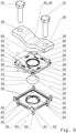
- the Figures 4 to 8 show a third embodiment of the assembly 10 or the contact system 14.
- the contact body 22 is again made in one piece, i.e. corresponding to the first embodiment.
- the contact body 22 is arranged in a housing 48 which is formed in several parts.
- the housing 48 is in two parts and consists of an upper housing part 50 and a lower housing part 52.
- a cavity 54 is formed within the housing 48 ( Figure 6 ).
- the housing parts 50, 52 are detachably connected to one another via a locking connection 53.
- Locking hooks 55 are formed on the lower housing part 52, which engage with corresponding locking sections 57 ( Figure 5 ) engage on the upper housing part 50, whereby the locking connection 54 of the two housing parts 50, 52 can be established.
- Each housing part 50, 52 has a contact opening 56 and, in the region of the contact openings 56, also has holding means 58 by means of which the contact body 22 is held within the housing 48.
- the contact body 22 is arranged within the cavity 54 and the holding means 58 engage the edge region 42 of the contact body 22.
- the contact body 22 is arranged within the housing 48 such that the contact areas 36, 40 are accessible via the contact openings 56 in the housing parts 50, 52. In this respect, electrical contact can be made even if the contact body 22 is accommodated in the housing 48.
- An electrical contact is already formed between the contact body 22 and the equipotential bonding bar 12 or the flat conductor 16 when the housing 48 is positioned on the equipotential bonding bar 12 or the flat conductor 16 is fixed to the housing 48.
- a positioning device 60 is formed on the lower housing part 52.
- the positioning device 60 is formed by latching hooks 62, each of which has two projections 64.
- the projections 64 on each latching hook 62 are offset from one another by 90°.
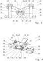
- the housing 48 with the received contact body 22 can be positioned on the potential equalization rail 12 ( Figure 4 ).
- the projections 64 engage the edge of the potential equalization rail 12, so that the housing 48 with the received contact body 22 can still be moved along the potential equalization rail 12, but cannot be removed from the potential equalization rail 12 without releasing the positioning device 60.
- the housing 48 can also be positioned in two different orientations on the equipotential bonding rail 12 by means of the positioning device 60.
- the two different orientations are offset from each other by 90°.
- the first projection 64 of a locking hook 62 interacts with the potential equalization rail 12
- the second projection 64 of the locking hook 62 interacts with the potential equalization rail 12.
- the upper housing part 50 has a plurality of guide elements 66 which protrude from an upper side of the housing 48, in particular from an upper side of the upper housing part 50.
- the flat conductor 16 is arranged in a specific position above the contact body 22 and is simultaneously guided via the guide elements 66.
- the flat conductor 16 is positioned centrally above the contact body 22.
- a first contact surface 68 and a second contact surface 69 are formed on each guide element 66, against which the flat conductor 16 rests in the attached state on the contact system 14. This ensures that the flat conductor 16 is guided.
- the opposing first contact surfaces 68 of adjacent guide elements 66 have a first distance d 1 from each other and the opposing second contact surfaces 69 of adjacent guide elements 66 have a second distance d 2 .
- the first distance d 1 is 40 mm and the second distance d 2 is 30 mm.
- the distances d 1 , d 2 are indicated by corresponding markings 70 on the top of the upper housing part 50.
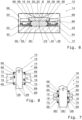
- the housing 48 can be attached to the equipotential bonding rail 12 in two orientations due to the positioning device 60 and the distance d 1 , d 2 of the contact surfaces 68, 69 is different, flat conductors 16 with different widths can be safely accommodated in the different orientations. This is shown in the Figures 7 and 8 shown.
- the housing 48 is fastened to the equipotential bonding rail 12 in the first orientation and a flat conductor 16 with a width of 40 mm is accommodated between the guide elements 66.
- the flat conductor 16 rests on the first contact surfaces 68 of the guide elements 66.
- FIG. 9 shows a further embodiment of the housing 48.
- a porous, electrically non-conductive insert 72 is additionally accommodated in the cavity 54 of the housing 48, which insert surrounds the contact body 22 in the edge region.
- the porous insert 72 is made of an open-pore plastic.
- the insert 72 can additionally prevent the spread of a spark within the cavity 54. This creates redundancy.
- the contact system 14 can also additionally attach a round conductor 74 to the equipotential bonding bar 12.
- the contact system 14 has an adapter 76, which is described in detail in the Figures 11 and 12 shown.
- the adapter 76 has a contact area 78 and a receptacle 80 via which the round conductor 74 is attached to the adapter 76.
- the adapter 76 corresponds to a flat conductor 16 and accordingly the adapter 76 in the contacting area 78 is rectangular in cross-section.
- the adapter 76 is attached to the housing 48 via the contact area 78, wherein the adapter 76 is electrically connected to the equipotential bonding bar 12 via the contact area 78 and the contact body 22.
- the receptacle 80 has a receiving chamber 82, an electrically non-conductive, porous insert 84 and an end cap 86.
- the receiving chamber 82 has an opening 88 on one end face of the adapter 76, wherein the round conductor 74 is guided into the receiving chamber 82 via the opening 88 and is fixed in the receiving chamber 82 by means of fixing means 90.
- the fixing means 90 are screws 92 which are inserted into fixing openings 94 of the adapter 76, for example grub screws.
- the fixing means 90 protrude into the receiving chamber 82 and press on the round conductor 74 perpendicular to the insertion direction of the round conductor 74. In this way, the round conductor 74 is fixed within the adapter 76. The round conductor 74 contacts the inner wall of the receiving chamber 82 so that the round conductor 74 is electrically conductively connected to the contact area 78.
- the insert 84 is arranged within the receiving chamber 82 and comprises a through opening 96 which is adapted to the cross-section of the round conductor 74.
- the diameter of the through-hole 96 therefore essentially corresponds to the diameter of the round conductor 74.
- the round conductor 74 is guided through the insert 84 via the through-opening 96 and is thus positioned with one end within the receiving chamber 82.
- the end cap 86 closes the receiving chamber 82 at the end and is detachably attached to the opening 88, for example via a corresponding snap-in connection or by being plugged on.
- the end cap 86 has an insertion opening 98 through which the round conductor 74 is guided and ventilation openings 100.
- the insertion opening 98 is adapted to the cross-section of the round conductor 74 so that the round conductor 74 can be guided through the insertion opening 98 into the receiving chamber 82 ( Figure 10 ).
- the ventilation openings 100 are arranged circumferentially around the insertion opening 98 and warmed air can escape to the outside via the ventilation openings 100.
- the ventilation openings 100 improve the heat transport out of the receiving chamber 82.
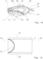
- the contact body 22 of the Figures 13 and 14 also rotationally symmetrical to the central axis M of the contact body 22, from which different radii r and r 0 are drawn, which will be discussed below.
- the contact body 22 is designed in three parts and has between the base 46 and the edge region 42 an annular intermediate part 102 which contacts the base 46 via its inner side, which faces the central axis M, and the edge region 42 with its outer side. Accordingly, the annular intermediate part 102 is completely received in the radial direction between the base 46 and the edge region 42 and is arranged in the outer half of the contact body 22. More precisely, the intermediate part 102 is arranged between 60% and 75% of the radius r of the contact body 22.
- the intermediate part 102 has a thickness d2 in the radial direction that is smaller than the thickness d1 of the edge region 42 in the radial direction.
- the thickness d2 of the intermediate part 102 is smaller than the radius r 0 of the base 46.
- the intermediate part 102 has a third electrical conductivity which is smaller than the electrical conductivity of the base 46 and greater than the electrical conductivity of the edge region 42. In this way, the current density in the edge region 42 is kept as low as possible, while at the same time jumps in the electrical conductivity are prevented.
- the rounding 44 can extend along the central axis M of the contact body 22, so that a convex ( Figures 1 to 3 ) or concave ( Figures 13 and 14 ) surface of the edge region 42 which faces outwards. Accordingly, the edge region of the contact body 22 has the rounding 44 along the central axis M or the contact body 22 is rounded in a direction parallel to the central axis M.
- the contact body 22 can also be rounded in a direction perpendicular to the central axis M, as shown in all embodiments.
Landscapes
- Connector Housings Or Holding Contact Members (AREA)
- Coupling Device And Connection With Printed Circuit (AREA)
- Elimination Of Static Electricity (AREA)
- Installation Of Bus-Bars (AREA)
Description
- Die Erfindung betrifft ein Kontaktsystem zur elektrischen Kontaktierung eines Leiters mit einer Potentialausgleichsschiene sowie eine Baugruppe mit einem solchen Kontaktsystem.
- Potentialausgleichsschienen werden für den Schutz und Funktionspotentialausgleich vorgesehen, beispielsweise im Bereich des Blitzschutzes. Dabei sind die Potentialausgleichsschienen Bestandteil der jeweiligen Elektroinstallation, insbesondere Bestandteil des inneren und äußeren Blitzschutzes eines Gebäudes.
- Um elektrische Leiter an eine Potentialausgleichsschiene anzuschließen werden üblicherweise Kontaktsysteme verwendet, die den Leiter an der Potentialausgleichsschiene fixieren und gleichzeitig den elektrischen Kontakt zwischen dem Leiter und der Potentialausgleichsschiene herstellen.
- Für spezielle Anwendungsfälle werden zündfunkenfreie Potentialausgleichsschienen benötigt. Bei diesen speziellen Potentialausgleichsschienen vermeiden die Kontaktsysteme, dass Funken entstehen. Insofern stellen die Kontaktsysteme einen sogenannten zündfunkenfreien Potentialausgleich bereit.
- Funken entstehen durch Luftspalte, die zwischen dem Leiter und der Potentialausgleichsschiene vorhanden sind. Um solche Spalte zu vermeiden, sind aus dem Stand der Technik daher Kontaktsysteme bekannt, die den jeweiligen Leiter mit einer hohen Druckkraft gegen die Potentialausgleichsschiene pressen. Auf diese Weise werden zwar Luftspalte vermieden, allerdings kann dies dazu führen, dass der Leiter sich durchbiegt.
- Insbesondere in explosionsgefährdeten Bereichen (Ex-Bereiche) bestehen besondere Anforderungen an die Kontaktsysteme hinsichtlich des zündfunkenfreien Potentialausgleichs.
- Daher ist es unter anderem bekannt, den Leiter und die Potentialausgleichsvorrichtung im Kontaktbereich abzudichten. Auf diese Weise entstehen Funken nur in einem begrenzten bzw. definierten Raum und können nicht in die Umgebung außerhalb der Abdichtung gelangen. Zudem kann durch die Abdichtung keine explosionsgefährdete Atmosphäre an die Kontaktstelle gelangen.
- Die bekannten Systeme erfordern aber einen hohen Aufwand, um die gewünschte Kontaktierung zu gewährleisten.
- Aus der
DE 21 41 550 B1 ist ein Kontaktierungssystem mit einem ringförmigen Kontaktelement zur Kontaktierung von zwei Flachleitern bekannt, bei dem eine Schrauben-Mutter-Verbindung zur Klemmung verwendet wird. - In der
DE 468 948 C ist ein Kontaktierungssystem bekannt, bei dem ein Gewindebolzen mit zwei Muttern vorgesehen ist, denen jeweils eine Unterlegscheibe zugeordnet ist. - Die
US 2018/0358730 A1 zeigt eine Befestigungsstruktur aus einem Gummi, um Leiter zu verbinden. - Aus der
DE 10 2014 209 259 A1 ist eine Kontaktdichtungsscheibe bekannt, die eine elektrisch leitfähige Kreisringscheibe umfasst. - Die
FR 3 096 840 A1 - Aus der
CN 204 992 002 U ist ein Leitungsabschluss bekannt, in den Litzen einer Leitung eingeführt und mittels einer Schraube geklemmt werden. - Die Aufgabe der Erfindung ist es daher, die elektrische Kontaktierung mit der Potentialausgleichsschiene zu verbessern.
- Die Aufgabe wird erfindungsgemäß gelöst durch ein Kontaktsystem zur elektrischen Kontaktierung eines Leiters mit einer Potentialausgleichsschiene, das einen elektrisch leitfähigen Kontaktkörper und eine Befestigungsvorrichtung hat. Die Befestigungsvorrichtung ist an der Potentialausgleichsschiene befestigbar und dazu ausgebildet, den Leiter am Kontaktkörper kraftschlüssig zu fixieren. Dabei weist der Kontaktkörper eine erste Kontaktseite mit einem ersten flächigen Kontaktbereich und eine zweite Kontaktseite mit einem zweiten flächigen Kontaktbereich auf. Die beiden Kontaktseiten sind entgegengesetzt zueinander. Der Kontaktkörper ist über den ersten flächigen Kontaktbereich mit dem Leiter und über den zweiten flächigen Kontaktbereich mit der Potentialausgleichsschiene kontaktierbar. Der Kontaktkörper hat zudem einen Randbereich, der sich vom ersten Kontaktbereich zum zweiten Kontaktbereich erstreckt, und eine Rundung aufweist. Die Befestigungsvorrichtung weist einen Bügel auf, der Befestigungsöffnungen hat, über die der Bügel an der Potentialausgleichsschiene befestigbar ist. Der Bügel hat mittig einen Beaufschlagungsbereich, über den der Leiter am ersten Kontaktbereich fixierbar ist.
- Die Aufgabe der Erfindung wird ferner gelöst durch eine Baugruppe umfassend eine Potentialausgleichsschiene und ein zuvor beschriebenes Kontaktsystem.
- Der Grundgedanke der Erfindung besteht darin, den Leiter und die Potentialausgleichsschiene über ein Zwischenelement, nämlich den Kontaktkörper, elektrisch miteinander zu kontaktieren. Durch die flächigen Kontaktbereiche, die insbesondere plan ausgebildet sind, stellt der Kontaktkörper einen guten elektrischen Kontakt zwischen dem Leiter und dem Kontaktkörper sowie zwischen dem Kontaktkörper und der Potentialausgleichsschiene sicher. Dabei ist der Leiter durch den Kontaktkörper beabstandet zur Potentialausgleichsschiene, sodass der Abstand von Kanten des Leiters zur Potentialausgleichsschiene vergrößert ist. Zudem werden Kanten im Kontaktbereich der Komponenten durch die Rundung des Randbereichs vermieden, wodurch die elektrische Kontaktierung zündfunkenfrei hergestellt werden kann, insbesondere in einem dichtungsfreien Zustand, also ohne zusätzlich eingebrachte Dichtung. Der Leiter kann daher auch mit einem geringeren Aufwand und einer geringeren Montagekraft befestigt werden, sodass die Befestigung des Leiters an der Potentialausgleichsschiene vereinfacht ist.
- Dabei wird der elektrische Kontakt zwischen der Potentialschiene und dem Kontaktkörper sowie zwischen dem Kontaktkörper und dem Leiter jeweils durch einen direkten Kontakt der entsprechenden Oberflächen an dem Leiter, der Potentialausgleichsschiene bzw. dem Kontaktkörper gebildet. Mit anderen Worten wird dort jeweils ein Flächenkontakt hergestellt.
- Aufgrund des elektrisch leitfähigen Kontaktkörpers, der die entsprechende Kontaktierung sicherstellt, kann die Baugruppe in explosionsgefährdeten Bereichen (Ex-Bereichen) eingesetzt werden.
- Durch die Rundung des Randbereichs kann es sich bei dem Kontaktköper um einen, insbesondere im Wesentlichen, scheibenförmigen Kontaktkörper handeln. Demnach weist der Kontaktkörper senkrecht zur Mittelachse eine Rundung auf. Mit anderen Worten kann es sich bei dem Kontaktkörper um einen kreisrunden Zylinder handeln.
- Die Rundung kann sich (zusätzlich oder alternativ) entlang der Mittelachse des Kontaktkörpers erstrecken, sodass der Randbereich des Kontaktkörpers entlang der Mittelachse die Rundung aufweist bzw. in einer zur Mittelachse parallelen Richtung abgerundet ist, insbesondere im Querschnitt entlang der Mittelachse halbkreisförmig.
- Es kann sich bei dem Kontaktkörper um einen Tonnenkörper handeln, insbesondere einen Kreistonnenkörper. Demnach weist der Randbereich eine Rundung in zwei senkrechten Richtungen auf, beispielsweise in horizontaler Richtung sowie in vertikaler Richtung. Hierdurch ergibt sich die Tonnenform des Kontaktkörpers.
- Mit dem Bügel wird der Leiter am Kontaktkörper und gleichzeitig der Kontaktkörper kraftschlüssig an der Potentialausgleichschiene befestigt.
- Der Bügel kann den Leiter auf den Kontaktkörper drücken, um einen Kontakt zwischen dem Leiter und dem Kontaktkörper sicherzustellen. Dies findet dann statt, wenn der Bügel der Befestigungsvorrichtung befestigt wird, insbesondere an der Potentialausgleichsschiene. Gleichzeitig kann der Bügel über den Leiter den Kontaktkörper fixieren, insbesondere an der Potentialausgleichsschiene, indem der Kontaktkörper indirekt auf die Potentialausgleichsschiene gedrückt wird.
- Beispielsweise ist der Bügel (im Wesentlichen) plattenartig, wobei der Beaufschlagungsbereich durch eine Auswölbung gebildet ist, sodass der Beaufschlagungsbereich in einer anderen Ebene als die Befestigungsöffnungen liegt. Auf diese Weise wird eine einfache und kostengünstige Befestigungsvorrichtung bereitgestellt, die sicherstellt, dass der Leiter sicher fixiert ist. Der Bügel kann aus einem Metall sein.
- Ein Aspekt der Erfindung sieht vor, dass der Randbereich die Mantelfläche des im Wesentlichen zylindrischen Kontaktkörpers bildet. Alternativ oder ergänzend kann eine nach außen weisende Fläche des Randbereichs konvex ausgebildet sein. Auf diese Weise fließt der Strom von der einen Kontaktfläche zur anderen Kontaktfläche vor allem durch das Innere des Kontaktkörpers, also insbesondere nicht über den Randbereich, der die Rundung aufweist. Durch die Geometrie wird effektiv vermieden, dass Funken entstehen.
- Alternativ kann sich die Rundung auch, bezogen auf die Mittelachse des Kontaktkörpers, radial nach innen erstrecken. In diesem Fall ist die nach außen weisende Fläche des Randbereichs konkav ausgebildet.
- Grundsätzlich kann sich die Rundung bzw. der durch die Rundung entstehende abgerundete Bereich von einem ersten Punkt zu einem zweiten Punkt erstrecken, die auf einer Achse liegen, die parallel zur Mittelachse des Kontaktkörpers ist. Die nach außen weisende Fläche des Randbereichs kann dabei konvex oder konkav sein.
- Der Kontaktkörper kann in Bezug auf seine Mittelachse rotationssymmetrisch ausgebildet sein. Insofern stellt die Mittelachse des Kontaktkörpers eine Symmetrieachse dar. Auf diese Weise ist die relative Orientierung des Kontaktkörpers an der Potentialausgleichsschiene in Bezug zu seiner Symmetrieachse unerheblich. Der Kontaktkörper kann also auch um 180° gedreht in Bezug zu seiner Symmetrieachse an der Potentialausgleichschiene angeordnet werden. Dies vereinfacht die Montage, da auf keine spezielle Orientierung des Kontaktkörpers an der Potentialausgleichsschiene geachtet werden muss.
- In einer Ausgestaltung der Erfindung weist der Kontaktkörper eine Basis und den Randbereich auf, der ringförmig ausgebildet ist und die Basis in radialer Richtung vollständig aufnimmt. Dabei sind an der Basis der erste Kontaktbereich und der zweite Kontaktbereich vorgesehen. Durch die Ausformung der Basis und des Randbereichs kann somit der Stromfluss durch den Kontaktkörper beeinflusst werden. Insbesondere weist der Kontaktkörper zwei entgegengesetzte Seiten auf, an denen die Basis kontaktierbar ist, wobei diese beiden Seiten die entsprechenden Kontaktbereiche des Kontaktkörpers aufweisen. Demnach erfolgt die elektrische Kontaktierung über die Basis des Kontaktkörpers.
- Insbesondere ist der Kontaktkörper zweiteilig ausgebildet. Demnach sind die Basis und der ringförmige Randbereich separat zueinander ausgebildet, wobei sie zusammengesetzt werden, um den Kontaktkörper auszubilden.
- Um einen Stromfluss vor allem über die Basis des Kontaktkörpers, also über das Innere des Kontaktkörpers zu führen, kann der Randbereich aus einem Material sein, das eine geringere elektrische Leitfähigkeit aufweist als die Basis des Kontaktkörpers.
- Beispielsweise ist der Randbereich aus Edelstahl und die Basis aus Kupfer.
- Im Allgemeinen ist es auch denkbar, dass sich die elektrische Leitfähigkeit des Randbereichs entlang des Radius verändert, insbesondere nach radial außen abnimmt, sodass kein Sprung der elektrischen Leitfähigkeit im Übergangsbereich zwischen der Basis und des Randbereichs vorliegt.
- Grundsätzlich kann der Kontaktkörper so ausgebildet sein, dass eine Nut oder Vertiefung zwischen den Kontaktbereichen und dem Randbereich ausgebildet ist, wodurch eine zumindest oberflächliche Trennung dieser Bereiche gegeben ist.
- Der Kontaktkörper kann auch dreiteilig ausgebildet sein. Beispielsweise weist der Kontaktkörper einen ringförmigen Bereich zwischen der Basis und dem Randbereich auf.
- In einer Ausgestaltung der Erfindung ist das Kontaktsystem ausgebildet, einen Flachleiter elektrisch mit der Potentialausgleichsschiene zu kontaktieren, und hat einen Adapter für Rundleiter. Dabei weist der Adapter eine Aufnahme für den Rundleiter auf, in die der Rundleiter einsetzbar und befestigbar ist. Der Adapter hat einen im Querschnitt rechteckigen Kontaktierungsbereich, der mittels der Befestigungsvorrichtung mit dem Kontaktkörper koppelbar ist. Somit kann das Kontaktsystem grundsätzlich für viele verschiedene Leiter eingesetzt werden, da Flachleiter direkt und Rundleiter mittels des Adapters entsprechend kontaktiert werden können.
- Die Aufnahme kann im Querschnitt kreisförmig sein, sodass sich der Rundleiter sicher aufnehmen lässt.
- Die Aufnahme kann eine Öffnung an einer Stirnseite aufweisen, die senkrecht zu wenigstens einer Fixierungsöffnung ist, über die ein Fixierungsmittel für den Rundleiter eingesetzt ist. Das Fixierungsmittel ragt in eine Aufnahmekammer hinein, wobei der Rundleiter über das Fixierungsmittel in der Aufnahme fixierbar ist. Somit wirkt das Fixierungsmittel auf den Rundleiter senkrecht zur Einsteckrichtung des Rundleiters. Das Fixierungsmittel stellt sicher, dass der Rundleiter sicher im Adapter aufgenommen ist, insbesondere innerhalb der Aufnahmekammer.
- Grundsätzlich können mehrere Fixierungsöffnungen und entsprechend mehrere Fixierungsmittel vorgesehen sein. Beispielsweise ist das Fixierungsmittel eine Schraube.
- Um eine Ausbreitung von Funken aus der Aufnahme heraus zu vermeiden, kann in der Aufnahme ein elektrisch nicht leitfähiger, poröser Einsatz angeordnet sein, der eine an den Querschnitt des Rundleiters angepasste Durchgangsöffnung hat. Der Einsatz kann in die Aufnahme eingesetzt sein, wodurch eine Querschnittsverengung erfolgt. Hierdurch kann ferner sichergestellt werden, dass der Rundleiter sicher aufgenommen ist.
- Zum Beispiel ist der Einsatz ein poröser Kunststoff, wie ein offenporiger Kunststoff.
- In einer Ausgestaltung der Erfindung weist der Adapter eine Abschlusskappe auf, die werkzeugfrei lösbar an der Aufnahme des Adapters befestigt ist. Die Abschlusskappe hat eine an den Querschnitt des Rundleiters angepasste Einstecköffnung. Durch die Abschlusskappe wird ein Eindringen von Schmutz oder Staub in die Aufnahme verhindert.
- Dabei kann die Abschlusskappe zusätzliche Belüftungsöffnungen aufweisen, die den Wärmetransport auf der Aufnahme heraus verbessern.
- Um eine schnelle Befestigung der Abschlusskappe zu ermöglichen, kann die Abschlusskappe mit einer Rastverbindung am Adapter befestigt sein, insbesondere im Bereich der Aufnahme des Adapters, also an der Stirnseite.
- Hierfür sind an der Abschlusskappe beispielsweise Rasthaken und an der Aufnahme ein entsprechender Hinterschnitt ausgebildet, in den die Rasthaken eingreifen.
- Ein weiterer Aspekt der Erfindung sieht vor, dass das Kontaktsystem ein Gehäuse aufweist, in dem der Kontaktkörper angeordnet ist, wobei das Gehäuse im Bereich der Kontaktbereiche offen ist, sodass die Kontaktbereiche frei zugänglich sind. Der Kontaktkörper kann im Gehäuse aufgenommen sein, sodass dieser teilweise vom Gehäuse umgeben ist. Dabei ist der Kontaktkörper mittels des Gehäuses auf der Potentialausgleichsschiene positionierbar. Insofern ist das Gehäuse entsprechend der Potentialausgleichsschiene dimensioniert. Durch das Gehäuse wird also das Montieren des Leiters an der Potentialausgleichsschiene vereinfacht. Es wird zunächst der Kontaktkörper über das Gehäuse auf der Potentialausgleichsschiene positioniert und anschließend wird der Leiter auf das Gehäuse, im Bereich der Kontaktflächen aufgelegt und am Gehäuse fixiert.
- Innerhalb des Gehäuses kann ein Hohlraum ausgebildet sein, in den der Kontaktkörper aufgenommen bzw. eingesetzt ist, wobei der Kontaktkörper über seinen Randbereich verliersicher und positionsgetreu im Gehäuse gehalten ist.
- Der Kontaktkörper wird also an einer vorbestimmten Position relativ zur Potentialausgleichsschiene angeordnet. Somit wird ein guter Kontakt zwischen der Potentialausgleichsschiene und dem Kontaktkörper sichergestellt.
- Beispielsweise sind hierfür am Gehäuse Haltemittel vorgesehen, die am Kontaktkörper im Randbereich angreifen und den Kontaktkörper im Gehäuse fixieren.
- Es ist denkbar, dass in den Hohlraum zusätzlich ein elektrisch nicht leitfähiger, poröser Einsatz eingelegt ist. Beispielsweise ist der Einsatz aus einem offenporigen Kunststoff.
- Das Gehäuse kann mehrteilig ausgebildet sein und ein oberes Gehäuseteil und ein unteres Gehäuseteil aufweisen. Auf diese Weise wird das Einsetzen des Kontaktkörpers in das Gehäuse vereinfacht, da der Kontaktkörper zunächst in eines der beiden Gehäuseteil, insbesondere das untere Gehäuseteil, eingesetzt wird. Anschließend wird das andere Gehäuseteil, insbesondere das obere Gehäuseteil, deckelartig aufgesetzt, sodass der Kontaktkörper im Gehäuse aufgenommen ist.
- Es ist denkbar, dass das Gehäuse nur aus dem oberen und unteren Gehäuseteil besteht. Dementsprechend weist das Gehäuse einen einfachen Aufbau auf.
- Ebenso kann das Gehäuse im Bereich des Hohlraums eine federnde Aufnahme aufweisen, über die der Kontaktkörper, insbesondere verliersicher, im Gehäuse aufgenommen wird.
- In einer Ausgestaltung der Erfindung ist am Gehäuse, insbesondere am unteren Gehäuseteil, eine Positioniervorrichtung ausgebildet, über die das Gehäuse auf der Potentialausgleichsschiene positionierbar ist. Dabei ist das Gehäuse in zwei unterschiedlichen Orientierungen an der Potentialausgleichsschiene anordbar. Die unterschiedlichen Orientierungen dienen zur elektrischen Anbindung von Leitern mit unterschiedlichen Querschnitten. Auf diese Weise wird die Flexibilität in der Anbringung des Leiters an der Potentialausgleichsschiene erhöht.
- Dabei ist durch die zweite Orientierung nicht die um 180° gedrehte Orientierung der ersten Orientierung gemeint, sondern eine von dieser verschiedene.
- Beispielsweise sind die zwei Orientierungen um 90° zueinander versetzt.
- Mit anderen Worten kann in der ersten Orientierung ein Leiter mit einem ersten Querschnitt elektrisch mit der Potentialausgleichsschiene kontaktiert werden und in der zweiten Orientierung ein Leiter mit einem zweiten Querschnitt an die Potentialausgleichsschiene angebunden werden. Somit gewährt das Kontaktsystem eine hohe Flexibilität bei der Anbindung von Leitern.
- Beispielsweise ist die erste Orientierung für einen Flachleiter mit einer Breite von 40 mm ausgestaltet und die zweite Orientierung für einen Flachleiter mit einer Breite von 30 mm.
- Es ist denkbar, dass die Positioniervorrichtung Rasthaken sind, die sich von einer Seite des Gehäuses wegerstrecken, insbesondere von einer Unterseite des unteren Gehäuseteils, das der Potentialausgleichsschiene zugeordnet ist.
- Um eine einfache Montage des Leiters zu ermöglichen, kann das untere Gehäuseteil, in dem an der Potentialausgleichsschiene positionierten Zustand entlang der Potentialausgleichsschiene bewegbar sein. Das Gehäuse wird dann auch mittels der Befestigungsvorrichtung an der Potentialausgleichsschiene kraftschlüssig fixiert. Dies geschieht dadurch, dass die Befestigungsvorrichtung den Leiter auf den Kontaktkörper und optional auch teilweise das Gehäuse drückt, wodurch beide in Richtung der Potentialausgleichsschiene gedrückt werden. Der Kontaktkörper überträgt wiederum die aufgebrachte Kraft teilweise auf das Gehäuse, insbesondere das untere Gehäuseteil, sodass das Gehäuse mittels der Befestigungsvorrichtung an der Potentialausgleichsschiene kraftschlüssig fixiert ist.
- In einer Ausgestaltung der Erfindung sind am Gehäuse, insbesondere am oberen Gehäuseteil, wenigstens zwei Führungselemente vorgesehen, die den Flachleiter oder den Adapter relativ zum Kontaktkörper positionieren. Auf diese Weise wird auch der Leiter exakt relativ zum Kontaktkörper positioniert.
- Dabei können die Führungselemente derart voneinander beabstandet sein, dass Flachleiter oder Adapter mit verschiedenen Breiten aufnehmbar sind. Auf diese Weise wird ein Kontaktsystem mit einer hohen Flexibilität in der Anbringung von Leitern bereitgestellt.
- Beispielsweise weisen benachbarte Führungselemente verschiedene Abstände zueinander auf. Über die unterschiedlichen Abstände lassen sich die entsprechenden Orientierungen gewährleisten, die zur Aufnahme von Leitern unterschiedlicher Breiter vorgesehen sind. Mit anderen Worten sind zwei benachbarte Führungselemente derart voneinander beabstandet, dass ein Flachleiter mit einer ersten Breite, beispielsweise einer Breite von 40 mm, geführt eingesetzt werden kann, wohingegen zwei andere benachbarte Führungselemente derart voneinander beabstandet sind, dass ein Flachleiter mit einer ersten Breite, beispielsweise einer Breite von 30 mm, geführt eingesetzt werden kann. Unter geführt eingesetzt ist dabei zu verstehen, dass der Flachleiter entweder an den Führungselementen anliegt oder einen Abstand von weniger als 5 mm zu den Führungselementen aufweist, insbesondere weniger als 2 mm.
- Insbesondere sind insgesamt vier Führungselemente vorgesehen, die den Ecken des Gehäuses zugeordnet sind.
- Jedes Führungselement weist eine erste Anlagefläche und eine zweite Anlagefläche auf, die im rechten Winkel zueinander angeordnet sind. Insofern sind die Führungselemente in Draufsicht im Wesentlichen L-förmig ausgebildet.
- Die Führungselemente sind dabei so am Gehäuse angeordnet, dass sich erste Anlageflächen benachbarter Führungselemente und zweite Anlageflächen benachbarter Führungselemente jeweils gegenüberliegen, um entsprechende Führungen für die jeweiligen Leiter auszubilden. Die ersten Anlageflächen weisen jeweils einen ersten Abstand zueinander auf, der unterschiedlich zu einem zweiten Abstand ist, den die zweiten Anlageflächen jeweils zueinander aufweisen.
- Weitere Merkmale und Vorteile der Erfindung ergeben sich aus der nachfolgenden Beschreibung sowie aus den beigefügten Zeichnungen, auf die im Folgenden Bezug genommen wird. In den Zeichnungen zeigen:
-
Figur 1 eine perspektivische Explosionsansicht einer erfindungsgemäßen Baugruppe mit einem erfindungsgemäßen Kontaktsystem gemäß einer ersten Ausführungsform, -
Figur 2 eine Längsschnittansicht der Baugruppe gemäßFigur 1 im zusammengebauten Zustand entlang der Schnittlinie II-II inFigur 1 , -
Figur 3 eine Längsschnittansicht gemäßFigur 2 der Baugruppe mit einem Kontaktsystem gemäß einer zweiten Ausführungsform, -
Figur 4 eine perspektivische Ansicht einer erfindungsgemäßen Baugruppe mit einem erfindungsgemäßen Kontaktsystem gemäß einer dritten Ausführungsform, -
Figur 5 eine perspektivische Explosionsansicht der Baugruppe derFigur 4 , -
Figur 6 eine Längsschnittansicht der Baugruppe gemäß derFiguren 4 und5 entlang der Schnittlinie VI-VI inFigur 4 , -
Figuren 7 und 8 unterschiedliche Orientierungen des erfindungsgemäßen Kontaktsystems derFiguren 4 bis 6 an einer Potentialausgleichsschiene, -
Figur 9 eine weitere Ausgestaltung eines Gehäuses des erfindungsgemäßen Kontaktsystems, -
Figur 10 eine perspektivische Ansicht einer erfindungsgemäßen Baugruppe mit einem erfindungsgemäßen Kontaktsystem gemäß einer vierten Ausführungsform, -
Figur 11 einen Adapter des erfindungsgemäßen Kontaktsystems derFigur 10 in einer perspektivischen Ansicht, -
Figur 12 eine perspektivische Explosionsansicht des Adapters derFigur 11 , -
Figur 13 eine weitere Ausgestaltung eines Kontaktkörpers des erfindungsgemäßen Kontaktsystems in einer perspektivischen Teilschnittansicht, und -
Figur 14 eine Detailansicht des Details A aus derFigur 13 . -
Figur 1 zeigt eine Baugruppe 10, die eine Potentialausgleichsschiene 12 und ein Kontaktsystem 14 aufweist. Über das Kontaktsystem 14 kann ein Leiter, beispielsweise ein Flachleiter 16, mit der Potentialausgleichsschiene 12 elektrisch verbunden und an der Potentialausgleichsschiene 12 mechanisch fixiert werden. - Das Kontaktsystem 14 dient also der elektrischen Anbindung des Flachleiters 16 an die Potentialausgleichsschiene 12 sowie dessen mechanischen Fixierung.
- In der Potentialausgleichsschiene 12 sind mehrere Befestigungsöffnungen 18 ausgebildet, die einen definierten Abstand zueinander aufweisen. Über die Befestigungsöffnungen 18 lassen sich grundsätzlich verschiedene, elektrisch zu kontaktierende Komponenten, beispielsweise mittels des Kontaktsystems 14, befestigen.
- Entsprechend ist die Potentialausgleichsschiene 12 elektrisch leitend und beispielsweise aus einem Metall ausgebildet, wie Kupfer oder einem rostfreien Stahl.
- Das Kontaktsystem 14 weist eine Befestigungsvorrichtung 20, die in den Befestigungsöffnungen 18 der Potentialausgleichsschiene 12 befestigbar ist, und einen elektrisch leitfähigen Kontaktkörper 22 auf.
- In der Ausgestaltung der
Figuren 1 umfasst die Befestigungsvorrichtung 20 Befestigungsmittel in Form von Schrauben 24 sowie einen Bügel 26, insbesondere einen metallischen, elektrisch leitfähigen Bügel 26. Alternativ zu den Schrauben 24 können die Befestigungsmittel auch durch Bolzen oder ähnliches ausgebildet sein. - Der Bügel 26 ist im Wesentlichen plattenförmig ausgebildet, d. h. er weist eine geringere Dicke als Ausdehnung in Länge und Breite auf, und hat an zwei entgegensetzten Enden jeweils eine Befestigungsöffnung 28, die an die Befestigungsmittel bzw. die Schrauben 24 angepasst ist.
- Genauer gesagt weisen die Befestigungsöffnungen 28 des Bügels 26 den gleichen Durchmesser wie die Befestigungsöffnungen 18 der Potentialausgleichsschiene 12 auf, sodass der Bügel 26 mittels der Schrauben 24 an der Potentialausgleichsschiene 12 befestigt werden kann (siehe
Figur 2 ). - Zum Beispiel handelt es sich bei den Schrauben 24 um M10-Schrauben, wobei die Befestigungsöffnungen 18 der Potentialausgleichsschiene 12 entsprechend mit einem M10-lnnengewinde ausgebildet sind.
- Zwischen den Befestigungsöffnungen 28 ist mittig am Bügel 26 ein Beaufschlagungsbereich 30 ausgebildet.
- Genauer gesagt ist der Beaufschlagungsbereich 30 eine Auswölbung 32 des im Wesentlichen plattenförmigen Bügels 26, die sich im befestigten Zustand des Bügels 26 in Richtung der Potentialausgleichsschiene 12 wölbt (
Figur 2 ). Insofern liegt eine am Beaufschlagungsbereich 30 vorgesehene Beaufschlagungsfläche aufgrund der Auswölbung 32 in einer anderen Ebene als die Befestigungsöffnungen 28 des Bügels 26. - Über den derart ausgestalteten Beaufschlagungsbereich 30 kann eine entsprechend gute elektrische Kontaktierung und gleichzeitig mechanische Fixierung des Leiters sichergestellt werden.
- Der Kontaktkörper 22 ist in der gezeigten Ausführungsform als ein Tonnenkörper ausgebildet, insbesondere als ein Kreistonnenkörper, wobei die Höhe geringer ist als der Durchmesser der Grundfläche.
- Genauer gesagt hat der Kontaktkörper 22 eine erste Kontaktseite 34, auf der ein erster flächiger Kontaktbereich 36 ausgebildet ist, beispielsweise in Form einer planen bzw. ebenen Fläche, und eine zweite Kontaktseite 38 mit einem zweiten flächigen Kontaktbereich 40, beispielsweise in Form einer planen bzw. ebenen Fläche.
- Die Kontaktseiten 34, 38 sind entgegengesetzt zueinander am Kontaktkörper 22 vorgesehen. Zudem erstreckt sich zwischen den Kontaktseiten 34, 38 ein abgerundeter Randbereich 42.
- Mit anderen Worten weist der Randbereich 42 eine Rundung 44 auf, die sich in der Ausgestaltung der
Figur 1 von der ersten Kontaktseite 34 zur zweiten Kontaktseite 38 und zudem in Umfangsrichtung erstreckt. Hierdurch ergibt sich die Form des Kreistonnenkörpers des Kontaktkörpers 22. - Dementsprechend ist die gesamte nach außen weisende Fläche des Randbereichs 42 konvex ausgebildet.
- Der Randbereich 42 umschließt sowohl den ersten Kontaktbereich 36 als auch den zweien Kontaktbereich 40 in radialer Richtung vollständig.
- Alternativ kann der Kontaktkörper 22 auch nur als Kreiszylinder ausgebildet sein, wobei der Randbereich die Mantelfläche des zylindrischen Kontaktkörpers 22 bildet. Auch hier umschließt der Randbereich 42 sowohl den ersten Kontaktbereich 36 als auch den zweien Kontaktbereich 40 in radialer Richtung vollständig.
-
Figur 2 zeigt das an der Potentialausgleichsschiene 12 befestigte Kontaktsystem 14. - Dabei liegt der Kontaktkörper 22 mit dem zweiten Kontaktbereich 40 unmittelbar auf der Potentialausgleichsschiene 12 auf stellt somit einen elektrischen Kontakt zwischen dem Kontaktkörper 22 und der Potentialausgleichsschiene 12 her.
- Der Flachleiter 16 ist zwischen dem Bügel 26 und dem Kontaktkörper 22 angeordnet und liegt auf der ersten Kontaktseite 34 des Kontaktkörpers 22 unmittelbar auf.
- Dementsprechend wird über den ersten Kontaktbereich 36 der Kontaktkörper 22 mit dem Flachleiter 16 elektrisch kontaktiert und über den Kontaktkörper 22 ist auch ein elektrischer Kontakt zwischen dem Flachleiter 16 und der Potentialausgleichsschiene 12 hergestellt.
- In der Ausgestaltung der
Figuren 1 und 2 fixiert die Befestigungsvorrichtung 20 den Flachleiter 16 und den Kontaktkörper 22 kraftschlüssig an der Potentialausgleichsschiene 12. - Genauer gesagt ist der Bügel 26 über die Schrauben 24 an der Potentialausgleichsschiene 12 mechanisch fixiert und der Beaufschlagungsbereich 32 liegt unmittelbar auf dem Flachleiter 16 auf, sodass der Flachleiter 16 gegen den Kontaktkörper 22 und damit der Kontaktkörper 22 gegen die Potentialausgleichsschiene 12 gedrückt wird. Der Kontaktkörper 22 wird also kraftschlüssig an der Potentialausgleichsschiene 12 und der Leiter 16 kraftschlüssig am Kontaktkörper 22 fixiert.
- Aufgrund der Rundung 44 des Randbereichs 42 fließt der Strom durch den Kontaktkörper 22 vor allem über die Mitte des Kontaktkörpers 22, also direkt von dem ersten Kontaktbereich 36 zum zweiten Kontaktbereich 38. Damit wird der Strom vom Randbereich 42 ferngehalten, sodass am Randbereich 42 des Kontaktkörpers 22 keine Funken entstehen können.
- Daher kann der Flachleiter 16 mit einer geringeren Montagekraft an dem Kontaktkörper 22 befestigt werden. Auf diese Weise wird der Montageaufwand gegenüber den aus dem Stand der Technik bekannten Kontaktsystemen vereinfacht.
- Anhand der
Figuren 3 bis 12 werden im Folgenden weitere Ausführungsformen der Baugruppe 10 bzw. des Kontaktsystems 14 erläutert, die im Wesentlichen der Ausführungsform derFiguren 1 und 2 entsprechen. Gleiche und funktionsgleiche Bauteile sind mit denselben Bezugszeichen versehen und es wird im Folgenden lediglich auf die Unterschiede eingegangen. -
Figur 3 zeigt eine zweite Ausführungsform des Kontaktsystems 14. Im Unterschied zur ersten Ausführungsform ist der Kontaktkörper 22 nicht einteilig ausgebildet, sondern zweiteilig. - Der Kontaktkörper 22 hat entsprechend den Randbereich 42 und eine Basis 46, die in radialer Richtung vollständig vom ringförmigen Randbereich 42 aufgenommen ist.
- Dabei sind die Kontaktbereiche 36, 40 an entgegengesetzten Seiten der Basis 46 ausgebildet und der Randbereich 42 umgibt die Basis 46 entsprechend derart, dass nur noch die Kontaktbereiche 36, 40 von außen zugänglich sind, wie aus
Figur 3 hervorgeht. - Die Basis 46 weist eine bessere elektrische Leitfähigkeit auf als der Randbereich 42. Auf diese Weise ist gewährleistet, dass der Strom vom Flachleiter 16 zur Potentialausgleichsschiene 12 vor allem bzw. hauptsächlich über die Basis 46 fließt. Dies liegt letztendlich daran, wie groß die Unterscheide hinsichtlich der elektrischen Leitfähigkeit sind. Somit hat der Randbereich 42 nur eine geringe Ladungsdichte, sodass am Kontaktkörper 22 keine Funken entstehen können.
- Zum Beispiel ist die Basis 46 aus Kupfer oder Silber und der Randbereich 42 aus Edelstahl oder aus einem nicht leitfähigen Kunststoff.
- Die
Figuren 4 bis 8 zeigen eine dritte Ausführungsform der Baugruppe 10 bzw. des Kontaktsystems 14. Dabei ist der Kontaktkörper 22 wieder einteilig ausgeführt, also entsprechend der ersten Ausführungsform. - Im Unterschied zu den ersten beiden Ausführungsformen ist der Kontaktkörper 22 in einem Gehäuse 48 angeordnet, das mehrteilig ausgebildet ist.
- Genauer gesagt ist das Gehäuse 48 zweiteilig und besteht aus einem oberen Gehäuseteil 50 und einem unteren Gehäuseteil 52. Dabei ist innerhalb des Gehäuses 48 ein Hohlraum 54 ausgebildet (
Figur 6 ). - Die Gehäuseteile 50, 52 sind lösbar über eine Rastverbindung 53 miteinander verbunden. Am unteren Gehäuseteil 52 sind Rasthaken 55 ausgebildet, die an entsprechenden Rastabschnitten 57 (
Figur 5 ) am oberen Gehäuseteil 50 angreifen, wodurch die Rastverbindung 54 der beiden Gehäuseteile 50, 52 hergestellt werden kann. - Jedes Gehäuseteil 50, 52 weist eine Kontaktierungsöffnung 56 auf und hat im Bereich der Kontaktierungsöffnungen 56 zudem Haltemittel 58, über die der Kontaktkörper 22 innerhalb des Gehäuses 48 gehalten ist.
- Genauer gesagt ist der Kontaktkörper 22 innerhalb des Hohlraums 54 angeordnet und die Haltemittel58 greifen am Randbereich 42 des Kontaktkörpers 22 an.
- Dabei ist der Kontaktkörper 22 innerhalb des Gehäuses 48 derart angeordnet, dass die Kontaktbereiche 36, 40 über die Kontaktierungsöffnungen 56 in den Gehäuseteilen 50, 52 zugänglich sind. Insofern kann eine elektrische Kontaktierung erfolgen, auch wenn der Kontaktkörper 22 im Gehäuse 48 aufgenommen ist.
- Es wird bereits ein elektrischer Kontakt zwischen Kontaktkörper 22 und Potentialausgleichsschiene 12 oder Flachleiter 16 ausgebildet, wenn das Gehäuse 48 auf die Potentialausgleichsschiene 12 positioniert bzw. der Flachleiter 16 am Gehäuse 48 fixiert wird.
- Am unteren Gehäuseteil 52 ist darüber hinaus eine Positioniervorrichtung 60 ausgebildet.
- In der Ausführungsform der
Figuren 4 bis 9 ist die Positioniervorrichtung 60 durch Rasthaken 62 gebildet, die jeweils zwei Vorsprünge 64 haben. Dabei sind die Vorsprünge 64 an jedem Rasthaken 62 um 90° zueinander versetzt. - Mittels der Positioniervorrichtung 60 kann das Gehäuse 48 mit dem aufgenommenen Kontaktkörper 22 an der Potentialausgleichsschiene 12 positioniert werden (
Figur 4 ). In der an der Potentialausgleichsschiene 12 positionierten Stellung greifen die Vorsprünge 64 an der Kante der Potentialausgleichschiene 12 an, sodass sich das Gehäuse 48 mit dem aufgenommenen Kontaktkörper 22 noch entlang der Potentialausgleichsschiene 12 bewegen lässt, aber nicht von der Potentialausgleichsschiene 12 entfernt werden kann, ohne die Positioniervorrichtung 60 zu lösen. - Dadurch, dass an jedem Rasthaken 62 zwei Vorsprünge 64 ausgebildet sind, die um 90° zueinander versetzt sind, kann das Gehäuse 48 auch in zwei unterschiedlichen Orientierungen an der Potentialausgleichsschiene 12 mittels der Positioniervorrichtung 60 positioniert werden.
- Die zwei unterschiedlichen Orientierungen sind dabei um 90° zueinander versetzt. Insofern interagiert in der ersten Orientierung der erste Vorsprung 64 eines Rasthakens 62 mit der Potentialausgleichsschiene 12, wohingegen in der zweiten Orientierung der zweite Vorsprung 64 des Rasthakens 62 mit der Potentialausgleichsschiene 12 interagiert.
- Wie in
Figur 5 gezeigt, hat das obere Gehäuseteil 50 mehrere Führungselemente 66, die von einer Oberseite des Gehäuses 48 hervorstehen, insbesondere von einer Oberseite des oberen Gehäuseteils 50. Über die Führungselemente 66 wird der Flachleiter 16 in einer bestimmten Position oberhalb des Kontaktkörpers 22 angeordnet und gleichzeitig geführt. - Genauer gesagt wird der Flachleiter 16 mittig oberhalb des Kontaktkörpers 22 positioniert.
- An jedem Führungselement 66 ist jeweils eine erste Anlagefläche 68 und eine zweite Anlagefläche 69 ausgebildet, an denen der Flachleiter 16 im befestigten Zustand am Kontaktsystem 14 anliegt. Dies stellt sicher, dass der Flachleiter 16 geführt aufgenommen ist.
- Die sich gegenüberliegenden ersten Anlageflächen 68 benachbarter Führungselemente 66 weisen dabei einen ersten Abstand d1 zueinander auf und die sich gegenüberliegenden zweiten Anlageflächen 69 benachbarter Führungselemente 66 einen zweiten Abstand d2.
- In der Ausgestaltung der
Figuren 4 bis 9 beträgt der erste Abstand d1 40 mm und der zweite Abstand d2 30 mm. Die Abstände d1, d2 sind dabei durch entsprechende Markierungen 70 auf der Oberseite des oberen Gehäuseteils 50 angegeben. - Da das Gehäuse 48 aufgrund der Positioniervorrichtung 60 in zwei Orientierungen an der Potentialausgleichsschiene 12 befestigt werden kann und der Abstand d1, d2 der Anlageflächen 68, 69 verschiedenen ist, können in den unterschiedlichen Orientierungen Flachleiter 16 mit unterschiedlichen Breiten sicher aufgenommen werden. Dies ist in den
Figuren 7 und 8 gezeigt. - In
Figur 7 ist das Gehäuse 48 in der ersten Orientierung an der Potentialausgleichsschiene 12 befestigt und ein Flachleiter 16 mit einer Breite von 40 mm zwischen den Führungselementen 66 aufgenommen. Der Flachleiter 16 liegt dabei an den ersten Anlageflächen 68 der Führungselemente 66 an. - In
Figur 8 ist die Positioniervorrichtung 60 dann in der zweiten Orientierung an der Potentialausgleichsschiene 12 befestigt und entsprechend liegt ein Flachleiter 16 seitlich an den zweiten Anlageflächen 69 an. -
Figur 9 zeigt eine weitere Ausgestaltung des Gehäuses 48. In dieser Ausgestaltung ist im Hohlraum 54 des Gehäuses 48 zusätzlich ein poröser, elektrisch nicht leitfähiger Einsatz 72 aufgenommen, der den Kontaktkörper 22 im Randbereich umgibt. - Zum Beispiel ist der poröse Einsatz 72 aus einem offenporigen Kunststoff.
- Durch den Einsatz 72 kann die Ausbreitung eines Funkens innerhalb des Hohlraums 54 zusätzlich verhindert werden. Hierdurch wird eine Redundanz geschaffen.
- Anhand der
Figuren 10 bis 12 wird im Folgenden eine vierte Ausführungsform der Baugruppe 10 bzw. des Kontaktsystems 14 erläutert. Im Unterschied zu den vorigen Ausführungsformen kann das Kontaktsystem 14 zusätzlich auch einen Rundleiter 74 an der Potentialausgleichsschiene 12 befestigen. - Hierfür hat das Kontaktsystem 14 einen Adapter 76, der im Detail in den
Figuren 11 und 12 gezeigt ist. - Der Adapter 76 hat einen Kontaktierungsbereich 78 und eine Aufnahme 80, über die der Rundleiter 74 am Adapter 76 befestigt ist.
- Im Kontaktierungsbereich 78 entspricht der Adapter 76 einem Flachleiter 16 und entsprechend ist der Adapter 76 im Kontaktierungsbereich 78 im Querschnitt rechteckig.
- Der Adapter 76 wird über den Kontaktierungsbereich 78 am Gehäuse 48 befestigt, wobei der Adapter 76 über den Kontaktierungsbereich 78 und den Kontaktkörper 22 elektrisch leitend mit der Potentialausgleichsschiene 12 verbunden ist.
- Die Aufnahme 80 weist eine Aufnahmekammer 82, einen elektrisch nicht leitfähigen, porösen Einsatz 84 und eine Abschlusskappe 86 auf.
- Die Aufnahmekammer 82 hat eine Öffnung 88 auf einer Stirnseite des Adapters 76, wobei über die Öffnung 88 der Rundleiter 74 in die Aufnahmekammer 82 geführt und mittels Fixierungsmittel 90 in der Aufnahmekammer 82 fixiert wird.
- In der Ausführungsform der
Figuren 10 bis 12 sind die Fixierungsmittel 90 Schrauben 92, die in Fixieröffnungen 94 des Adapters 76 eingesetzt sind, beispielsweise Madenschrauben. - Die Fixierungsmittel 90 ragen in die Aufnahmekammer 82 hinein und drücken senkrecht zur Einsteckrichtung des Rundleiters 74 auf den Rundleiter 74. Auf diese Weise ist der Rundleiter 74 innerhalb des Adapters 76 fixiert. Dabei kontaktiert der Rundleiter 74 die Innenwand der Aufnahmekammer 82, sodass der Rundleiter 74 elektrisch leitend mit dem Kontaktierungsbereich 78 verbunden ist.
- Der Einsatz 84 ist innerhalb der Aufnahmekammer 82 angeordnet und umfasst eine Durchgangsöffnung 96, die an den Querschnitt des Rundleiters 74 angepasst ist.
- Der Durchmesser der Durchgangsöffnung 96 entspricht also im Wesentlichen dem Durchmesser des Rundleiters 74.
- Der Rundleiter 74 wird über die Durchgangsöffnung 96 durch den Einsatz 84 geführt und auf diese Weise mit einem Ende innerhalb der Aufnahmekammer 82 positioniert.
- Die Abschlusskappe 86 schließt die Aufnahmekammer 82 endseitig ab und ist an der Öffnung 88 lösbar befestigt, beispielsweise über eine entsprechende Rastverbindung oder aufgesteckt.
- Die Abschlusskappe 86 weist eine Einstecköffnung 98, durch die der Rundleiter 74 geführt ist, und Belüftungsöffnungen 100 auf.
- Dabei ist die Einstecköffnung 98 an den Querschnitt des Rundleiters 74 angepasst, sodass der Rundleiter 74 durch die Einstecköffnung 98 in die Aufnahmekammer 82 geführt werden kann (
Figur 10 ). - Die Belüftungsöffnungen100 sind umfangsmäßig um die Einstecköffnung 98 angeordnet und über die Belüftungsöffnungen 100 kann aufgewärmte Luft nach außen entweichen.
- Dementsprechend verbessern die Belüftungsöffnungen 100 den Wärmetransport aus der Aufnahmekammer 82 heraus.
- Mit dem Kontaktsystem 14 der
Figur 10 können also sowohl Rundleiter 74 als auch Flachleiter 16 mit der Potentialausgleichsschiene 12 elektrisch verbunden werden. - Anhand der
Figuren 13 und 14 wird im Folgenden eine weitere Ausgestaltung des Kontaktkörpers 22 erläutert. Dabei ist in der Darstellung derFigur 13 ein Segment des Kontaktkörpers 22 ausgeschnitten. Dieses Segment ist in derFigur 13 durch gestrichelt dargestellte Linien angedeutet, wodurch die Gesamtgestaltung des Kontaktkörpers 22 verdeutlicht wird. - Insofern ist der Kontaktkörper 22 der
Figuren 13 und 14 auch rotationssymmetrisch zur Mittelachse M des Kontaktkörpers 22 ausgebildet, von der ausgehend unterschiedliche Radien r und r0 eingezeichnet sind, worauf noch eingegangen wird. - Im Unterschied zu den vorherigen Ausgestaltungen ist der Kontaktkörper 22 dreiteilig ausgeführt und weist zwischen der Basis 46 und dem Randbereich 42 ein ringförmiges Zwischenteil 102 auf, das über seine Innenseite, die zur Mittelachse M gewandt ist, die Basis 46 und mit seiner Außenseite den Randbereich 42 kontaktiert. Demnach ist das ringförmige Zwischenteil 102 in radialer Richtung zwischen Basis 46 und Randbereich 42 vollständig aufgenommen und in der äußeren Hälfte des Kontaktkörpers 22 angeordnet. Genauer gesagt ist das Zwischenteil 102 zwischen 60% und 75% des Radius r des Kontaktkörpers 22 angeordnet.
- Dabei hat das Zwischenteil 102 eine Dicke d2 in radialer Richtung, die kleiner ist als die Dicke d1 des Randbereichs 42 in radialer Richtung. Zudem ist die Dicke d2 des Zwischenteils 102 kleiner als der Radius r0 der Basis 46.
- Außerdem weist das Zwischenteil 102 eine dritte elektrische Leitfähigkeit auf, die kleiner ist als die elektrische Leitfähigkeit der Basis 46 und größer als die elektrische Leitfähigkeit des Randbereichs 42. Auf diese Weise wird die Stromdichte im Randbereich 42 möglichst geringgehalten, wobei gleichzeitig Sprünge der elektrischen Leitfähigkeit verhindert sind.
- Ein weiterer Unterschied des Kontaktkörpers 22 der
Figuren 13 und 14 zu den vorherigen Ausgestaltungen liegt darin, dass sich die Rundung 44 bezogen auf die Mittelachse M des Kontaktkörpers 22 radial nach innen erstreckt. Insofern hat die Rundung 44 im Querschnitt derFigur 14 die Form einer Hyperbel. Die radial nach außen weisende Fläche des Randbereichs 42 ist also konkav ausgebildet. Anschaulich geht dies ausFigur 14 hervor. - Die unterschiedlichen Ausführungsformen zeigen demnach, dass sich die Rundung 44 entlang der Mittelachse M des Kontaktkörpers 22 erstrecken kann, sodass eine konvexe (
Figuren 1 bis 3 ) oder konkave (Figuren 13 und 14 ) Fläche des Randbereichs 42 gebildet ist, die nach außen weist. Demnach weist der Randbereich des Kontaktkörpers 22 entlang der Mittelachse M die Rundung 44 auf bzw. ist der Kontaktkörper 22 in einer zur Mittelachse M parallelen Richtung abgerundet. - Zusätzlich zur Rundung 44 entlang der Mittelachse M kann der Kontaktkörper 22 auch in einer zur Mittelachse M senkrechten Richtung abgerundet sein, wie in allen Ausführungsformen gezeigt sind.
Claims (14)
- Kontaktsystem zur elektrischen Kontaktierung eines Leiters (16, 74) mit einer Potentialausgleichsschiene (12), daseinen elektrisch leitfähigen Kontaktkörper (22), undeine Befestigungsvorrichtung (20) hat, die an der Potentialausgleichsschiene (12) befestigbar und dazu ausgebildet ist, den Leiter (16, 74) am Kontaktkörper (22) kraftschlüssig zu fixieren,wobei der Kontaktkörper (22) eine erste Kontaktseite (34) mit einem ersten flächigen Kontaktbereich (36) und eine zweite Kontaktseite (38) mit einem zweiten flächigen Kontaktbereich (40) aufweist, wobei die beiden Kontaktseiten (34, 38) entgegengesetzt zueinander sind,wobei der Kontaktkörper (22) über den ersten flächigen Kontaktbereich (36, 40) mit dem Leiter (16, 74) und über den zweiten flächigen Kontaktbereich (36, 40) mit der Potentialausgleichsschiene (12) kontaktierbar ist,wobei der Kontaktkörper (22) zudem einen Randbereich (42) aufweist, der sich vom ersten Kontaktbereich (36) zum zweiten Kontaktbereich (40) erstreckt, undwobei der Randbereich (42) eine Rundung (44) aufweist,dadurch gekennzeichnet, dassdie Befestigungsvorrichtung (20) Befestigungsmittel (24) und einen Bügel (26) aufweist, der Befestigungsöffnungen (28) hat, die an die Befestigungsmittel (24) angepasst sind und über die der Bügel (26) an der Potentialausgleichsschiene (12) befestigbar ist, wobei der Bügel (26) mittig einen Beaufschlagungsbereich (30) hat, über den der Leiter (16, 74) am ersten Kontaktbereich (36) fixierbar ist.
- Kontaktsystem nach Anspruch 1, dadurch gekennzeichnet, dass der Randbereich (42) die Mantelfläche des im Wesentlichen zylindrischen Kontaktkörpers (22) bildet und/oder dass eine nach außen weisende Fläche des Randbereichs (42) konvex ausgebildet ist und/oder dass eine nach außen weisende Fläche des Randbereichs (42) konkav ausgebildet ist.
- Kontaktsystem nach Anspruch 1 oder 2, dadurch gekennzeichnet, dass der Kontaktkörper (22) eine Basis (46) und den Randbereich (42) aufweist, der ringförmig ausgebildet ist und die Basis (46) in radialer Richtung vollständig aufnimmt, wobei an der Basis (46) der erste Kontaktbereich (36) und der zweite Kontaktbereich (40) vorgesehen sind.
- Kontaktsystem nach Anspruch 3, dadurch gekennzeichnet, dass der Randbereich (42) aus einem Material ist, das eine geringere elektrische Leitfähigkeit aufweist als die Basis (46) des Kontaktkörpers (22).
- Kontaktsystem nach einem der vorhergehenden Ansprüche, dadurch gekennzeichnet, dass das Kontaktsystem (14) ausgebildet ist, einen Flachleiter (16) elektrisch mit der Potentialausgleichsschiene (12) zu kontaktieren, und einen Adapter (76) für Rundleiter (74) aufweist, wobei der Adapter (76) eine Aufnahme (80) für den Rundleiter (74) hat, in die der Rundleiter (74) einsetzbar und befestigbar ist, und wobei der Adapter (76) einen im Querschnitt rechteckigen Kontaktierungsbereich (78) aufweist, der mittels der Befestigungsvorrichtung (20) mit dem Kontaktkörper (22) koppelbar ist.
- Kontaktsystem nach Anspruch 5, dadurch gekennzeichnet, dass die Aufnahme (80) eine Öffnung (88) an einer Stirnseite aufweist, die senkrecht zu wenigstens einer Fixierungsöffnung (94) ist, über die ein Fixierungsmittel (90) für den Rundleiter (74) eingesetzt ist, wobei das Fixierungsmittel (90) in eine Aufnahmekammer (82) hineinragt und über das der Rundleiter (74) fixierbar ist.
- Kontaktsystem nach Anspruch 6, dadurch gekennzeichnet, dass in der Aufnahme (80) ein elektrisch nicht leitfähiger, poröser Einsatz (84) angeordnet ist, der eine an den Querschnitt des Rundleiters (74) angepasste Durchgangsöffnung (96) hat.
- Kontaktsystem nach Anspruch 6 oder 7, dadurch gekennzeichnet, dass der Adapter (76) eine Abschlusskappe (86) aufweist, die werkzeugfrei lösbar an der Aufnahme (80) des Adapters (76) befestigt ist, wobei die Abschlusskappe (86) eine an den Querschnitt des Rundleiters (74) angepasste Einstecköffnung (98) aufweist, insbesondere wobei die Abschlusskappe (86) zusätzliche Belüftungsöffnungen (100) aufweist.
- Kontaktsystem nach einem der vorhergehenden Ansprüche, dadurch gekennzeichnet, dass das Kontaktsystem (14) ein Gehäuse (48) aufweist, in dem der Kontaktkörper (22) angeordnet ist, wobei das Gehäuse (48) im Bereich der Kontaktbereiche (36, 40) offen ist, sodass die Kontaktbereiche (36, 40) frei zugänglich sind, wobei der Kontaktkörper (22) mittels des Gehäuses (48) auf der Potentialausgleichsschiene (12) positionierbar ist.
- Kontaktsystem nach Anspruch 9, dadurch gekennzeichnet, dass innerhalb des Gehäuses (48) ein Hohlraum (54) ausgebildet ist, in den der Kontaktkörper (22) eingesetzt ist, wobei der Kontaktkörper (22) über seinen Randbereich (42) verliersicher und positionsgetreu im Gehäuse (48) gehalten ist.
- Kontaktsystem nach Anspruch 9 oder 10, dadurch gekennzeichnet, dass das Gehäuse (48) mehrteilig ausgebildet ist und ein oberes Gehäuseteil (50) und ein unteres Gehäuseteil (52) aufweist.
- Kontaktsystem nach einem der Ansprüche 9 bis 11, dadurch gekennzeichnet, dass am Gehäuse (48) eine Positioniervorrichtung (60) ausgebildet ist, über die das Gehäuse (48) auf der Potentialausgleichsschiene (12) positionierbar ist, wobei das Gehäuse (48) in zwei unterschiedlichen Orientierungen an der Potentialausgleichsschiene (12) anordbar ist, wobei die unterschiedlichen Orientierungen zur elektrischen Anbindung von Leitern (16) mit unterschiedlichem Querschnitt dient.
- Kontaktsystem nach einem der Ansprüche 9 bis 12, dadurch gekennzeichnet, dass am Gehäuse (48) wenigstens zwei Führungselemente (66) vorgesehen sind, die den Flachleiter (16) oder den Adapter (76) relativ zum Kontaktkörper (22) positionieren, insbesondere wobei die Führungselemente (66) derart voneinander beabstandet sind, dass Flachleiter (16) oder Adapter (76) mit verschiedenen Breiten aufnehmbar sind.
- Baugruppe umfassend eine Potentialausgleichsschiene (12) und ein Kontaktsystem (14) nach einem der vorhergehenden Ansprüche.
Priority Applications (1)
| Application Number | Priority Date | Filing Date | Title |
|---|---|---|---|
| EP24213080.5A EP4485725A3 (de) | 2021-03-17 | 2022-03-15 | Kontaktsystem und baugruppe |
Applications Claiming Priority (1)
| Application Number | Priority Date | Filing Date | Title |
|---|---|---|---|
| DE102021106565.8A DE102021106565B4 (de) | 2021-03-17 | 2021-03-17 | Baugruppe mit einer Potentialausgleichsschiene und einem Kontaktsystem |
Related Child Applications (2)
| Application Number | Title | Priority Date | Filing Date |
|---|---|---|---|
| EP24213080.5A Division EP4485725A3 (de) | 2021-03-17 | 2022-03-15 | Kontaktsystem und baugruppe |
| EP24213080.5A Division-Into EP4485725A3 (de) | 2021-03-17 | 2022-03-15 | Kontaktsystem und baugruppe |
Publications (4)
| Publication Number | Publication Date |
|---|---|
| EP4060815A2 EP4060815A2 (de) | 2022-09-21 |
| EP4060815A3 EP4060815A3 (de) | 2022-11-16 |
| EP4060815C0 EP4060815C0 (de) | 2025-01-01 |
| EP4060815B1 true EP4060815B1 (de) | 2025-01-01 |
Family
ID=80780682
Family Applications (2)
| Application Number | Title | Priority Date | Filing Date |
|---|---|---|---|
| EP24213080.5A Pending EP4485725A3 (de) | 2021-03-17 | 2022-03-15 | Kontaktsystem und baugruppe |
| EP22162218.6A Active EP4060815B1 (de) | 2021-03-17 | 2022-03-15 | Kontaktsystem und baugruppe |
Family Applications Before (1)
| Application Number | Title | Priority Date | Filing Date |
|---|---|---|---|
| EP24213080.5A Pending EP4485725A3 (de) | 2021-03-17 | 2022-03-15 | Kontaktsystem und baugruppe |
Country Status (2)
| Country | Link |
|---|---|
| EP (2) | EP4485725A3 (de) |
| DE (1) | DE102021106565B4 (de) |
Families Citing this family (1)
| Publication number | Priority date | Publication date | Assignee | Title |
|---|---|---|---|---|
| DE202023105601U1 (de) * | 2023-09-26 | 2023-10-30 | Dehn Se | Blitzschutzsystem mit einem Partikelfilter und Partikelfilter |
Family Cites Families (7)
| Publication number | Priority date | Publication date | Assignee | Title |
|---|---|---|---|---|
| DE468948C (de) * | 1927-04-23 | 1928-12-03 | Wilhelm Hammer Dr | Loesbare Kontaktverbindung fuer elektrische Leiter |
| DE2141550C2 (de) * | 1971-08-19 | 1978-12-07 | Karl Pfisterer Elektrotechnische Spezialartikel Gmbh & Co Kg, 7000 Stuttgart | Ringförmiges Kontaktelement |
| US3961127A (en) | 1975-06-11 | 1976-06-01 | G & W Electric Specialty Company | Universal power cable joint for use with power cables having various insulations |
| DE102014209259A1 (de) * | 2014-05-15 | 2015-11-19 | Airbus Operations Gmbh | Kontaktdichtungsscheibe, elektrische Kontaktstelle und Verfahren zum Kontaktieren von elektrisch leitfähigen Bauteilen |
| CN204992002U (zh) * | 2015-10-21 | 2016-01-20 | 刘凡统 | 一种密封型螺钉式电缆端子 |
| JP6581620B2 (ja) | 2017-06-09 | 2019-09-25 | 矢崎総業株式会社 | 機器接続用コネクタ構造 |
| FR3096840B1 (fr) * | 2019-05-29 | 2023-07-28 | Latelec | Dispositif et procédé de liaison mécanique et électrique de deux organes électriques de puissance |
-
2021
- 2021-03-17 DE DE102021106565.8A patent/DE102021106565B4/de active Active
-
2022
- 2022-03-15 EP EP24213080.5A patent/EP4485725A3/de active Pending
- 2022-03-15 EP EP22162218.6A patent/EP4060815B1/de active Active
Also Published As
| Publication number | Publication date |
|---|---|
| DE102021106565A1 (de) | 2022-09-22 |
| EP4485725A3 (de) | 2025-03-26 |
| DE102021106565B4 (de) | 2025-06-12 |
| EP4485725A2 (de) | 2025-01-01 |
| EP4060815A3 (de) | 2022-11-16 |
| EP4060815C0 (de) | 2025-01-01 |
| EP4060815A2 (de) | 2022-09-21 |
Similar Documents
| Publication | Publication Date | Title |
|---|---|---|
| EP2301115B1 (de) | Elektrische anschlussvorrichtung | |
| EP2491619B1 (de) | Federkraftanschlussklemme | |
| DE112009004685B4 (de) | Leiter einer elektrischen Hochspannungsvorrichtung | |
| DE102021113768A1 (de) | Kontaktanordnung mit reibschlüssig gefügtem Kontaktelement sowie Modulverbinder, Verbindungsanordnung, Batteriezelle und Batteriemodul mit solchen Kontaktanordnungen | |
| DE1283941B (de) | Vorrichtung zur Aufnahme von elektrischen Bauelementen | |
| EP3477781A1 (de) | Steckerbuchse für leiterplatinen | |
| WO2020098885A1 (de) | Dreiphasiger bürstenloser gleichstrommotor | |
| DE102005025832B3 (de) | Befestigung eines Kondensators | |
| DE102017115589B3 (de) | Batterie für ein fahrzeug sowie verfahren | |
| DE102021106565B4 (de) | Baugruppe mit einer Potentialausgleichsschiene und einem Kontaktsystem | |
| DE102004043518B3 (de) | Vorrichtung zum Anschluss eines Koaxialkabels an ein Gehäuse | |
| EP1249911A1 (de) | Vorrichtung zum elektrischen Verbinden von zwei vorzugsweise Isoliergas-gefüllten Schaltfeldern, insbesondere Sammelschienenkupplung | |
| WO2021197778A1 (de) | Verbindungsanordnung und verfahren zum verbinden einer verbindungsanordnung mit einem bauteil | |
| EP0987483B1 (de) | Elektrisch leitende Rohr- oder Kabelschelle | |
| EP4713992A1 (de) | MODULVERBINDER ZUM ELEKTRISCHEN ANSCHLIEßEN AN EINEN MODULPOLANSCHLUSS EINES BATTERIEMODULS, MODULPOLANSCHLUSS UND VERBINDUNGSANORDNUNG | |
| EP4060817B1 (de) | Potentialausgleichssystem und baukastensystem | |
| DE102021002826B3 (de) | Steckverbinderanordnung | |
| WO2024017778A1 (de) | Werkzeuglos konfigurierbarer steckverbinder mit variabler kabelabgangsrichtung5 | |
| DE102022118309A1 (de) | Schirmkontaktelement und Verfahren zur Herstellung eines solchen Schirmkontaktelements | |
| DE102022205764A1 (de) | Abstandselement für eine leiterplattenanordnung | |
| DE20110120U1 (de) | Zylindrisches Verbindungsteil mit Batterieklemme | |
| DE19720196C2 (de) | Messwerk | |
| EP0069803A2 (de) | Batterieklemme | |
| DE102024115467B4 (de) | Leiterseilklemme und Potentialausgleichsanordnung mit Leiterseilklemme | |
| DE20310459U1 (de) | Klemmkörper für eine Lüsterklemme |
Legal Events
| Date | Code | Title | Description |
|---|---|---|---|
| PUAI | Public reference made under article 153(3) epc to a published international application that has entered the european phase |
Free format text: ORIGINAL CODE: 0009012 |
|
| STAA | Information on the status of an ep patent application or granted ep patent |
Free format text: STATUS: THE APPLICATION HAS BEEN PUBLISHED |
|
| AK | Designated contracting states |
Kind code of ref document: A2 Designated state(s): AL AT BE BG CH CY CZ DE DK EE ES FI FR GB GR HR HU IE IS IT LI LT LU LV MC MK MT NL NO PL PT RO RS SE SI SK SM TR |
|
| PUAL | Search report despatched |
Free format text: ORIGINAL CODE: 0009013 |
|
| AK | Designated contracting states |
Kind code of ref document: A3 Designated state(s): AL AT BE BG CH CY CZ DE DK EE ES FI FR GB GR HR HU IE IS IT LI LT LU LV MC MK MT NL NO PL PT RO RS SE SI SK SM TR |
|
| RIC1 | Information provided on ipc code assigned before grant |
Ipc: H02G 13/00 20060101ALN20221012BHEP Ipc: H01R 11/11 20060101ALN20221012BHEP Ipc: H01R 4/70 20060101ALN20221012BHEP Ipc: H01R 4/36 20060101ALN20221012BHEP Ipc: H01R 4/30 20060101ALN20221012BHEP Ipc: H01R 4/46 20060101AFI20221012BHEP |
|
| STAA | Information on the status of an ep patent application or granted ep patent |
Free format text: STATUS: REQUEST FOR EXAMINATION WAS MADE |
|
| 17P | Request for examination filed |
Effective date: 20230515 |
|
| RBV | Designated contracting states (corrected) |
Designated state(s): AL AT BE BG CH CY CZ DE DK EE ES FI FR GB GR HR HU IE IS IT LI LT LU LV MC MK MT NL NO PL PT RO RS SE SI SK SM TR |
|
| RIC1 | Information provided on ipc code assigned before grant |
Ipc: H02G 13/00 20060101ALN20240701BHEP Ipc: H01R 11/11 20060101ALN20240701BHEP Ipc: H01R 4/70 20060101ALN20240701BHEP Ipc: H01R 4/36 20060101ALN20240701BHEP Ipc: H01R 4/30 20060101ALN20240701BHEP Ipc: H01R 4/46 20060101AFI20240701BHEP |
|
| GRAP | Despatch of communication of intention to grant a patent |
Free format text: ORIGINAL CODE: EPIDOSNIGR1 |
|
| STAA | Information on the status of an ep patent application or granted ep patent |
Free format text: STATUS: GRANT OF PATENT IS INTENDED |
|
| RIC1 | Information provided on ipc code assigned before grant |
Ipc: H02G 13/00 20060101ALN20240730BHEP Ipc: H01R 11/11 20060101ALN20240730BHEP Ipc: H01R 4/70 20060101ALN20240730BHEP Ipc: H01R 4/36 20060101ALN20240730BHEP Ipc: H01R 4/30 20060101ALN20240730BHEP Ipc: H01R 4/46 20060101AFI20240730BHEP |
|
| INTG | Intention to grant announced |
Effective date: 20240809 |
|
| GRAS | Grant fee paid |
Free format text: ORIGINAL CODE: EPIDOSNIGR3 |
|
| GRAA | (expected) grant |
Free format text: ORIGINAL CODE: 0009210 |
|
| STAA | Information on the status of an ep patent application or granted ep patent |
Free format text: STATUS: THE PATENT HAS BEEN GRANTED |
|
| AK | Designated contracting states |
Kind code of ref document: B1 Designated state(s): AL AT BE BG CH CY CZ DE DK EE ES FI FR GB GR HR HU IE IS IT LI LT LU LV MC MK MT NL NO PL PT RO RS SE SI SK SM TR |
|
| REG | Reference to a national code |
Ref country code: GB Ref legal event code: FG4D Free format text: NOT ENGLISH |
|
| REG | Reference to a national code |
Ref country code: CH Ref legal event code: EP |
|
| REG | Reference to a national code |
Ref country code: DE Ref legal event code: R096 Ref document number: 502022002540 Country of ref document: DE |
|
| REG | Reference to a national code |
Ref country code: IE Ref legal event code: FG4D Free format text: LANGUAGE OF EP DOCUMENT: GERMAN |
|
| U01 | Request for unitary effect filed |
Effective date: 20250115 |
|
| U07 | Unitary effect registered |
Designated state(s): AT BE BG DE DK EE FI FR IT LT LU LV MT NL PT RO SE SI Effective date: 20250121 |
|
| U20 | Renewal fee for the european patent with unitary effect paid |
Year of fee payment: 4 Effective date: 20250327 |
|
| PG25 | Lapsed in a contracting state [announced via postgrant information from national office to epo] |
Ref country code: PL Free format text: LAPSE BECAUSE OF FAILURE TO SUBMIT A TRANSLATION OF THE DESCRIPTION OR TO PAY THE FEE WITHIN THE PRESCRIBED TIME-LIMIT Effective date: 20250101 |
|
| PG25 | Lapsed in a contracting state [announced via postgrant information from national office to epo] |
Ref country code: ES Free format text: LAPSE BECAUSE OF FAILURE TO SUBMIT A TRANSLATION OF THE DESCRIPTION OR TO PAY THE FEE WITHIN THE PRESCRIBED TIME-LIMIT Effective date: 20250101 |
|
| PG25 | Lapsed in a contracting state [announced via postgrant information from national office to epo] |
Ref country code: NO Free format text: LAPSE BECAUSE OF FAILURE TO SUBMIT A TRANSLATION OF THE DESCRIPTION OR TO PAY THE FEE WITHIN THE PRESCRIBED TIME-LIMIT Effective date: 20250401 Ref country code: IS Free format text: LAPSE BECAUSE OF FAILURE TO SUBMIT A TRANSLATION OF THE DESCRIPTION OR TO PAY THE FEE WITHIN THE PRESCRIBED TIME-LIMIT Effective date: 20250501 |
|
| PG25 | Lapsed in a contracting state [announced via postgrant information from national office to epo] |
Ref country code: HR Free format text: LAPSE BECAUSE OF FAILURE TO SUBMIT A TRANSLATION OF THE DESCRIPTION OR TO PAY THE FEE WITHIN THE PRESCRIBED TIME-LIMIT Effective date: 20250101 |
|
| PG25 | Lapsed in a contracting state [announced via postgrant information from national office to epo] |
Ref country code: GR Free format text: LAPSE BECAUSE OF FAILURE TO SUBMIT A TRANSLATION OF THE DESCRIPTION OR TO PAY THE FEE WITHIN THE PRESCRIBED TIME-LIMIT Effective date: 20250402 |
|
| PGFP | Annual fee paid to national office [announced via postgrant information from national office to epo] |
Ref country code: CH Payment date: 20250401 Year of fee payment: 4 |
|
| PG25 | Lapsed in a contracting state [announced via postgrant information from national office to epo] |
Ref country code: CZ Free format text: LAPSE BECAUSE OF FAILURE TO SUBMIT A TRANSLATION OF THE DESCRIPTION OR TO PAY THE FEE WITHIN THE PRESCRIBED TIME-LIMIT Effective date: 20250101 |
|
| PG25 | Lapsed in a contracting state [announced via postgrant information from national office to epo] |
Ref country code: SM Free format text: LAPSE BECAUSE OF FAILURE TO SUBMIT A TRANSLATION OF THE DESCRIPTION OR TO PAY THE FEE WITHIN THE PRESCRIBED TIME-LIMIT Effective date: 20250101 |
|
| PG25 | Lapsed in a contracting state [announced via postgrant information from national office to epo] |
Ref country code: MC Free format text: LAPSE BECAUSE OF FAILURE TO SUBMIT A TRANSLATION OF THE DESCRIPTION OR TO PAY THE FEE WITHIN THE PRESCRIBED TIME-LIMIT Effective date: 20250101 |
|
| PG25 | Lapsed in a contracting state [announced via postgrant information from national office to epo] |
Ref country code: SK Free format text: LAPSE BECAUSE OF FAILURE TO SUBMIT A TRANSLATION OF THE DESCRIPTION OR TO PAY THE FEE WITHIN THE PRESCRIBED TIME-LIMIT Effective date: 20250101 |
|
| PLBE | No opposition filed within time limit |
Free format text: ORIGINAL CODE: 0009261 |
|
| STAA | Information on the status of an ep patent application or granted ep patent |
Free format text: STATUS: NO OPPOSITION FILED WITHIN TIME LIMIT |
|
| REG | Reference to a national code |
Ref country code: CH Ref legal event code: L10 Free format text: ST27 STATUS EVENT CODE: U-0-0-L10-L00 (AS PROVIDED BY THE NATIONAL OFFICE) Effective date: 20251112 |
|
| 26N | No opposition filed |
Effective date: 20251002 |
|
| PG25 | Lapsed in a contracting state [announced via postgrant information from national office to epo] |
Ref country code: IE Free format text: LAPSE BECAUSE OF NON-PAYMENT OF DUE FEES Effective date: 20250315 |
|
| REG | Reference to a national code |
Ref country code: CH Ref legal event code: U11 Free format text: ST27 STATUS EVENT CODE: U-0-0-U10-U11 (AS PROVIDED BY THE NATIONAL OFFICE) Effective date: 20260401 |
|
| U20 | Renewal fee for the european patent with unitary effect paid |
Year of fee payment: 5 Effective date: 20260327 |