EP4060643B1 - Verfahren und vorrichtung zur verkehrssignalerkennung - Google Patents
Verfahren und vorrichtung zur verkehrssignalerkennung Download PDFInfo
- Publication number
- EP4060643B1 EP4060643B1 EP19952384.6A EP19952384A EP4060643B1 EP 4060643 B1 EP4060643 B1 EP 4060643B1 EP 19952384 A EP19952384 A EP 19952384A EP 4060643 B1 EP4060643 B1 EP 4060643B1
- Authority
- EP
- European Patent Office
- Prior art keywords
- vehicle
- traffic signal
- stop
- target
- image
- Prior art date
- Legal status (The legal status is an assumption and is not a legal conclusion. Google has not performed a legal analysis and makes no representation as to the accuracy of the status listed.)
- Active
Links
- 238000000034 method Methods 0.000 title claims description 31
- 238000001514 detection method Methods 0.000 claims description 56
- 230000001133 acceleration Effects 0.000 claims description 32
- 238000003384 imaging method Methods 0.000 claims description 24
- 238000012545 processing Methods 0.000 claims description 23
- 238000004364 calculation method Methods 0.000 description 19
- 230000010365 information processing Effects 0.000 description 7
- 239000000284 extract Substances 0.000 description 5
- 238000010586 diagram Methods 0.000 description 4
- 238000004891 communication Methods 0.000 description 3
- 230000006870 function Effects 0.000 description 3
- 238000013459 approach Methods 0.000 description 2
- 238000004590 computer program Methods 0.000 description 2
- 230000003111 delayed effect Effects 0.000 description 2
- 238000013528 artificial neural network Methods 0.000 description 1
- 230000006399 behavior Effects 0.000 description 1
- 230000001419 dependent effect Effects 0.000 description 1
- 230000000694 effects Effects 0.000 description 1
- 238000002474 experimental method Methods 0.000 description 1
- 238000010801 machine learning Methods 0.000 description 1
- 230000002093 peripheral effect Effects 0.000 description 1
- 238000012706 support-vector machine Methods 0.000 description 1
Images

Classifications
-
- G—PHYSICS
- G06—COMPUTING; CALCULATING OR COUNTING
- G06V—IMAGE OR VIDEO RECOGNITION OR UNDERSTANDING
- G06V20/00—Scenes; Scene-specific elements
- G06V20/50—Context or environment of the image
- G06V20/56—Context or environment of the image exterior to a vehicle by using sensors mounted on the vehicle
- G06V20/58—Recognition of moving objects or obstacles, e.g. vehicles or pedestrians; Recognition of traffic objects, e.g. traffic signs, traffic lights or roads
- G06V20/584—Recognition of moving objects or obstacles, e.g. vehicles or pedestrians; Recognition of traffic objects, e.g. traffic signs, traffic lights or roads of vehicle lights or traffic lights
-
- G—PHYSICS
- G08—SIGNALLING
- G08G—TRAFFIC CONTROL SYSTEMS
- G08G1/00—Traffic control systems for road vehicles
- G08G1/09—Arrangements for giving variable traffic instructions
- G08G1/0962—Arrangements for giving variable traffic instructions having an indicator mounted inside the vehicle, e.g. giving voice messages
- G08G1/09626—Arrangements for giving variable traffic instructions having an indicator mounted inside the vehicle, e.g. giving voice messages where the origin of the information is within the own vehicle, e.g. a local storage device, digital map
-
- B—PERFORMING OPERATIONS; TRANSPORTING
- B60—VEHICLES IN GENERAL
- B60W—CONJOINT CONTROL OF VEHICLE SUB-UNITS OF DIFFERENT TYPE OR DIFFERENT FUNCTION; CONTROL SYSTEMS SPECIALLY ADAPTED FOR HYBRID VEHICLES; ROAD VEHICLE DRIVE CONTROL SYSTEMS FOR PURPOSES NOT RELATED TO THE CONTROL OF A PARTICULAR SUB-UNIT
- B60W30/00—Purposes of road vehicle drive control systems not related to the control of a particular sub-unit, e.g. of systems using conjoint control of vehicle sub-units
- B60W30/18—Propelling the vehicle
- B60W30/18009—Propelling the vehicle related to particular drive situations
- B60W30/181—Preparing for stopping
-
- B—PERFORMING OPERATIONS; TRANSPORTING
- B60—VEHICLES IN GENERAL
- B60W—CONJOINT CONTROL OF VEHICLE SUB-UNITS OF DIFFERENT TYPE OR DIFFERENT FUNCTION; CONTROL SYSTEMS SPECIALLY ADAPTED FOR HYBRID VEHICLES; ROAD VEHICLE DRIVE CONTROL SYSTEMS FOR PURPOSES NOT RELATED TO THE CONTROL OF A PARTICULAR SUB-UNIT
- B60W50/00—Details of control systems for road vehicle drive control not related to the control of a particular sub-unit, e.g. process diagnostic or vehicle driver interfaces
- B60W50/08—Interaction between the driver and the control system
- B60W50/14—Means for informing the driver, warning the driver or prompting a driver intervention
-
- G—PHYSICS
- G06—COMPUTING; CALCULATING OR COUNTING
- G06V—IMAGE OR VIDEO RECOGNITION OR UNDERSTANDING
- G06V10/00—Arrangements for image or video recognition or understanding
- G06V10/20—Image preprocessing
- G06V10/22—Image preprocessing by selection of a specific region containing or referencing a pattern; Locating or processing of specific regions to guide the detection or recognition
-
- G—PHYSICS
- G06—COMPUTING; CALCULATING OR COUNTING
- G06V—IMAGE OR VIDEO RECOGNITION OR UNDERSTANDING
- G06V10/00—Arrangements for image or video recognition or understanding
- G06V10/70—Arrangements for image or video recognition or understanding using pattern recognition or machine learning
- G06V10/74—Image or video pattern matching; Proximity measures in feature spaces
- G06V10/75—Organisation of the matching processes, e.g. simultaneous or sequential comparisons of image or video features; Coarse-fine approaches, e.g. multi-scale approaches; using context analysis; Selection of dictionaries
- G06V10/751—Comparing pixel values or logical combinations thereof, or feature values having positional relevance, e.g. template matching
-
- G—PHYSICS
- G06—COMPUTING; CALCULATING OR COUNTING
- G06V—IMAGE OR VIDEO RECOGNITION OR UNDERSTANDING
- G06V20/00—Scenes; Scene-specific elements
- G06V20/50—Context or environment of the image
- G06V20/56—Context or environment of the image exterior to a vehicle by using sensors mounted on the vehicle
- G06V20/588—Recognition of the road, e.g. of lane markings; Recognition of the vehicle driving pattern in relation to the road
-
- G—PHYSICS
- G08—SIGNALLING
- G08G—TRAFFIC CONTROL SYSTEMS
- G08G1/00—Traffic control systems for road vehicles
- G08G1/09—Arrangements for giving variable traffic instructions
- G08G1/0962—Arrangements for giving variable traffic instructions having an indicator mounted inside the vehicle, e.g. giving voice messages
- G08G1/09623—Systems involving the acquisition of information from passive traffic signs by means mounted on the vehicle
-
- G—PHYSICS
- G08—SIGNALLING
- G08G—TRAFFIC CONTROL SYSTEMS
- G08G1/00—Traffic control systems for road vehicles
- G08G1/09—Arrangements for giving variable traffic instructions
- G08G1/0962—Arrangements for giving variable traffic instructions having an indicator mounted inside the vehicle, e.g. giving voice messages
- G08G1/0968—Systems involving transmission of navigation instructions to the vehicle
- G08G1/096877—Systems involving transmission of navigation instructions to the vehicle where the input to the navigation device is provided by a suitable I/O arrangement
-
- G—PHYSICS
- G08—SIGNALLING
- G08G—TRAFFIC CONTROL SYSTEMS
- G08G1/00—Traffic control systems for road vehicles
- G08G1/09—Arrangements for giving variable traffic instructions
- G08G1/0962—Arrangements for giving variable traffic instructions having an indicator mounted inside the vehicle, e.g. giving voice messages
- G08G1/0968—Systems involving transmission of navigation instructions to the vehicle
- G08G1/0969—Systems involving transmission of navigation instructions to the vehicle having a display in the form of a map
-
- G—PHYSICS
- G08—SIGNALLING
- G08G—TRAFFIC CONTROL SYSTEMS
- G08G1/00—Traffic control systems for road vehicles
- G08G1/16—Anti-collision systems
- G08G1/166—Anti-collision systems for active traffic, e.g. moving vehicles, pedestrians, bikes
-
- G—PHYSICS
- G08—SIGNALLING
- G08G—TRAFFIC CONTROL SYSTEMS
- G08G1/00—Traffic control systems for road vehicles
- G08G1/16—Anti-collision systems
- G08G1/167—Driving aids for lane monitoring, lane changing, e.g. blind spot detection
-
- B—PERFORMING OPERATIONS; TRANSPORTING
- B60—VEHICLES IN GENERAL
- B60W—CONJOINT CONTROL OF VEHICLE SUB-UNITS OF DIFFERENT TYPE OR DIFFERENT FUNCTION; CONTROL SYSTEMS SPECIALLY ADAPTED FOR HYBRID VEHICLES; ROAD VEHICLE DRIVE CONTROL SYSTEMS FOR PURPOSES NOT RELATED TO THE CONTROL OF A PARTICULAR SUB-UNIT
- B60W50/00—Details of control systems for road vehicle drive control not related to the control of a particular sub-unit, e.g. process diagnostic or vehicle driver interfaces
- B60W50/08—Interaction between the driver and the control system
- B60W50/14—Means for informing the driver, warning the driver or prompting a driver intervention
- B60W2050/146—Display means
-
- B—PERFORMING OPERATIONS; TRANSPORTING
- B60—VEHICLES IN GENERAL
- B60W—CONJOINT CONTROL OF VEHICLE SUB-UNITS OF DIFFERENT TYPE OR DIFFERENT FUNCTION; CONTROL SYSTEMS SPECIALLY ADAPTED FOR HYBRID VEHICLES; ROAD VEHICLE DRIVE CONTROL SYSTEMS FOR PURPOSES NOT RELATED TO THE CONTROL OF A PARTICULAR SUB-UNIT
- B60W2552/00—Input parameters relating to infrastructure
- B60W2552/53—Road markings, e.g. lane marker or crosswalk
-
- G—PHYSICS
- G08—SIGNALLING
- G08G—TRAFFIC CONTROL SYSTEMS
- G08G1/00—Traffic control systems for road vehicles
- G08G1/09—Arrangements for giving variable traffic instructions
- G08G1/0962—Arrangements for giving variable traffic instructions having an indicator mounted inside the vehicle, e.g. giving voice messages
- G08G1/0967—Systems involving transmission of highway information, e.g. weather, speed limits
- G08G1/096708—Systems involving transmission of highway information, e.g. weather, speed limits where the received information might be used to generate an automatic action on the vehicle control
- G08G1/096716—Systems involving transmission of highway information, e.g. weather, speed limits where the received information might be used to generate an automatic action on the vehicle control where the received information does not generate an automatic action on the vehicle control
-
- G—PHYSICS
- G08—SIGNALLING
- G08G—TRAFFIC CONTROL SYSTEMS
- G08G1/00—Traffic control systems for road vehicles
- G08G1/09—Arrangements for giving variable traffic instructions
- G08G1/0962—Arrangements for giving variable traffic instructions having an indicator mounted inside the vehicle, e.g. giving voice messages
- G08G1/0967—Systems involving transmission of highway information, e.g. weather, speed limits
- G08G1/096708—Systems involving transmission of highway information, e.g. weather, speed limits where the received information might be used to generate an automatic action on the vehicle control
- G08G1/096725—Systems involving transmission of highway information, e.g. weather, speed limits where the received information might be used to generate an automatic action on the vehicle control where the received information generates an automatic action on the vehicle control
-
- G—PHYSICS
- G08—SIGNALLING
- G08G—TRAFFIC CONTROL SYSTEMS
- G08G1/00—Traffic control systems for road vehicles
- G08G1/09—Arrangements for giving variable traffic instructions
- G08G1/0962—Arrangements for giving variable traffic instructions having an indicator mounted inside the vehicle, e.g. giving voice messages
- G08G1/0967—Systems involving transmission of highway information, e.g. weather, speed limits
- G08G1/096733—Systems involving transmission of highway information, e.g. weather, speed limits where a selection of the information might take place
- G08G1/096758—Systems involving transmission of highway information, e.g. weather, speed limits where a selection of the information might take place where no selection takes place on the transmitted or the received information
-
- G—PHYSICS
- G08—SIGNALLING
- G08G—TRAFFIC CONTROL SYSTEMS
- G08G1/00—Traffic control systems for road vehicles
- G08G1/09—Arrangements for giving variable traffic instructions
- G08G1/0962—Arrangements for giving variable traffic instructions having an indicator mounted inside the vehicle, e.g. giving voice messages
- G08G1/0967—Systems involving transmission of highway information, e.g. weather, speed limits
- G08G1/096766—Systems involving transmission of highway information, e.g. weather, speed limits where the system is characterised by the origin of the information transmission
- G08G1/096775—Systems involving transmission of highway information, e.g. weather, speed limits where the system is characterised by the origin of the information transmission where the origin of the information is a central station
-
- G—PHYSICS
- G08—SIGNALLING
- G08G—TRAFFIC CONTROL SYSTEMS
- G08G1/00—Traffic control systems for road vehicles
- G08G1/09—Arrangements for giving variable traffic instructions
- G08G1/0962—Arrangements for giving variable traffic instructions having an indicator mounted inside the vehicle, e.g. giving voice messages
- G08G1/0967—Systems involving transmission of highway information, e.g. weather, speed limits
- G08G1/096766—Systems involving transmission of highway information, e.g. weather, speed limits where the system is characterised by the origin of the information transmission
- G08G1/096783—Systems involving transmission of highway information, e.g. weather, speed limits where the system is characterised by the origin of the information transmission where the origin of the information is a roadside individual element
Definitions
- the present invention relates to a traffic signal recognition method and a traffic signal recognition device.
- Patent Literature 1 a technique is proposed in which a stop sign, a red light color or a yellow light color among display states of the traffic signal is detected from an image taken by a camera at each intersection, and in which an alarm is generated when the own vehicle approaches the stop line at a certain vehicle speed or higher.
- Patent Literature 2 a technique is proposed in which for two or more traffic signals located in front of the vehicle, in the case where the first traffic signal closest to the vehicle indicates a state in which the vehicle cannot enter and the second traffic signal ahead of the first traffic signal indicates a state in which the vehicle can enter, an alarm is output when the vehicle speed of the own vehicle exceeds a certain upper limit.
- US 2018/365991 A1 relates to traffic light recognition.
- the direction of the imaging unit is changed at a point where the vehicle may start decelerating in order to maintain the traffic light within the imaging area until the vehicle has reached the stop line.
- US 2018/154870 A1 relates to a driving assistance device.
- JP 2011 145892 A relates to a driving support system that detects intersections, traffic lights and a stop line and may issue a warning.
- the warning may not be output if the traffic light is green or the distance to the traffic light is above a certain threshold.
- JP 2007 241469 A , US 2017/177958 A1 , US 2017/355375 A1 relate to the detection of traffic lights within captured images, wherein a detection area is set at positions of the traffic lights in the images.
- Patent Literature 1 since the technique described in Patent Literature 1 is configured to sequentially detect the display state of the traffic signal at each intersection, the technique has a problem that the generation of the alarm is delayed when the intervals between the intersections are relatively close. Further, in the case where the display of a plurality of traffic signals located in front of the vehicle is simultaneously determined by using the technique described in Patent Literature 2, since the second traffic signal is always monitored in addition to the first traffic signal, there is a problem that the computational load becomes large.
- the present invention has been made in view of the above problems, and an object of the present invention is to provide a traffic signal recognition method and a traffic signal recognition device capable of recognizing traffic signals that need to be detected while suppressing an increase in computational load even when the distance between intersections is relatively short.
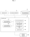
- Fig. 1 is a block diagram illustrating a configuration of a traffic signal recognition device according to the present embodiment.
- the traffic signal recognition device according to the present embodiment includes an imaging unit 71 and a controller 100, and the controller 100 is connected to an imaging unit 71, an in-vehicle sensor 73, a map information acquisition unit 75, and a vehicle control device 400, by a wired or wireless communication path.
- the imaging unit 71, the in-vehicle sensor 73, and the vehicle control device 400 are mounted on a vehicle (not shown), but the map information acquisition unit 75 and the controller 100 may be mounted on the vehicle or may be installed outside the vehicle.
- the imaging unit 71 captures an image of the vehicle in the traveling direction.
- the imaging unit 71 is a digital camera provided with a solid-state image sensor such as a CCD or CMOS, and images the surroundings of the vehicle to capture a digital image of the peripheral region of the vehicle.
- the imaging unit 71 images a predetermined range around the vehicle by setting the focal length, the angle of view of the lens, the vertical and horizontal angles of the camera, and the like.
- the image captured by the imaging unit 71 is output to the controller 100 and stored in a storage unit (not shown) for a predetermined period of time.
- the imaging unit 71 captures images at predetermined time intervals, and the images captured at predetermined time intervals are stored in the storage unit as past images.
- the past image may be deleted after a predetermined period has elapsed from the time when the past image was captured.
- the in-vehicle sensor 73 includes an object detection sensor mounted on the vehicle, such as a laser radar, a millimeter wave radar, and a camera, which detects an object existing around the vehicle.
- the in-vehicle sensor 73 may include a plurality of different types of object detection sensors.
- the in-vehicle sensor 73 detects the environment around the vehicle.
- the in-vehicle sensor 73 may detect a moving object including another vehicle, a motorcycle, a bicycle, a pedestrian, and a stationary object including a stopped vehicle, and the position, posture, size, speed, acceleration, deceleration, and yaw rate, etc. of the moving object and the stationary object with respect to the vehicle.
- the in-vehicle sensor 73 may output, for example, the behavior of a two-dimensional object in a zenith view (also referred to as a plan view) viewed from the air above the vehicle as a detection result.
- a zenith view also referred to as a plan view
- the in-vehicle sensor 73 may detect a sign (a road sign or a sign displayed on the road surface), a guide rail, or the like existing around the vehicle.
- the in-vehicle sensor 73 may detect the slipperiness of the road surface in the lane in which the vehicle is traveling by detecting the rotation speed and the difference in rotation speed of the wheels provided in the vehicle.
- the in-vehicle sensor 73 detects the state of the vehicle in addition to the environment around the vehicle. For example, the in-vehicle sensor 73 may detect the moving speed of the vehicle (moving speed in the front-rear direction, left-right direction, turning speed), the steering angle of the wheels provided in the vehicle, and the changing speed of the steering angle.
- the in-vehicle sensor 73 may measure an absolute position of the vehicle, that is, the position, attitude and speed of the vehicle relative to a given reference point, by using a position detection sensor that measures the absolute position of the vehicle, such as GPS (Global Positioning System) and odometry.
- GPS Global Positioning System
- the map information acquisition unit 75 acquires map information indicating the structure of the road on which the vehicle travels.
- the map information acquired by the map information acquisition unit 75 includes road structure information such as absolute lane positions, lane connection relationships, and relative positional relationships. Further, the map information acquired by the map information acquisition unit 75 may include facility information such as a parking lot and a gas station. In addition, the map information may include the position information of the traffic signal, the type of the traffic signal, the position of the stop line corresponding to the traffic signal, and the like.
- the map information acquisition unit 75 may own a map database that stores the map information, or may acquire the map information from an external map data server by cloud computing. Further, the map information acquisition unit 75 may acquire map information by using vehicle-to-vehicle communication and road-to-vehicle communication.
- the vehicle control device 400 controls a vehicle (not shown) based on the recognition result of the traffic signal obtained by the controller 100.
- the vehicle control device 400 may drive the vehicle by automatic driving according to a predetermined traveling route, or may support the driving operation of the occupants of the vehicle.
- the vehicle control device 400 may be a notification device that notifies the occupants of the vehicle of the recognition result of the traffic signal.
- the controller 100 (an example of a control unit or a processing unit) is a general-purpose microcomputer including a CPU (central processing unit), a memory, and an input / output unit.
- a computer program (traffic signal recognition program) for functioning as a traffic signal recognition device is installed in the controller 100. By executing the computer program, the controller 100 functions as a plurality of information processing circuits (110, 120, 130, 140, 150, 160) included in the traffic signal recognition device.
- a plurality of information processing circuits (110, 120, 130, 140, 150, 160) included in the traffic signal recognition device are realized by software.
- the plurality of information processing circuits (110, 120, 130, 140, 150, 160) may be configured by individual hardware.
- the information processing circuit (110, 120, 130, 140, 150, 160) may also be used as an electronic control unit (ECU) used for other control related to the vehicle.
- ECU electronice control unit
- the controller 100 includes a self-position acquisition unit 110, a stop position acquisition unit 120, a calculation unit 130, a detection area setting unit 140, a determination unit 150, and an output unit 160.
- the self-position acquisition unit 110 acquires the absolute position of the vehicle, that is, the current position of the vehicle with respect to a predetermined reference point, via the in-vehicle sensor 73. In addition, the self-position acquisition unit 110 may acquire the current speed, acceleration, and posture of the vehicle via the in-vehicle sensor 73.
- the stop position acquisition unit 120 searches for the map information acquired by the map information acquisition unit 75 , and extracts a traffic signal located in the traveling direction of the vehicle. Then, the stop position acquisition unit 120 acquires the position of the stop line corresponding to the extracted traffic signal from the map information.
- the stop position acquisition unit 120 may search for the map information acquired by the map information acquisition unit 75 based on the current position and posture of the vehicle acquired by the self-position acquisition unit 110, and may extract a traffic signal located in the traveling direction of the vehicle. Further, the stop position acquisition unit 120 may extract a traffic signal within a range that can be imaged by the imaging unit 71.
- the stop position acquisition unit 120 may extract both a traffic signal and a stop line corresponding to the extracted traffic signal from the image captured by the imaging unit 71, and may acquire the position of the stop line corresponding to the extracted traffic signal by acquiring the position of the traffic signal and the stop line with respect to the vehicle. That is, the position of the stop line corresponding to the traffic signal can be acquired without using the position of the own vehicle or the map information, and the method of acquiring the position of the stop line corresponding to the traffic signal can be changed as appropriate.
- the calculation unit 130 estimates whether or not the vehicle can decelerate at a predetermined deceleration acceleration and can stop before the stop line based on the position of the stop line acquired by the stop position acquisition unit 120. Specifically, the calculation unit 130 calculates the distance D between the current position of the vehicle and the position of the stop line for each extracted traffic signal. Then, the calculation unit 130 calculates the magnitude of the deceleration acceleration ⁇ when the vehicle stops at the stop line by dividing the square of the current speed V of the vehicle by twice the distance D.
- the calculation unit 130 estimates that the vehicle cannot stop before the stop line by decelerating at a predetermined deceleration acceleration ⁇ in a case where the calculated magnitude of the deceleration acceleration ⁇ is larger than the magnitude of the predetermined deceleration acceleration ⁇ .
- the predetermined deceleration acceleration ⁇ is a value obtained by experiments or the like in advance so that the occupants of the vehicle do not feel a sense of discomfort due to sudden deceleration.
- the calculation unit 130 may calculate an expected stop position when the vehicle decelerates at the predetermined deceleration acceleration ⁇ , and may estimate that the vehicle cannot stop before the stop line if the stop line is located between the expected stop position and the vehicle. Specifically, the calculation unit 130 may calculate a predetermined distance DH which the vehicle moves until the vehicle stops by decelerating at the predetermined deceleration acceleration ⁇ , by dividing the square of the current speed V of the vehicle by twice the predetermined deceleration acceleration ⁇ .
- the predetermined distance DH can be evaluated by the following equation (2).
- DH V ⁇ 2 / 2 ⁇
- the calculation unit 130 may set a position advanced by the predetermined distance DH from the current position of the vehicle in the traveling direction of the vehicle as the expected stop position, and may estimate that the vehicle cannot be stopped in front of the stop line in a case where the stop line is located between the expected stop position and the vehicle. That is, in a case where the expected stop position is farther than the stop line along the traveling direction of the vehicle when viewed from the vehicle, the calculation unit 130 may estimate that the vehicle cannot stop before the stop line.
- the calculation unit 130 selects, among the traffic signals extracted by the stop position acquisition unit 120, the traffic signal corresponding to the stop line at which it is estimated that the vehicle cannot stop in front of the vehicle, as a traffic signal (target traffic signal) to be determined.
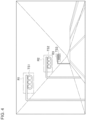
- Fig. 3 is a schematic view showing an example of the positional relationship between the vehicle and the plurality of traffic signals.
- the expected stop position is set in the position PT based on the predetermined distance DH calculated by the above equation (2).
- the vehicle decelerates at the predetermined deceleration acceleration ⁇ it means that the vehicle cannot stop before the stop line at position P1 and the stop line at position P2. This is because the stop line at position P1 and the stop line at position P2 exist in the section between the expected stop position at position PT and the vehicle at position PS.
- the calculation unit 130 selects the traffic signal TS1 corresponding to the stop line at the position P1 and the traffic signal TS2 corresponding to the stop line at the position P2 as the target traffic signals.
- the traffic signal TS3 corresponding to the stop line at position P3 is not selected as the target traffic signal.
- the target traffic signal selected in a case where the calculation unit 130 calculates the deceleration acceleration ⁇ and estimates whether or not the vehicle can be stopped matches the target traffic signal selected in a case where the calculation unit 130 estimates whether or not the vehicle can be stopped based on the positional relationship between the stop line and the expected stop position.
- the detection area setting unit 140 sets a detection area corresponding to the target traffic signal on the image captured by the imaging unit 71.
- the "detection area” means an area in which the target traffic signal is estimated to be present in the image, and is the target range of image processing by the determination unit 150 described later.
- the position of the traffic signal reflected in imaging range in the image can be estimated based on the imaging direction of the imaging unit 71, the position and orientation of the vehicle at the time of imaging, and the position of the traffic signal.
- the detection area setting unit 140 sets, for example, a part of the captured image, which includes the estimated position of the traffic signal in the image, as the detection area.
- Fig. 4 is a schematic diagram showing an example of setting a detection area on the captured image.
- Fig. 4 shows how the detection area R1, the detection area R2, and the detection area R3 are set corresponding to the traffic signal TS1, the traffic signal TS2, and the traffic signal TS3, respectively.
- the detection area R3 corresponding to the traffic signal TS3 is not set.
- the detection area is not set on the image for the traffic signal corresponding to the stop line where the vehicle can decelerate at the predetermined deceleration acceleration and stop in front of, it is possible to reduce the computational load when determining the target traffic signal in the detection area and determining the display state of the target traffic signal.
- the detection area is surely set on the image for the traffic signal corresponding to the stop line where the vehicle cannot stop in front even if the vehicle decelerates at the predetermined deceleration acceleration, it is possible to reliably determine the display state with the traffic signal that needs to be detected as a detection target even if the distance between the intersections is relatively close. Therefore, it is possible to recognize the traffic signal that needs to be detected while suppressing the increase in the computational load.
- the determination unit 150 executes image processing on the detection area, detects the target traffic signal in the detection area, and determines the display state of the target traffic signal.
- the determination unit 150 detects a traffic signal by, for example, template matching.
- template matching a standard traffic signal image is used as a template, and the detection area is scanned while shifting the image one pixel at a time, and for example, the correlation of the brightness distribution is calculated. Then, when the correlation becomes the highest value, it is detected that the traffic signal is at the position on the image where the template is located.
- the "color signal” indicated by the traffic signal includes a “green signal”, a “yellow signal”, and a “red signal”.
- the meaning of "color signal” is determined by the traffic regulations that the vehicle should follow. For example, “green signal” means “may proceed” and “red signal” means “stop at the stop position”.
- the “yellow signal” means “stop at the stop position unless it is not possible to stop safely because it is close to the stop position”.
- Such discrimination of "green signal”, “yellow signal”, and “red signal” may be performed such that it is estimated that the “color signal” having the highest luminance level among the three “color signals” is lit.
- the traffic signal may indicate not only a “color signal” but also an “arrow signal” indicating a direction permitted to the vehicle at an intersection where the traffic signal is installed.
- the "arrow signal” is a "right turn signal”, a "straight ahead signal”, and/or a "left turn signal”.
- the “arrow signal” is not limited to the “right turn signal”, “straight ahead signal”, and “left turn signal”, and various variations can be considered depending on the structure of the intersection where the traffic signal is installed.
- the meaning of the "arrow signal” is determined by the traffic regulations that the vehicle should obey.
- the determination unit 150 executes image processing on the detection area and determines a lighting state of the "color signal” and the “arrow signal” of the traffic signal as the display state of the traffic signal.
- the image processing of the traffic signal detection by the determination unit 150 may use machine learning such as a support vector machine or a neural network.
- machine learning such as a support vector machine or a neural network.
- the recognition rate can be improved by preparing a learning database in which templates of traffic signals of different sizes are stored in advance and using the learning database to be referred to according to the distance to the traffic signal.
- the output unit 160 outputs the display state of the target traffic signal determined by the determination unit 150.
- the display state of the target traffic signal is output from the output unit 160 to the vehicle control device 400 and used for controlling the vehicle.
- the display state of the target traffic signal may be output from the output unit 160 to a notification device (not shown) and notified to the occupant via the notification device.
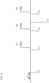
- the traffic signal recognition process shown in Fig. 2 may be executed every time the imaging unit 71 acquires an image, or may be executed every cycle the image processing is executed on the detection area after the imaging unit 71 acquires the image.
- step S101 the self-position acquisition unit 110 acquires the absolute position of the vehicle via the in-vehicle sensor 73.
- step S103 the stop position acquisition unit 120 searches for the map information acquired by the map information acquisition unit 75, and extracts a traffic signal located in the traveling direction of the vehicle.
- step S105 the stop position acquisition unit 120 acquires the position of the stop line corresponding to the extracted traffic signal from the map information.
- step S107 the calculation unit 130 calculates a selection condition for selecting a target traffic signal from the extracted traffic signals. Specifically, in a case of estimating whether or not the vehicle can decelerate at a predetermined deceleration acceleration and stop before the stop line, the calculation unit 130 calculates the magnitude of the deceleration acceleration ⁇ in a case where the vehicle stops at the stop line. Further, in a case of estimating whether or not the vehicle can be stopped based on the positional relationship between the stop line and the expected stop position, the calculation unit 130 calculates a predetermined distance DH in which the vehicle decelerates at a predetermined deceleration acceleration ⁇ and moves until the vehicle stops.
- step S109 the calculation unit 130 selects a target traffic signal from the extracted traffic signals using the calculated selection conditions. In the following, it will be described assuming that N target traffic signals are selected.
- the calculation unit 130 estimates that the vehicle cannot stop before the stop line when the vehicle decelerates at the predetermined deceleration acceleration ⁇ , and selects a traffic signal corresponding to the stop line as the target traffic signal.
- the calculation unit 130 may select a traffic signal corresponding to a stop line as the target traffic signal, wherein the distance D between the vehicle and the stop line is smaller than the calculated predetermined distance DH.
- step S111 the detection area setting unit 140 sets the detection area corresponding to the target traffic signal on the image captured by the imaging unit 71.
- step S121 the determination unit 150 sets the variable i to 1.
- step S123 the determination unit 150 determines the display state of the target traffic signal (i-th target traffic signal) closest to the vehicle among the N target traffic signals. Specifically, image processing is executed on the detection area corresponding to the i-th target traffic signal closest to the vehicle, and the determination unit 150 determines the display state of the target traffic signal.
- step S127 the determination unit 150 determines whether or not it is possible to go straight on the stop line (it is possible to go straight) corresponding to the i-th target traffic signal based on the display state of the i-th target traffic signal.
- the determination unit 150 may determine whether or not the vehicle can go straight based on the travel plan of the vehicle instead of based on the display state of the target traffic signal. Specifically, based on the vehicle's travel plan, if the vehicle does not go straight and turns left or right at an intersection located in front of the i-th target traffic signal, the vehicle will not pass through the stop line corresponding to the i-th target traffic signal. In this case, the determination unit 150 may determine that the vehicle cannot go straight at the i-th target traffic signal.
- step S127 If it is determined that "the vehicle can go straight" in step S127 (YES in step S127), the process proceeds to step S129, and the determination unit 150 adds 1 to the variable i.
- step S127 If it is determined that "the vehicle cannot go straight” in step S127 (NO in step S127), the process proceeds to step S131.
- step S131 the output unit 160 outputs the display state of the target traffic signal determined by the determination unit 150.
- the output display state of the target traffic signal is used, for example, in the vehicle control device 400.
- the determination unit 150 determines whether or not "the vehicle can go straight" at the i-th target traffic signal based on the display state of the i-th target traffic signal after the detection area setting unit 140 sets the detection area corresponding to the target traffic signal on the image. It is explained that the determination unit 150 does not determine whether or not "the vehicle can go straight” at the display state for the (i+1)-th and subsequent target traffic signals in a case where it is determined that "the vehicle cannot go straight" at the i-th target traffic signal.
- this embodiment is not limited to the example shown in the flowchart of Fig. 2 .
- it may be determined whether or not "the vehicle can go straight" based on the display state of the i-th target traffic signal, and in the case where it is determined that "the vehicle cannot go straight" at the i-th target traffic signal, the detection area corresponding to the (i+1)-th and subsequent target traffic signals may not be set. Since the number of detection areas set on the image can be reduced, the computational load on the detection area setting unit 140 and the determination unit 150 can be reduced.
- the detection area setting unit 140 may set the detection area corresponding to the target traffic signal on the image when the vehicle is accelerating or moving at a constant velocity, and may not set the detection area corresponding to the target traffic signal on the image when the vehicle is decelerating.
- the vehicle is decelerating, it is assumed that the vehicle will stop at the stop line closest to the vehicle, and it is considered that there is little need to consider a traffic signal corresponding to a stop line distant from the vehicle. Therefore, when the vehicle is decelerating, the computational load can be reduced by not setting the detection area corresponding to the target traffic signal.
- a traffic signal recognition method of claim 1 and a traffic signal recognition device of claim 9 it is possible to determine the display state of the target traffic signal corresponding to the stop line at which the vehicle cannot be stopped even if the vehicle decelerates at the predetermined deceleration acceleration, and it is possible to safely decelerate and/or stop the vehicle by outputting the display state.
- the detection area is surely set on the image for the traffic signal corresponding to the stop line which the vehicle cannot stop in front of even if the vehicle decelerates at the predetermined deceleration acceleration, and thus, it is possible to reliably determine the display state with the traffic signal that needs to be detected as a detection target, even if the distance between intersections is relatively close. As a result, the safety of the vehicle can be improved.
- the detection area is not set on the image for the traffic signal corresponding to the stop line which the vehicle can stop in front of by decelerating at the predetermined deceleration acceleration, it is possible to reduce the computational load when detecting the target traffic signal in the detection area and determining the display state of the target traffic signal.
- the target traffic signal can be reliably selected with reference to the predetermined deceleration acceleration.
- the target traffic signal can be reliably selected with reference to the expected stop position determined based on the predetermined deceleration acceleration.
- the target traffic signal can be reliably selected based on the position of the traffic signal included in the map information.
- the number of detection areas set on the image can be reduced, so that the computational load can be reduced.
- the traffic signal that needs to be detected can be selected as the target traffic signal and it is possible to perform determining the display state of the traffic signal that needs to be detected. As a result, the safety of the vehicle can be improved.
- the computational load can be reduced by not setting the detection area corresponding to the target traffic signal.
- a computational load related to image processing tends to be larger than a computational load for acquiring the position of the vehicle, the speed of the vehicle, and the position of the stop line, and a computational load for estimating the stop of the vehicle before the stop line.
- the number of estimations for stopping the vehicle before the stop line can be reduced, and the computational load can be reduced.
- Respective functions described in the above embodiment may be implemented by one or plural processing circuits.
- the processing circuits include programmed processing devices such as a processing device including an electric circuit and include devices such as an application specific integrated circuit (ASIC) and conventional circuit elements that are arranged to execute the functions described in the embodiment.
- ASIC application specific integrated circuit
Landscapes
- Engineering & Computer Science (AREA)
- Physics & Mathematics (AREA)
- General Physics & Mathematics (AREA)
- Theoretical Computer Science (AREA)
- Multimedia (AREA)
- Radar, Positioning & Navigation (AREA)
- Remote Sensing (AREA)
- Automation & Control Theory (AREA)
- Mechanical Engineering (AREA)
- Computer Vision & Pattern Recognition (AREA)
- Transportation (AREA)
- Databases & Information Systems (AREA)
- Health & Medical Sciences (AREA)
- Artificial Intelligence (AREA)
- Computing Systems (AREA)
- Human Computer Interaction (AREA)
- Evolutionary Computation (AREA)
- General Health & Medical Sciences (AREA)
- Medical Informatics (AREA)
- Software Systems (AREA)
- Traffic Control Systems (AREA)
- Control Of Driving Devices And Active Controlling Of Vehicle (AREA)
Claims (9)
- Verfahren für Erkennung von Verkehrssignalen, das umfasst:Aufnehmen eines Bildes einer Fahrtrichtung eines Fahrzeugs unter Verwendung einer an dem Fahrzeug installierten Bilderzeugungs-Einheit (71),Ermitteln von Positionen (P1, P2, P3) von Haltelinien, die jeweils einem in der Fahrtrichtung des Fahrzeugs befindlichen Verkehrssignal (TS1, TS2, TS3) entsprechen, Schätzen, ob das Fahrzeug mit einer vorgegebenen Verlangsamung abgebremst werden und vor den Haltelinien anhalten kann, auf Basis der Positionen (P1, P2, P3) der Haltelinien,Auswählen derjenigen Verkehrssignale (TS1, TS2), die den Haltelinien entsprechen, vor denen das Fahrzeug schätzungsweise nicht anhalten kann, als Ziel-Verkehrssignal (TS1, TS2),Schätzen einer Ziel-Position des Ziel-Verkehrssignals (TS1, TS2) in dem Bild,Einstellen eines Teils des Bildes, der die Ziel-Position des Ziel-Verkehrssignals (TS1, TS2) enthält, in dem Bild als einen Erfassungsbereich, ohne dass ein Erfassungsbereich in dem Bild eingestellt wird, der Verkehrssignalen (TS3) entspricht, die sich von dem Ziel-Verkehrssignal (TS1, TS2) unterscheiden, undBestimmen eines Anzeigezustandes des Ziel-Verkehrssignals (TS1, TS2) durch Ausführen von Bildverarbeitung an dem eingestellten Erfassungsbereich.
- Verfahren für Erkennung von Verkehrssignalen nach Anspruch 1, das des Weiteren umfasst:Berechnen einer Verlangsamung, bei der das Fahrzeug an jeder der Haltelinien anhält, undSchätzen, dass das Fahrzeug nicht vor der Haltelinie anhalten kann, wenn ein Betrag der Verlangsamung größer ist als ein Betrag der vorgegebenen Verlangsamung.
- Verfahren für Erkennung von Verkehrssignalen nach Anspruch 1 oder 2, das des Weiteren umfasst:Berechnen einer erwarteten Anhalte-Position (PT), wenn das Fahrzeug mit der vorgegebenen Verlangsamung abbremst, undSchätzen, dass das Fahrzeug nicht vor den Haltelinien anhalten kann, wenn sich die Haltelinien zwischen der erwarteten Anhalte-Position (PT) und dem Fahrzeug befinden.
- Verfahren für Erkennung von Verkehrssignalen nach einem der Ansprüche 1 bis 3, das des Weiteren umfasst:
Ermitteln der Positionen (P1, P2, P3) der Haltelinien, die den Verkehrssignalen (TS1, TS2, TS3) entsprechen, auf Basis einer Position des Fahrzeugs und einer Karten-information, wobei die Karten-Information Informationen über die Positionen (P1, P2, P3) der Verkehrssignale (TS1, TS2, TS3) enthält. - Verfahren für Erkennung von Verkehrssignalen nach einem der Ansprüche 1 bis 4, das des Weiteren umfasst:
Einstellen des Erfassungsbereiches, der dem Ziel-Verkehrssignal entspricht, auf dem Bild, wenn alle Verkehrssignale (TS1, TS2, TS3) zwischen der dem Ziel-Verkehrssignal entsprechenden Haltelinie und dem Fahrzeug anzeigen, dass das Fahrzeug auf einer geplanten Fahrtroute des Fahrzeugs geradeaus fahren kann. - Verfahren für Erkennung von Verkehrssignalen nach einem der Ansprüche 1 bis 5, das des Weiteren umfasst:
Ermitteln einer Beschleunigung des Fahrzeugs und Einstellen des dem Ziel-Verkehrssignal entsprechenden Erfassungsbereiches auf dem Bild, wenn das Fahrzeug beschleunigt oder sich mit konstanter Geschwindigkeit bewegt. - Verfahren für Erkennung von Verkehrssignalen nach einem der Ansprüche 1 bis 6, das des Weiteren umfasst:Ermitteln einer Position des Fahrzeugs, einer Geschwindigkeit des Fahrzeugs und der Position der Haltelinie für jeden Zyklus des Ausführens der Bildverarbeitung, undSchätzen, ob das Fahrzeug vor der Haltelinie anhalten kann.
- Verfahren für Erkennung von Verkehrssignalen nach einem der Ansprüche 1 bis 7, das des Weiteren umfasst:
Schätzen, ob das Fahrzeug durch Abbremsen des Fahrzeugs mit der vorgegebenen Verlangsamung vor der Haltelinie anhalten kann, wenn alle Verkehrssignale (TS1, TS2, TS3) zwischen der Haltelinie und dem Fahrzeug anzeigen, dass das Fahrzeug auf einer geplanten Fahrtroute des Fahrzeugs geradeaus fahren kann. - Vorrichtung für Erkennung von Verkehrssignalen, die eine an einem Fahrzeug installierte Bilderzeugungs-Einheit (71) sowie eine Steuerungseinrichtung (100) umfasst, wobei die Steuerungseinrichtung (100) durchführt:Aufnehmen eines Bildes einer Fahrtrichtung eines Fahrzeugs unter Verwendung der Bilderzeugungs-Einheit (71),Ermitteln von Positionen (P1, P2, P3) von Haltelinien, die jeweils einem in der Fahrtrichtung des Fahrzeugs befindlichen Verkehrssignal (TS1, TS2, TS3) entsprechen, Schätzen, ob das Fahrzeug mit einer vorgegebenen Verlangsamung abgebremst werden und vor den Haltelinien anhalten kann, auf Basis der Positionen (P1, P2, P3) der Haltelinien,Auswählen derjenigen Verkehrssignale (TS1, TS2, TS3), die den Haltelinien entsprechen, vor denen das Fahrzeug schätzungsweise nicht anhalten kann, als Ziel-Verkehrssignal (TS1, TS2),Schätzen einer Ziel-Position des Ziel-Signals (TS1, TS2) in dem Bild,Einstellen eines Teils des Bildes, der die Ziel-Position des Ziel-Verkehrssignals (TS1, TS2) enthält, in dem Bild als einen Erfassungsbereich, ohne dass ein Erfassungsbereich in dem Bild eingestellt wird, der Verkehrssignalen (TS3) entspricht, die sich von dem Ziel-Verkehrssignal (TS1, TS2) unterscheiden, sowieBestimmen eines Anzeigezustandes des Ziel-Verkehrssignals (TS1, TS2) durch Ausführen von Bildverarbeitung an dem eingestellten Erfassungsbereich.
Applications Claiming Priority (1)
| Application Number | Priority Date | Filing Date | Title |
|---|---|---|---|
| PCT/IB2019/001266 WO2021094799A1 (ja) | 2019-11-12 | 2019-11-12 | 信号機認識方法及び信号機認識装置 |
Publications (3)
| Publication Number | Publication Date |
|---|---|
| EP4060643A1 EP4060643A1 (de) | 2022-09-21 |
| EP4060643A4 EP4060643A4 (de) | 2022-10-26 |
| EP4060643B1 true EP4060643B1 (de) | 2024-02-28 |
Family
ID=75911352
Family Applications (1)
| Application Number | Title | Priority Date | Filing Date |
|---|---|---|---|
| EP19952384.6A Active EP4060643B1 (de) | 2019-11-12 | 2019-11-12 | Verfahren und vorrichtung zur verkehrssignalerkennung |
Country Status (7)
| Country | Link |
|---|---|
| US (1) | US11769337B2 (de) |
| EP (1) | EP4060643B1 (de) |
| JP (1) | JP7226583B2 (de) |
| CN (1) | CN114746923B (de) |
| BR (1) | BR112022008335A2 (de) |
| MX (1) | MX2022005598A (de) |
| WO (1) | WO2021094799A1 (de) |
Families Citing this family (1)
| Publication number | Priority date | Publication date | Assignee | Title |
|---|---|---|---|---|
| CN114743395B (zh) * | 2022-03-21 | 2024-03-08 | 中汽创智科技有限公司 | 一种信号灯检测方法、装置、设备及介质 |
Citations (4)
| Publication number | Priority date | Publication date | Assignee | Title |
|---|---|---|---|---|
| JP2007241469A (ja) * | 2006-03-06 | 2007-09-20 | Toyota Motor Corp | 画像処理システム |
| JP2011145892A (ja) * | 2010-01-14 | 2011-07-28 | Fuji Heavy Ind Ltd | 運転支援装置 |
| US20170177958A1 (en) * | 2014-05-20 | 2017-06-22 | Nissan Motor Co., Ltd. | Target Detection Apparatus and Target Detection Method |
| US20170355375A1 (en) * | 2012-03-26 | 2017-12-14 | Waymo Llc | Robust Method for Detecting Traffic Signals and their Associated States |
Family Cites Families (25)
| Publication number | Priority date | Publication date | Assignee | Title |
|---|---|---|---|---|
| JP5729176B2 (ja) * | 2011-07-01 | 2015-06-03 | アイシン・エィ・ダブリュ株式会社 | 移動案内システム、移動案内装置、移動案内方法及びコンピュータプログラム |
| JP5591308B2 (ja) * | 2012-11-08 | 2014-09-17 | 本田技研工業株式会社 | 車両用運転支援装置 |
| JP6112054B2 (ja) * | 2014-01-31 | 2017-04-12 | 株式会社Jvcケンウッド | 電子機器、電子機器の制御方法及び電子機器の制御プログラム |
| JP6547292B2 (ja) * | 2014-02-05 | 2019-07-24 | 株式会社リコー | 画像処理装置、機器制御システム、および画像処理プログラム |
| JP2016134033A (ja) * | 2015-01-20 | 2016-07-25 | 住友電気工業株式会社 | 運転支援装置、コンピュータプログラム及び運転支援方法 |
| US9715827B2 (en) * | 2015-04-01 | 2017-07-25 | Misapplied Sciences, Inc. | Multi-view traffic signage |
| EP3306589B1 (de) * | 2015-06-05 | 2019-01-09 | Nissan Motor Co., Ltd. | Verkehrssignaldetektionsvorrichtung und verkehrssignaldetektionsverfahren |
| BR112018000191B1 (pt) | 2015-07-13 | 2023-02-14 | Nissan Motor Co., Ltd | Dispositivo de reconhecimento de semáforo e método de reconhecidmento de semáforo |
| US20170024622A1 (en) * | 2015-07-24 | 2017-01-26 | Honda Motor Co., Ltd. | Surrounding environment recognition device |
| US9747508B2 (en) * | 2015-07-24 | 2017-08-29 | Honda Motor Co., Ltd. | Surrounding environment recognition device |
| US10275669B2 (en) * | 2015-09-09 | 2019-04-30 | Lightmetrics Technologies Pvt. Ltd. | System and method for detecting objects in an automotive environment |
| JP6651796B2 (ja) * | 2015-11-09 | 2020-02-19 | トヨタ自動車株式会社 | 運転支援装置 |
| JP2017138702A (ja) | 2016-02-02 | 2017-08-10 | トヨタ自動車株式会社 | 信号通過支援装置 |
| SG10201912533UA (en) * | 2016-03-31 | 2020-02-27 | Agency Science Tech & Res | Signal light detection |
| CN107622683B (zh) * | 2016-07-15 | 2020-04-17 | 郑州宇通客车股份有限公司 | 自主驾驶车辆的路口通行方法及系统 |
| JP6834425B2 (ja) | 2016-12-02 | 2021-02-24 | スズキ株式会社 | 運転支援装置 |
| JP2018106294A (ja) * | 2016-12-22 | 2018-07-05 | 株式会社オートネットワーク技術研究所 | 車載装置及びコンピュータプログラム |
| US10300894B2 (en) * | 2017-03-13 | 2019-05-28 | Denso International America, Inc. | Auto-braking system for vehicle and method for auto-braking vehicle |
| JP2019079126A (ja) * | 2017-10-20 | 2019-05-23 | トヨタ自動車株式会社 | 車両 |
| JP2019079398A (ja) * | 2017-10-26 | 2019-05-23 | トヨタ自動車株式会社 | 走行制御装置 |
| KR20190078664A (ko) * | 2017-12-11 | 2019-07-05 | 삼성전자주식회사 | 컨텐츠를 표시하기 위한 장치 및 방법 |
| JP2019156192A (ja) * | 2018-03-14 | 2019-09-19 | 本田技研工業株式会社 | 車両制御装置 |
| CN109263659A (zh) * | 2018-07-28 | 2019-01-25 | 上海商汤智能科技有限公司 | 智能驾驶控制方法和装置、车辆、电子设备、介质、产品 |
| JP7151633B2 (ja) * | 2019-06-12 | 2022-10-12 | トヨタ自動車株式会社 | 情報表示装置 |
| JP7167880B2 (ja) * | 2019-08-27 | 2022-11-09 | トヨタ自動車株式会社 | 停止線位置推定装置及び車両制御システム |
-
2019
- 2019-11-12 BR BR112022008335A patent/BR112022008335A2/pt unknown
- 2019-11-12 US US17/775,521 patent/US11769337B2/en active Active
- 2019-11-12 JP JP2021555892A patent/JP7226583B2/ja active Active
- 2019-11-12 CN CN201980102187.7A patent/CN114746923B/zh active Active
- 2019-11-12 WO PCT/IB2019/001266 patent/WO2021094799A1/ja unknown
- 2019-11-12 EP EP19952384.6A patent/EP4060643B1/de active Active
- 2019-11-12 MX MX2022005598A patent/MX2022005598A/es unknown
Patent Citations (4)
| Publication number | Priority date | Publication date | Assignee | Title |
|---|---|---|---|---|
| JP2007241469A (ja) * | 2006-03-06 | 2007-09-20 | Toyota Motor Corp | 画像処理システム |
| JP2011145892A (ja) * | 2010-01-14 | 2011-07-28 | Fuji Heavy Ind Ltd | 運転支援装置 |
| US20170355375A1 (en) * | 2012-03-26 | 2017-12-14 | Waymo Llc | Robust Method for Detecting Traffic Signals and their Associated States |
| US20170177958A1 (en) * | 2014-05-20 | 2017-06-22 | Nissan Motor Co., Ltd. | Target Detection Apparatus and Target Detection Method |
Also Published As
| Publication number | Publication date |
|---|---|
| WO2021094799A1 (ja) | 2021-05-20 |
| EP4060643A1 (de) | 2022-09-21 |
| US20220375233A1 (en) | 2022-11-24 |
| MX2022005598A (es) | 2023-04-18 |
| JP7226583B2 (ja) | 2023-02-21 |
| CN114746923B (zh) | 2024-05-14 |
| CN114746923A (zh) | 2022-07-12 |
| US11769337B2 (en) | 2023-09-26 |
| JPWO2021094799A1 (de) | 2021-05-20 |
| BR112022008335A2 (pt) | 2022-07-26 |
| EP4060643A4 (de) | 2022-10-26 |
Similar Documents
| Publication | Publication Date | Title |
|---|---|---|
| US9809223B2 (en) | Driving assistant for vehicles | |
| KR101276871B1 (ko) | 차량 충돌 방지 장치 및 방법 | |
| US9922259B2 (en) | Traffic light detection device and traffic light detection method | |
| CN109841088B (zh) | 车辆驾驶辅助系统及方法 | |
| JP5363921B2 (ja) | 車両用白線認識装置 | |
| JP6911312B2 (ja) | 物体識別装置 | |
| US20210001856A1 (en) | Vehicle control device and vehicle control method | |
| EP3961580A1 (de) | Vorrichtung, verfahren und computerprogramm zur objektdetektion | |
| JP2022142165A (ja) | 車両制御装置、車両制御方法及び車両制御用コンピュータプログラム | |
| CN114728657A (zh) | 车辆控制方法及车辆控制装置 | |
| CN114103954A (zh) | 行驶车道计划装置、存储介质以及行驶车道计划方法 | |
| EP4060643B1 (de) | Verfahren und vorrichtung zur verkehrssignalerkennung | |
| EP4060640B1 (de) | Verfahren und vorrichtung zur verkehrssignalerkennung | |
| CN114973644B (zh) | 道路信息生成装置 | |
| US11663834B2 (en) | Traffic signal recognition method and traffic signal recognition device | |
| JP7435513B2 (ja) | 車両制御装置及び車両制御方法 | |
| JP7334107B2 (ja) | 車両制御方法及び車両制御装置 | |
| RU2779773C1 (ru) | Способ распознавания светофора и устройство распознавания светофора | |
| JP7149171B2 (ja) | 物体認識方法及び物体認識装置 | |
| US20220254056A1 (en) | Distance calculation apparatus and vehicle position estimation apparatus | |
| JP2023094930A (ja) | 挙動予測方法及び挙動予測装置 | |
| CN116264036A (zh) | 车辆用控制装置 |
Legal Events
| Date | Code | Title | Description |
|---|---|---|---|
| STAA | Information on the status of an ep patent application or granted ep patent |
Free format text: STATUS: THE INTERNATIONAL PUBLICATION HAS BEEN MADE |
|
| PUAI | Public reference made under article 153(3) epc to a published international application that has entered the european phase |
Free format text: ORIGINAL CODE: 0009012 |
|
| STAA | Information on the status of an ep patent application or granted ep patent |
Free format text: STATUS: REQUEST FOR EXAMINATION WAS MADE |
|
| 17P | Request for examination filed |
Effective date: 20220610 |
|
| AK | Designated contracting states |
Kind code of ref document: A1 Designated state(s): AL AT BE BG CH CY CZ DE DK EE ES FI FR GB GR HR HU IE IS IT LI LT LU LV MC MK MT NL NO PL PT RO RS SE SI SK SM TR |
|
| A4 | Supplementary search report drawn up and despatched |
Effective date: 20220928 |
|
| RIC1 | Information provided on ipc code assigned before grant |
Ipc: B60W 30/08 20120101ALI20220922BHEP Ipc: B60W 50/14 20200101ALI20220922BHEP Ipc: G08G 1/0968 20060101ALI20220922BHEP Ipc: G08G 1/0962 20060101ALI20220922BHEP Ipc: G08G 1/16 20060101AFI20220922BHEP |
|
| DAV | Request for validation of the european patent (deleted) | ||
| DAX | Request for extension of the european patent (deleted) | ||
| STAA | Information on the status of an ep patent application or granted ep patent |
Free format text: STATUS: EXAMINATION IS IN PROGRESS |
|
| 17Q | First examination report despatched |
Effective date: 20230406 |
|
| GRAP | Despatch of communication of intention to grant a patent |
Free format text: ORIGINAL CODE: EPIDOSNIGR1 |
|
| STAA | Information on the status of an ep patent application or granted ep patent |
Free format text: STATUS: GRANT OF PATENT IS INTENDED |
|
| RIC1 | Information provided on ipc code assigned before grant |
Ipc: G06V 20/58 20220101ALI20230814BHEP Ipc: G06V 10/75 20220101ALI20230814BHEP Ipc: G06V 20/56 20220101ALI20230814BHEP Ipc: B60W 30/18 20120101ALI20230814BHEP Ipc: B60W 50/14 20200101ALI20230814BHEP Ipc: G08G 1/0968 20060101ALI20230814BHEP Ipc: G08G 1/0962 20060101ALI20230814BHEP Ipc: G08G 1/16 20060101AFI20230814BHEP |
|
| GRAJ | Information related to disapproval of communication of intention to grant by the applicant or resumption of examination proceedings by the epo deleted |
Free format text: ORIGINAL CODE: EPIDOSDIGR1 |
|
| STAA | Information on the status of an ep patent application or granted ep patent |
Free format text: STATUS: EXAMINATION IS IN PROGRESS |
|
| INTG | Intention to grant announced |
Effective date: 20230904 |
|
| GRAP | Despatch of communication of intention to grant a patent |
Free format text: ORIGINAL CODE: EPIDOSNIGR1 |
|
| STAA | Information on the status of an ep patent application or granted ep patent |
Free format text: STATUS: GRANT OF PATENT IS INTENDED |
|
| INTC | Intention to grant announced (deleted) | ||
| INTG | Intention to grant announced |
Effective date: 20231018 |
|
| GRAS | Grant fee paid |
Free format text: ORIGINAL CODE: EPIDOSNIGR3 |
|
| GRAA | (expected) grant |
Free format text: ORIGINAL CODE: 0009210 |
|
| STAA | Information on the status of an ep patent application or granted ep patent |
Free format text: STATUS: THE PATENT HAS BEEN GRANTED |
|
| AK | Designated contracting states |
Kind code of ref document: B1 Designated state(s): AL AT BE BG CH CY CZ DE DK EE ES FI FR GB GR HR HU IE IS IT LI LT LU LV MC MK MT NL NO PL PT RO RS SE SI SK SM TR |
|
| REG | Reference to a national code |
Ref country code: GB Ref legal event code: FG4D |
|
| REG | Reference to a national code |
Ref country code: CH Ref legal event code: EP |
|
| REG | Reference to a national code |
Ref country code: DE Ref legal event code: R096 Ref document number: 602019047593 Country of ref document: DE |
|
| REG | Reference to a national code |
Ref country code: IE Ref legal event code: FG4D |