EP4056830B1 - Startverfahren für fahrzeugmotor, serielles hybridfahrzeug und startvorrichtung für fahrzeugmotor - Google Patents
Startverfahren für fahrzeugmotor, serielles hybridfahrzeug und startvorrichtung für fahrzeugmotor Download PDFInfo
- Publication number
- EP4056830B1 EP4056830B1 EP19951238.5A EP19951238A EP4056830B1 EP 4056830 B1 EP4056830 B1 EP 4056830B1 EP 19951238 A EP19951238 A EP 19951238A EP 4056830 B1 EP4056830 B1 EP 4056830B1
- Authority
- EP
- European Patent Office
- Prior art keywords
- engine
- hub
- ignition
- torque
- vehicle
- Prior art date
- Legal status (The legal status is an assumption and is not a legal conclusion. Google has not performed a legal analysis and makes no representation as to the accuracy of the status listed.)
- Active
Links
Images


Classifications
-
- F—MECHANICAL ENGINEERING; LIGHTING; HEATING; WEAPONS; BLASTING
- F02—COMBUSTION ENGINES; HOT-GAS OR COMBUSTION-PRODUCT ENGINE PLANTS
- F02N—STARTING OF COMBUSTION ENGINES; STARTING AIDS FOR SUCH ENGINES, NOT OTHERWISE PROVIDED FOR
- F02N11/00—Starting of engines by means of electric motors
- F02N11/08—Circuits specially adapted for starting of engines
- F02N11/0859—Circuits specially adapted for starting of engines specially adapted to the type of the starter motor or integrated into it
-
- F—MECHANICAL ENGINEERING; LIGHTING; HEATING; WEAPONS; BLASTING
- F02—COMBUSTION ENGINES; HOT-GAS OR COMBUSTION-PRODUCT ENGINE PLANTS
- F02N—STARTING OF COMBUSTION ENGINES; STARTING AIDS FOR SUCH ENGINES, NOT OTHERWISE PROVIDED FOR
- F02N11/00—Starting of engines by means of electric motors
- F02N11/04—Starting of engines by means of electric motors the motors being associated with current generators
-
- B—PERFORMING OPERATIONS; TRANSPORTING
- B60—VEHICLES IN GENERAL
- B60K—ARRANGEMENT OR MOUNTING OF PROPULSION UNITS OR OF TRANSMISSIONS IN VEHICLES; ARRANGEMENT OR MOUNTING OF PLURAL DIVERSE PRIME-MOVERS IN VEHICLES; AUXILIARY DRIVES FOR VEHICLES; INSTRUMENTATION OR DASHBOARDS FOR VEHICLES; ARRANGEMENTS IN CONNECTION WITH COOLING, AIR INTAKE, GAS EXHAUST OR FUEL SUPPLY OF PROPULSION UNITS IN VEHICLES
- B60K6/00—Arrangement or mounting of plural diverse prime-movers for mutual or common propulsion, e.g. hybrid propulsion systems comprising electric motors and internal combustion engines
- B60K6/20—Arrangement or mounting of plural diverse prime-movers for mutual or common propulsion, e.g. hybrid propulsion systems comprising electric motors and internal combustion engines the prime-movers consisting of electric motors and internal combustion engines, e.g. HEVs
- B60K6/42—Arrangement or mounting of plural diverse prime-movers for mutual or common propulsion, e.g. hybrid propulsion systems comprising electric motors and internal combustion engines the prime-movers consisting of electric motors and internal combustion engines, e.g. HEVs characterised by the architecture of the hybrid electric vehicle
- B60K6/44—Series-parallel type
- B60K6/442—Series-parallel switching type
-
- B—PERFORMING OPERATIONS; TRANSPORTING
- B60—VEHICLES IN GENERAL
- B60W—CONJOINT CONTROL OF VEHICLE SUB-UNITS OF DIFFERENT TYPE OR DIFFERENT FUNCTION; CONTROL SYSTEMS SPECIALLY ADAPTED FOR HYBRID VEHICLES; ROAD VEHICLE DRIVE CONTROL SYSTEMS FOR PURPOSES NOT RELATED TO THE CONTROL OF A PARTICULAR SUB-UNIT
- B60W10/00—Conjoint control of vehicle sub-units of different type or different function
- B60W10/04—Conjoint control of vehicle sub-units of different type or different function including control of propulsion units
- B60W10/06—Conjoint control of vehicle sub-units of different type or different function including control of propulsion units including control of combustion engines
-
- F—MECHANICAL ENGINEERING; LIGHTING; HEATING; WEAPONS; BLASTING
- F02—COMBUSTION ENGINES; HOT-GAS OR COMBUSTION-PRODUCT ENGINE PLANTS
- F02D—CONTROLLING COMBUSTION ENGINES
- F02D29/00—Controlling engines, such controlling being peculiar to the devices driven thereby, the devices being other than parts or accessories essential to engine operation, e.g. controlling of engines by signals external thereto
- F02D29/06—Controlling engines, such controlling being peculiar to the devices driven thereby, the devices being other than parts or accessories essential to engine operation, e.g. controlling of engines by signals external thereto peculiar to engines driving electric generators
-
- F—MECHANICAL ENGINEERING; LIGHTING; HEATING; WEAPONS; BLASTING
- F02—COMBUSTION ENGINES; HOT-GAS OR COMBUSTION-PRODUCT ENGINE PLANTS
- F02N—STARTING OF COMBUSTION ENGINES; STARTING AIDS FOR SUCH ENGINES, NOT OTHERWISE PROVIDED FOR
- F02N11/00—Starting of engines by means of electric motors
- F02N11/08—Circuits specially adapted for starting of engines
- F02N11/0862—Circuits specially adapted for starting of engines characterised by the electrical power supply means, e.g. battery
-
- F—MECHANICAL ENGINEERING; LIGHTING; HEATING; WEAPONS; BLASTING
- F02—COMBUSTION ENGINES; HOT-GAS OR COMBUSTION-PRODUCT ENGINE PLANTS
- F02P—IGNITION, OTHER THAN COMPRESSION IGNITION, FOR INTERNAL-COMBUSTION ENGINES; TESTING OF IGNITION TIMING IN COMPRESSION-IGNITION ENGINES
- F02P5/00—Advancing or retarding ignition; Control therefor
- F02P5/04—Advancing or retarding ignition; Control therefor automatically, as a function of the working conditions of the engine or vehicle or of the atmospheric conditions
- F02P5/145—Advancing or retarding ignition; Control therefor automatically, as a function of the working conditions of the engine or vehicle or of the atmospheric conditions using electrical means
- F02P5/15—Digital data processing
- F02P5/1502—Digital data processing using one central computing unit
- F02P5/1506—Digital data processing using one central computing unit with particular means during starting
-
- F—MECHANICAL ENGINEERING; LIGHTING; HEATING; WEAPONS; BLASTING
- F16—ENGINEERING ELEMENTS AND UNITS; GENERAL MEASURES FOR PRODUCING AND MAINTAINING EFFECTIVE FUNCTIONING OF MACHINES OR INSTALLATIONS; THERMAL INSULATION IN GENERAL
- F16F—SPRINGS; SHOCK-ABSORBERS; MEANS FOR DAMPING VIBRATION
- F16F15/00—Suppression of vibrations in systems; Means or arrangements for avoiding or reducing out-of-balance forces, e.g. due to motion
- F16F15/10—Suppression of vibrations in rotating systems by making use of members moving with the system
- F16F15/12—Suppression of vibrations in rotating systems by making use of members moving with the system using elastic members or friction-damping members, e.g. between a rotating shaft and a gyratory mass mounted thereon
- F16F15/121—Suppression of vibrations in rotating systems by making use of members moving with the system using elastic members or friction-damping members, e.g. between a rotating shaft and a gyratory mass mounted thereon using springs as elastic members, e.g. metallic springs
- F16F15/1217—Motion-limiting means, e.g. means for locking the spring unit in pre-defined positions
-
- F—MECHANICAL ENGINEERING; LIGHTING; HEATING; WEAPONS; BLASTING
- F16—ENGINEERING ELEMENTS AND UNITS; GENERAL MEASURES FOR PRODUCING AND MAINTAINING EFFECTIVE FUNCTIONING OF MACHINES OR INSTALLATIONS; THERMAL INSULATION IN GENERAL
- F16F—SPRINGS; SHOCK-ABSORBERS; MEANS FOR DAMPING VIBRATION
- F16F15/00—Suppression of vibrations in systems; Means or arrangements for avoiding or reducing out-of-balance forces, e.g. due to motion
- F16F15/10—Suppression of vibrations in rotating systems by making use of members moving with the system
- F16F15/12—Suppression of vibrations in rotating systems by making use of members moving with the system using elastic members or friction-damping members, e.g. between a rotating shaft and a gyratory mass mounted thereon
- F16F15/121—Suppression of vibrations in rotating systems by making use of members moving with the system using elastic members or friction-damping members, e.g. between a rotating shaft and a gyratory mass mounted thereon using springs as elastic members, e.g. metallic springs
- F16F15/123—Wound springs
- F16F15/1238—Wound springs with pre-damper, i.e. additional set of springs between flange of main damper and hub
-
- B—PERFORMING OPERATIONS; TRANSPORTING
- B60—VEHICLES IN GENERAL
- B60K—ARRANGEMENT OR MOUNTING OF PROPULSION UNITS OR OF TRANSMISSIONS IN VEHICLES; ARRANGEMENT OR MOUNTING OF PLURAL DIVERSE PRIME-MOVERS IN VEHICLES; AUXILIARY DRIVES FOR VEHICLES; INSTRUMENTATION OR DASHBOARDS FOR VEHICLES; ARRANGEMENTS IN CONNECTION WITH COOLING, AIR INTAKE, GAS EXHAUST OR FUEL SUPPLY OF PROPULSION UNITS IN VEHICLES
- B60K6/00—Arrangement or mounting of plural diverse prime-movers for mutual or common propulsion, e.g. hybrid propulsion systems comprising electric motors and internal combustion engines
- B60K6/20—Arrangement or mounting of plural diverse prime-movers for mutual or common propulsion, e.g. hybrid propulsion systems comprising electric motors and internal combustion engines the prime-movers consisting of electric motors and internal combustion engines, e.g. HEVs
- B60K6/42—Arrangement or mounting of plural diverse prime-movers for mutual or common propulsion, e.g. hybrid propulsion systems comprising electric motors and internal combustion engines the prime-movers consisting of electric motors and internal combustion engines, e.g. HEVs characterised by the architecture of the hybrid electric vehicle
- B60K6/46—Series type
-
- B—PERFORMING OPERATIONS; TRANSPORTING
- B60—VEHICLES IN GENERAL
- B60W—CONJOINT CONTROL OF VEHICLE SUB-UNITS OF DIFFERENT TYPE OR DIFFERENT FUNCTION; CONTROL SYSTEMS SPECIALLY ADAPTED FOR HYBRID VEHICLES; ROAD VEHICLE DRIVE CONTROL SYSTEMS FOR PURPOSES NOT RELATED TO THE CONTROL OF A PARTICULAR SUB-UNIT
- B60W30/00—Purposes of road vehicle drive control systems not related to the control of a particular sub-unit, e.g. of systems using conjoint control of vehicle sub-units
- B60W30/18—Propelling the vehicle
- B60W30/20—Reducing vibrations in the driveline
- B60W2030/206—Reducing vibrations in the driveline related or induced by the engine
-
- B—PERFORMING OPERATIONS; TRANSPORTING
- B60—VEHICLES IN GENERAL
- B60W—CONJOINT CONTROL OF VEHICLE SUB-UNITS OF DIFFERENT TYPE OR DIFFERENT FUNCTION; CONTROL SYSTEMS SPECIALLY ADAPTED FOR HYBRID VEHICLES; ROAD VEHICLE DRIVE CONTROL SYSTEMS FOR PURPOSES NOT RELATED TO THE CONTROL OF A PARTICULAR SUB-UNIT
- B60W30/00—Purposes of road vehicle drive control systems not related to the control of a particular sub-unit, e.g. of systems using conjoint control of vehicle sub-units
- B60W30/18—Propelling the vehicle
- B60W30/20—Reducing vibrations in the driveline
-
- Y—GENERAL TAGGING OF NEW TECHNOLOGICAL DEVELOPMENTS; GENERAL TAGGING OF CROSS-SECTIONAL TECHNOLOGIES SPANNING OVER SEVERAL SECTIONS OF THE IPC; TECHNICAL SUBJECTS COVERED BY FORMER USPC CROSS-REFERENCE ART COLLECTIONS [XRACs] AND DIGESTS
- Y02—TECHNOLOGIES OR APPLICATIONS FOR MITIGATION OR ADAPTATION AGAINST CLIMATE CHANGE
- Y02T—CLIMATE CHANGE MITIGATION TECHNOLOGIES RELATED TO TRANSPORTATION
- Y02T10/00—Road transport of goods or passengers
- Y02T10/10—Internal combustion engine [ICE] based vehicles
- Y02T10/40—Engine management systems
-
- Y—GENERAL TAGGING OF NEW TECHNOLOGICAL DEVELOPMENTS; GENERAL TAGGING OF CROSS-SECTIONAL TECHNOLOGIES SPANNING OVER SEVERAL SECTIONS OF THE IPC; TECHNICAL SUBJECTS COVERED BY FORMER USPC CROSS-REFERENCE ART COLLECTIONS [XRACs] AND DIGESTS
- Y02—TECHNOLOGIES OR APPLICATIONS FOR MITIGATION OR ADAPTATION AGAINST CLIMATE CHANGE
- Y02T—CLIMATE CHANGE MITIGATION TECHNOLOGIES RELATED TO TRANSPORTATION
- Y02T10/00—Road transport of goods or passengers
- Y02T10/60—Other road transportation technologies with climate change mitigation effect
- Y02T10/62—Hybrid vehicles
Definitions
- the present invention relates to control during the starting of an engine of a vehicle.
- JP 2018-17212 A discloses an engine starting method in which an engine is cranked using a generator capable of power generation and powered travel.
- a reducer disposed in a power transmission path between the generator and the engine when the engine is starting
- the rotational speed of the generator during cranking is reduced after first being increased, and then a first ignition is performed.
- US2009259391A1 describes a hybrid vehicle comprising: inter alia, a start controller that, when a start command of the internal combustion engine is given in the absence of the driver's power demand in a rotation stop state of the driveshaft, controls the internal combustion engine, the motoring assembly, and the motor to bring the internal combustion engine into a state of complete explosion and combustion with setting a starting torque of the internal combustion engine to a preset level of chattering control torque in motoring the internal combustion engine by the motoring assembly and to terminate the motoring of the internal combustion engine by the motoring assembly after the complete explosion and combustion in the internal combustion engine.
- EP2639129A1 describes a hybrid vehicle comprising: inter alia, a controller configured to control the motor and the generator in a range of the set output limit and control the internal combustion engine at a start-up time in motor drive priority mode when the internal combustion engine is motored and started by the generator in the motor drive priority mode set to the drive mode by the drive mode setter, such that the generator outputs a torque for motoring the internal combustion engine, the motor outputs sum of the set required torque and a torque of cancelling out a torque output from the generator and applied to the driveshaft, and the internal combustion engine is started with increased fuel supply, compared with a start-up time in hybrid drive priority mode when the internal combustion engine is motored and started by the generator in the hybrid drive priority mode set to the drive mode by the drive mode setter.
- US2019232949A1 describes a control device of a hybrid vehicle comprising: a damper rotational characteristic detecting portion configured to measure a rotational characteristic value of the damper device by allowing the electric motor to input a torque to the damper device while rotation of a crankshaft of the engine is stopped; and an output torque correction control portion configured to control an output torque of the engine or the electric motor to suppress occurrence of vibration based on a difference between the rotational characteristic value of the damper device detected by the damper rotational characteristic detecting portion and a preset initial setting value of the rotational characteristic value of the damper device.
- US8858345B2 describes a vehicle damper device disposed between a power transmission member coupled to an output shaft of an engine and a power transmission shaft disposed concentrically and rotatably relative to the power transmission member, the vehicle damper device comprising: an input-side rotating member to which power of the engine is input via the power transmission member; an output-side rotating member relatively non-rotatably coupled to the power transmission shaft to be concentric and rotatable relative to the input-side rotating member; a mass body disposed rotatably relative to the input-side rotating member; a first elastic member interposed between the input-side rotating member and the mass body, the first elastic member operatively coupling the input-side rotating member and the mass body while elastically deforming depending on a relative rotation amount between the input-side rotating member and the mass body; and a second elastic member interposed between the input-side rotating member and the output-side rotating member, the second elastic member operatively coupling the input-side rotating member and the output-side rotating member while elastically deforming depending on a relative rotation
- the engine starting method is for a vehicle comprising an engine, a generator, a first hub, a second hub, and a damper connecting the first hub and the second hub in a power transmission path between the engine and the generator, the generator being configured to generate electric power and to drive powered travel of the vehicle; the engine starting method comprising:
- FIG. 1 is a schematic structural view of a drive system and a control system of a series hybrid vehicle (also referred to below simply as a "vehicle") according to an embodiment of the present invention. While a charge rate of a battery is high, an engine is stopped and travel of the vehicle is powered by a for-travel electric motor, and when the charge rate of the battery decreases, a generator is driven by the engine and the travel of the vehicle is powered by the for-travel electric motor while power is being generated.
- the drive system of the vehicle comprises an engine 1 (ENG), a first motor generator 2 (MG1), a second motor generator 3 (MG2), and a gear box 4, as shown in Fig. 1 .
- the second motor generator 3 is equivalent to the generator of the present invention.
- the engine 1 is, for example, a gasoline engine, a diesel engine, or the like under a front hood of the vehicle, where an axial direction of a crankshaft is a vehicle width direction.
- a body of the engine 1 is linked and secured to a gear case 40 of the gear box 4.
- a crankshaft 1a of the engine 1 is connected to an engine shaft 41 of the gear box 4 via a flywheel 1b and a damper 1c.
- the engine 1 is started with the second motor generator 3 as a starter motor.
- the first motor generator 2 is a three-phase AC permanent magnet type synchronous motor for which the power source is a battery 5, which is installed as a travel drive source, and this motor generator also has a regeneration function during deceleration and braking.
- a stator case of the first motor generator 2 is linked and secured to the gear case 40 of the gear box 4.
- the first inverter 6 and the battery 5 are connected via first DC harnesses 6b.
- the second motor generator 3 is a three-phase AC permanent magnet type synchronous motor for which the power source is the battery 5, which is installed as a generator, and this motor generator also has a function as a starter motor for the engine 1 and a motor-driven operation function.
- the stator case of the second motor generator 3 is linked and secured to the gear case 40 of the gear box 4.
- a rotor of the second motor generator 3 is connected to a second motor shaft 43 of the gear box 4.
- a second inverter 7, which converts direct current to three-phase alternating current during powered travel and converts three-phase alternating current to direct current during regeneration, is connected to the stator coil of the second motor generator 3 via second AC harnesses.
- the second inverter 7 and the battery 5 are connected via second DC harnesses 7b
- the gear box 4 is configured by placing a reduction gear train 44, a differential gear unit 45, and a gear train 46 in the gear case 40 in which the engine 1, the first motor generator 2, and the second motor generator 3 are linked and secured.
- the reduction gear train 44 is a two-step reduction gear train that reduces the rotation of the first motor generator 2 and increases motor torque to ensure travel driving torque.
- a first reduction gear step is configured by meshing together a first motor gear 44a provided to a first motor shaft 42 and a large-diameter idler gear 44b provided to a first idler shaft 47.
- a second reduction gear is configured by meshing together a small-diameter idler gear 44c provided to the first idler shaft 47 and an output gear 44d provided on an input side of the differential gear unit 45.
- the differential gear unit 45 transmits driving torque inputted via the output gear 44d of the reduction gear train 44 to left and right drive wheels 9, 9 (only one is shown in Fig. 1 ) via left and right drive shafts 8, 8 while allowing a rotation differential.
- the gear train 46 is a gear train that directly links the engine 1 and the second motor generator 3 (generator) without a clutch interposed therebetween, and this gear train has the engine shaft 41, a second idler shaft 48, and the second motor shaft 43.
- the gear train 46 is configured by meshing together an engine gear 46a provided to the engine shaft 41, a second idler gear 46b provided to the second idler shaft 48, and a second motor gear 46c provided to the second motor shaft 43.
- There is a greater number of gear teeth in the engine gear 46a than in the second motor gear 46c and during power-generating operation, the rotation speed of the engine 1 is increased and the engine required for power generation is transmitted to the second motor generator 3 by combustion operation (firing operation).
- combustion operation firing operation
- the rotation speed of the second motor generator 3 is reduced, and the motor torque required for starter operation or motor-driven operation is transmitted to the engine 1.
- the control system for the vehicle comprises a hybrid control module 10 (HCM below), a power generation controller 11 (GC below), a battery controller 12 (BC below), a motor controller 13 (MC below), and an engine controller (EC below), as shown in Fig. 1 .
- HCM hybrid control module 10
- GC power generation controller 11
- BC battery controller 12
- MC motor controller 13
- EC engine controller
- the HCM 10 and the other controllers are connected by a CAN communication line 15 so as to be capable of two-way information exchange.
- CAN is an abbreviation of "controller area network.”
- the HCM 10 and the other controllers are referred to collectively as a controller 100.
- the controller 100 is equivalent to the control unit of the present invention.
- the HCM 10 is an integrated control means that has the function of appropriately managing energy consumption of the entire vehicle. Specifically, information on a battery charge rate (referred to below as the state of charge (SOC)) is read from the BC 12 via the CAN communication line 15. In addition, information is read from an accelerator position sensor 16, a vehicle speed sensor 17, an engine rotation speed sensor 18, an engine-cooling water temperature sensor 19, an outside air temperature sensor 20, a door switch 21, a bonnet switch 22, an ignition switch 23, etc. Various controls are performed on the basis of this information. Then, various controls are performed based on this information. Of these controls, control performed for the purpose of causing a series hybrid vehicle capable of external charging to travel with high fuel efficiency is control for selecting a travel mode (CD mode and CS mode described hereinafter) based on the SOC of the battery 55.
- a travel mode CD mode and CS mode described hereinafter
- CD in CD mode is an abbreviation of "charge depleting."
- CD mode is, as a general rule, a mode that prioritizes EV travel, which consumes the power of the battery 5; for example, CD mode is selected while the SOC of the battery 5 is decreasing from a full SOC to a set SOC.
- CS mode is an abbreviation of "charge sustain.”
- CS mode is, as a general rule, a mode that prioritizes travel in which the power of the battery 5 is maintained by the power-generating operation of the engine 1, and CS mode is selected when the SOC of the battery 5 becomes equal to or less than the set SOC.
- the set SOC which is a mode-switching threshold value, has a hysteresis between the value at the time of switching from CD mode to CS mode and the value at the time of switching from CS mode to CD mode.
- the GC 11 performs, inter alia, powered travel control and regeneration control for the first motor generator 2 in response to a torque control command and a rotation speed control command for the second inverter 7.
- the BC 12 manages, inter alia, the SOC and the temperature of the battery 5.
- the MC 13 performs, inter alia, powered travel control and regeneration control for the first motor generator 2 in response to a torque control command and a rotation speed control command for the first inverter 6.
- the EC 14 performs, inter alia, start control for the engine 1, stop control for the engine 1, and fuel cutoff control.
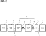
- a power transmission path A (the section enclosed by single-dot lines in Fig. 1 ) between the engine 1 and the second motor generator 3 shall next be described.
- Figure 2 is a schematic representation of the power transmission path A.
- the flywheel 1b, the damper 1c, and the gear box 4 are disposed in the power transmission path A between the engine 1 and the first motor generator 2.
- the damper 1c is for minimizing torque fluctuation transmitted from the engine 1 to the second motor generator 3.
- the damper 1c is configured from an inner hub 30 connected to the engine shaft 41 of the gear box 4, an outer hub 32 connected to the inner hub 30 via low-elasticity dampers 31, and high-elasticity dampers 33 connecting the outer hub 32 and the flywheel 1b.
- the low-elasticity dampers 31 and the high-elasticity dampers 33 are all springs, and the low-elasticity dampers 31 have a lower spring constant than the high-elasticity dampers 33.
- the inner hub 30 is equivalent to a first hub or first member of the present invention
- the outer hub is equivalent to a second hub or second member of the present invention
- the low-elasticity dampers 31 are equivalent to a damper of the present invention.
- Figure 3 is a front view of the damper 1c.
- the inner hub 30 has a hole 30a in a center through which the engine shaft 41 is inserted, and has a cutaway part in an outer periphery.
- the outer hub 32 has a cutaway part in an inner periphery, in a position facing the cutaway part of the inner hub.
- the low-elasticity dampers 31 are extensibly disposed at a position defined by the cutaway part of the inner hub 30 and the cutaway part of the outer hub 32. There are four low-elasticity dampers 31 in the present embodiment, but this number is not provided by way of limitation; for example, there may be two or three.
- the outer hub 32 also has a cutaway part in the outer periphery.
- the flywheel 1b has a cutaway part in an inner periphery, in a position facing the cutaway part in the outer periphery of the outer hub 32.
- the high-elasticity dampers 33 are extensibly disposed at a position defined by the cutaway part in the outer periphery of the outer hub 32 and the cutaway part of the flywheel 1b. There are four high-elasticity dampers 33 in the present embodiment, but this number is not provided by way of limitation; for example, there may be two or three.
- Figures 4 and 5 are enlarged views of the section closed by the dashed line B in Fig. 3 .
- Figure 4 shows a state in which there is no torsion in the inner hub 30 and the outer hub 32
- Fig. 5 shows a state in which the inner hub 30 and the outer hub 32 are in contact with each other.
- a protrusion 30a is provided on the outer periphery of the inner hub 30, and a protrusion 32a is provided on the inner periphery of the outer hub 32.
- a protrusion 30a is provided on the outer periphery of the inner hub 30, and a protrusion 32a is provided on the inner periphery of the outer hub 32.
- the protrusion 30a and the protrusion 32a rotate relative to each other, and the low-elasticity dampers 31 contract. Torque fluctuation can be absorbed by the low-elasticity dampers 31 until the protrusion 30a and the protrusion 32a come into contact with each other as shown in Fig. 5 .
- a relationship between the outer hub 32, the flywheel 1b, and the high-elasticity dampers 33 is the same as a relationship between the inner hub 30, the outer hub 32, and the low-elasticity dampers 31 described above.
- the high-elasticity dampers 33 expand and contract to absorb the torque fluctuation.
- a relationship between torsion angle and torque inputted to the damper 1c is as shown in, for example, Fig. 6 due to the action of the low-elasticity dampers 31 and the high-elasticity dampers 33.
- a torsion angle area in which the torque fluctuation can be absorbed by the low-elasticity dampers 31 is a low torsion angle area
- a torsion angle area in which the torque fluctuation can be absorbed by the high-elasticity dampers 33 is a high torsion angle area.
- input torque being positive or negative
- input torque from the engine 1 is positive and input torque from the second motor generator 3 is negative.
- the low torsion angle area is equivalent to a "range in which torque fluctuation caused by torsion in the first hub and the second hub can be absorbed by the damper" in the present invention.
- Points I/P1 and I/P2 in Fig. 6 shall be described hereinafter.
- first ignition means an initial ignition in the cylinders in the case of a multicylinder engine.
- the engine 1 which does not generate torque during cranking, will abruptly generate torque due to the initial explosion.
- the initial explosion is performed while the torque is in the low torsion angle area and the torque then transitions to the high torsion angle, the inner hub 30 and the outer hub 32 collide and "gear rattle" occurs. If such a collision is repeated every time the engine starts, the inner hub 30 and the outer hub 32 become progressively worn.
- the collision mentioned here is a collision between the protrusion 30a of the inner hub 30 and the protrusion 32a of the outer hub 32 as shown in Fig. 5 .
- Performing a first ignition after reaching a high torsion angle area through cranking is known as a method for minimizing the occurrence of the above-described gear rattle and wear of the inner hub 30 and outer hub 32.
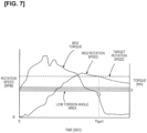
- An example of this method is shown in Fig. 7 as a reference example.
- the torque of the second motor generator 3 (referred to below also as MG2 torque) increases, and the rotation speed of the second motor generator 3 (referred to below also as MG2 rotation speed) thereby increases.
- the MG2 rotation speed in this embodiment is converted to rotation speed of the engine shaft 41 on the basis of a reduction ratio of the gear box 4. Therefore, the MG2 rotation speed can be regarded to be the same as the rotation speed of the engine 1.
- the torque area containing diagonal lines in Fig. 7 is a low torsion angle area, and other areas are high torsion angle areas.
- the target rotation speed for the first ignition in this embodiment is the rotation speed of the second motor generator 3 equivalent to a target engine rotation speed for starting the engine, i.e., the engine rotation speed at which the engine 1 can be started.
- the MG2 rotation speed then begins to decrease, and the first ignition is performed at a timing Tign1 at which the MG2 torque transitions from the low torsion angle area to the high torsion angle area.
- the torsion angle and the input torque at the timing Tign1 is I/P1 in Fig. 6 .
- the state of the inner hub 30 pushing the outer hub 32 up until then is changed to a state of the outer hub 32 pushing the inner hub 30 during the lowering of the rotation speed.
- the second motor generator 3 is driven by the torque of the engine 1, and the outer hub 32 therefore pushes the inner hub 30.
- the outer hub 32 comes to push the inner hub 30 when the first ignition is performed, and the inner hub 30 and the outer hub 32 therefore do not collide even if the engine torque caused by the initial explosion is inputted. Because there is no collision, there is no gear rattle, and wear can also be suppressed.
- the engine starting method of the reference example even if the MG2 rotation speed has reached the target rotation speed, i.e., the engine 1 could be started if an ignition is performed, it is necessary to wait until the high torsion angle area is reached. Therefore, there is room for improvement in the engine starting method of the reference example from the viewpoint of shortening the engine starting time.
- the electric power that can be supplied by the battery 5 in a series hybrid vehicle is less than the power needed for the maximum acceleration of the vehicle, the engine 1 must be started and electric power must be supplied from the battery 5 and the second motor generator 3 to the first motor generator 2 during maximum acceleration; therefore, prompt engine starting is desired.
- Maximum acceleration refers to acceleration under high load conditions, such as merging into a main lane on a highway or acceleration for overtaking during high-speed travel.
- the engine start control described below is executed in order to shorten the engine start time while minimizing gear rattle and wear due to the collision between the inner hub 30 and the outer hub 32.
- the vehicle to which the present embodiment is applied is a series hybrid vehicle in which the electric power that can be supplied by the battery 5 is less than the electric power required at the time of maximum acceleration of the vehicle.
- the first ignition when the MG2 rotation speed reaches the target rotation speed for the first ignition, or in other words, when the engine rotation speed reaches the target rotation speed for starting the engine, the first ignition is performed.
- the torsion angle and input torque at this time are at the point I/P2 in Fig. 6 .
- the time required to start the engine can thereby be shortened as compared with the reference example.
- the engine torque generated by the first ignition is suppressed below the engine torque generated by the second and subsequent ignitions.
- second and subsequent ignitions means the second and subsequent ignitions in the cylinders in the case of a multi-cylinder engine.
- FIG 8 is a flowchart of the control routine for engine start control executed by the controller 100.
- the present control routine is programmed into the controller 100.
- step S100 the controller 100 determines whether or not there is an engine start request, executes the process of step S110 when there is an engine start request, and repeats the process of the present step when there is not. There is determined to be an engine start request in cases such as when the SOC of the battery 5 has decreased to the set SOC, or when the vehicle accelerates, requiring more electric power than what can be supplied by the battery 5.
- step S110 the controller 100 instructs the second motor generator 3 to begin cranking.
- step S120 the controller 100 controls the rotation speed of the second motor generator 3. Specifically, a profile of the engine rotation speed up to the target engine rotation speed for starting the engine is set, and the rotation speed of the second motor generator 3 is controlled according to the rotation speed profile of the second motor generator 3 for realizing the engine rotation speed profile.
- the target engine rotation speed for starting the engine and the profile up to the target engine rotation speed are set in accordance with the specifications of the engine to which this control is applied.
- step S130 the controller 100 determines whether or not the engine rotation speed has exceeded a first threshold value.
- the process of step S140 is executed, and when the result is negative, the process returns to step S120.
- the process of step S130 is to issue a target torque reduction command (described hereinafter) before the engine rotation speed reaches the target engine rotation speed. Therefore, the first threshold value is, for example, a rotation speed that is about several hundred rotations lower than the target engine rotation speed for starting the engine.
- step S140 the controller 100 issues a target torque reduction command.
- the target torque reduction command is a command to reduce the target torque for the first ignition, and the second and subsequent ignitions use the target torque of normal control.
- the target engine torque in the first ignition is reduced below the target engine torque in the second and subsequent ignitions, and the engine torque actually generated is also reduced by being controlled according to the target engine torque after the reduction.
- the reduction amount is set according to the specifications of the engine to which this control is applied.
- the engine torque that can satisfy the durability performance is specified in advance by experiments, etc., in accordance with the wear characteristics of the inner hub 30 and the outer hub 32, and the reduction amount is set on the basis of this engine torque.
- step S150 the controller 100 determines whether or not the state in which the engine rotation speed is near the target engine rotation speed has continued for a preset time t1.
- Step 150 is for appropriately determining whether or not the engine rotation speed has reached the target engine rotation speed.
- the value for the determination is not "the target engine rotation speed” but “the state of being near the target engine rotation speed” because the fact that the engine rotation speed also fluctuates slightly due to the torque fluctuation of the engine 1 is also taken into consideration.
- the state of being near the target engine rotation speed is a state in which the engine rotation speed is within a range of about several tens [rpm] centered on the target engine rotation speed.
- the time t1 is set as the continuation time in order to avoid erroneous assessments due to noise, etc.
- step S160 the controller 100 performs the first ignition.
- step S170 the controller 100 determines whether or not the initial explosion is complete, ends the present routine if so, and returns to the process of step S160 if not.
- the initial explosion is determined to be complete when, for example, the state of the torque of the second motor generator 3 being less than a torque threshold value continues for a time t2.
- the torque threshold value in this case is, for example, a value that causes the engine torque resulting from the first ignition to be a negative value.
- the engine 1 begins to operate autonomously, and it is determined whether or not the engine torque is transmitted to the second motor generator 3.
- the time t2 is set as the continuation time in order to avoid erroneous assessments due to noise, etc.
- the actually generated engine torque is reduced by reducing the target engine torque in step S140, but another method may be used as long as the actually generated engine torque can be reduced. For example, a command to retard the ignition timing without changing the target engine torque may be issued. In the case of a multi-cylinder engine, depending on the specifications of the vehicle, it may not be possible to identify the cylinder to be ignited first and to retard only a specific cylinder at the time of starting. In this case, the first ignition timing of each cylinder is retarded, and the ignition timing under normal control is resumed in and after the next cycle.
- the elastic modulus of the low-elasticity dampers 31 is set so that the torsion angle is in the low torsion angle area when the engine rotation speed is near the target engine rotation speed due to cranking.
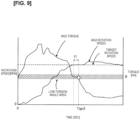
- FIG. 9 is a timing chart of when the engine start control according to the present embodiment is executed.
- the MG2 rotation speed can be regarded to be the same as the engine rotation speed.
- the first ignition is performed at a timing Tign2 at which the time t1 elapses after the MG2 rotation speed comes to be near the target rotation speed.
- the MG2 torque is of such magnitude that the torsion angle is within the low torsion angle area.
- the MG2 torque decreases due to input of the torque resulting from the initial explosion of the engine 1, but the engine torque resulting from the first ignition is suppressed, the minimization is stopped in the second and subsequent ignitions, and torque is therefore reduced in two stages as shown in Fig. 9 .
- the reduction amount of the first stage is less than the reduction amount after the first ignition in the reference example of Fig. 7 .
- a method for starting an engine of a vehicle comprising an inner hub 30 (first hub), an outer hub (second hub), and low-elasticity dampers 31 (damper) connecting the inner hub 30 and the outer hub 32 in a power transmission path A between a second motor generator 3 (generator) and an engine 1.
- This engine starting method assesses whether or not the engine 1 needs to be started, and begins to crank the engine 1 via the second motor generator 3 when the engine 1 needs to be started.
- a first ignition is then performed when torque fluctuation caused by torsion in the inner hub 30 and the outer hub 32 is in a range of being absorbable by the damper during cranking, i.e., when the torsion angle is in a low torsion angle area, and the engine torque generated by the first ignition is suppressed below the engine torque generated by the second and subsequent ignitions.
- the engine torque causes the inner hub 30 and the outer hub 32 to collide, but in the present embodiment, gear rattle and wear can be reduced because the engine torque generated by the first ignition is suppressed below the engine torque generated by the second and subsequent ignitions.
- the initial explosion in the engine 1 is caused before a transition from the low torsion angle area to the high torsion angle area, and the time required for the engine to start can therefore be reduced as compared with performing the first ignition after the transition to the high torsion angle area.
- the engine torque generated by the first ignition is suppressed by setting the target engine torque during the first ignition to be less than the target engine torque during the second and subsequent ignitions. This feature makes it possible to suppress the engine torque resulting from the first ignition.
- the engine torque generated by the first ignition may be suppressed by having the ignition timing during the first ignition be later than the ignition timing during the second and subsequent ignitions. This feature also makes it possible to suppress the engine torque resulting from the first ignition.
- the engine starting method of the present embodiment can be applied to a series hybrid vehicle in which electric power that can be supplied by a battery is less than electric power required for maximum acceleration of the vehicle.
- the engine 1 In such a series hybrid vehicle, the engine 1 must be started to perform power generation when maximum acceleration force is needed, as in the case of, for example, acceleration on a high-speed road. Therefore, acceleration performance of the vehicle improves when the time required to start the engine is shortened by the engine starting method of the present embodiment.
- the first ignition may be performed when the engaging parts of the two members are in a range of not being in contact with each other during cranking, and the engine torque generated by the first ignition may be suppressed below the engine torque generated by the second and subsequent ignitions.
- a coupling point e.g., a spline fitting, etc.
Landscapes
- Engineering & Computer Science (AREA)
- General Engineering & Computer Science (AREA)
- Combustion & Propulsion (AREA)
- Chemical & Material Sciences (AREA)
- Mechanical Engineering (AREA)
- Signal Processing (AREA)
- Transportation (AREA)
- Aviation & Aerospace Engineering (AREA)
- Acoustics & Sound (AREA)
- Physics & Mathematics (AREA)
- Theoretical Computer Science (AREA)
- Hybrid Electric Vehicles (AREA)
- Control Of Vehicle Engines Or Engines For Specific Uses (AREA)
- Electric Propulsion And Braking For Vehicles (AREA)
Claims (5)
- Verfahren zum Starten eines Motors eines Fahrzeugs, das einen Motor (1), einen Generator (3), eine erste Nabe (30), eine zweite Nabe (32) und einen Dämpfer (31) aufweist, der die erste Nabe und die zweite Nabe in einem Kraftübertragungsweg zwischen dem Motor und dem Generator verbindet, wobei der Generator konfiguriert ist, elektrische Energie zu erzeugen und das Fahrzeug anzutreiben; wobei das Verfahren zum Anlassen des Motors aufweist:Bestimmen, ob der Motor gestartet werden muss oder nicht;Anlassen des Motors durch den Generator, wenn festgestellt wird, dass der Motor gestartet werden muss;Durchführen einer ersten Zündung des Motors, wenn festgestellt wird, dass der Motor eine Zieldrehzahl erreicht hat; undSteuern der ersten Zündung derart, dass ein durch die erste Zündung erzeugtes Motordrehmoment unter einem Soll-Motordrehmoment liegt, das bei einer zweiten Zündung und nachfolgenden Zündungen verwendet werden soll, wobei die Solldrehzahl eine Drehzahl ist, bei der ein Torsionswinkel zwischen der ersten Nabe und der zweiten Nabe in einem Bereich mit niedrigem Torsionswinkel liegt, wobei der Bereich mit niedrigem Torsionswinkel ein Bereich ist, in dem die erste Nabe und die zweite Nabe nicht miteinander kollidiert sind und eine Drehmomentschwankung, die durch eine zwischen der ersten Nabe und der zweiten Nabe auftretende Torsion verursacht wird, durch den Dämpfer während des Anlassens absorbiert werden kann.
- Verfahren zum Starten eines Motors eines Fahrzeugs nach Anspruch 1, wobei das Steuern der ersten Zündung das Einstellen eines Soll-Motordrehmoments für die Durchführung der ersten Zündung derart umfasst, dass es geringer ist als das Soll-Motordrehmoment, das für die zweite Zündung und nachfolgende Zündungen verwendet werden soll, so dass das von der ersten Zündung erzeugte Motordrehmoment kleiner ist als ein von der zweiten Zündung und nachfolgenden Zündungen erzeugtes Motordrehmoment.
- Verfahren zum Starten eines Motors eines Fahrzeugs nach Anspruch 1, wobei das Steuern der ersten Zündung das Einstellen eines Zündzeitpunkts während der ersten Zündung derart umfasst, dass er später als ein Zündzeitpunkt während der zweiten Zündung und der nachfolgenden Zündungen ist.
- Serienhybridfahrzeug, auf das das Verfahren zum Starten eines Motors eines Fahrzeugs nach einem der Ansprüche 1 bis 3 angewendet wird, wobei die elektrische Leistung, die von einer Batterie (5) geliefert werden kann, geringer ist als die elektrische Leistung, die für eine maximale Beschleunigung des Fahrzeugs erforderlich ist.
- Vorrichtung zum Starten eines Motors eines Fahrzeugs, das aufweist:einen Generator (3), der konfiguriert ist, Strom zu erzeugen und das Fahrzeug anzutreiben;einen Motor (1), der über einen Kraftübertragungsweg mit dem Generator verbunden ist;eine erste Nabe (30) und eine zweite Nabe (32), die im Kraftübertragungsweg angeordnet sind;einen Dämpfer (31), der die erste Nabe und die zweite Nabe verbindet; undeine Steuereinheit (100), die den Generator und den Motor steuert, wobei die Steuereinheit programmiert ist, umfestzustellen, ob der Motor gestartet werden muss oder nicht,den Motor durch den Generator anzulassen, wenn festgestellt wird, dass der Motor gestartet werden muss,eine erste Zündung durchzuführen, wenn festgestellt wird, dass der Motor eine Solldrehzahl erreicht hat, wobei die Solldrehzahl eine Drehzahl ist, bei der ein Torsionswinkel zwischen der ersten Nabe und der zweiten Nabe in einem Bereich mit geringem Torsionswinkel liegt, wobei der Bereich mit geringem Torsionswinkel ein Bereich ist, in dem die erste Nabe und die zweite Nabe nicht miteinander kollidiert sind und eine Drehmomentschwankung, die durch eine zwischen der ersten Nabe und der zweiten Nabe auftretende Torsion verursacht wird, durch den Dämpfer während des Anlassen absorbiert werden kann, undwobei die erste Zündung so gesteuert wird, dass ein durch die erste Zündung erzeugtes Motordrehmoment unter einem Soll-Motordrehmoment liegt, das bei einer zweiten Zündung und nachfolgenden Zündungen verwendet werden soll.
Applications Claiming Priority (1)
| Application Number | Priority Date | Filing Date | Title |
|---|---|---|---|
| PCT/JP2019/043957 WO2021090491A1 (ja) | 2019-11-08 | 2019-11-08 | 車両のエンジン始動方法、シリーズハイブリッド車両及び車両のエンジン始動装置 |
Publications (3)
| Publication Number | Publication Date |
|---|---|
| EP4056830A1 EP4056830A1 (de) | 2022-09-14 |
| EP4056830A4 EP4056830A4 (de) | 2022-11-30 |
| EP4056830B1 true EP4056830B1 (de) | 2024-08-21 |
Family
ID=75848302
Family Applications (1)
| Application Number | Title | Priority Date | Filing Date |
|---|---|---|---|
| EP19951238.5A Active EP4056830B1 (de) | 2019-11-08 | 2019-11-08 | Startverfahren für fahrzeugmotor, serielles hybridfahrzeug und startvorrichtung für fahrzeugmotor |
Country Status (5)
| Country | Link |
|---|---|
| US (1) | US11719211B2 (de) |
| EP (1) | EP4056830B1 (de) |
| JP (1) | JP7452550B2 (de) |
| CN (1) | CN114599868B (de) |
| WO (1) | WO2021090491A1 (de) |
Families Citing this family (3)
| Publication number | Priority date | Publication date | Assignee | Title |
|---|---|---|---|---|
| US11719211B2 (en) * | 2019-11-08 | 2023-08-08 | Nissan Motor Co., Ltd. | Vehicle engine starting method, series hybrid vehicle, and vehicle engine starting device |
| JP7708026B2 (ja) * | 2022-07-29 | 2025-07-15 | トヨタ自動車株式会社 | ハイブリッド車両の制御装置 |
| JP7722305B2 (ja) * | 2022-09-16 | 2025-08-13 | トヨタ自動車株式会社 | 車両用制御装置 |
Family Cites Families (26)
| Publication number | Priority date | Publication date | Assignee | Title |
|---|---|---|---|---|
| JP3044880B2 (ja) * | 1991-11-22 | 2000-05-22 | トヨタ自動車株式会社 | シリーズハイブリッド車の駆動制御装置 |
| JP4013259B2 (ja) * | 2004-07-12 | 2007-11-28 | アイシン・エィ・ダブリュ株式会社 | ハイブリッド型車両用動力伝達装置 |
| JP4175361B2 (ja) | 2005-11-07 | 2008-11-05 | トヨタ自動車株式会社 | ハイブリッド車及びその制御方法 |
| JP4193839B2 (ja) * | 2005-12-19 | 2008-12-10 | トヨタ自動車株式会社 | 動力出力装置及びそれを搭載した車両 |
| JP2009184367A (ja) * | 2008-02-01 | 2009-08-20 | Toyota Motor Corp | 動力出力装置およびこれを備える車両ならびに動力出力装置の制御方法 |
| CN102057155B (zh) * | 2008-06-10 | 2013-07-10 | 日产自动车株式会社 | 内燃机控制器 |
| CN103201151A (zh) * | 2010-11-08 | 2013-07-10 | 丰田自动车株式会社 | 混合动力汽车 |
| US8858345B2 (en) * | 2010-11-19 | 2014-10-14 | Toyota Jidosha Kabushiki Kaisha | Vehicle damper device |
| WO2012073323A1 (ja) * | 2010-11-30 | 2012-06-07 | トヨタ自動車株式会社 | ハイブリッド車両の制御装置 |
| JP5776673B2 (ja) * | 2012-12-07 | 2015-09-09 | トヨタ自動車株式会社 | ハイブリッド車両の制御装置 |
| JP5447746B1 (ja) * | 2013-01-21 | 2014-03-19 | トヨタ自動車株式会社 | 車両の制御装置 |
| RU2636844C2 (ru) * | 2013-09-13 | 2017-11-28 | Ниссан Мотор Ко., Лтд. | Демпфирующее устройство |
| JP6020522B2 (ja) * | 2014-07-22 | 2016-11-02 | トヨタ自動車株式会社 | ハイブリッド車 |
| JP2016118272A (ja) * | 2014-12-22 | 2016-06-30 | アイシン精機株式会社 | ダンパ装置及び駆動システム |
| JP6696342B2 (ja) | 2016-07-29 | 2020-05-20 | 日産自動車株式会社 | エンジン始動方法及びエンジン始動装置 |
| JP6485651B2 (ja) * | 2016-08-31 | 2019-03-20 | トヨタ自動車株式会社 | 内燃機関の制御装置 |
| JP6536543B2 (ja) * | 2016-11-17 | 2019-07-03 | トヨタ自動車株式会社 | 車両用制御装置 |
| JP6828440B2 (ja) * | 2017-01-10 | 2021-02-10 | アイシン精機株式会社 | ダンパ装置 |
| JP6443464B2 (ja) * | 2017-01-27 | 2018-12-26 | トヨタ自動車株式会社 | 車両の制御装置 |
| JP6822908B2 (ja) * | 2017-06-27 | 2021-01-27 | 株式会社Soken | 車両の制御装置 |
| JP2019049303A (ja) * | 2017-09-08 | 2019-03-28 | アイシン精機株式会社 | ダンパ |
| US10166988B1 (en) * | 2017-12-04 | 2019-01-01 | GM Global Technology Operations LLC | Method and apparatus for controlling an internal combustion engine |
| JP6900908B2 (ja) * | 2018-01-09 | 2021-07-07 | トヨタ自動車株式会社 | 車両用制御装置 |
| JP7027920B2 (ja) * | 2018-02-01 | 2022-03-02 | トヨタ自動車株式会社 | ハイブリッド車両の制御装置 |
| JP7028040B2 (ja) * | 2018-04-16 | 2022-03-02 | トヨタ自動車株式会社 | 車両用制御装置 |
| US11719211B2 (en) * | 2019-11-08 | 2023-08-08 | Nissan Motor Co., Ltd. | Vehicle engine starting method, series hybrid vehicle, and vehicle engine starting device |
-
2019
- 2019-11-08 US US17/770,308 patent/US11719211B2/en active Active
- 2019-11-08 WO PCT/JP2019/043957 patent/WO2021090491A1/ja not_active Ceased
- 2019-11-08 CN CN201980101770.6A patent/CN114599868B/zh active Active
- 2019-11-08 EP EP19951238.5A patent/EP4056830B1/de active Active
- 2019-11-08 JP JP2021554546A patent/JP7452550B2/ja active Active
Also Published As
| Publication number | Publication date |
|---|---|
| US20220389896A1 (en) | 2022-12-08 |
| CN114599868A (zh) | 2022-06-07 |
| EP4056830A1 (de) | 2022-09-14 |
| JP7452550B2 (ja) | 2024-03-19 |
| EP4056830A4 (de) | 2022-11-30 |
| US11719211B2 (en) | 2023-08-08 |
| JPWO2021090491A1 (de) | 2021-05-14 |
| CN114599868B (zh) | 2023-11-28 |
| WO2021090491A1 (ja) | 2021-05-14 |
Similar Documents
| Publication | Publication Date | Title |
|---|---|---|
| RU2722810C1 (ru) | Способ управления и устройство управления силовой установкой гибридного транспортного средства | |
| US6976934B2 (en) | Shift control system for hybrid vehicles | |
| CN108556836B (zh) | 功率分流混合动力汽车制动器辅助起动发动机的控制方法 | |
| US8983703B2 (en) | Device for controlling hybrid vehicle | |
| US8578904B2 (en) | Device and method for starting engine | |
| US9840250B2 (en) | Vehicle drive apparatus | |
| EP4056830B1 (de) | Startverfahren für fahrzeugmotor, serielles hybridfahrzeug und startvorrichtung für fahrzeugmotor | |
| US20160251010A1 (en) | Control system for a vehicle | |
| JP6950601B2 (ja) | ハイブリッド車両の制御装置 | |
| EP3030464B1 (de) | Steuersystem für hybridfahrzeug | |
| JP2013123939A (ja) | 車両駆動システムの制御装置 | |
| WO2013042217A1 (ja) | 車両および車両用制御方法 | |
| CN110997379B (zh) | 车辆的控制装置及控制方法 | |
| JP2021059265A (ja) | ハイブリッド車両の充電制御方法及びハイブリッド車両の充電制御装置 | |
| JP2004322761A (ja) | 車両の駆動装置 | |
| US20230083915A1 (en) | Method and Device for Controlling Hybrid Vehicle | |
| JP3983162B2 (ja) | 車両用内燃機関の制御装置 | |
| US10640118B2 (en) | Method for controlling powertrain of vehicle | |
| KR102417546B1 (ko) | 하이브리드 차량의 엔진 진동 저감을 위한 제어 방법 | |
| JP7615648B2 (ja) | 駆動装置及び駆動装置を備えた車両 | |
| JP4124163B2 (ja) | ハイブリッド車の制御装置 | |
| JP2010155513A (ja) | ハイブリッド自動車 | |
| JP7647167B2 (ja) | ハイブリッド車両の制御装置 | |
| JP2006347239A (ja) | ハイブリッド車両のバッテリ保護制御装置 | |
| CN109591795B (zh) | 混合动力车辆的控制装置以及方法 |
Legal Events
| Date | Code | Title | Description |
|---|---|---|---|
| STAA | Information on the status of an ep patent application or granted ep patent |
Free format text: STATUS: THE INTERNATIONAL PUBLICATION HAS BEEN MADE |
|
| PUAI | Public reference made under article 153(3) epc to a published international application that has entered the european phase |
Free format text: ORIGINAL CODE: 0009012 |
|
| STAA | Information on the status of an ep patent application or granted ep patent |
Free format text: STATUS: REQUEST FOR EXAMINATION WAS MADE |
|
| 17P | Request for examination filed |
Effective date: 20220531 |
|
| AK | Designated contracting states |
Kind code of ref document: A1 Designated state(s): AL AT BE BG CH CY CZ DE DK EE ES FI FR GB GR HR HU IE IS IT LI LT LU LV MC MK MT NL NO PL PT RO RS SE SI SK SM TR |
|
| REG | Reference to a national code |
Ref country code: DE Free format text: PREVIOUS MAIN CLASS: F02D0029060000 Ref country code: DE Ref legal event code: R079 Ref document number: 602019057697 Country of ref document: DE Free format text: PREVIOUS MAIN CLASS: F02D0029060000 Ipc: F02P0005150000 |
|
| A4 | Supplementary search report drawn up and despatched |
Effective date: 20221027 |
|
| RIC1 | Information provided on ipc code assigned before grant |
Ipc: B60W 30/20 20060101ALN20221021BHEP Ipc: F16F 15/121 20060101ALN20221021BHEP Ipc: F02N 11/04 20060101ALI20221021BHEP Ipc: B60W 10/06 20060101ALI20221021BHEP Ipc: B60K 6/46 20071001ALI20221021BHEP Ipc: B60W 20/17 20160101ALI20221021BHEP Ipc: F02D 29/06 20060101ALI20221021BHEP Ipc: F02P 5/15 20060101AFI20221021BHEP |
|
| DAV | Request for validation of the european patent (deleted) | ||
| DAX | Request for extension of the european patent (deleted) | ||
| GRAP | Despatch of communication of intention to grant a patent |
Free format text: ORIGINAL CODE: EPIDOSNIGR1 |
|
| STAA | Information on the status of an ep patent application or granted ep patent |
Free format text: STATUS: GRANT OF PATENT IS INTENDED |
|
| RIC1 | Information provided on ipc code assigned before grant |
Ipc: B60W 30/20 20060101ALN20240516BHEP Ipc: F16F 15/121 20060101ALN20240516BHEP Ipc: F16F 15/123 20060101ALI20240516BHEP Ipc: B60K 6/442 20071001ALI20240516BHEP Ipc: F02N 11/04 20060101ALI20240516BHEP Ipc: B60W 10/06 20060101ALI20240516BHEP Ipc: B60K 6/46 20071001ALI20240516BHEP Ipc: B60W 20/17 20160101ALI20240516BHEP Ipc: F02D 29/06 20060101ALI20240516BHEP Ipc: F02P 5/15 20060101AFI20240516BHEP |
|
| INTG | Intention to grant announced |
Effective date: 20240613 |
|
| GRAS | Grant fee paid |
Free format text: ORIGINAL CODE: EPIDOSNIGR3 |
|
| GRAA | (expected) grant |
Free format text: ORIGINAL CODE: 0009210 |
|
| STAA | Information on the status of an ep patent application or granted ep patent |
Free format text: STATUS: THE PATENT HAS BEEN GRANTED |
|
| AK | Designated contracting states |
Kind code of ref document: B1 Designated state(s): AL AT BE BG CH CY CZ DE DK EE ES FI FR GB GR HR HU IE IS IT LI LT LU LV MC MK MT NL NO PL PT RO RS SE SI SK SM TR |
|
| REG | Reference to a national code |
Ref country code: GB Ref legal event code: FG4D |
|
| REG | Reference to a national code |
Ref country code: CH Ref legal event code: EP |
|
| REG | Reference to a national code |
Ref country code: DE Ref legal event code: R096 Ref document number: 602019057697 Country of ref document: DE |
|
| REG | Reference to a national code |
Ref country code: IE Ref legal event code: FG4D |
|
| REG | Reference to a national code |
Ref country code: LT Ref legal event code: MG9D |
|
| REG | Reference to a national code |
Ref country code: NL Ref legal event code: MP Effective date: 20240821 |
|
| PG25 | Lapsed in a contracting state [announced via postgrant information from national office to epo] |
Ref country code: NO Free format text: LAPSE BECAUSE OF FAILURE TO SUBMIT A TRANSLATION OF THE DESCRIPTION OR TO PAY THE FEE WITHIN THE PRESCRIBED TIME-LIMIT Effective date: 20241121 |
|
| REG | Reference to a national code |
Ref country code: AT Ref legal event code: MK05 Ref document number: 1715684 Country of ref document: AT Kind code of ref document: T Effective date: 20240821 |
|
| PG25 | Lapsed in a contracting state [announced via postgrant information from national office to epo] |
Ref country code: NL Free format text: LAPSE BECAUSE OF FAILURE TO SUBMIT A TRANSLATION OF THE DESCRIPTION OR TO PAY THE FEE WITHIN THE PRESCRIBED TIME-LIMIT Effective date: 20240821 Ref country code: PL Free format text: LAPSE BECAUSE OF FAILURE TO SUBMIT A TRANSLATION OF THE DESCRIPTION OR TO PAY THE FEE WITHIN THE PRESCRIBED TIME-LIMIT Effective date: 20240821 Ref country code: PT Free format text: LAPSE BECAUSE OF FAILURE TO SUBMIT A TRANSLATION OF THE DESCRIPTION OR TO PAY THE FEE WITHIN THE PRESCRIBED TIME-LIMIT Effective date: 20241223 Ref country code: GR Free format text: LAPSE BECAUSE OF FAILURE TO SUBMIT A TRANSLATION OF THE DESCRIPTION OR TO PAY THE FEE WITHIN THE PRESCRIBED TIME-LIMIT Effective date: 20241122 Ref country code: FI Free format text: LAPSE BECAUSE OF FAILURE TO SUBMIT A TRANSLATION OF THE DESCRIPTION OR TO PAY THE FEE WITHIN THE PRESCRIBED TIME-LIMIT Effective date: 20240821 |
|
| PG25 | Lapsed in a contracting state [announced via postgrant information from national office to epo] |
Ref country code: BG Free format text: LAPSE BECAUSE OF FAILURE TO SUBMIT A TRANSLATION OF THE DESCRIPTION OR TO PAY THE FEE WITHIN THE PRESCRIBED TIME-LIMIT Effective date: 20240821 |
|
| PG25 | Lapsed in a contracting state [announced via postgrant information from national office to epo] |
Ref country code: LV Free format text: LAPSE BECAUSE OF FAILURE TO SUBMIT A TRANSLATION OF THE DESCRIPTION OR TO PAY THE FEE WITHIN THE PRESCRIBED TIME-LIMIT Effective date: 20240821 |
|
| PG25 | Lapsed in a contracting state [announced via postgrant information from national office to epo] |
Ref country code: AT Free format text: LAPSE BECAUSE OF FAILURE TO SUBMIT A TRANSLATION OF THE DESCRIPTION OR TO PAY THE FEE WITHIN THE PRESCRIBED TIME-LIMIT Effective date: 20240821 Ref country code: IS Free format text: LAPSE BECAUSE OF FAILURE TO SUBMIT A TRANSLATION OF THE DESCRIPTION OR TO PAY THE FEE WITHIN THE PRESCRIBED TIME-LIMIT Effective date: 20241221 |
|
| PG25 | Lapsed in a contracting state [announced via postgrant information from national office to epo] |
Ref country code: HR Free format text: LAPSE BECAUSE OF FAILURE TO SUBMIT A TRANSLATION OF THE DESCRIPTION OR TO PAY THE FEE WITHIN THE PRESCRIBED TIME-LIMIT Effective date: 20240821 |
|
| PG25 | Lapsed in a contracting state [announced via postgrant information from national office to epo] |
Ref country code: ES Free format text: LAPSE BECAUSE OF FAILURE TO SUBMIT A TRANSLATION OF THE DESCRIPTION OR TO PAY THE FEE WITHIN THE PRESCRIBED TIME-LIMIT Effective date: 20240821 Ref country code: RS Free format text: LAPSE BECAUSE OF FAILURE TO SUBMIT A TRANSLATION OF THE DESCRIPTION OR TO PAY THE FEE WITHIN THE PRESCRIBED TIME-LIMIT Effective date: 20241121 |
|
| PG25 | Lapsed in a contracting state [announced via postgrant information from national office to epo] |
Ref country code: RS Free format text: LAPSE BECAUSE OF FAILURE TO SUBMIT A TRANSLATION OF THE DESCRIPTION OR TO PAY THE FEE WITHIN THE PRESCRIBED TIME-LIMIT Effective date: 20241121 Ref country code: PT Free format text: LAPSE BECAUSE OF FAILURE TO SUBMIT A TRANSLATION OF THE DESCRIPTION OR TO PAY THE FEE WITHIN THE PRESCRIBED TIME-LIMIT Effective date: 20241223 Ref country code: PL Free format text: LAPSE BECAUSE OF FAILURE TO SUBMIT A TRANSLATION OF THE DESCRIPTION OR TO PAY THE FEE WITHIN THE PRESCRIBED TIME-LIMIT Effective date: 20240821 Ref country code: NO Free format text: LAPSE BECAUSE OF FAILURE TO SUBMIT A TRANSLATION OF THE DESCRIPTION OR TO PAY THE FEE WITHIN THE PRESCRIBED TIME-LIMIT Effective date: 20241121 Ref country code: NL Free format text: LAPSE BECAUSE OF FAILURE TO SUBMIT A TRANSLATION OF THE DESCRIPTION OR TO PAY THE FEE WITHIN THE PRESCRIBED TIME-LIMIT Effective date: 20240821 Ref country code: LV Free format text: LAPSE BECAUSE OF FAILURE TO SUBMIT A TRANSLATION OF THE DESCRIPTION OR TO PAY THE FEE WITHIN THE PRESCRIBED TIME-LIMIT Effective date: 20240821 Ref country code: IS Free format text: LAPSE BECAUSE OF FAILURE TO SUBMIT A TRANSLATION OF THE DESCRIPTION OR TO PAY THE FEE WITHIN THE PRESCRIBED TIME-LIMIT Effective date: 20241221 Ref country code: HR Free format text: LAPSE BECAUSE OF FAILURE TO SUBMIT A TRANSLATION OF THE DESCRIPTION OR TO PAY THE FEE WITHIN THE PRESCRIBED TIME-LIMIT Effective date: 20240821 Ref country code: GR Free format text: LAPSE BECAUSE OF FAILURE TO SUBMIT A TRANSLATION OF THE DESCRIPTION OR TO PAY THE FEE WITHIN THE PRESCRIBED TIME-LIMIT Effective date: 20241122 Ref country code: FI Free format text: LAPSE BECAUSE OF FAILURE TO SUBMIT A TRANSLATION OF THE DESCRIPTION OR TO PAY THE FEE WITHIN THE PRESCRIBED TIME-LIMIT Effective date: 20240821 Ref country code: ES Free format text: LAPSE BECAUSE OF FAILURE TO SUBMIT A TRANSLATION OF THE DESCRIPTION OR TO PAY THE FEE WITHIN THE PRESCRIBED TIME-LIMIT Effective date: 20240821 Ref country code: BG Free format text: LAPSE BECAUSE OF FAILURE TO SUBMIT A TRANSLATION OF THE DESCRIPTION OR TO PAY THE FEE WITHIN THE PRESCRIBED TIME-LIMIT Effective date: 20240821 Ref country code: AT Free format text: LAPSE BECAUSE OF FAILURE TO SUBMIT A TRANSLATION OF THE DESCRIPTION OR TO PAY THE FEE WITHIN THE PRESCRIBED TIME-LIMIT Effective date: 20240821 |
|
| PG25 | Lapsed in a contracting state [announced via postgrant information from national office to epo] |
Ref country code: DK Free format text: LAPSE BECAUSE OF FAILURE TO SUBMIT A TRANSLATION OF THE DESCRIPTION OR TO PAY THE FEE WITHIN THE PRESCRIBED TIME-LIMIT Effective date: 20240821 Ref country code: SM Free format text: LAPSE BECAUSE OF FAILURE TO SUBMIT A TRANSLATION OF THE DESCRIPTION OR TO PAY THE FEE WITHIN THE PRESCRIBED TIME-LIMIT Effective date: 20240821 Ref country code: RO Free format text: LAPSE BECAUSE OF FAILURE TO SUBMIT A TRANSLATION OF THE DESCRIPTION OR TO PAY THE FEE WITHIN THE PRESCRIBED TIME-LIMIT Effective date: 20240821 |
|
| PG25 | Lapsed in a contracting state [announced via postgrant information from national office to epo] |
Ref country code: EE Free format text: LAPSE BECAUSE OF FAILURE TO SUBMIT A TRANSLATION OF THE DESCRIPTION OR TO PAY THE FEE WITHIN THE PRESCRIBED TIME-LIMIT Effective date: 20240821 |
|
| PG25 | Lapsed in a contracting state [announced via postgrant information from national office to epo] |
Ref country code: CZ Free format text: LAPSE BECAUSE OF FAILURE TO SUBMIT A TRANSLATION OF THE DESCRIPTION OR TO PAY THE FEE WITHIN THE PRESCRIBED TIME-LIMIT Effective date: 20240821 |
|
| PG25 | Lapsed in a contracting state [announced via postgrant information from national office to epo] |
Ref country code: SK Free format text: LAPSE BECAUSE OF FAILURE TO SUBMIT A TRANSLATION OF THE DESCRIPTION OR TO PAY THE FEE WITHIN THE PRESCRIBED TIME-LIMIT Effective date: 20240821 Ref country code: IT Free format text: LAPSE BECAUSE OF FAILURE TO SUBMIT A TRANSLATION OF THE DESCRIPTION OR TO PAY THE FEE WITHIN THE PRESCRIBED TIME-LIMIT Effective date: 20240821 |
|
| REG | Reference to a national code |
Ref country code: DE Ref legal event code: R097 Ref document number: 602019057697 Country of ref document: DE |
|
| PLBE | No opposition filed within time limit |
Free format text: ORIGINAL CODE: 0009261 |
|
| STAA | Information on the status of an ep patent application or granted ep patent |
Free format text: STATUS: NO OPPOSITION FILED WITHIN TIME LIMIT |
|
| REG | Reference to a national code |
Ref country code: CH Ref legal event code: PL |
|
| PG25 | Lapsed in a contracting state [announced via postgrant information from national office to epo] |
Ref country code: MC Free format text: LAPSE BECAUSE OF FAILURE TO SUBMIT A TRANSLATION OF THE DESCRIPTION OR TO PAY THE FEE WITHIN THE PRESCRIBED TIME-LIMIT Effective date: 20240821 |
|
| PG25 | Lapsed in a contracting state [announced via postgrant information from national office to epo] |
Ref country code: LU Free format text: LAPSE BECAUSE OF NON-PAYMENT OF DUE FEES Effective date: 20241108 |
|
| REG | Reference to a national code |
Ref country code: CH Ref legal event code: PL |
|
| PG25 | Lapsed in a contracting state [announced via postgrant information from national office to epo] |
Ref country code: CH Free format text: LAPSE BECAUSE OF NON-PAYMENT OF DUE FEES Effective date: 20241130 |
|
| 26N | No opposition filed |
Effective date: 20250522 |
|
| REG | Reference to a national code |
Ref country code: BE Ref legal event code: MM Effective date: 20241130 |
|
| PG25 | Lapsed in a contracting state [announced via postgrant information from national office to epo] |
Ref country code: SE Free format text: LAPSE BECAUSE OF FAILURE TO SUBMIT A TRANSLATION OF THE DESCRIPTION OR TO PAY THE FEE WITHIN THE PRESCRIBED TIME-LIMIT Effective date: 20240821 |
|
| PG25 | Lapsed in a contracting state [announced via postgrant information from national office to epo] |
Ref country code: BE Free format text: LAPSE BECAUSE OF NON-PAYMENT OF DUE FEES Effective date: 20241130 |
|
| PG25 | Lapsed in a contracting state [announced via postgrant information from national office to epo] |
Ref country code: IE Free format text: LAPSE BECAUSE OF NON-PAYMENT OF DUE FEES Effective date: 20241108 |
|
| PGFP | Annual fee paid to national office [announced via postgrant information from national office to epo] |
Ref country code: DE Payment date: 20251022 Year of fee payment: 7 |
|
| PGFP | Annual fee paid to national office [announced via postgrant information from national office to epo] |
Ref country code: GB Payment date: 20251022 Year of fee payment: 7 |
|
| PGFP | Annual fee paid to national office [announced via postgrant information from national office to epo] |
Ref country code: FR Payment date: 20251022 Year of fee payment: 7 |
|
| PG25 | Lapsed in a contracting state [announced via postgrant information from national office to epo] |
Ref country code: HU Free format text: LAPSE BECAUSE OF FAILURE TO SUBMIT A TRANSLATION OF THE DESCRIPTION OR TO PAY THE FEE WITHIN THE PRESCRIBED TIME-LIMIT; INVALID AB INITIO Effective date: 20191108 |